1
,_EA/_S
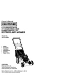
OWNER'S
MANUAL
Place Photo Here
MODEL NO.
917.297350
CRRFTXMRN
°
Caution:
Read and follow
all Safety Rules
and Instructions
Before Operating
This Equipment
5.0 HP
26 INCH TINE WIDTH
FRONT TINE TILLER
• Assembly
° Operation
° Customer Responsibilities
o Service and Adjustments
° Repair Parts
Safe Operation
SAFETY
RULES
for Walk-Behind
Practices
TRAINING
*
*
•
Read the Owner's Manual carefully. Be thoroughly
fam!Iiar with the controls and the proper use of the
equipment. Know how to stop the unit and disengage
the controls quickly°
Never allow children to operate the equipment. Never
allow adufts to operate the equipment without proper
instruction.
Keep the area of operation clear of all persons, particularly small children, and pets.
•
•
•
The roughly inspect the area where the equipment is to
be used and remove all foreign objects.
Disengage ail clutches and shift into neutral before
starting the engine (motor).
Do not operate the equipment without wearing adequate outer garrnents_ Wear footwear that will improve footing on slippery surfaces,
Handle fuel with care; it is highly flammable_
• Use an approved fuel container.
• NevJ add fuel to a running engine or hot engine.
° Fill fuel tank outdoors with extreme care. Never fill
fuel tank indoors.
•
•
•
Replace gasoline cap securely and clean up spilled
fuel before restarting.
Use extension cords and receptacles as specified by
the manufacturer for all units with electric drive motors
or eiectdc starting motors.
Never attempt to make any adjustments while the
engine (motor) is running (except where specifically
recommended by manufacturer).
Do not put hands or feet near or under rotating parts.
o
Exercise extreme caution when operating on or cressmg gravel drives, walks, or roads. Stay alert for hidden
hazards or traffic. Do not carry passengers.
After striking a foreign object, stop the engine (motor),
remove the wire from the spark plug, thoroughly inspect the tiller for any damage, and repair the damage
before restarting and operating the tiller°
Exercise caution to avoid slipping or falling.
°
•
•
Stop the engine (motor) when leaving the operating
position.
•
Take all possible precautions when Ieaving the machine unattended.
Disengage the tines, shift into
neutral, and stop the engine.
Before cleaning, repairing, or inspecting shut off the
eng ne and make certain all moving parts have stopped.
Disconnect the spark plug wire, and keep the wire
away from the plug to prevent accidental starting.
Disconnect the cord on electric motors.
•
•
•
•
•
•
°
•
•
Donot run the engine indoors; exhaust fumes are
dangerous.
Never operate the tiller' without proper guards, plates,
or other safety protective devices in place.
Keep children and pets away.
Do not overload the machine capacity by attempting to
till too deep at too fast a rate°
Never operate the machirTe at high speeds on slippery
surfaces. Look behind an# use care when backing_
Never allow bystanders near the unit.
Use only attachments and accessories approved by
the manufacturer of the tilIer (such as wheat weights,
counterweights, cabs, and the like).
Never operate the tiller without good visibility or light.
Be careful when tilling in hard ground_ The tines may
catch in the ground and propel the tiller forward, tf this
occurs, let go of the handlebars and do not restrain the
machine.
MAINTENANCE
AND STORAGE
•
Keep machine, attachments,
working condition.
•
Check shear pins, engine mounting bolts, and other
bolts at frequent intervals for proper tightness to be
sure the equipment is in safe working condition.
Never store the machine with fuel in the fuel tank inside
a building where ignition sources are present, such as
hot water and space heaters, clothes dryers, and the
like. A_low the engine to cool before storing in any
enctosure_
o
•
and accessories
in safe
Always refer to the operator's guide instructions for
important details if the tiller is to be stored for an
extended period.
- IMPORTANT CAUTIONS, tMPORTANTS, AND NOTES ARE A MEANS OF A'i-t'RACTING
INFORMATION IN "THIS MANUAL.
CAUTION: Look for this symbol to point
out important
safety precautions.
It
means--Attention!
Become Alert! Your
safety is involved.
Tillers
If the unit should start to vibrate abnormally, stop the
engine (motor) and check immediately for the cause.
Vibration is generally a warning of trouble.
OPERATION
•
Rotary
•
PREPARATION
•
Powered
IMPORTANT:
POSSIBILITY
ATTENTION TO IMPO RTANT OR CRITICAL
USED TO ALERT YOU THAT THERE
OF DAMAGING
THIS EQUIPMENT.
tS A
NOTE: Gives essential information that wi]l aid you to better
understand, incorporate, or execute a particular set of instructions.
CONGRATULATIONS
on your purchase of a Sears Tiller.
It has been designed, engineered and manufactured to
t_ive yoL the best possible dependability and performance.
PRODUCT
Should you experience any problems you cannot easily
remedy, piease contact your nearest authorized Sears
Service Center/Department.
They have competent, welltrained technicians and the proper tools to service or repair
this unit.
Please read and retain this manual. The instructions witl
enable you to assemble and maintain your tiller properly.
Always observe the "SAFETY RULES",
SPECIFICATIONS
HORSEPOWER:
5.0 HP
DISPLACEMENT:
12..57 cu. in.
GASOLINE
3 Quarts
CAPACITY:
Unleaded Regular
OIL (API-SG):
(CAPACITY:
MODEL
NUMBER
SAE 30W (Above 32°F)
20 oz.. [0..6L])
SPARK PLUG :
(GAP: _030" [076mini)
SAE 5W-30 (Betow 32°F)
Champion
RJ19LM (STD361458)
917,297350
SERIAL
NUMBER
MAINTENANCE
AGREEMENT
DATE OF
PURCHASE
A Sears Maintenance Agreement is available on this producto Contact your nearest Sears store for details.
THE MODEL AND SERIAL NUMBERS WILL BE
FOUND ON THE MODEL PLATE ATTACHED TO
THE RIGHT HAND ENGINE BRACKET°
CUSTOMER
*
Read and observe the safety rules,,
YOU SHOULD RECORD BOTH SERtAL NUMBER
AND DATE OF PURCHASE AND KEEP IN A SAFE
PLACE FOR FUTURE REFERENCE.
-
Fo!Iow a regular schedule in maintaining, cadng for and
using your tilter.
-
Follow
the
instructions
under
"Customer
Responsibilities" and "Storage" sections of this Owner's
Manual
RESPONSIBILITIES
IMPORTANT:
THIS UNIT 1S EQUIPPED
WITH AN INTERNAL COMBUSTION
ENGINE AND SHOULD NOT BE USED ON
OR NEAR ANY UNIMPROVED
FOREST-COVERED,
BRUSH-COVERED
OR GRASS COVERED
LAND UNLESS THE
ENGINE'S
EXHAUST SYSTEM IS EQUIPPED
WITH. A SPARK ARRESTER
MEETING APPLICABLE
LOCAL OR STATE
LAWS (IF ANY). IFA SPARKARRESTER
IS USED, IT SHOULD BE MAINTAINED
IN EFFECTIVE
WORKING
ORDER BY
THE OPERATOR.
IN THE STATE OF CALIFORNIA
THE ABOVE IS REQUIRED
BY LAW (SECTION
4442 OF THE CALIFORNIA
PUBLIC
RESOURCES
CODE).
OTHER STATES MAY HAVE SIMILAR LAWS.
FEDERAL LAWS APPLY ON FEDERAL
LANDS.
SEE YOUR SEARS AUTHORIZED
SERVICE CENTER/DEPARTMENT
FOR SPARK ARRESTER.
REFER TO THE REPAIR
PARTS SECTION OF THIS MANUAL FOR PART NUMBER.
LIMITED TWO YEAR WARRANTY
ON CRAFTSMAN
TILLER
For two (2) years from date of purchase, when this Craftsman Tiller is maintained, lubricated, and tuned up
according to the operating and maintenance instructions in the owner's manual, Sears will repair free of charge any
defect in material or workmanship.
This Warranty does not cover:.
°
Expendable items which become worn during normal use, such as tines, spark plugs, air cleaners and belts.
o
Repairs necessary because of operator abuse or negligence, including bent crankshafts
maintain the equipment according to the instructions contained in the owner's manual
•
If this Craftsman Tiller is used for commercial
from the date of purchase.
and the failure to
or rental purposes, this Warranty applies for only thirty (30) days
WARRANTY SERVICE IS AVAILABLE BY RETURNING THE CRAFTSMAN TILLER TO THE NEAREST SEARS
SERVICE CENTEPJDEPARTMENT IN THE UNITED STATES. THIS WARRANTY APPLIES ONLY WHILE THIS
PRODUCT 1S IN USE IN THE UNITED STATES.
This Warranty gives you specific legal rights, and you may also have other rights which vary from state to state.
SEARS, ROEBUCK AND COo, D/817 WA, HOFFMAN ESTATES, IL 60179
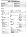
TABLE OF CONTENTS
,,,,=JH,=,,,,n
SAFETY
RULES
i
,,
,,,
,
...........................................................
ii,=l i=l
i
MAINTENANCE SCHEDULE ......................................
12
SERVICE & ADJUSTMENTS ................................. 14-17
STORAGE ....................................................................
18
TROUBLESHOOTING
.................................................
19
REPAIR PARTS-TILLER ........................................
20-25
REPAIR PARTS-ENGINE ....................................... 26-30
SERVICE/PARTS
ORDERING .................... Back Cover
2
CUSTOMER RESPONSIBILITIES ..................... 3, 12-14
PRODUCT SPECIFICATIONS ....................................... 3
WARRANTY ...................................................................
3
ACCESSORIES
.............................................................
5
ASSEMBLY ................................................................
6-7
OPERATION .............................................................
8-11
INDEX
A
Accessories
Oil Type ...................................t0,13
Repair Parts .......................... 26-30
Spark Plug ................................. 14
Starting ...................................... 10
Stopping ...................................... 9
Storage ....................................
18
Winter Operation ..................... 13
...........................................5
Adjustments:
Carburetor ............................... 17
Depth Stake ............................... 9
Handle Height .......................... 14
Tines ................................... 14-15
V-Belt ......................................... 16
Wheels ......................................... 9
Air Cleaner ...................................... 13
B
Belt, V-:
Belt Guard ........................ :...... 17
Repair Parts ............................. 21
V-Belt Replacement ........... _..... 16
C
Cooling System ..............................
Controls:
Choke ........................................
Throttle ......................................
Tines ..........................................
Cultivating ......................................
Customer Responsibilities:
Air Cleaner ...............................
Cooling System .......................
Finish .......................................
Maintenance Schedule ............
Muffler ......................................
Oil Change ................................
Spark Ptug ...............................
Transmission ...........................
13
8
8
8
11
13
13
14
12
14
13
14
t4
D
Depth Stake:
Adjustment ................................. 9
Repair Parts ............................. 22
E
Engine:
Air Cleaner ................................
Cooling System .......................
Fuel Type .................................
Lubrication ...............................
Oil Level ...................................
13
13
10
13
10
F
Fuel:
Filling Tank .................................
Storage .....................................
Type .............................................
Finish:
Maintenance .............................
10,
18
10"
14
H
Handle:
Height Adjustment .................... 14
Repair Parts ............................. 20
L
Lubrication:
Lubrication Chart .................... 12
Engine ...................................... 13
M
Muffler:
Maintenance ............................ 14
Spark Arrester ........................... 3
O
Oil:
Leve! ........................................
10
Type .................................... 10,13
Operation:
Cultivating ................................ 1 t
Fill Fuel _l ank ........................... 10
Starting Engine ........................ 10
Stopping Tines & Engine ........... 9
Tilling .........................................
9
Tilling Hints .............................. 11
line Operation ........................... g
Transporting Tiller .................... 10
Winter Operation ..................... 13
R
Repair Parts
Tiller ....................................... 20-24
Engine ................................ 26-30
Rules for Safe Operation ......................
2
S
Service & Adjustments:
Carburetor ................................ 17
Handle Height ........................... 14
Tines ...................................... 14-15
V-Belt ......................................... 16
Wheels ...................................................
9
Service:
Repair Parts ........................ 20-30
Service Record ......................... 12
Spark Plug:
Gap ............................................. 3
Maintenance ............................ 14
Storage:
Fuel System ............................. 18
Tiller .........................................
18
T
Tilling ............................................... 9,11
Tines:
Arrangement ........................ 14-15
Operation ................................... 9
Repair Parts .............................. 23
Replacement .............................. 15
Transmission:
Maintenance .............................. 14
Repair Parts .............................. 24
Troubleshooting ................................ 19
Transporting ................................... 10
W
Warranty ........................................... 3
Wheels:
Adjustments ............................... 9
Repair Parts ............................. 22
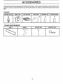
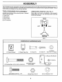
These accessories were available when the tiller was purchased. They are also available at most Sears Retail outlets
and Service Centers. Most Sears Stores can order repair parts for you when you provide the model number of your
tiller.
ENGINE
SPARK
PLUG
AIR FILTER
MUFFLER
ii
TILLER
i
GAS CAN
ENGINE
OIL
STABILIZER
,,,,,,,,,,,,,,,,,,,,, ,,,,,,,,,,,,,,
ii
MAINTENANCE
BELT
TINES
CLEVIS
0
t:.r->
5
PIN
HAIRPIN
CLIP
ASSEMBLY
i
i,i
i
ii,ll
,i,illl
i lllllll
, ill l i ii
i i
i,,,u,ill,,i,,
,lllllll
Your new tiller has been assembled at the factory with exception of those parts left unassembled for shipping purposes. To
ensure safe and proper operation of your tiller all parts and hardware you assemble must be tightened securely, Use the
correct tools as necessary to insure proper' tightness.
TOOLS
REQUIRED
FOR ASSEMBLY
OPERATOR'S
A socket wrench set will make assembly easier. Standard
wrench sizes are listed,
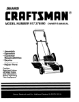
POSITION
(See Fig. 1)
When dght or left hand is mentioned in this manual, it
means when you are in the operating position (standing
behind tiller handles).
(1) Utility knife
(1) Screwdriver
FRONT
(1) Pair of pliers
(2) 1/2" wrenches
LEFT
IGHT
OPERATOR'S
POSITION
FIG. 1
CONTENTS
OF HARDWARE
PACK
©
(1) Owner's Manual
(1) Plastic Cable Clip
(1) Clevis Pin
Q
(2) Carriage Bolts 5/16-18 UNC x 2-3/8 Gr. 5
i,,i
Niiiiillllllllll
(1) Cotter Pin
©
©
©
(1) Washer
9/32 x 1/2 x 14 Gauge
(1) Reverse Rod Bracket
(_(1)
Bushing
(2) F{ange Locknuts
5/16-18 UNC
ii
Q
i!iti { jJil,imiitisi!t
nria
{li J!
(2) Hex Bolts 5/16-18 x 1,-t/4
(2) Hex Nuts 5/16-18
I,IHI
lll l
6
(2) Lock Washers
5/16
ASSEMBLY
UNPACKCARTON
staples when handling or disposing of
CAUTION: material.
Be careful of exposed
cartoning
! _
ii
,,H,IH
H
TINECONTROLCABLE
TINE CONTROL
HANDLE MOUNT
III
IMPORTANT:
WHEN UNPACKING AND ASSEMBLING
TILLER, BE CAREFUL NOT TO STRETCH OR KINK
CABLE(S).,
-
Cut cable ties securing handle column°
o
Slowly lift handle column and iay it over tiller°
COLUMN
.
" Remove packing from carton. Hardware pack is found
in folded cardboard packing.
=
S!]de handle cotumn onto handle mount,.
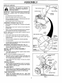
ASSEMBLE
HANDLE
(See Fig. 2)
=
Slide reverse rod through hote in reverse rod bracket
as shown.
•
Slide bushing over lower reverse rod and snap into
bracket hole.
•
Attach reverse rod bracket to handle column using two
(2) carriage bolts and two (2) flange tocknuts.
NOTE: Make sure tine control cable is routed in front of
reverse rod bracket.
CABLE
TINE CONTROL
•
Insert plastic cable clip into hole in handle column.
•
Route tine control cable through plastic cable clip on
handle column,
•
Remove packing material from handle assembly.
•
Cut away carton.
o
Cut cable ties securing tiller to skid. Remove tiller from
skid by pulling backwards.
ASSEMBLE
o
REVERSE
INSTALL DEPTH
(See
Fig. 3)
•
ROD (See
Fig. 2)
Secure upper reverse rod to lower reverse rod using
clevis pin, washer and cotter pin.
STAKE
ASSEMBLY
Insert stake support between engine bracket halves
with stake spring down,
CABLE
UPPER
REVERSE
ROD
CARRIAGE
BOLTS
CLEVIS
PIN
REVERSE
ROD
FLANGE
LOCKNUTS
LOWER
REVERSEROC
FIG. 2
NOTE: It may be necessary to loosen nut "A"°
•
Bolt stake support to engine brackets with bolts, {ock
washers and nuts. Tighten securely. Also tighten nut
"A" if it was necessary to loosen.
°
Depth stake must move freely, if it does not, loosen
support bolt.
HANDLE
•
DEPTH STAKE
IUPPORT
HEIGHT
Handle height may be adjusted to better suit operator.
(See HANDLE HEIGHT" in the Service and Adjustments section of this manual).
TILLING
•
ENGINE BRACKET
_LVES
WIDTH
DEPTH
STAKE
Tilling width may be adjusted to better handle your
tilting conditions (See "FINE ARRANGEMENT" in the
Service and Adjustments section of this manual).
TINE OPERATION
•
Check tine operation before first use. (See "TINE
OPERATION CHECK" in the Service and Adjustments
section of this manual).
SUPPORT
HEXBGLTS,
'LOCK WASHERS,
RG. 3
BOLT
AND HEX NUTS
OPERATION
,,,,,,
,,,Hi,
KNOW
i,,,,
i ,
,,,,,,,,,,,i ,,, J,
, ,i
...................
,,,,,,,,,,,,,,,,,,
,,,, ,,,,
YOUR TILLER
READ THIS OWNER'S
MANUAL AND SAFETY RULES BEFORE OPERATING
YOUR TILLER.
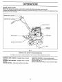
Compare the illustrations with your tiIler to familiarize yourself with the location of various controls and adjustments° Save
this manual for future reference.
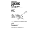
FORWARD
33NE CONTROL
CHOKE CONTROL
THROTTLE
DEPTH STAKE
RECOILSTARTERHANDLE
O
FIG. 4
MEETS
ANSI SAFETY
REQUIREMENTS
Our tillers conform to the safety standards of the American National Standards Institute.
FORWARD
direction.
REVERSE
direction.
TINE CONTROL
TINE CONTROL
CHOKE CONTROL
- Engages tines in forward
- Engages tines in reverse
- Used when starting a cold engine.
THROTTLE CONTROL- Controls engine speed.
DEPTH STAKE - Controls forward speed and the depth at
which the tiller will dig.
RECOIL STARTER HANDt.E - Used to start the engine.
OPERATIO
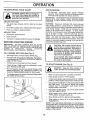
The operation of any tiller can result in foreign objects thrown into the eyes, which can
result in severe eye damage. Always wear safety glasses or eye shields before starting
your tiller and while tilling. We recommend a wide vision safety mask for over the spectacles or standard safety glasses.
TILLING
HOW TO USE YOUR TILLER
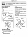
STOPPING
The speed and depth of tilling is regulated by the position
of the depth stake and wheel height.
(See Fig. 5)
TINES
•
Release forward tine control to stop forward movemenL
•
Release reverse tine control to stop reverse movement.
DEPTH STAKE (See Fig. 6)
ENGINE
-
Move throttle control to "STOP" position.
-
Never use choke to stop engine.
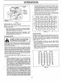
REVERSE
The depth stake should always be below the wheels for
digging. It serves as a brake to slow the tiller's forward
motion to enable the tines to penetrate the ground, Also,
the more the depth stake is lowered into the ground the
deeper the tines will dig°
TINE CONTROL
\-_
Adjust depth stake by removing the hairpin clip and clevis
pin. Change depth stake to desired position. Replace the
clevis pin and hairpin clip.
FORWARD TINE CONTROL
"OFF" (UP) POSITION
•
For normal tilling, set depth stake at the second or third
hole from the top.
WHEELS (See Fig. 6)
Adjust wheels by removing the hairpin clip and clevis pin.
Change wheel position. Replace the hairpin clip and clevis
pin.
•
For normal tilling, set wheels at the second or third hole
from the top_
__,L
HAIRPIN CLIP
AND CLEVIS PIN
,_
"ON"
(DOWN) POSITION
DEPT_{
STAKE
CHOKE
,THROTTLE
HAIRPIN CLIP
AND CLEVIS PiN
SPRING
_"WHEEL
FIG. 5
T1NE OPERATION
(See Fig. 5)
Start engine and move throttle control to desired speed.
FORWARD
•
Squeeze forward tine control to handle.
REVERSE
•
With forward tine control in =OFF" (up) position, pull
back and hold reverse tine control.
FIG. 6
,lull, ,,i i
OPERATION
TRANSPORTING
YOUR TILLER
IL i,ii
,
,i
ADD
illllll
i
•
Fill fuel tank. Use fresh, clean, regular unleaded
gasoline. (Use of leaded gasoline will increase carbon
and lead oxide deposits and reduce valve life.
iMPORTANT:
WHEN OPERATING IN TEMPERATURES
BELOW 32°F, USE FRESH, CLEAN, WINTER GRADE
GASOLINE TO HELP INSURE GOOD COLD WEATHER
STARTING
CAUTION: Before lifting or transport.
ing, allow tiller engine and muffler to
cool. Disconnect spark plug wire. Drain
gasoline from fuel tank.
AROUND
THE YARD
•
Tip depth stake forward until it is held by the stake
spring°
•
Push tiller handles down, raising tines off the ground.
-
Push or pull tiller to desired Iocation_
AROUND
WARNING:
Experience indicates that atcohol blended
fuels (called gasohol or using ethanol or methanol) can
attract moisture which leads to separation and formation of
acids during storage. Acidic gas can damage the fuel
system of an engine while in storage. To avoid engine
problems, the fuel system should be emptied before storage of 30 days or longer, Drain the gas tank, start the
engine and let it run until the fuel lines and carburetor are
empty.
Use fresh fuel next season° See the Storage
section of this manual for additional inforrnation. Never use
engine or carburetor cleaner products in the fuel tank or'
lermanent damage may occur.
TOWN
•
•
Disconnect spark plug wire,
Drain fuet tank°
•
Transport
BEFORE
in upright position to prevent oil leakage.
STARTING
GASOLINE
ENGINE
HHHH, nHH,
iMPORTANT:
BE VERY CAREFUL NOT TO ALLOW
DIRT TO ENTER THE ENGINE WHEN CHECKING OR
ADDING OILOR FUEL. USE CLEAN OIL AND FUEL AND
STORE
IN
APPROVED,
CLEAN,
COVERED
CONTAINERS. USE CLEAN FILL FUNNELS.
FILL. ENGINE
With engine level, remove engine oil filler plug.
•
Fitl engine with oil to point of overflowing. For approximate capacity see "PRODUCT SPECIFICATIONS" on
page 3 of this manual.
•
Tilt tiller back on its wheels and then re-leveL
•
Check oil level. Refill to point of overflowing
sary. Replace oil filler plug.
•
For cold weather operation you should change oil for
easier starting (See OIL VISCOSITY CHART" in the
Customer Responsibilities section of this manual).
•
of fuel tank to prevent spills and to
allow
for fuelFillexpansion,
if gasoline
is
CAUTION:
to within 112
inch of top
accidentally
spilled,
move machin'e
away from area of spill. Avoid creating
any source of ignition until gasoline
vapors have disappeared.
WITH OIL (See Fig. 7)
•
'1 I
Do not overfill. Wipe off any spilled oil
or fuel. Do not store, spill or use gasoline near an open flame.
TO START
if neces-
I
i
To change engine oil, see the Customer Responsibilities section of this manual.
FIG. 7
(See Fig. 8)
CAUTION:'"'""Keep the tine control
"OFF" position
when starting
in
engine.
I
I
•
Make sure spark plug wire is properly connected.
•
Place throttle control in "FAST" position.
•
To start a cold engine, place choke control in"CHOKE"
position. A warm engine requires less choking to start.
•
Grasp starter handle with one hand and grasp the tiller
with other hand. Pull rope out slowly until engine
reaches start of compression cycle (rope will pull
sfightly harder at this point).
•
Pull starter handle quickly.
snap back against starter°
•
When engine starts, slowly move choke control to
=RUN" position as engine warms up.
•
Move throttle control to desired running position.
•
Allow engine to warm up for a few minutes
engaging tines_
OIL
OIL
FILLER
PLUG
&
......
ENGINE
Do not let starter' handle
before
NOTE: If at a high altitude (3000 feet) or in co_d temperalures (below 32°F), the carburetor fuel mixture may need to
be adjusted for best engine performance° See "TO ADJUST CARBURETOR"
in the Service and Adjustments
section of this manual.
10
OPERATION
•
You will find tilling much easier if you leave a row
untilled between passes. Then go back over the entire
area at right angles (See Fig. 9)..There are two reasons
for doing this. First, wide turns are much easier to
negotiate than about-faces. Second, the tiller won't be
pulling itself, and you, toward the row next to it.
•
Set depth stake and wheel height for shaIIow tilling
when working extremely hard soil or sod. Then work
across the first cuts at normal depth.
PLUG
CONTROL
CONTROL
RECOIL STARTER
HANDLE
FIG. 8
BREAKING
IN YOUR
TILLER
Break-in your belt(s), pulleys and tine control before you
actuaily begin tilling.
•
Start engine tip tines off ground by pressing handles
clown and engage tine control to start tne rotat on.
Allow tines to rotate for five minutes.
=
Check line operation and adjust if necessary. See
"TINE OPERATION CHECK" in the Service and Adjustments section of this manual.
TILLING
,,
,
,
CULTIVATIN
, ii
,i
,,,
,,,,H
,
i
i
ii
,H
i ,,
.
G
Cultivating is destroying the weeds between rows to prevent them from robbing nourishment and moisture from
the plants. At the same time, breaking up the upper layer
of soil crust will help retain moisture in the soil Best
digging depth is 1" to 3".
HINTS
CAUTION: Untilyou are accustomed to
handling your tiller, start actual field
use with throttle in slow position.
i
FIG. 9 :-
i
|
o You will probably not need to use the depth stake.
Begin by tipping the depth stake forward until it is held
by the stake spring
To help tiller move forward, lift up the handles slightly (thus
lifting depth stake out of ground). To slow down the tiller,
press down on handles.
, Cultivate up and down the rows at a speed which will
allow tines to uproot weeds and leave the ground in
rough condition, promoting no further growth of weeds
and grass (See Fig. 10)o
If you are straining or tiller is shaking, the wheels and depth
stake are not set properly in the soil being tilled. The proper
setting of the wheels and depth stake is through trial and
error and depends upon the soil condition. (The harder or
wetter the ground, the slower the engine and tine speed
needed. Under these poor conditions, at fast speed the tiller
will run and jump over the ground)°
A properly adjusted tiller will dig with little effort from the
operator,
•
Tilling is digging into, turning over, and breaking up
packed soil before planting. Loose, unpacked soil
helps root growth. Best tilling depth is 4" to 6". A tiller
will also clear the soil of unwanted vegetation. The
decomposition of this vegetable matter endches the
soil. Depending on the climate (rainfall and wind), it
may be advisable to till the soil at the end of the growing
season to further condition the soil.
•
Soil conditions are important for proper tilling. Tines will
not readily penetrate dry, hard soil which may contribute to excessive bounce and difficult handling of your
tiller. Hard soil should be moistened before tilling;
however, extremely wet soil will "ball-up" or clump
dudng tilling. Wait until the soil is less wet in order to
achieve the best results. When tilling in the fall, remove
vines and long grass to prevent them from wrapping
around the tine shaft and slowing your titling operation.
FIG. 10
11
CUSTOMER
RESPONSIBILITIES
..................
{L/
......
SCHEDULE
OOPL
FILL IN DATES
REGULAR SERVICE
/_O'i_'i-k.4
E
/_/_/_
lul
Check Engine Oil Level
,,
ul
I/
lulul
:
Change Engine Oil
t/
,,u ,, t
,,,ll
i
, ,u
I_
....... :
t_L2
llll
i,,i
Oil Pivot Points
,
,
5/'
,,,,uul,,,u,
,,, ,,,,u
lu
Inspect
Spark AtTester ! Muffler
, m i
i
iV/
Inspect Air Screen
if
i, ull
Clean or Replace Air Cleaner Cartddge
i_ 2
Clean Engine Cylinder Fins
,,,,i
luuuu
ull
: I/
ul
i
i
Replace Spark Plug
I _ Change more often when operaling
2 * Service more often vdlen operating
GENERAL
IV/
under a heavy load or in _gh
in dlre/or dusty conditions_
ambient
RECOMMENDATIONS
temperalures.
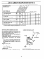
LUBRICATION
CHART
The warranty on this tiller does not cover items that have
been subjected to operator abuse or negligence.
To
receive full value from the warranty, operator must maintain tiller as instructed in this manual.
Some adjustments wilt need to be made periodically
properly maintain your tiller.
to
-- ENGINE
All adjustments in the Service and Adjustments section of
this manual should be checked at least once each
season.
Once a year you should replace the spark plug, dean
or replace air filter, and check tines and belt for wear.
A new spark plug and dean airfilter assure proper airfuel mixture and help your engine run better and last
longer,
BEFORE
EACH
USE
,
Check engine oil IeveL
•
•
Check tine operation.
Check for loose fasteners.
* IDL_
ARM
LUBRICATION
Keep unit well lubricated (See "LUBRICATION
-
• SAE 30 OR 10W30 MOTOR OIL
*" REFER TO CUSTOMER RESPONSIBILITIES
CHART").
12
"ENGINE"
sECTION.
,,,,,,, ,,,,,,,
CUSTOMEI
,
RESPONSIBILITIES
.,,1, ,,,1,.,.1,,
Disconnect
spark plug wire before performing
any maintenance
,1..
(except carburetor
J
1.11.
adjustment)
to prevent
Prevent fires! Keep the engine free of grass, leaves, spilled oil, or fuel. Remove fuel from tank before tipping
accidental
starting of engine°
unit for maintenance.
Clean muffler area of all grass, dirt, and debris.
Do not touch hot muffler or cylinder fins as contact may cause burns.
ENGINE
AIR CLEANER
Service air cfeanercartridge every twenty-five hours, more
often if engine is used in very dusty conditions.,
.
Loosen air cleaner screws, one on each side of cover.
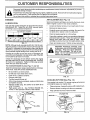
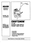
LUBRICATION
Use only high quality detergent oil rated with API service
classification SG1 Setect the oil's SAE viscosity grade
according to your expected temperature.
SAE VISCOSITY
]
_F
"C
1 t
-20"
0*
-30"
30°
-20"
TEMPERATURE
-10"
GRADES
'
' '
,,,t, t
32* 40"
60*
04
10"
RANGE ANT}CIPATED
8_"
20"
.
Remove air cleaner cover.
.
Carefully remove air cleaner cartridge, Be careful Do
not allow dirt or debris to fall into carburetor.
•
Clean by tapping gently on a flat surface,,
.
If very dirty, replace or wash in a nonsudsing detergent
and warm water solution. Rinse thoroughly with water
flowing from mesh side until water is ctear. Allow
cartridge to stand and air dry thoroughly before using_
=
Clean and reptace cover,, Tighten screws securely.
100"
30 °
(See Fig. 13)
40"
BEFORE NEXT OIL CHANGE
FIG. 11
NOTE: Although multi-viscosity oils (5W-30, 10W-30, etc.)
improve starting in cold weather, these multi-viscosity oils
will ..result in increased oil consumption when used above
32°_ (0°C). Check your engine oil love{ more frequently to
avoid possible engine damage from running _ow on oil.
CAUTION: Petroleum solvents,
such
as kerosene, are not to be used to clean
cartridge. They may cause deterioration of the cartridge.
Do not oil cartridge. Do not use pressurized air to
clean or dry cartridge.
Change the oil after the first two hours of operation and
every 25 hours thereafter or at teast once a year if the tiller
is not used for 25 hours in one year.
Check the crankcase oil level before starting the engine
and after each five (5) hours of continuous use. Add SAE
30 motor oil or equivalent. Tighten oil filler plug securely
each time you check the oil level.
AIR
COVER
SCREW
AIR
CLEANER
CARTRIDGE
TO CHANGE ENGINE OIL (See Figs. 11 and 12)
Determine temperature range expected before oil change°
All oil must meet API service c_assification SG,
•
Be sure tiiler is on level surface.
•
o
Oil will drain more freely when warm.
Catch oil in a suitable container.
,,
=
.
Remove drain plugo
Tip tilter forward to drain oilo
After oil has drained completely, replace oil drain plug
and tighten securely.
Remove oil filler ptug. Be careful not to allow dirt to
enter the engine.
Refill engine with oil. See "CHECK ENGINE OIL
LEVEL" in the Operation section of this manual
=
•
FIG. 13
COOLING
SYSTEM
(See Fig. 14)
Your engine is air cooled° For proper engine performance
and long life keep your engine clean.
°
Clean air screen frequently using a stiff-bristled brush°
o
Remove blower housing and clean as necessary.
-
Keep cylinder fins free of dirt and chaff°
!
CYUNDER
RNS
MUFFLER
OIL
DRAIN
PLUG
BLOWER
USING
\
SCREEN
OIL LEVEL
RLLER
PLUG
RG. 12
13
FIG. 14
CUSTO MER RESPONSIBILITIES
i
iii
MUFFLER
TRANSMISSION
Do not operate tiller without muffler. Do not tamper with
exhaust system. Damaged mufflers or spark arrestors
could create a fire hazard. Inspect periodically and replace
if necessary° If your engine is equipped with a spark
arrester screen assembly, remove every 50 hours for
cleaning and inspection. Replace if damage d .
Your transmission
if it is serviced.
SPARK
is sealed and will only require lubrication
CLEANING
PLUG
Replace spark plugs at the beginning of each tilling season
or afterevery 50 hours of use, whichever comes first. Spark
plug type and gap setting is shown in =PRODUCT SPECIFICATIONS" on page 3 of this manual.
-
Clean engine, wheels, finish, etc.. of all foreign matter°
,
Keep finished surfaces and wheels free of a{I gasoline,
oi!, etc_
•
Protect painted surfaces with automotive
type wax.
We do not recommend using a garden hose to clean your
unit unless the muffler, air' filter' and carburetor' are covered
to keep water' out. Water in engine can result in a shortened
engine life.
ERViCE AND ADJUSTMENTS
,, ,,,i,,
CAUTION: Disconnect
contact with plug.
spark plug wire from spark plug and place wire where it cannot come into
-.
N
TILLER
TINE
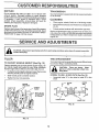
TO ADJUST
HANDLE
HEIGHT
Your outer tines can be assembled inseveral different ways
to suit your tilling or cultivating needs,
(See Fig. 15)
IA.................
I
Factory assembly has provided Iowest handle heighL Select handle height best suited for your tilling conditions.
Handle height will be different when tiller digs into soil.
•
If a higher handle height is desired, loosen the four nuts
secudng handle panel to engine brackets.
•
Slide handle panel to desired location.
•
Tighten the four nuts securely.
ARRANGEMENT
CAUTION:
Tines are sharp.
Wear
gloves or other protection when handling tines.
NORMAL TILLING - 26 INCH PATH (See Fig. 16)
•
Assemble holes "A" in tine hubs to holes "B" in tine
shaft..
ENGINE
BRACKETS
Jl 17k
J/
|
/
/
..,t
,_-"
PIN
CLEVIS
TINE
OUTER
..N=E
PANEL
//1
//
HAIRPIN
X_)
[7/
{
j
INNER "FINE
FIG. 16
/
!"
°
CLIP
.
FIG. 15
14
SERVICE
AND ADJUSTMENTS
FINAL CHECK "ON" POSITION
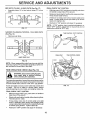
MID-WIDTH TILLING - 24 INCH PATH (See Fig. 17)
Assemble holes "A" in tine hubs to holes "C" in line
shafL
With tine control"ON" (held down to handle) push down
on handle to raise tines off the ground.
•
SlowIy pull recoil starter handle while observing tines.
Tines should rotate forward.
o
If tines do not rotate, inner wire of control cable is too
loose. Loosen cable clip and pull cable up to remove
slack and retighten clip_
=
Recheck in =ON" position and adjust if necessary
NOTE: if "ON" position check required adjustment, recheck "OFF" position adjustment to insure tines do not
rotate when control is "OFF" (up).
FIG_ 17
NARROW TILLING/CULTIVATING
=
- 12-3/4 INCH PATH
TINE CONTROL
(See Fig. 18)
.
Remove outer tines.
"OFF"
POSITION
BODY
o
TINE CONTROL
"ON" POSITION
o
CABLE CLIP
T1NE CONTROL
INNER TINES ONLY
FIG. t8
NOTE: When reassembling outer tines, be sure fight tine
assembly (marked "R") and left line assembly (marked "L")
are mounted to correct side of line shaft.
TINE OPERATION
i_
CHECK
(See Fig. 19)
from spark plug to prevent starting
WARNING:
Disconnectsparkplugwire
while checking
tine operation.
I
For proper line operation, forward tine control lever must be
against control body and all slack removed from inner wire
of control cable when control is in the "OFF" (up) position.
FIG. 19
If lever and cable are loose, ioosen cable clip at lower end
of cable.
Pull up on cable to remove slack, without
extending spring on end of cable, and retighten cable clip.
FINAL CHECK "OFF" POSITION
•
With tine control "OFF" (up), push down on handle to
raise tines off the ground.
•
Slowly pull recoil starter handle while observing tines.
Tines shouid not rotate.
o
if tines rotate, inner wire of control cable is too tight
which is extending lower spring and engaging tines.
Loosen cable cIipand push down on cable onty enough
to relieve spring tension. Tighten cable clip.
Recheck in "OFF" position and adjust if necessary,,
•
15
CABLE
SERVICE
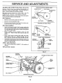
TO REPLACE
V-BELTS
(See Figs.
AND ADJUSTMENTS
20 and 21)
FORWARD MOTION (INSIDE) V-BELT
Replace V-belts if they have stretched considerably or if
they show cracks or frayed edges, There are two (2) Vbelts - forward (inside) and reverse (outside).
ENGINE
PULLEY
/
1
._
i*" '" \ I
BELT GUIDE
TRANSMISSION
/
PULLEY
Belt guard must be removed to service belts, See "TO
REMOVE BELT GUARD" in this section of manual°
NOTE: Observe carefully routing of both belts and location
of all belt guides before removing belts,
REVERSE
\
_.
"_
/
BELT REMOVAL
•
Remove reverse idler pulley from idler arm.
•
Remove reverse (outside) Wbelto
EELTGUtDE
•
Remove forward (inside) V-belt from transmission pulley first and then from engine pulley°
BELT REPLACEMENT
REVERSE
•
Install new forwatd (inside) V-belt to engine pulley first
then to transmission pulley, Be sure belt is positioned
on inside groove of both pulleys, inside all belt guides
and rests on idler pulley,
•
Before installing reverse (outside) V-belt. turn beIt
"inside out". Twist so wide, flat surface of belt is to
inside.
.
uWrap V-belt around reverse idler pulley and reassemble idler to idler arm, Tighten securely, Be sure
belt is between reverse idler pulley and idler arm pin.
•
PULLEY
PULLEY
_
(OUTSIDE)
FORWARD
IDLER PULLEY
V-BELT
IDLER PULLEY
FRONT VIEW REFERENCE
Install belt to outside groove of transmission pulley. Be
sure belt is inside all belt guides and tests on outside
groove of engine pulley,
REVERSE
IDLER
ARM PIN
CHECK T1NE OPERATION
•
See "FINE OPERATION
manual.
ENGINE
PULLEY
CHECK" in this section of
REPLACE BELT GUARD
FIG. 21
REVERSE
IDLER ARM
REVERSE
(OUTSIDE)
V-BELT
REVERSE
IDLER PULLEY
BELT
IDLER
ARM
BOLT
FORWARDMO_ON
(INSIDE) V-BELT
ENGINE
PULLEY
"TRANSMISSION
PULLEY
BELT GUIDE
FORWARD
IDLER PULLEY
FIG. 20
16
SERVICE
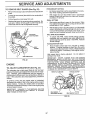
TO REMOVE
BELT
GUARD
AND ADJUSTMENTS
PRELIMINARY
(See Fig, 22)
SETTING
•
Remove two (2) cap nuts and washers from side of belt
guard.,
•
Air cleaner assembly must be assembled to the carburetor when making carburetor adjustments.,
•
Loosen (do not remove) tine shield nut on underside of
tine shield,,
°
•
Pull belt guard out and away from unit.
With engine off, turn idle needle valve in (clockwise)
closing it finger tight and then turn valve out (counterclockwise) 1-1/2 turns°
°
Replace belt guard by reversing above procedure. Be
sure slot in bottom of belt guard is under head of tine
shield bolt and all nuts are tightened securely°
FINAL SETTING
-
Start engine and allow to warm for five minutes. Make
final adjustments with engine running at idle and tine
control lever in "OFF" position,.
=
Y
With throttle control in"SLOVV_position, turn idle needle
valve in (clockwise) until engine begins to die then turn
out (counterclockwise) until engine runs rough. Turn
valve to a point midway between those two positions.
IDLE RPM ADJUSTMENT
CAP NUTS
•
_
WASHERS
ACCELERATION
TEST
•
Move throttle control lever from "SLOW" to "FAST"
position. If engine hesitates or dies,..t_m idle needle
valve out (counterclockwise) 1/8 turn. Repeat test and
continue to adjust, if necessary, until"engine accelerates smoothly,
High speed stop is factory adjusted. Do not adjust or
damage may result.
"
IMPORTANT:
NEVER TAMPER WITH THE ENGINE
GOVERNOR, WHICH IS FACTORY SET FOR PROPER
ENGINE SPEED. OVERSPEEDING THE ENGINE ABOVE
THE FACTORY
HIGH SPEED SETTING
CAN BE
DANGEROUS, IF YOU THINK THE ENGINE-GOVERNED
HIGH SPEED NEEDS ADJUSTING, CONTACT YOUR
NEAREST SEARS SERVICE CENTER/DEPARTMENT,
WHICH HAS PROPER EQUIPMENT AND EXPERIENCE
TO MAKE ANY NECESSARY ADJUSTMENTS.,
FIG. 22
ENGINE
TO ADJUST
CARBURETOR
To adjust idle RPM, rotate throttle linkage counterclockwise and hold against stop while adjusting idle
speed adjusting screw to obtain 1750 RPM. Release
throttle linkage.
(See Fig. 23)
The carburetor has a high speed fixed jet and has been
preset at the factory and adjustment should not be necessary. However, minor adjustments may be required to
compensate for differences in fue!, temperature, altitude or
load_ If the carburetor does need adjustment, proceed as
follows.
THROTTLE
LINKAGE
THROTTLE
STOP
In general, turning the idle needle valve in (clockwise)
decreases the supply of fuel to the engine giving a leaner
fuel/air mixture. Turning the needle valve out (counterclockwise) increases the supply of fuel to the engine giving
a richer fueVair mixture,
IMPORTANT:
DAMAGE TO THE NEEDLES AND THE
SEATS IN CARBURETOR MAY RESULT IF SCREWS
ARE TURNED IN TOO TIGHT.
IDLE SPEED
ADJUSTING SCREW
IDLE NEEDLE VALVE
FIG. 23
17
,ll ILl
,,ill
i
ii,,
ii
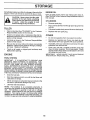
STORAGE
ENGINE
Immediately prepare your tiller for storage at the end of the
season or if the unit will not be used for 30 days or more_
,[,uuqu,u,,L
CAUTION:
Drain oil (with engine warm) and replace with clean oil.
(See"ENGINE" in the Customer ResponsibiIities section of
this manual).
HHH, N I
Never store the tiller
OIL
with
where
fumes
may
reach
an open
flame
gasoline
in the
tank
inside
a building
or spark.
Allow the engine to cool
before storing in any enclosure.
CYLINDERS
TILLER
•
Remove spark plug.
•
Pour I ounce (29 ml) of oil through spark plug hole into
cylinder.
•
Pull starter handle slowty several times to distribute oil.
•
Clean entire tiller (See "CLEANING" in the Customer
Responsibilities section of this manual).
•
Replace with new spark plug.
•
Inspect and replace belts, if necessary (See belt replacement instructions in the Service and Adjustments
section of this manual).
OTHER
•
Do not store gasoline from one season to_another_
•
Lubricate as shown in the Customer Responsibilities
section of this manual
•
Replace your gasoline can if your can starts to rust.
Rust and/or dirt in your gasoline will cause problems.
•
Be sure that all nuts, bolts and screws are securely
fastened. Inspect moving parts for damage, breakage
and wear Replace if necessary.
°
If possible, store your unit indoors and cover it to give
protection from dust and dirt.
•
Touch up all rusted or chipped paint surfaces;
lightIy before painting.
-
Cover your unit with a suitable protective cover that
does not retain moisture. Do not use plastic. Ptastic
cannot breathe which allows condensation to form and
will cause your unit to rust.
IMPORTANT:
NEVER COVER TILLER WHILE ENGINE
AND EXHAUST AREAS ARE STILL WARM°
sand
ENGINE
FUEL SYSTEM
IMPORTANT:
IT IS IMPORTANT TO PREVENT GUM
DEPOSITS
FROM FORMING IN ESSENTIAL
FUEL
SYSTEM PARTS SUCH AS THE CARBURETOR, FUEL
FILTER, FUEL HOSE, OR TANK DURING STORAGE.
ALSO, EXPERIENCE
INDICATES
THAT ALCOHOL
BLENDED FUELS (CALLED GASOHOL OR USING
ETHANOL OR METHANOl.) CAN ATTRACT MOISTURE
WHICH LEADS TO SEPARATION AND FORMATION OF
ACIDS DURING STORAGE. ACIDIC GAS CAN DAMAGE
THE FUEL SYSTEM OF AN ENGINE WHILE IN STORAGE.
•
Drain the fuel tank.
•
Start the engine and let it run until the fuel lines and
carburetor are empty.
•
Never use engine or carburetor cleaner products in the
fuel tank or pem_enent damage may occur.
Use fresh fuet next season.
•
NOTE:
Fuel stabilizer is an acceptable alternative in
minimizing the formation of fuel gum deposits during storage. Add stabilizer to gasoline in fuel tank or storage
container. Always follow the mix ratio found on stabilizer
container. Run engine at least 10 minutes after adding
stabilizer to allow the stabilizer to reach the carburetor. Do
not drain the gas tank and carburetor if using fuel stabilizer.
18
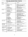
TROU
PROBLEM
LESHOOTING
POINTS
CAUSE
Will not start
Hard to start
CORRECTION
I,
I.
Out of fuel
2.
3,
4o
5
Engine not "CHOKED"
Engine flooded,
Dirty air cleaner_
Water in fuel
&
7
8.
9.
Clogged fuel tank
Loose spark plug wire,.
Bad spark plug or improper gap,
Carburetor out of adjustment.
1,
ThroNe control not set properly
2.
3o
4_
5.
6.
Dirty air cleaner.
Bad spark plug or improper gap.
Stale or dirty fuel,
Loose spark plug wire,
Carburetor out of adjustmenL
See "TO START ENGINE" in the Operation secfion
Wait several minutes before attempting to start.
Clean or replace air cleaner cartridge°
Drain fuel tank and carburetor, and refill tank with fresh
gasoline
& Remove fuel tank and clean.
7o Make sure spark plug wire is seated propedy on plug,
8, Replace spark plug or adjust gap,
9. Make necessary adjustments_
1,
2.
3,
4,
5o
6,,
H,,,.,
1.
2.
3o
4o
5o
&
7_
&
9,,
10,,
11.
12.
13.
Engine overheats
1o
2.
3.
4,
5,
Fill fuel tank
2,
3
4.,
5,
properly.
,,,,,,, ,,,,,,.,,
1.,
2,
&
4,
5,,
6.
7.
Engine is overloaded.
Dirty air cleaner.
Low oil level/dirty oil.
Faulty spark pfug,
Oil in fuel.
Stale or dirty fual.r
Water in fuel
Place thro_e control in 'FAST" position°
Clean ot reptace air cleaner cartridge
Replace spark pfug or adjust gap.
Drain fuel lank and raM! with fresh gasoline.
Make sure spark plug wire is seated propedy on plug.
Make necessary adjustments.
,i ,u
,.HU,I.,,,,
Set depth stake and wheels for shaJlower tilling,.
Ctaan or replace air cleaner cartridge,
Check oil leveVchanga oil.
Ctean and regap or change spark plug,,
Drain and clean fuel tank and refill, and clean carburetor.
Drain fuel tank and refill with fresh gasoline.
Drain fuel tank and carburetor, and refill tank with fresh
gasoline°
8_ Remove fuel tank and clean°
Clogged fuel tank.
Spark plug wire loose,,
Dirty engine air screen,,
Dirtytclogged muffler.
Carburetor out of adiustlnenL
Poor compress}one
9_
10,
11o
12.
13,,
1,
2.
3.
4,
Low oil lever!dirty oil
Dirty engine air screen.
Dirty engine.
Partially plugged muffler.,
Improper carburetor adjustment.
Connect and tighten spark plug wire.,
Clean engine air screen,
Clean/replace muffler,
Make necessary adjustments°
Contact an authorized service centertdepartment.
Check oil level/change oil,
Clean engine air screen_
Clean cylinder fins, air screen, muffler area.,
Remove and clean muffler.,
5_ Adiust carburetor
to richer position,,
1., Ground too dry and hard°
1.
Moisten ground or wait for more favorable
conditions.
2.
Wheels axed depth stake inoorrectly adjusted.
2.
Adjust wheels and depth stake
Sail baits up or clumps
1,
Ground tooweL
1o Wait for more favorable soil conditions.
Engine runs but tiller
won't move
1o Tine control is not engaged.
2.. V-belt not correctly adjusted.
3, V-belt is off pulley(s),.
1,, Engage tine control,
2,, Inspect/adjust V-belto
3, Inspect V-heR,
Engine rune but
when tilting
1. Tillingtoodeep°
2,, Throttlecontrolnot properlyadjusted.
3. Carburetorout of adjustment.
1., Set depth stake for shallower tilling°
2. Check thro_e control sstting.
3, Make necessary adjustments,
Excessive
bounce]
difficult handling
labors
19
soil
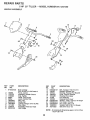
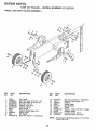
REPAIR PARTS
5HP
HANDLE
26" TILLER
- - MODEL
NUMBER
917.297350
ASSEMBLY
2
16
15
5
8
22
17
18
19
KEY
NO.
PART
NO.
1
STD533125
2
3
4
5
6
7
8
9
I0
11
12
136993
110512X
110632X
3066J
2635,.I
12000027
23200405
73970500
121145X
110514X
98000129
DESCRIPTION
KEY
NO,
13
14
15
16
17
18
19
20
21
22
23
24
Bolt, Carriage
5t16-18 UNC x 2-3/8 Grade 5
Panel, Control
Assembly, Handle Column
Grip, Handle
Cable, "line Control
Lever, Control, "line
Ring, Clip
Screw, Set
Locknut, Flange 5/16-18 UNC
Clip, Cable
Assembly, Panel and Tube
Nut, Flange
PART
NO.
STD533107
136998
137640
106932X
101248K
1778E
137056
STD551037
STD56t210
STD560907
19090814
72010520
NOTE:
2O
DESCRIPTION
Belt, Carriage 5116-18 x 3/4
Bracket, Reverse Rod
Bushing, Reverse Rod Bracket
Knob, Control, Reverse
Reverse Rod, Upper
Pin, Retaining
Reverse Rod, Lower
Washer 13/32 x 13/16 x 16 Gauge
Pin, Cotter 1/8 x 3/4
Pin, Cotter 3/32 x 1/2
Washer 9/32 x 1/2 x 14 Gauge
Bolt 5/16-18 x 2-1/2
All component dimensions
t inch = 25.4 mm
given in U.S. inches.
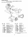
REPAIR
PARTS
5 HP
BELT
GUARD
AND
26" TILLER
PULLEY
-- MODEL
NUMBER
91"7.297350
ASSEMBLY
8
29
1 _
10
11
12
17
24
23
22
KEY
NO.
1
2
3
4
5
6
7
8
9
10
'11
12
13
14
15
16
PART
NO,
123643X
g484R
86777
74770812
STD541037
19131316
2009J
127180X
7476O628
106970X459
STD551025
104213X
72140405
133035
2614J
23230506
'?.
21
18
DESCRIPTION
Assembly, Bracket, Belt Guard
C_ip, Cable
Screw, Hex Washer Head, Slotted,
Thread Cutting #10-24 x 1/2 Type D
Bolt, Hex Head 1/2-20 x 3/4
Nut, Hex 3/8-16
Washer 13/32 x 13/16 x 16 Gauge
Pulley, Idler, Reverse
Assembly, Arm, Reverse Idler
Bo_t, Hex Head 3/8-16 x 1-3/4
Guard, Belt
Washer 9/32 x 5/8 x 16 Gauge
Nut, Cap 1/4- 20
Bolt, Carriage 1/4-20 x 5/8
V-Belt (Forward Motion)
V..Belt (Reverse)
Screw, Set, Socket, Headless
CoP. 5/16..18 x 3/8
KEY
NO.
PART
NO,
17
18
19
20
21
22
23
24
25
26
27
28
29
30
2649M
2607J
110550X
12000035
STD541237
9178R
674A30
STD523712
106968X
73350500
STD541025
STD551125
t09227X
23200404
31
101189L
NOTE:
21
DESCRIPTION
Key, Square
Sheave, Transmission
Bott, Belt Guard
Ring, Klip
Nut, Hex, Jam 3/8-16
Pultey, Idler
Arm, Idler
Bolt, Hex Head 3/8-16 x 1..1/4
Shaft, Idler Arm
Nut, Hex, ,,'am 5/16-18
Nut, Hex 1/4-20
Washer, Lock 1/4
Pad, Idler
Screw, Set, Socket, Headless
C.P. 1/4-20 x 1/4
Sheave, Engine
All component dimensions given in U.S. inches.
1 inch = 25.4 mm
REPAIR PARTS
5 HP 26" TILLER
WHEEL
AND DEPTH
STAKE
NUMBER
917.297350
ASSEMBLY
1
17
- - MODEL
2
19 20
20
19
18
16
17
KEY
NO.
PART
NO.
1
2
3
4
5
6
7
8
9
10
tl
9194R
74760520
STD523107
STD541031
STD551131
STD541537
4921H
1952J
122233X
326J
STD623715
DESCRIP_ON
Pin, Clevis
Bolt, Hex Head 5/16-18 x 1-1/4
Bolt, Hex Head 5/16-18 x 3/4
Nut, He× 5/16-18
Washer, Lock 5/16
Locknut 318-24
Clip, Hairpin
Support, Depth Stake, R.H.
Stake, Depth
Pin, Clevis
Bolt, Hex 3!8-24 x 1-1/2 Grade 5
KEY
NO.
PART
NO.
12
13
14
15
16
17
18
19
20
21
74760524
1951J
120958X
5388,3
121117X
9188R
STD551037
9190R
STD541437
74760516
NOTE:
22
DESCRIPTION
Bolt, Hex 5116-18 x 1-1/2 Grade 2
Support, Depth Stake, L.H.
Washer
Spr_ng, Stake
Belt, Shoulder
Wheel
Washer 13/32 x 13/16 x 11 Gauge
Bracket, Wheel
Locknut, Crown 318-16
Bolt, Hex Head 5/16-18 x I
Allcomponent dimensions
1 inch = 25.4 mm
given in U.S. inches.
REPAIR PARTS
5HP
26" TILLER
-- MODEL
NUMBER
917.297350
TINE ASSEMBLY
2
i
t
2
3
/
/
2
6
6
6
I
6
KEY
NO.
PART
NO.
1
2
3
100746M
STD624008
674A43
DESCRIPTION
KEY
NO.
Tine, Outer, R_H.
Clip, Hairpin
Tine, Inner, R.H+
4
5
6
23
PART
NO.
674A42
100744M
4929H
DESCRIPTION
Tine, Inner, L.Ho
Tine, Outer, L.H.
Pin, Clevis
REPAIR PARTS
5 HP 26" TILLER
- - MODEL
NUMBER
917.297350
TRANSMISSION
2O
1
14
14
_.
15
10
14
12
KEY
NO.
PART
NO.
1
2
3
4
5
6
7
8
9
10
11
12
74760524
STD623732
STD551037
STD551137
7810H
g057R459
1949J
110519X
STD551131
STD541031
74760544
126669X
DESCRIPTION
Bolt, Hex 5/16-18 x 1-1/2 Grade 2
Bolt, Hex 3/8-24 x 3-1/4 Grade 5
Washer 13/32 x 13/16 x 1t
Washer, Lock 3/8
Locknut 3/8-24
Shield, Tine
Bracket, Engine, R.H.
Bracket, Engine, L.H.
Washer, Lock 5/16
Nut, Hex 5/16-18
Bolt, Hex Head 5/16-18 x 2-3/4
Transmission
KEY
NO.
PART
NO.
13
14
15
16
17
18
19
20
19171616
9173R
STD541431
19091412
19092016
STD551125
74610412
137263
NOTE:
24
DESCRIPTION
Washer t7/32 x 1 x 16 Gauge
Spacer, Split
Nut, Hex, Keps 5/16-18 UNC
Washer 9/32 x 7/8 x 12 Gauge
Washer 9/32 x 1-1/4 x 16 Gauge
Washer, Lock 1/4
Bolt, Hex 1/4-.28 x 3/4 Grade 5
Engine, Bdggs & Stratton, 5 HP,
Model No. 135202, Type 0119-01
All component dimensions given in U_S, inches,
1 inch = 25.4 mm
REPAIR PARTS
5 HP 26" TILLER
- - MODEL
NUMBER
917.297350
DECALS
7
O
KEY
NO.
1
2
3
4
5
6
7
8
--
PART
NO.
137"742
133026
137737
137653
12043't X
t10719X
132402
t20075X
140435
140436
DESCRIPTION
Decal, Logo
Decal, Logo
Decal, Logo
Decal, Caution, T]ne Control
Decal, Hand Placement
Decal, Operation and Lubrication
Decal, HP
Decal, Warning, Rotating Tines
Manual, Owner's (English)
Manual, Owner's (Spanish)
25
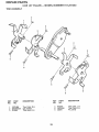
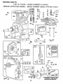
REPAIR PARTS
5 HP 26" TILLER
BRIGGS
& STRATTON
- - MODEL
ENGINE - - MODEL
NUMBER
NUMBER
917.297350
135202, TYPE NO, 0119-01
14
869
m+
13
"k 871
307
_ 870
36 35
306
_
_
40
308
40
7
552
10
529
527
528
12
20
21
INSTRUCTION
26
MANUAL
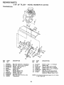
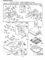
REPAIR PARTS
5 HP 26" TILLER
BRIGGS
& STRA_ON
- -MODEL
ENGINE - - MODEL
NUMBER
NUMBER
917.297350
135202, TYPE NO. 0119-01
52
392
432
_ 435
433
256 ,_
1012
414
153
542
968
190A
_'_
967
191
208
209
916
2,23
27
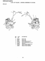
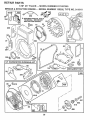
REPAIR PARTS
5 HP 26" TILLER
BRIGGS
& STRATTON
- - MODEL
ENGINE - - MODEL
NUMBER
NUMBER
917.297350
135202, TYPE NO. 0119-01
L
"k' REQUIRES SPECIALTOOLS
TO INSTALL SEE REPAIR
INSTRUCTION MANUAL.
334
73
23 '
24
200
52
7
332
455
i,iu
9
305
3
llIHH=
121 CARBURETOR
OVERHAUL
KIT
163
(_
191
19
358 GASKET
SET
52
/l
394
65
_373
57
1016
461
69A
515
58
_59
28
69
456
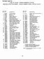
REPAIR PARTS
5 HP
BRIGGS
KEY PART
NO. NO.
1
2
3
5
7
8
9
10
11
12
13
14
15
16
18
19
20
21
22
23
24
25
26
27
28
29
30
32
33
34
35
36
37
395990
297565
299819
214040
272157
495774
27549
94621
66578
270080
270125
270126
94221
94679
93448
94387
492088
230978
297602
495660
294606
66768
94682
297229
222698
298904
298905
298906
298907
298982
299742
298983
298984
298985
26026
298909
298908
299430
390459
221890
94745
211119
261044
260552
26478
222443
26" TILLER
& STRATf'ON
- - MODEL
NUMBER
ENGINE - - MODEL NUMBER
KEY PART
NO. NO.
DESCRIPTION
Cylinder Assembly
Bushing, Cylinder
"Seal, Oil
Head, Cylinder
• Gasket, Cylinder Head
Breather Assembly
* Gasket, Valve Cover
Screw, Breather Mounting
Grommet, Breather Tube
"Gasket, Crankcase, Standard .015"
"Gasket, Crankcase .005"Thick
"Gasket, Crankcase ..009" Thick
Screw, Cylinder Head 2-3132"
Screw, Cylinder Head 2_15t32"
Plug, Pipe, Hex Socket
Plug, Oil Drain
Crankshaft
Gear Pin, Crankshaft
Cover Assembly, Crankcase
Bushing, Crankcase Cover
* Seal, Oil
Plug, Oil Filler
Screw, Cover Mounting
Flywheel, Magneto
Key, Flywheel
Piston Assembly, Standard Size
Piston Assembly .010" Oversize
Piston Assembly .020" Oversize
Piston Assembly .030" Oversize
Ring Set, Piston, Standard Size
Ring Set, Piston, Standard, Chrome
Ring Set, Piston o010" Oversize
Ring Set, Piston ,020" Oversize
Ring Set, Piston .030" Oversize
Lock, Piston Pin
Pin Assembly, Piston, Standard
Pin Assembly, Piston .005" Over
Rod Assembly, Connecting
Rod Assembly, Connecting
.020" Undersize Crankpin Bore
Dipper, Connecting Rod
Screw, Connecting Rod
Valve, Exhaust
Valve, Intake
Spring, Intake Valve
Spring, Exhaust Valve
Guard, Flywheel
40
93312
45
46
52
55
56
57
58
260642
212733
271936
494846
493824
262594
280406
59 396892
60 393152
65 94686
69 280973
69A 224322
73 224632
81 222263
90 495426
95 93499
96 223793
97 490048
108 491177
118 23t533
121 495606
124 94616
127 220352
127A 223789
149 26336
152 260575
153 490589
154 93527
163 271935
180 495405
181 494559
190 94712
190A 94677
191 272489
200 223886
202 262270
203 280720
"
"*
"*
135202,
NO. 0119-01
DESCRIPTION
Retainer, Intake Valve and Exhaust
Spring
Tappet, Valve
Gear, Cam
"'" Gasket, Carburetor Mounting (2)
Housing, Rewind Starter
Pulley, Rewind Starter
Spring, Rewind Starter
Rope, Rewind Starter
(Cut to Required Length)
Insert, Starter Handle
Handle, Rewind Starter
Screw, Housing Mounting
Washer
Washer
Screen, Rotating
Lock, Screw
Carburetor Assembly
Screw, Throttle Valve to Shaft
Throttle, Carburetor
Shaft and Lever, Throttle
Valve and Shaft Group, Choke
Valve, Needle
Carburetor Overhaul Kit
Screw, Hex Head
Plug, Welch
Plug, Welch
Spring, Needle Valve
Spring, Throttle Adjustment
Screw and Collar
Screw, Machine, Round Head
• Gasket, Air Cleaner Mounting
Tank Assembly, Fuel
Cap, Fuel Tank
Screw, Fuel Tank
•
4"
... Screw, Fuel Tank Mounting 1-3/
Gasket, Fuel Tank to Carburetor
Guide, Air
Link, Throttle
Bell Crank
Included in Gasket Set (495603)
Included in Carburetor Overhaul Kit (495606)
included in both Gasket Set (495603), and
Carburetor Overhaul Kit (495606)
NOTE:
29
917.297350
All component dimensions given in UoS_inches
1 inch = 25.4 mm
iiii
ill,,,llll i
SERVICE
, i, ,i
illllll,
ii
ii
i
i
[
NOTES
N,,
illlllllll
i
IL, L JL I,II,,I,
IuIJ
_
m-i illl,llll
,,,=
=i ,,iilll
,m
[RI:IFTgMRNo
OWNER'S
MANUAL
MODEL NO.
917.297350
5.0 HP
26 INCH TINE WIDTH
FRONT TINE TILLER
Each tiiler has its own model number_ Each engine has its own model
number,
The model number for your tiller will b_ found on a plate attached to the
right hand engine bracket.
The model number for your engine will be found on the blower housing of
the engine adjacent.
All parts listed herein may be ordered from any Sears, Roebuck and Co.
Service Center/Department and most Retail Stores.
HOW TO ORDER
REPAIR PARTS
WHEN ORDERING REPAIR
ING INFORMATION:
PARTS, ALWAYS
GIVE THE FOLLOW-
PRODUCT - FRONT TINE TILLER
• MODEL NUMBER - 917.297350
• ENGINE MODEL NUMBER - 130202, TYPE NUMBER 011901
• PART NUMBER
- PART DESCRIPTION
Your Sears merchandise has added value when you consider Sears has
service units nationwide staffed with Sears trained technicians.., professional technicians specifically trained to insure that we meet our pledge
to you, we service what we sell.
Sears, Roebuck and Co., Hoffman Estates, IL 60179 U.S.A.
HH
140435
6.25_93
=
=
HH,===,=
I
::::::::::::::::::::::::::::::::
= =HH
I= =
PRINTED
IN U,S,A.