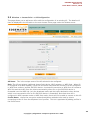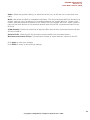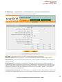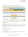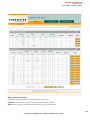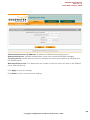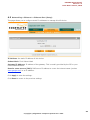
1
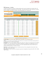
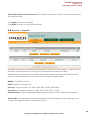
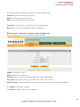
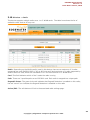
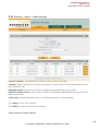
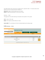
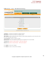
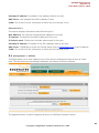
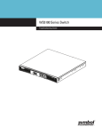
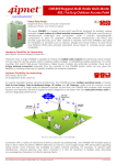
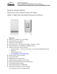
EAP3030/1- I User Documentation
Users Manual
Version 1.2
Edgewater Computer Systems, Inc.
Copyright © Edgewater Computer Systems Inc. 2010
EAP3000 Users Manual
Version: 1.2
Issue Date: June 12, 2010
EAP3000 Users Manual
Version 1.2
Revision History
Date
Version
Description
Author
Jan. 15, 2009
0.1
Preliminary
Edgewater
Dec. 8, 2009
0.2
Added images and corrections
Edgewater
Mar. 15, 2010
1.0
Corrections
Edgewater
May 30, 2010
1.1
Added Images
Edgewater
June 12, 2010
1.2
Amended Images
Edgewater
Copyright © Edgewater Computer Systems Inc. 2010
2
EAP3000 Users Manual
Version: 1.2
Issue Date: June 12, 2010
Table of Contents
1
2
3
4
5
Revision History....................................................................................................... 2
QuickStart .............................................................................................................. 4
Login...................................................................................................................... 7
Wireless ................................................................................................................. 8
3.1
Wireless -> Access Point ................................................................................. 8
3.2
Wireless -> Access Point -> AP Configuration ................................................... 10
3.3
Wireless -> Access Point -> AP Configuration -> Advanced Configuration............. 12
3.4
Wireless -> Access Point -> AP Configuration -> Access Control ......................... 14
3.5
Wireless -> Profiles ...................................................................................... 16
3.6
Wireless -> Profiles -> Profile Configuration ..................................................... 17
3.7
Wireless -> Profiles -> Profile Configuration -> Advanced Profile Configuration ..... 19
3.8
Wireless -> RogueAP ................................................................................... 20
3.9
Wireless -> RogueAP -> Authorized AP Configuration ....................................... 21
3.10
Wireless -> Radio ....................................................................................... 22
3.11
Wireless -> Radio -> Radio Settings .............................................................. 23
3.12
Wireless -> Card......................................................................................... 24
3.13
Wireless -> Card -> Edit WLAN Card Settings ................................................. 25
3.14
Wireless -> Statistics .................................................................................. 26
3.15
Wireless -> Radius ...................................................................................... 29
3.16
Wireless -> Radius -> Radius Configuration .................................................... 29
Networking ........................................................................................................... 31
4.1
Networking -> Ethernet ................................................................................ 31
4.2
Networking-> Ethernet -> Ethernet Port (Setup) .............................................. 32
Management -> Status ........................................................................................... 33
5.1
Management -> Utilities................................................................................ 35
5.2
Management -> Diagnostics .......................................................................... 37
5.3
Management -> System Time ........................................................................ 39
5.4
Management -> Logs.................................................................................... 40
5.5
Management -> Logs -> Event Logs ............................................................... 42
Copyright © Edgewater Computer Systems Inc. 2010
3
EAP3000 Users Manual
Version: 1.2
Issue Date: June 12, 2010
1
QuickStart
1. The unit can be powered one of two ways either with the supplied AC adapter or with PoE
(Power over Ethernet) enabled 10/100 Ethernet cable into the RJ45 jack as illustrated in
Figure 1
2. Mount EAP3030/1-I on wall mount using the wall mounting plate as shown in Figures 2 to 4
or as required on a flat surface.
3. After applying power to the unit allow 30 seconds for software boot-up.
4. Log into unit.
Power Adapter
receptacle
Ethernet &
optional PoE
Figure 1 - Power and Ethernet Rear-panel Connections
Copyright © Edgewater Computer Systems Inc. 2010
4
EAP3000 Users Manual
Version: 1.2
Issue Date: June 12, 2010
Figure 2 – Mounting Plate
Figure 3 – Mounting Plate Bottom Clip
Copyright © Edgewater Computer Systems Inc. 2010
5
EAP3000 Users Manual
Version: 1.2
Issue Date: June 12, 2010
Figure 4 – Mounting Plate Top Clip
Figure 5 – EAP3031 on Mounting Plate
Copyright © Edgewater Computer Systems Inc. 2010
6
EAP3000 Users Manual
Version: 1.2
Issue Date: June 12, 2010
2
Login
Welcome to the Edgewater EAP3000
The login page authenticates users and ensures that only authorized users can view or modify this
device’s settings.
Login username and password
The device accepts two types of logins, one with administrative privileges and one with guest
privileges. With administrative privileges, you can view and also modify the configuration of the
access point. Logging in with guest privileges will only allow you to view the existing configuration,
but not to change it.
Enter the username and password on this page to login to the router and view/edit its
configuration. The default user names are mentioned on the label at the bottom of the router.
Session Timeout
Once logged in, the router will maintain a session for the login. If there is no modification or access
for a specified period, the session will expire and you will be asked to login again. The default idle
session time is five minutes, but can be changed by logging in and updating the timeout value in
the Management -> Users page.
Copyright © Edgewater Computer Systems Inc. 2010
7
EAP3000 Users Manual
Version: 1.2
Issue Date: June 12, 2010
3
Wireless
3.1 Wireless -> Access Point
The AP table displays the list of configured Access Points for this device. From this summary list,
status and parameters of each AP are available for display or configuration.
! (Status): An AP can be disabled if not in use and enabled as needed. The AP is disabled if the
status light is grey and it is enabled if the status light is green. Disabling an AP does not delete the
configuration, but stops the AP. Enabling the AP creates a wireless network where computers and
other devices can join and communicate with the devices connected to the access point or the
devices on the local area network (LAN).
AP Name: This is AP identifier which uniquely identifies AP in the list of configured APs.
SSID: the name or SSID (service set identifier) is the name of the wireless network serviced by
this AP; it is configured on the Profile page and later associated with AP by selecting it from the
profile drop down box. Note that a given wireless profile can be common to multiple APs, and so
the SSID is not unique to an AP. In order for the computers or devices to communicate via this
Copyright © Edgewater Computer Systems Inc. 2010
8
EAP3000 Users Manual
Version: 1.2
Issue Date: June 12, 2010
wireless network serviced by this AP, all devices must select the same SSID from the list of
wireless networks in the area.
Broadcast: The icon here indicates whether SSID is broadcasted or not in the beacon frames
transmitted by the AP. If SSID is not broadcast then wireless devices will not be able to see the
network name (SSID). The green tick mark indicates that the AP’s SSID is broadcasted to the
public; the red ‘cancel’ icon indicates the SSID is not broadcasted and a device would have to
specify the SSID exactly to connect to this AP.
Profile: This field has a brief description of the security, encryption and authentication combination
assigned to the AP. A Profile is not necessarily unique to an AP; rather this grouping of wireless
settings can be used on more than one AP at the same time.
Radio: The physical radio(s) on which this AP is running on. An AP can run on multiple radios at
the same time for load-balancing and better throughput.
VLAN: The AP can be part of a logical network defined by the VLAN id; this allows devices
connected to the VLAN through this AP to exchange data with one another as in a LAN.
Action/Edit: The edit button will link to the AP Configuration page, allowing you to change the
profile, radio, mode, etc. that is used by this AP.
Action/Status: The status button will link to a statistics page for this AP, displaying traffic
statistics for the AP and the list of the connected clients.
The actions that can be taken on APs are:
Select All: Select all the APs in the table
Enable: Enable the selected APs
Disable: Stops the selected APs
Delete: Stops and deletes the selected AP or APs
Add: Add a new AP
Copyright © Edgewater Computer Systems Inc. 2010
9
EAP3000 Users Manual
Version: 1.2
Issue Date: June 12, 2010
3.2 Wireless -> Access Point -> AP Configuration
This page allows you to add a new AP or edit the configuration of an existing AP. The details will
then be displayed in the AP table on the main Access Points page under the Wireless menu.
AP Name: This is the unique name of the AP selected to be configured.
Role: The AP can act as a traditional Access Point device, WDS repeater, or WDS Root. When AP
is configured as a WDS repeater, it acts like a wireless client and can connect to an AP configured
in WDS Root mode on another EAP3000 device. A successful connection to WDS Root AP creates a
WDS link and the traffic from the clients connected to other APs on this EAP3000 device is
forwarded over the WDS link (only the broadcast traffic and the traffic destined to other devices
which is not connected to APs on this EAP3000 device is forwarded). Note that when AP is
configured in WDS repeater mode or WDS Root mode, clients will not be able to connect to this AP.
Profile Name: choose the encryption and authentication methods to be used by clients
connecting to this AP from the dropdown list of profiles. This list is populated by adding profiles in
the Profile menu.
Copyright © Edgewater Computer Systems Inc. 2010
10
EAP3000 Users Manual
Version: 1.2
Issue Date: June 12, 2010
Radio: Select the physical radio(s) on which this AP will run; an AP can run on more than one
radio.
Mode: this selects the 802.11 modulation technique. This device supports 802.11b and 802.11g
modes. Select g only if all devices in the wireless network can support 802.11g. Select b only
mode if other devices and computers in the network can only support 802.11b. Select g and b if
there will be some devices in this wireless network that will use 802.11g and some that will use
802.11b.
VLAN Enabled: Select this check box to tag the traffic received from connected clients with this
AP with a VLAN id.
Default VLAN: VLAN id which will be used to tag the traffic from connected clients.
Maximum Associated Clients: The maximum number of clients that can connect to this AP.
Click Apply to save your changes.
Click Reset to revert to the previous settings.
Copyright © Edgewater Computer Systems Inc. 2010
11
EAP3000 Users Manual
Version: 1.2
Issue Date: June 12, 2010
3.3 Wireless -> Access Point -> AP Configuration -> Advanced Configuration
This page is used to specify advanced configuration details.
AP Name: This is the name of the AP that was selected to be configured.
Beacon Interval: enter the amount of time in milliseconds between beacon transmissions.
Dtim Interval: this interval sets when the delivery traffic indication message is sent; related to
beacon interval.
RTS Threshold: the Request to Send (RTS) threshold is the value the AP checks against its
transmitting frames to determine if the RTS/CTS handshake is required with the receiving client.
Using a small value causes RTS packets to be sent more often, consuming more of the available
bandwidth, therefore reducing the apparent throughput of the network packet. The default is
2346, which effectively disables RTS.
Fragmentation Threshold: this is the maximum length of the frame, beyond which packet must
be broken up (fragmented) into two or more frames. Collisions occur more often for long frames
Copyright © Edgewater Computer Systems Inc. 2010
12
EAP3000 Users Manual
Version: 1.2
Issue Date: June 12, 2010
because sending them occupies the channel for a longer
disables Fragmentation.
The default is 2346, which effectively
Preamble mode: 802.11b requires that a preamble be prepended to every frame before it is
transmitted to the air. That preamble may be either the traditional "long" preamble, which requires
192 µs for transmission, or it may be an optional "short" preamble that requires only 96 µs. Long
preamble is needed for the compatibility with legacy 802.11 systems operating at 1 and 2 Mbps.
The default is “long”.
RTS/CTS protection: select to always do RTS/CTS handshake before transmitting a packet; it is
generally used to minimize collisions among hidden stations
Transmit Power Gain: define the relative amplification (gain) in dbm for transmitted packets
which is added to the TX power configured on the physical radio.
Retry Limit: This limits the number of retries the AP will use when a frame transmission fails. It is
used for both long and short frames, of size less than or equal to the RTS threshold.
Supported Rate: Select the rate or rates (in Mbps) which AP will advertise in the beacon frames;
at least 1 checkbox must be selected.
Click Apply to save your changes.
Click Reset to revert to the previous settings.
Copyright © Edgewater Computer Systems Inc. 2010
13
EAP3000 Users Manual
Version: 1.2
Issue Date: June 12, 2010
3.4 Wireless -> Access Point -> AP Configuration -> Access Control
This page allows you to define specific MAC addresses to permit or deny connections to the
selected AP. The default is “open” access, which does no filtering on specific MAC addresses.
Default ACL Policy
AP Name: This is the name of the AP that is being configured.
ACL Policy Status: Select between Allow, Deny, or Open. Allow would only permit MAC addresses
in the List below to connect to the AP. Deny would prevent any clients with a MAC address in the
List below to connect to the AP. Open allows any clients to connect and does not filter using the
list of MAC addresses below.
Click Apply to save your changes.
Click Reset to revert to the previous settings.
List of MAC Addresses
This list shows all the MAC addresses of computers and devices which is authorized/unauthorized
(based on the default ACL Policy) to connect to this access point.
Copyright © Edgewater Computer Systems Inc. 2010
14
EAP3000 Users Manual
Version: 1.2
Issue Date: June 12, 2010
Select All: Select all the MAC addresses in the list
Delete: Delete the selected MAC address or addresses from the list
Add New Station Manually: enter the MAC address of the client that you would like to add to the
list of MAC address above.
Copyright © Edgewater Computer Systems Inc. 2010
15
EAP3000 Users Manual
Version: 1.2
Issue Date: June 12, 2010
3.5 Wireless -> Profiles
A profile is a definition of generic wireless settings which can be shared across multiple APs. APspecific settings are configured from the AP page. The profile allows for easy duplication of SSIDs,
security settings, encryption methods, client authentication, etc. across APs.
Profile Name: this is the unique (alphanumeric) identifier of this wireless profile.
SSID: this is the Service Set Identifier that clients use to connect to the AP that has this profile; it
is referenced in the AP tables and statistics.
Broadcast: The icon here indicates whether this profile will configure the assigned AP to broadcast
its SSID or not.. The green tick mark indicates that SSID is marked to be broadcasted; the red
‘cancel’ icon indicates the SSID is marked to not to be broadcasted and a device would have to
specify the SSID exactly to connect to the AP.
Security: this field displays the type of wireless security (if any) assigned to this profile: None,
WEP, WPA, WPA2, WPA+WPA2
Encryption: this field selects the encryption type that is assigned to the profile: WEP, TKIP, CCMP,
TKIP + CCMP.
Copyright © Edgewater Computer Systems Inc. 2010
16
EAP3000 Users Manual
Version: 1.2
Issue Date: June 12, 2010
Authentication: if any client authentication is required to allow the AP with this profile to establish
a connection, it will be displayed here: PSK, RADIUS, PSK + RADIUS.
Action/Edit: The edit button will link to the Profile Configuration page, allowing you to change the
properties shown in the table for this Profile.
The actions that can be taken on profiles are:
Select All: Select all the profiles in the table
Delete: Delete the selected profile or profiles
Add: create a new profile and add it to the list
3.6 Wireless -> Profiles -> Profile Configuration
The Profile Configuration page allows you to define the identifiers and wireless settings of a
particular profile.
Profile Name: enter a unique (alphanumeric) identifier of this wireless profile.
SSID: define the Service Set Identifier that clients use to connect to the AP that has this profile; it
is referenced in the AP tables and statistics.
Copyright © Edgewater Computer Systems Inc. 2010
17
EAP3000 Users Manual
Version: 1.2
Issue Date: June 12, 2010
Broadcast SSID: enable this checkbox to broadcast the SSID. Disable this box to prevent autodetection of the SSID and force clients wishing to connect to this AP to specify the SSID without
seeing it as a detected network.
Security: Choose the type of security to be configured in this profile:
None: No security. Any wireless device can connect (subject to AP ACL policy).
WEP (Wired Equivalent Privacy): . Select this to use WEP encryption on the data packets.WEP
is not considered to be secure and can be easily broken. Select this only if there are clients which
can only support WEP security.
WPA (Wi-Fi Protected Access): WPA is part of wireless security standard (802.11i)
standardized by the Wi-Fi Alliance and it was intended as an intermediate measure to take the
place of WEP while 802.11i was prepared. It supports TKIP/CCMP encryption (default is TKIP) and
PSK/RADIUS based authentication.
WPA2:WPA2 is implementation of security standard specified in final 802.11i. . It supports
TKIP/CCMP encryption (default is CCMP) and PSK/RADIUS based authentication.
WPA and WPA2 This mode allows both WPA and WPA2 clients to connect simultaneously.
Encryption: Select the encryption method to use: TKIP, CCMP, or both.
Authentication: Type of authentication to use: RADIUS, PSK, or PSK + RADIUS.
WPA Password: Pre-Shared key for WPA/WPA2 PSK authentication. The clients also needs to be
configured with the same password.
WEP Index and Keys
Selecting WEP in the Security box requires selecting the type of authentication and specifying the
static WEP key to be used in the computers or devices that wish to access this secured wireless
network.
Authentication: select between Open System or Shared Key schemes
Encryption: select the encryption type: 64 WEP, 128 WEP, or 152 WEP. The larger size keys
provide stronger encryption, thus making the key more difficult to crack (i.e. 64 WEP has a 40 bit
key which is less secure than the 128 WEP which has a 104 bit key).
WEP Passphrase: choose any alphanumeric phrase (longer than 8 characters for optimal
security) and click generate key to generate 4 unique WEP keys. Select one of the four to use as
the static key that devices must have in order to use the wireless network.
WEP Key 1-4: If WEP Passpharase is not specified, a key can be entered directly in one of the
WEP Key boxes. The length of key should be 5 ASCII characters (or 10 hex characters) for 64-bit
WEP, 13 ASCII characters (or 26 hex characters) for 128-bit WEP, and 16 ASCII characters (or 32
hex characters).
WEP Key Index: Based on which WEP key box is used, WEP key index is derived. Different clients
can have different numbering scheme for index. For clients which have indexing starting with 0,
WEP Key 1 to WEP Key 4 corresponds to index 0 to 3. Clients which have indexing starting with 1,
WEP Key 1 to WEP Key 4 corresponds to index 1 to 4.
Copyright © Edgewater Computer Systems Inc. 2010
18
EAP3000 Users Manual
Version: 1.2
Issue Date: June 12, 2010
Click Apply to save your changes.
Click Reset to revert to the previous settings.
3.7 Wireless -> Profiles -> Profile Configuration -> Advanced Profile Configuration
This page allows you to edit configuration parameters from their default settings.
Association Timeout Interval (Seconds): This specifies the timeout interval between
authenticated and associated state of client. If client is not associated in this interval after the
authentication, it is disconnected.
Authentication Timeout Interval (Seconds): This is the timeout interval for RADIUS (802.1X)
authentication. If RADIUS authentication is not completed within this time after client is associated,
it is disconnected.
Group Key Refresh Interval (Seconds): This specifies the timeout interval after which group
keys are generated (only used if profile is configured with WPA or WPA2 security).
PMKSA Life Time (Seconds): WPA2 security standard has a option called PMKSA caching which
means that the masker keys derived from successful RADIUS authentication are cached for some
time to avoid long RADIUS authentication every time a client connects. This timeout interval
specifies for how long this PMKSA is stored in the AP A client reconnecting within this interval
(after successful RADIUS authentication) can skip the RADIUS authentication.
Copyright © Edgewater Computer Systems Inc. 2010
19
EAP3000 Users Manual
Version: 1.2
Issue Date: June 12, 2010
802.1X Re-authentication Interval: The timeout interval after which AP should re-authenticate
with RADIUS server.
Click Apply to save your changes.
Click Reset to revert to the previous settings.
3.8 Wireless -> RogueAP
This page summarizes the authorized and rogue APs configured for the system. A rogue AP is the
AP that is not authorized to be running in the wireless area covered by this AP(s).
An Administer can specify the list of authorized Access Points in the area in the “Authorized AP”
table. Any AP detected which is not in this list is recorded in RogueAP table.
BSSID: The BSSID of the AP
SSID: The SSID serviced by AP
Security: Security used by AP: None, WEP, WPA, WPA2, WPA+WPA2
Encryption: Encryption used by AP: WEP, TKIP, CCMP, TKIP + CCMP.
Authentication: Type of WPA/WPA2 authentication used by AP: PSK, RADIUS, PSK+RADIUS
Action/Edit: The edit button will link to the Authorized AP Configuration page, allowing you to
change the properties shown in the table for this AP.
Copyright © Edgewater Computer Systems Inc. 2010
20
EAP3000 Users Manual
Version: 1.2
Issue Date: June 12, 2010
The actions that can be taken on the Table of Authorized APs are:
Select All: Select all the APs in the table
Delete: Delete the selected AP or APs
Add: add a new authorized AP to the list
Time Last: This is the time in when a rogue AP was detected.
Move: Move an AP from “RogueAP” table to “Authorized”
3.9 Wireless -> RogueAP -> Authorized AP Configuration
Use this page to add an AP to the Table of Authorized APs.
BSSID: The BSSID of the AP
SSID: The SSID serviced by AP
Security: Security used by AP: None, WEP, WPA, WPA2, WPA+WPA2
Encryption: Encryption used by AP: WEP,TKIP, CCMP, TKIP + CCMP.
Authentication: Type of WPA/WPA2 authentication used by AP: PSK, RADIUS, PSK+RADIUS
Click Apply to save your changes.
Click Reset to revert to the previous settings.
Copyright © Edgewater Computer Systems Inc. 2010
21
EAP3000 Users Manual
Version: 1.2
Issue Date: June 12, 2010
3.10 Wireless -> Radio
This device supports multiple radios over 1 or 2 WLAN cards. The table here shows the list of
available radios that an AP may use.
Radio: Depending on the WLAN card(s) used in this device, there are a maximum of 3 radios
supported per card (EAP3000 802.11 b/g or 802.11a card) and maximum of 1 radio supported by
Atheros 802.11a card; these are numerated 1 to 6 for the maximum of 2 WLAN cards.
Card: This field indicates which of the 2 cards the radio is using
Path: There are 3 possible paths on an EAP3000 card. Each radio is mapped to a unique path.
RogueAP Status: The green tick mark indicates that RogueAP detection is enabled on this radio;
the red ‘cancel’ icon indicates the RogueAP detection is disabled on this radio
Action/Edit: The edit button will link to the associated radio settings page.
Copyright © Edgewater Computer Systems Inc. 2010
22
EAP3000 Users Manual
Version: 1.2
Issue Date: June 12, 2010
3.11 Wireless -> Radio -> Radio Settings
Current Channel: this displays the channel currently used by the radio.
Channel: Select a channel from the list of channels or choose “auto” to let system determine the
best channel to use.
RogueAP status: select this check box to enable RogueAP detection on this radio.
Default Transmit Power: enter a value in dBm as the default transmitted power level for all APs
that use this radio.
rxDiversity: enable receive diversity (use multiple antennas to receive packets)
Click Apply to save your changes.
Click Reset to revert to the previous settings.
List of Access Points for Radio
Copyright © Edgewater Computer Systems Inc. 2010
23
EAP3000 Users Manual
Version: 1.2
Issue Date: June 12, 2010
This table shows all the AP’s that are configured for a particular radio. The actions that can be
taken on the List of Access Points for Radio are:
Select All: Select all the APs that are on this radio
Delete: Delete the selected AP or APs from this radio
Wireless -> Card
This page lists the number and type of wireless cards present in the system
Card: Name of the card.
Band: The frequency band used by this card
Action/Edit: The edit button will link to the associated card’s settings page.
3.12 Wireless -> Card
Copyright © Edgewater Computer Systems Inc. 2010
24
EAP3000 Users Manual
Version: 1.2
Issue Date: June 12, 2010
3.13 Wireless -> Card -> Edit WLAN Card Settings
Tx Enable: de-select this checkbox to disable transmit
Rx Enable: de-select this checkbox to disable receive
AGC Enable: select to allow this card to adjust its gain settings depending on the connection with
the client (automatic gain control)
Tx Cancellation: select to enable Crosstalk
Rx Max Gain: this is the maximum gain that can be applied to the received data
Transmit LO: specific to chip firmware – ECSI input required
Receive LO: specific to chip firmware – ECSI input required
Click Apply to save your changes.
Click Reset to revert to the previous settings.
Copyright © Edgewater Computer Systems Inc. 2010
25
EAP3000 Users Manual
Version: 1.2
Issue Date: June 12, 2010
3.14 Wireless -> Statistics
This page shows a cumulative total of relevant wireless statistics for the APs and radios; the
counter is reset when the device is rebooted.
Copyright © Edgewater Computer Systems Inc. 2010
26
EAP3000 Users Manual
Version: 1.2
Issue Date: June 12, 2010
Radio Statistics Details
This table displays transmit/receive data for each radio.
Packets: the number of transmitted/received wireless packets
Bytes: the number of transmitted/received bytes of information
Copyright © Edgewater Computer Systems Inc. 2010
27
EAP3000 Users Manual
Version: 1.2
Issue Date: June 12, 2010
Errors: the number of transmitted/received packet errors reported to the radio
Dropped: the number of transmitted/received packet drops between the radio and client
Multicast: the number of multicast packets sent over this radio
Collisions: the number of packet collisions reported to the radio
AP Statistics Details
This table displays transmit/receive data for each AP; An AP can have multiple entries if it is
running on multiple radios.
Packets: the number of transmitted/received wireless packets
Bytes: the number of transmitted/received bytes of information
Errors: the number of transmitted/received packet errors reported to the AP
Dropped: the number of transmitted/received packet dropped by the AP
Multicast: the number of multicast packets sent over this AP
Collisions: the number of packet collisions reported to the AP
Action/Details: this button will open a popup showing specific receive/transmit and cryptographic
parameters. These stats are cumulative and reset when the device is rebooted.
Copyright © Edgewater Computer Systems Inc. 2010
28
EAP3000 Users Manual
Version: 1.2
Issue Date: June 12, 2010
3.15 Wireless -> Radius
A RADIUS server maintains a database of user accounts used in larger environments. If a RADIUS
server already exists, it can be used for authenticating users that want to connect to the wireless
network provided by this device. When multiple RADIUS servers are configured they are accessed
in the same order as in the table. If first RADIUS server is not accessible, then system tries to
contact the next RADIUS server.
Configured Radius Servers
This table displays the list of configured RADIUS servers.
Authentication Server IP Address: IP address of RADIUS authentication server
Authentication Port: RADIUS authentication server port to send the RADIUS messages.
Timeout: The time (in seconds) the device waits for a response from the RADIUS server
Retries: The number of tries the router will make to the RADIUS server before giving up.
Action/Edit: The edit button will link to the associated RADIUS servers’ configuration page.
3.16 Wireless -> Radius -> Radius Configuration
This page configures the RADIUS server to be used for authentication.
Copyright © Edgewater Computer Systems Inc. 2010
29
EAP3000 Users Manual
Version: 1.2
Issue Date: June 12, 2010
Authentication Server IP Address: IP address of RADIUS authentication server
Authentication Port: RADIUS authentication server port to send the RADIUS messages.
Time out period: Set the amount of time in seconds, the router should wait for a response from
the RADIUS server.
Maximum Retry Count: This determines the number of tries the router will make to the RADIUS
server before giving up.
Click Apply to save the settings.
Click Reset to revert to the previous settings.
Copyright © Edgewater Computer Systems Inc. 2010
30
EAP3000 Users Manual
Version: 1.2
Issue Date: June 12, 2010
4
Networking
4.1 Networking -> Ethernet
This device has two Ethernet interfaces. One Ethernet interface and all the wireless interfaces are
bridged under a virtual interface called “bdg”. This allows wireless clients to access the local area
network (LAN) via the Ethernet port. The second Ethernet port is not bridged and used to access
and manage the device.
IP Address: the static IP address of this device
Subnet Mask: IPv4 Subnet Mask
Gateway IP Address: IP address of the gateway. This is usually provided by the ISP or your
network administrator.
Domain name servers (DNS): DNS server IP address to covert the internet name (such as
www.google.com) to an IP address.
Action/Edit: The edit button will link to the associated Ethernet port setup page
Copyright © Edgewater Computer Systems Inc. 2010
31
EAP3000 Users Manual
Version: 1.2
Issue Date: June 12, 2010
4.2 Networking-> Ethernet -> Ethernet Port (Setup)
This page allows you to configure static IP addresses to manage this AP device.
IP Address: the static IP address of this device
Subnet Mask: IPv4 Subnet Mask
Gateway IP Address: IP address of the gateway. This is usually provided by the ISP or your
network administrator.
Domain name servers (DNS): DNS server IP address to covert the internet name (such as
www.google.com) to an IP address.
Click Apply to save the settings.
Click Reset to revert to the previous settings.
Copyright © Edgewater Computer Systems Inc. 2010
32
EAP3000 Users Manual
Version: 1.2
Issue Date: June 12, 2010
Management
5
Management -> Status
This page displays current status of the device, include the configured AP’s, as well as other system
information.
Copyright © Edgewater Computer Systems Inc. 2010
33
EAP3000 Users Manual
Version: 1.2
Issue Date: June 12, 2010
System Up Time: this is the time that the device has been online since its last reboot.
Available Access Points
The Available Access Points table displays the list of active Access Points for this device (from the
AP table in the Access Points menu). From this summary list, status and parameters of each AP
are available for display.
AP Name: This is AP identifier which uniquely identifies AP in the list of configured APs.
SSID: the name or SSID (service set identifier) is the name of the wireless network serviced by
this AP; it is configured on the Profile page and later associated with AP by selecting it from the
profile drop down box. Note that a given wireless profile can be common to multiple APs, and so
the SSID is not unique to an AP. In order for the computers or devices to communicate via this
wireless network serviced by this AP, all devices must select the same SSID from the list of
wireless networks in the area.
Profile: This field has a brief description of the security, encryption and authentication combination
assigned to the AP. A Profile is not necessarily unique to an AP, rather this grouping of wireless
settings can be used on more than one AP at the same time.
Radio: The physical radio(s) on which this AP is running on. An AP can run on multiple radios at
the same time for load-balancing and better throughput.
VLAN: The AP can be part of a logical network defined by the VLAN id; this allows devices
connected to the VLAN through this AP to exchange data with one another as in a LAN.
Action/Status: The status button will link to a statistics page for this AP, displaying traffic
information for the AP and an overview of the connected clients.
System Info
This section displays some basic the information about the system, including the System Name and
the Firmware Versions.
System Name: Displays the Product Name (Ex: EAP-3000).
Firmware Version: This is the version number of the firmware currently used by this device. By
default, this AP device will boot from this version. This will change when the device firmware is
upgraded.
Ethernet Port 1
This section displays information about Ethernet port 1.
MAC Address: MAC address for this port.
IP address: IP address configured on this port.
IP Subnet mask: subnet mask configured on this port.
Copyright © Edgewater Computer Systems Inc. 2010
34
EAP3000 Users Manual
Version: 1.2
Issue Date: June 12, 2010
Gateway IP address: IP address of the gateway used by this port.
DNS Server: this indicates the DNS IP address if used.
VLAN: This is the ID of the VLAN group to which this port belongs, if any.
Ethernet Port 2
This section displays information about Ethernet port 2.
MAC Address: The LAN side configured MAC address for this port.
IP address: The device’s LAN side IP address for this port.
IP Subnet mask: The device’s LAN side subnet mask for this port.
Gateway IP address: IP address of the ISP’s gateway used by this port.
DNS server: IP address to covert the internet name (such as www.google.com) to an IP address.
VLAN: This is the ID of the VLAN group to which this port belongs, if any.
5.1 Management -> Utilities
This page allows you to save a backup copy of the device’s settings and restore them at a later
time. You can then erase the settings completely and restore the factory defaults.
The Upgrade section is used to upgrade the device to a different firmware version.
Copyright © Edgewater Computer Systems Inc. 2010
35
EAP3000 Users Manual
Version: 1.2
Issue Date: June 12, 2010
IMPORTANT!
Restoring a saved configuration or resetting to defaults will remove your current settings.
Configured APs, Profiles, RogueAP settings and all other settings will be lost. Please backup your
settings. Settings cannot be retrieved unless they have been backed up.
When the settings restore operation or the firmware upgrade is in progress:
1. Do NOT close the browser window.
2. Do NOT go online.
3. Do NOT turn off or power-cycle the device.
4. Do NOT shutdown the computer.
Backup/Restore Settings
To take a backup of the current settings:
Click Back Up.
You may be prompted to save a file with the extension “.cfg”. Select a safe location on your
computer and save the file.
The settings will be saved in this file.
To restore settings from a backup file:
Click Browse.
On your computer, locate and select the backup file you saved previously.
Click Restore.
A progress bar indicating the status of the restore operation will appear. The device will
automatically restart after the Restore Settings operation has completed.
To revert to the factory default settings, click Default.
The device will restart automatically after resetting to the factory default settings. The factory
default settings are as follows:
User Name: admin
Password: password
LAN Port 1 IP address: 192.168.1.1
Firmware Upgrade
New versions of firmware can be loaded onto the device in this section.
IMPORTANT!
Copyright © Edgewater Computer Systems Inc. 2010
36
EAP3000 Users Manual
Version: 1.2
Issue Date: June 12, 2010
A firmware upgrade may sometimes require a complete reconfiguration of the device. See the
Release Notes which are included with the downloaded firmware file or go to the download page of
the website for more information. Read the Release Notes for any information related to the
upgrade before performing the upgrade operation.
To upgrade the router software:
Click Browse.
Select the uncompressed firmware image file stored on your computer.
Click Upgrade. A progress bar will appear displaying the status of the upload.
The device will take several minutes to complete the upgrade.
Once the image upgrade is complete, the device will automatically restart.
After a successful upgrade, the Login page will display. After logging in, go to the Status page
under the Management menu, to verify the firmware upgrade. The Firmware Version should be the
same as the version selected for the upgrade.
If the upgrade was unsuccessful, see "Trouble Shooting" in Reference Manual on the Resource CD.
5.2 Management -> Diagnostics
The diagnostics page is used to perform various diagnostics such as ping connectivity tests, system
reboot, and others.
Ping an IP Address
Ping: This utility can be used to test connectivity between this device and another device on the
network connected to this system. Type in an IP address and click ping to send an ICMP echo
Copyright © Edgewater Computer Systems Inc. 2010
37
EAP3000 Users Manual
Version: 1.2
Issue Date: June 12, 2010
request packet to the destination. If the destination IP address is active, you can see a response
similar to “64 bytes from IP_Address: icmp……”. A “response timed out” message indicates that the
destination is either not active or is blocking ping requests.
The results of the ping operation will be loaded in the current page. To return to the Diagnostics
page, click on the back button of your browser.
System Options
Reboot the System: Click Reboot to restart the device from the web interface.
Note: All active connections to the AP and the connections going through the AP to the LAN will be
disconnected while the restart is in progress.
Management -> Users
The Users page is used to change the system passwords for Administrator and Guest users.
Note: This password is used to login to the device and is NOT the same as the account password
provided by your ISP.
User Selection
To change administrator credentials, click Edit Admin Settings. To change guest user settings,
click Edit Guest Settings.
Admin Settings
This section allows you to change the settings for the account with administrator privileges. The
following fields must be entered:
Old Password: Type in the current password.
New Password: Type in a new password
Retype New Password: Confirm the new password by re-entering it.
Guest Settings
This section allows you to change the settings of the guest user. The following fields must be
entered:
Old Password: Type in the current password.
New Password: Type the new password
Retype New Password: Confirm the new password by retyping it again.
Click Apply to save your changes.
Copyright © Edgewater Computer Systems Inc. 2010
38
EAP3000 Users Manual
Version: 1.2
Issue Date: June 12, 2010
Click Reset to revert back to the previous settings.
Idle Logout Time
For security reasons, the device will log you out of the web management interface after a period of
inactivity. The factory default timeout is 5 minutes. To change the timeout period, type in a new
value in the field labeled Administrator login times out after idle for field.
Click Apply to save your changes.
Click Reset to revert back to the previous settings.
5.3 Management -> System Time
Time Zones & NTP Servers Configuration
Select the Local Time Zone according to your region.
Configure NTP Server to have the device synchronize time with an NTP server.
If supported for your region, you can check Automatically adjust for Daylight Savings Time.
Use Default NTP Servers: If this is enabled, then time is updated regularly by contacting
preconfigured default public NTP Servers on the Internet.
Copyright © Edgewater Computer Systems Inc. 2010
39
EAP3000 Users Manual
Version: 1.2
Issue Date: June 12, 2010
Use Custom NTP Servers: If you prefer to use a particular NTP server, enable this and enter the
name or IP address of an NTP Server in the Server 1 Name/IP Address field. If required, you can
also enter the address of another NTP server in the Server 2 Name/IP Address field.
Click Apply to save your changes.
Click Reset to revert to the previous settings.
5.4 Management -> Logs
There are a variety of events that can be captured and logged for review. These logs can be sent
to a server or emailed as configured.
The Facility dropdown allows you to select the type of functionality from which to generate logs:
Kernel, Local0-wireless, or System.
Copyright © Edgewater Computer Systems Inc. 2010
40
EAP3000 Users Manual
Version: 1.2
Issue Date: June 12, 2010
Events that can be logged: select from Emergency, Alert, Critical, Error, Warning,
Notification, Information, Debugging.
For each of these events, you may select how to receive notification: Display in event Log,
Notify via SNMP TRAP, Send to Syslog, Display on telnet / SSH monitor.
Click Apply to save your changes.
Click Reset to revert to the previous settings.
Management -> Logs -> Syslog & Email Configuration
The device can be configured to log and e-mail the selected events in the Logs page a specified email address or a SysLog server.
Log Options
Log Identifier: Every logged message will contain a prefix for easier identification of the source of
the message. The log identifier will be prefixed to both, e-mail and Syslog messages.
Enable E-mail Logs
This section is used to configure e-mail settings for sending logs.
E-Mail Logs is disabled by default. Select the Yes radio box to enable e-mail logs.
E-mail Server address: Enter the IP address or Internet Name of an SMTP server. The device will
connect to this server to send the e-mail logs.
Return E-mail Address: Type the e-mail address where the replies from the SMTP server are to
be sent; for example, failure messages.
Send To E-mail Address: Type the e-mail address where the logs and alerts are to be sent.
Respond to Identd from SMTP Server: Check this radio box to configure the device to respond
to an IDENT request from the SMTP server.
Authentication with SMTP server: If the SMTP server requires authentication before accepting
connections, select either Login Plain or CRAM-MD5 and enter the User Name and Password to be
used for authentication. To disable authentication, select the No Authentication radio box.
Send E-mail logs by Schedule
To receive e-mail logs according to a schedule, select the appropriate schedule. To enable
scheduling, configure the e-mail settings in the Enable E-Mail Logs section. To disable sending
logs, select Never.
Copyright © Edgewater Computer Systems Inc. 2010
41
EAP3000 Users Manual
Version: 1.2
Issue Date: June 12, 2010
Unit: Select the period of time that you need to send the log: Hourly, Daily, or Weekly. To
disable sending of logs, select Never.
This option is useful when you do not want to receive logs by e-mail, but want to keep e-mail
options configured so that you can use the Send Log function from the View Logs page.
Day: If Weekly is selected, choose the day of the week.
Time: Select the time when logs should be sent.
Click Apply to save your changes.
Click Reset to revert to the previous settings.
5.5 Management -> Logs -> Event Logs
This section displays the logs from various events earlier configured to display in event log.
Copyright © Edgewater Computer Systems Inc. 2010
42