1
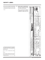
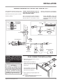
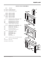
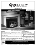
www.regency-fire.com
E21 Gas Insert
Owners &
Installation Manual
MODELS: E21-NG1 Natural Gas E21-LP1 Propane
WARNING:
FOR YOUR SAFETY
If the information in these instructions are not followed exactly, What to do if you smell gas:
a fire or explosion may result causing property damage,
Do not try to light any appliance
personal injury or loss of life.
Do not touch any electrical switch:
do not use any phone in your
FOR YOUR SAFETY
building.
Do not store or use gasoline or other flammable vapors and
Immediately call your gas supplier
liquids in the vicinity of this or any other appliance.
from a neighbour's phone. Follow
the gas supplier's instructions.
Installation and service must be performed by a qualified
If you cannot reach your gas
installer, service agency or the gas supplier.
supplier, call the fire department.
Tested by:
918-354a
Installer: Please complete the details on the back cover
and leave this manual with the homeowner.
Homeowner: Please keep these instructions for future reference.
FPI FIREPLACE PRODUCTS INTERNATIONAL LTD. 6988 Venture St., Delta, BC Canada, V4G 1H4
10/25/05
CONGRATULATIONS!
You are the owner of a state-of-the-art Gas Insert by:
FPI FIREPLACE PRODUCTS INTERNATIONAL LTD.
The Regency Gas Fireplace Series has been designed to provide you with all the warmth and charm
of a fireplace, at the flick of a switch. The models E21-NG1 and E21-LP1 of this series have been
approved by Warnock Hersey for safety. As it also bears our own mark, it promises to provide you with
economy, comfort and security for many trouble free years to follow. Please take a moment now to
acquaint yourself with these instructions and the many features of your Regency Fireplace.
2
Regency E21 Gas Fireplace Insert
TABLE OF CONTENTS
E21 GAS INSERT
Page
Page
SAFETY LABEL
OPERATING INSTRUCTIONS
Safety Label ..................................................................4
Operating Instructions .................................................20
Lighting Procedure ......................................................20
Shutdown Procedure ...................................................20
First Fire ......................................................................20
Copy of Lighting Plate Instructions ..............................21
Automatic Convection Fan Operation .........................22
Normal Operating Sounds of Gas Appliances .............22
INSTALLATION INSTRUCTIONS
Before You Start ............................................................5
General Safety Information ...........................................5
Policy for Factory Built Fireplaces .................................6
Installation Checklist ......................................................6
Minimum Fireplace Clearances .....................................6
Clearances to Combustibles .........................................7
Gas Connection .............................................................8
System Data ..................................................................8
High Elevation ...............................................................8
Wiring Diagram ..............................................................9
Flue Connector Installation ............................................9
Offset Flue Adaptor .....................................................10
Venting ........................................................................10
Combustion & Ventilation Air .......................................10
Gas Pressure Test .......................................................10
Aeration System ..........................................................11
Test for Flue Spillage ...................................................11
Optional Brick Panel ...................................................11
Log Set Installation ......................................................11
Faceplate & Trim .........................................................12
Flush Glass .................................................................13
Flush Louvers ..............................................................13
Bay Front .....................................................................14
Bay Louvers ................................................................14
Conversion Kit from Natural Gas to Propane ..............15
Full Screen Front .........................................................17
Remote Control ...........................................................19
Remote Wall Switch ....................................................19
Wall Thermostat ..........................................................19
Final Check .................................................................20
Regency E21 Gas Fireplace Insert
MAINTENANCE
Maintenance Instructions ............................................22
Log Replacement ........................................................22
Glass Gasket ...............................................................22
Gold-Plated Trim .........................................................22
Door Glass Replacement ............................................23
Removing and Replacing Valve Assembly ..................23
Removing and Replacing the Fan ...............................23
PARTS
Parts List .....................................................................24
WARRANTY
Warranty ......................................................................31
3
For the State of Massachusetts, installation
and repair must be done by a plumber or
gasfitter licensed in the Commonwealth of
Massachusetts.
For the State of Massachusetts, flexible
connectors shall not exceed 36 inches in
length.
4
Model/ E21-NG1
Modele:
NOT FOR USE WITH SOLID FUEL. NE PAS UTILISER AVEC DU COMBUSTIBLE SOLIDE.
Minimum input
Maximum input
Orifice size
Altitude
Manifold pressure low
Manifold pressure high
MADE IN CANADA / FABRIQUE AU CANADA
FPI Fireplace Products International Ltd., Delta, B.C., Canada
E21-LP1
APPAREIL FONCTIONNANT CONCU POUR
Propane
ETRE INSERE DANS UN FOYER
12.0" WC/C.E. (2.99 kPa) Pression d’alimentation minimum
276
Top of unit to
mantle / Au dessus:
B 14"/355mm
Side of unit to wall /
Cote:
A 9"/229mm
918-355a
Minimum Clearances to Combustibles/
Degagement Minimum Des Materiaux
Combustibles:
Serial No./ No
de Serie
For installation into a vented non-combustible fireplace, listed factory built fireplace. This vented gas
fireplace heater is not for use with air filters.
Ne peut etre installe que dans un foyer non
3.8" WC/C.E. (0.95 kPa)
11.0" WC/C.E. (2.74 kPa) Pression tublure d'échappement élevée combustible muni d'un event. Ne pas utiliser de
1.1" WC/C.E. (0.27 kPa)
2.9" WC/C.E. (0.72 kPa) Pression tublure d'échappement basse filtre à air avec ce foyer au gaz à évacuation.
WARNING: This fireplace has been converted
0-2000 ft.
2000 - 4500 ft.
0-4500 ft.
L'altitude
for use with a gas fireplace insert only and
(0 - 610m)
(610 - 1372m)
(0-1372m)
cannot be used for burning wood or solid fuels
unless all original parts have been replaced, and
43 DMS
44 DMS
54 DMS
Grandeur de l’injecteur
the fireplace re-approved by the authority having
23,500 Btu/h 22,000 Btu/h
22,500 Btu/h
Debit calorifique maximum
jurisdiction.ELECTRICAL SUPPLY/ALIMENTATION
ELECTRIQUE:115V60HZ less than/Moins de 2 AMP.
11,750 Btu/h 11,000 Btu/h
11,250 Btu/h
Debit calorifique minimum
E21-NG1
Natural Gas (Naturel Gaz)
Minimum supply pressure 5.0" WC/C.E. (1.25 kPa)
Please note that with the addition
of thermostat control and outside
combustion air supply, this unit is
approved for bedroom installations.
FIREPLACE INSERT:
For the State of Massachusetts, the appliances individual manual shut-off must be a
t-handle type valve.
Note: Regency units are constantly being
improved. Check the label on the unit
and if there is a difference, the label
on the unit is the correct one.
DO NOT REMOVE THIS LABEL/ NE PAS ENLEVER CETTE ÉTIQUETTE
276
This is a copy of the label that accompanies
each Regency Gas Insert. We have printed
a copy of the contents here for your review.
The safety label is located on the front inside
base of the unit visible when the bottom louver
is open.
Listed: VENTED GAS FIREPLACE HEATER
Tested to: ANSI Z21.88b-2003/CSA-2.33b-2003, CGA 2.17-M91
Gas fired appliance for use at high altitude.
Certified for/Certifee pour: CANADA and U.S.A. Report No. 476-1428-00 (DEC. 2000)
Duplicate Serial No.
SAFETY LABEL
E21-LP1
Regency E21 Gas Fireplace Insert
INSTALLATION
IMPORTANT:
SAVE THESE
INSTRUCTIONS
The Regency Gas Fireplace must be installed
in accordance with these instructions. Carefully
read all the instructions in this manual first.
Consult the "authority having jurisdiction" to
determine the need for a permit prior to starting the installation. It is the responsibility of the
installer to ensure this fireplace is installed in
compliance with the manufacturer's instructions
and all applicable codes.
BEFORE YOU START
Safe installation and operation of this appliance requires common sense, however, we
are required by the Canadian Safety Standards
and ANSI Standards to make you aware of the
following:
INSTALLATION AND REPAIR
SHOULD BE DONE BY A
QUALIFIED SERVICE PERSON.
THE APPLIANCE SHOULD
BE INSPECTED BEFORE USE
AND AT LEAST ANNUALLY BY
A PROFESSIONAL SERVICE
PERSON. MORE FREQUENT
CLEANING MAY BE REQUIRED
DUE TO EXCESSIVE LINT FROM
CARPETING, BEDDING MATERIAL,
ETC. IT IS IMPERATIVE THAT
CONTROL COMPARTMENTS,
BURNERS AND CIRCULATING
AIR PASSAGEWAYS OF THE
APPLIANCE BE KEPT CLEAN.
DUE TO HIGH TEMPERATURES,
THE APPLIANCE SHOULD BE
LOCATED OUT OF TRAFFIC AND
AWAY FROM FURNITURE AND
DRAPERIES.
WARNING: FAILURE TO INSTALL
THIS APPLIANCE CORRECTLY
WILL VOID YOUR WARRANTY AND
MAY CAUSE A SERIOUS HOUSE
FIRE.
CHILDREN AND ADULTS SHOULD
BEALERTED TO THE HAZARDS OF
HIGH SURFACE TEMPERATURES,
ESPECIALLY THE FIREPLACE
GLASS, AND SHOULD STAY AWAY
TO AVOID BURNS OR CLOTHING
IGNITION.
Regency E21 Gas Fireplace Insert
YOUNG CHILDREN SHOULD BE
CAREFULLY SUPERVISED WHEN
THEY ARE IN THE SAME ROOM
AS THE APPLIANCE.
CLOTHING OR OTHER
FLAMMABLE MATERIAL SHOULD
NOT BE PLACED ON OR NEAR
THE APPLIANCE.
GENERAL SAFETY
INFORMATION
1) The appliance installation must conform
with local codes or, in the absence of local
codes, with the current Canadian or National
Gas Codes, CAN1-B149 or ANSI Z223.1
Installation Codes.
2) The appliance when installed, must be
electrically grounded in accordance with
local codes, or in the absence of local codes
with the current National Electrical Code,
ANSI/NFPA 70 or CSA C22.1 Canadian
Electrical Code.
3) See general construction and assembly
instructions. The appliance and vent should
be enclosed.
4) This appliance must be connected to the
specified vent and termination cap to the
outside of the building envelope. Never
vent to another room or inside a building.
Make sure that the vent is installed as per
Venting instructions.
5) This appliance may only be installed in a
vented, solid fuel burning masonry, listed
factory built fireplace, or zero clearance kit
part # 530-936.
6) This appliance is Listed for bedroom
installations when used with a Listed Millivolt
Thermostat. Some areas may have further
requirements, check local codes before
installation.
7) This appliance is Listed for Alcove
installations, maintain minimum Alcove
clearances as follows, minimum ceiling
height of 53-1/2", minimum width of 48"
and a maximum depth of 36".
8) This unit is not approved for installation into
a mobile home.
11) To prevent injury, do not allow anyone who
is unfamiliar with the operation to use the
fireplace insert.
12) Wear gloves and safety glasses for protection
while doing required maintenance.
13) Ensure adequate combustion and ventilation
air.
14) Under no circumstances should this
appliance be modified. Parts that have to
be removed for servicing should be replaced
prior to operating this appliance.
15) Installation and any repairs to this appliance
should be done by a qualified service person.
A professional service person should be
called to inspect this appliance annually.
Make it a practice to have all of your gas
appliances checked annually.
16) Do not slam shut or strike the glass door.
17) Under no circumstances should any solid
fuels (wood, paper, cardboard, coal, etc.)
be used in this appliance.
18) The appliance area must be kept clear and
free of combustible materials, (gases and
other flammable vapours and liquids).
19) Do not use this appliance if any part has been
under water. Immediately call a qualified
service technician to inspect the appliance
and to replace any part of the electrical
control system and any gas control which
has been under water.
20) WARNING: Failure to position
the parts in accordance with the
diagrams in this manual or failure to
use only parts specifically approved
with this appliance may result
in property damage or personal
injury.
21) WARNING: Operation of this
appliance when not connected to
a properly installed and maintained
venting system or tampering with
the blocked vent shut-off system
can result in carbon monoxide (CO)
poisoning and possible death.
Emissions from burning wood or gas could
contain chemicals known to the State of
California to cause cancer, birth defects or
other reproductive harm.
9) Inspect the venting system annually for
blockage and any signs of deterioration.
10) Any safety glass removed for servicing
must be replaced prior to operating the
appliance.
5
INSTALLATION
POLICY FOR SOLID
FUEL BURNING &
FACTORY BUILT
FIREPLACES
The Regency E21 may be installed and vented
into any solid fuel fireplace that has been installed
in accordance with the National, Provincial and
local building codes and is constructed of noncombustible materials.
1) Installer must mechanically attach the supplied label to the inside of the firebox of the
fireplace into which the gas fireplace insert
is installed.
"WARNING: This fireplace has been converted
for use with a gas fireplace insert only and
cannot be used for burning wood or solid fuels
unless all original parts have been replaced,
and the fireplace re-approved by the authority
having jurisdiction."
2) Do not cut any sheet-metal parts of the
fireplace, in which the gas fireplace insert
is to be installed.
3) If the factory-built fireplace has no gas access
hole(s) provided, an access hole of 1-1/2"
(37.5mm) or less may be drilled though the
lower sides or bottom of the firebox in a proper
workmanship like manner. This access hole
must be plugged with a non-combustible
insulation after the gas supply line has been
installed.
4) The fireplace flue damper can be fully blocked
open or removed for installation of the gas
fireplace insert.
5) The fireplace and fireplace chimney must
be clean and in good working order and
constructed of non-combustible materials.
6) The chimney cleanouts must fit properly.
7) Refractory (firebricks), glass doors, screen
rails, screen mesh and log grates can be
removed from the fireplace before installing
the gas fireplace insert.
8) Smoke shelves, shields and baffles may be
removed if attached by mechanical fasteners.
If any part is removed it must not weaken
the structural integrity of the factory built.
9) Trim panels or surrounds shall not seal
ventilation openings in the fireplace.
6
INSTALLATION
CHECKLIST
MINIMUM FIREPLACE
CLEARANCES
1) Locate appliance, check Clearances to
Combustibles, page 7.
Diagram shows the minimum fireplace opening
required to be able to install the Regency gas
fireplace insert.
2) Make gas and electrical connections, page
8. Test the pilot. Must be as per diagram,
page 11.
3) Install Flue Connector, page 9.
4) Install vent, page 10.
5) Test Gas pressure, page 10, and check
aeration, page 11.
6) Test for flue spillage, page 11.
7) Install brick panels (optional), page 11.
8) Install log set, page 11.
9) Install Faceplate and Trim, page 12.
10) Install Flush Door Front (Standard), page
13.
11) Install Optional Bay Front and optional Bay
Gold Trim, page 14.
12) Install Louvers (Flush or Bay), pages 13 and
14.
13) Install optional Wall Switch, Remote Control,
or Wall Thermostat, page 19.
14) Final check, page 20.
Before leaving this unit with the customer,
the installer must ensure that the appliance is
firing correctly and operation fully explained to
customer.
This includes:
1) Clocking the appliance to ensure the correct
firing rate (rate noted on label) after burning
appliance for 15 minutes.
2) If required, adjusting the primary air to ensure
that the flame does not carbon. First allow
the unit to burn for 15-20 min. to stabilize.
Note: If you are installing the Molded Faceplate,
the minimum fireplace dimensions are as
follows:
3) Ensure that the appliance is venting
correctly.
Width (at front): 29-1/8" (740mm)
Depth:
15" (381mm)
Height:
18-5/8" (473mm)
CAUTION: Any alteration to the product that
causes sooting or carboning that results
in damage is not the responsibility of the
manufacturer.
Regency E21 Gas Fireplace Insert
INSTALLATION
CLEARANCES TO
COMBUSTIBLES
The minimum clearance from the side of the appliance to a combustible
side wall is 9 inches (229mm). The minimum clearance from the top of
the louver to a combustible mantel is 14 inches (356mm).
(356mm) The minimum
height from the top of the louver to the ceiling is 36 inches (914mm).
(914mm)
See diagram.
Regency E21 Gas Fireplace Insert
Note: A non-combustible mantel may be installed at a lower height
if the framing is made of metal studs covered with a noncombustible board.
7
INSTALLATION
GAS CONNECTION
Only persons licensed to work with gas piping
may make the necessary gas connections to
this appliance.
The gas connection is a 3/8" NPT accessible on
the left side of the unit. The gas line connection
may be made of rigid pipe, copper pipe or an
approved flex connector. (If you are using rigid
pipe, ensure that the valve can be removed
for servicing.) Since some municipalities have
additional local codes it is always best to consult
with your local authorities and the CAN/CGA
B149 installation code.
For minimum and maximum supply pressure
see the System Data table.
1) If the appliance is to be installed into an
existing chimney system, thoroughly clean
the masonry fireplace that has been chosen
for the Regency Gas Fireplace.
2) The appliance is provided with an opening on
the left hand side of the control compartment
for the gas line.
System Data
For altitude: Natural Gas
Propane:
Burner Inlet Orifice Sizes:
Natural Gas Propane
Burner
#43
#54
Max. Input Rating
- Natural Gas
23,500 Btu/h
- Propane
22,500 Btu/h
Min. Input Rating
- Natural Gas +/-5% 11,750 Btu/h
For USA installations follow local codes and/or
the current National Fuel Gas Code, ANSI
Z223.1.
-Propane
+/-5%
11,250 Btu/h
Supply Pressure
When using copper or flex connectors use only
approved fittings. Always provide a union so that
gas lines can be easily disconnected for burner
or fan servicing. Flare nuts for copper lines and
flex connectors are usually considered to meet
this requirement.
Natural Gas
min.
5.0" w.c.
Propane
min.
12.0" w.c.
Manifold Pressure (High)
Natural Gas
3.8"
+/- 0.2" w.c.
Propane
11"
+/- 0.2" w.c.
Circulation Fan: 120 VAC, 60 Hz
Important: Always check for gas leaks
with a soap and water solution or gas
leak detector. Do not use open flame
for leak testing.
Variable Speed: 127 CFM, thermally
activated
NATURAL GAS E21-NG1
For altitude:
2000 ft - 4500 ft.
Burner Inlet Orifice Size:
Note: During any pressure testing of the gas
supply piping system that exceeds test pressures
of 1/2 psig, this appliance and its individual
shut-off valve must be disconnected from the
piping system. If test pressures equal to or less
than 1/2 psig are used then this appliance must
be isolated from the piping system by closing
its individual manual shut-off valve during the
testing.
CAUTION: If the glass is removed for
servicing, it must be replaced prior to
operating the appliance. The glass must
be fixed in the closed position when
operating.
8
0-2000 ft.
0-4500 ft.
44 DMS
Max. Input Rating
22,000 Btu/h
Min. Input Rating
+/-5% 11,000 Btu/h
HIGH ELEVATION
This unit is approved in Canada for altitude
0 to 4500 ft. (CAN/CGA 2.17-M91) with the
orifice supplied.
Regency E21 Gas Fireplace Insert
INSTALLATION
WIRING DIAGRAM FOR THE E21-NG1 AND E21-LP1
codes the current CSA C22.1 (in Canada) or
with the National Electrical Code ANSI/NFPA
70-1987 (in USA).
When connected with 120 volts, the appliance
must be electrically grounded in accordance
with local codes or, in the absence of local
NOTE: This unit is equipped with a heat
sensor thermodisc which will
prevent the blower from operating
until the unit reaches the correct
temperature.
Grounding
Lug Detail
Star washer
Nut
Power cord
ground wire
Star washer
Neutral
L
O
H
PILO
T
I
ON
Red
Red
OFF
OFF ON
Vent Spill
Switch
(Auto Reset)
CAUTION: Label all wires prior
to disconnection when servicing
controls. Wiring errors can
cause improper and dangerous
operation.
WARNING: Electrical Grounding
Instructions
This appliance is equipped with a
three pronged (grounding) plug for
your protection against shock hazard
and should be plugged directly into
a properly grounded three-prong
receptacle. Do not cut or remove the
grounding prong from this plug.
Black
Rotary Speed
Control
Piezo
Ignitor
White
Brown
"S.I.T" Valve
OFF
Black
Fan
Thermodisc
Thermocouple In
ON
Ground
120V AC Live
60 Hz
Pilot
Assembly
Gas
In
Fan
Black
Thermopile
Fan ground
Green
Ground
Electrode
Nut
Gas Pilot
#8 Ground Lug
Lockwasher
Caution: Ensure that the wires do
not touch any hot surfaces and are
away from sharp edges.
Remote
Receiver
(Optional)
(Millivolt)
Thermostat
(Millivolt)
(Optional)
Black
ON
Red
OFF
Burner
Remote Transmitter
(Optional)
Regency
This heater does not require a 120V A.C. supply
for operation. In case of a power failure, the
burner switch and the optional remote control/
thermostat will continue to operate. However,
a 120V A.C. power supply is needed for the
fan/blower operation.
FLUE CONNECTOR INSTALLATION
1) Remove the screw holding the flue connector
plate to the appliance.
2) Slide the plate out and attach to
the flue liner inside the fireplace
to the flue collar with three sheet
metal screws.
3) Place the appliance on the hearth.
Push the appliance into the fireplace and at the same time slide the
plate back onto the appliance.
4) Replace the screw holding the plate just
before completely pushing the appliance into
the fireplace.
Note: Do not operate unit if flue connector is not
fastened in original position.
Regency E21 Gas Fireplace Insert
9
INSTALLATION
OFFSET FLUE
ADAPTOR
A Offset Flue Adaptor Kit, Part #532-920 is
available as an accessory to move the flue
outlet back for easier liner installations in deep
fireplaces.
B-Vent chimneys require a 1" clearance to
combustibles.
A 3" diameter type B-Vent or approved aluminium
flex liner may also be used with a 4" to 3" reducing adapter. Consult venting charts and local
code requirements.
The Regency Insert incorporates its own internal
draft hood, so no additional external draft hood
is required. Check periodically that the vent is
unrestricted and an adequate draft is present
when the unit is in operation.
Before installing the vent system ensure that the
damper plate is locked into the open position
and secure to prevent the damper plate from
falling down and crushing the liner.
VENTING
THE APPLIANCE MUST NOT BE
CONNECTED TO A CHIMNEY FLUE
SERVING A SEPARATE SOLID FUEL
BURNING APPLIANCE.
This appliance is designed to attach to a 4"
diameter type B-Vent or double thickness
approved aluminium flex liner.
The flue collar of the appliance will fit inside
a standard vent and may be fastened directly
to the vent by sheet metal screw or a B-Vent,
single wall vent connector.
The appliance is equipped with a vent safety
shutoff system and a safety control system
designed to protect against improper venting
of combustion products. The appliance will not
function without being connected to a proper
system.
WARNING: Operation of this heater
when not connected to a properly
installed and maintained venting
system or tampering with the vent
shut-off system can result in carbon
monoxide (CO) poisoning and
possible death.
This appliance must not be connected to a
chimney flue serving a separate solid fuel burning appliance.
For best venting performance, we recommend
the following venting rules:
1) Use only certified Type B gas vent or
approved flex liner.
WARNING: This appliance needs fresh air
for safe operation and must be installed
with provisions for adequate combustion
and ventilation air available to the room in
which it is to be operating.
Follow CAN/CGA B149 (in Canada) or ANSI
Z223.1 (in the USA) requirements, and any
local codes or regulations of the enforcing
authority.
Air for combustion is drawn in through the front
of the unit, therefore, the front of the unit must
be kept clear of any obstructions.
GAS PIPE
PRESSURE TESTING
The appliance must be isolated from the gas
supply piping system by closing its individual
manual shut-off valve during any pressure
testing of the gas supply piping system at test
pressures equal to or less than 1/2 psig. (3.45
kPa). Disconnect piping from valve at pressures
over 1/2 psig.
The manifold pressure is controlled by a regulator
built into the gas control, and should be checked
at the pressure test point.
Note: To properly check gas pressure, both
inlet and manifold pressures should
be checked using the valve pressure
ports on the valve.
1) Make sure the valve is in the "OFF"
position.
2) Follow the vent manufacturer's instructions
and clearance requirements.
2) Loosen the "IN" and/or "OUT" pressure
tap(s), turning counterclockwise with a 1/8"
wide flat screwdriver.
3) Observe any local code restrictions, if any,
regarding the installation of gas inserts.
3) Attach manometer to "IN" and/or "OUT"
pressure tap(s) using a 5/16" ID hose.
4) Use as few elbows as possible.
4) Light the pilot and turn the valve to "ON"
position. Read manometer.
5) Keep horizontal lengths as short as possible
and maintain at least an upward slope of
1/4 in. (6.4mm) for every 12 in. (305mm) of
horizontal run.
6) Terminate the vent with a suitable certified
vent cap.
10
COMBUSTION AND
VENTILATION AIR
5) The pressure check should be carried out
with the unit burning and the setting should
be within the limits specified on the safety
label.
6) When finished reading manometer, turn
off the gas valve, disconnect the hose and
tighten the screw (clockwise) with a 1/8"
flat screwdriver. Note: Screw should be
snug, but do not over tighten
Regency E21 Gas Fireplace Insert
INSTALLATION
Valve Description
1) Gas cock knob
2) Manual high/low adjustment
3) Pilot Adjustment
4) Thermocouple Connection
5) Main Operator
6) Outlet Pressure Tap (Manifold Pressure)
7) Inlet Pressure Tap (Supply Pressure)
8) Pilot Outlet
9) Main Gas Outlet
10) Flange Securing Screw Holes
11) Alternative TC Connection Point
12) Thermoelectric Unit
13) Additional Valve Mounting Hole
GAS INSERT AERATION
SYSTEM
The aeration adjustment rod is attached to the
air shutter which is located just above the orifice
bracket. The rod is used to adjust the aeration
on the main burner without having to take the
appliance apart.
The burner aeration is factory set but may need
adjusting due to either the local gas supply, air
supply or altitude.
Natural Gas:
Propane:
1/8" (3.2mm) open
3/16" (4.8mm) open
Note: Any damage due to carboning
resulting from improperly setting
the aeration controls is NOT covered
under warranty.
Note: Aeration Adjustment should only be
performed by an authorized Regency
Installer at the time of installation or
service.
TEST FOR
FLUE SPILLAGE
a scrap piece of sheet metal (or other
noncombustible material) in the upper louver,
this will prevent the natural convection of the
unit from interfering with the test.
Note: The smoke should be drawn into the
louver. If the smoke is still not drawn
in, turn the unit off and check for the
cause of the lack of draft. If necessary,
seek expert advice.
OPTIONAL
BRICK PANEL
1) Unwrap the brick pattern panels from the
protective wrapping.
2) With the glass removed, position the
back panel first (see diagram for correct
positioning), then the two side panels. Slide
the side brick panel into place from the front
of the firebox, there is a tab at the top of the
unit to hold the side panels in place.
3) The brick panels should be tight against
the firebox sides and back. The side panels
should be flush with the glass.
A " spillage" test must be made before
the installed unit is left with the customer.
Follow the procedure below:
1) Close all external doors and windows in
the house.
2) Light the unit and set controls to maximum.
Turn fan to OFF on unit.
3) After five minutes, test that there is a “pull”
on the flue by placing a smoking match,
cigarette or similar device which gives
off smoke, in front of the upper part of
the louver. To ensure a valid test, place
Note: Use caution when sliding side panels
in as they can easily be scratched by
the brick panel tabs.
Regency E21 Gas Fireplace Insert
11
INSTALLATION
LOG SET
INSTALLATION
4) Place the Front Left Log B) 02-67 on the 2
front pins.
Read the instructions below carefully and
refer to the diagrams. If logs are broken
do not use the unit until they are replaced.
Broken logs can interfere with the pilot
operation.
The gas log kit (set# 532-930) contains
the following:
a)
b)
c)
d)
e)
f)
g)
h)
02-66 Rear Log
02-67 Front Left Log
02-68 Middle Left Log
02-70 Middle Right Log
02-69 Front Right Log
Embers
Vermiculite
Rockwool
Note: Install Optional Brick Panels prior to
installing logs.
5) Place the Middle Right Log D) 02-70 into the
cutout on Rear Log A) 02-66 and the bottom
front of Log D)02-70 snugly between Logs
C) 02-68 and Log B)02-67.
9) Place the Front Right Log E) 02-69 onto the
front right pin and the cutout on the bottom
right side of the log snugly against the right
edge of the burner tray.
1) Carefully remove the logs from the box and
unwrap them. The logs are fragile, handle
with care - do not force into position.
D)02-70
A)02-66
C)02-68
B)02-67
E)02-69
The "02" refer numbers (i.e. 02-66) are
molded into the rear of each log.
E)02-69
Cutout
fits over
the right
edge of
the burner
tray.
6) Position the Middle Left Log C) 02-68 onto
the 2 pins as shown below. The left edge
of the log fits into a notch on the Front Left
Log B) 02-67
2) Sprinkle the vermiculite around the firebox
base. Take some of the embers (approx. 1/3
of the bag) and sprinkle over the vermiculite.
NOTE: Keep the gasket on the front edge
of the firebox clear of vermiculite.
Vermiculite &
Embers
3) Place the
Rear Log
A) 02-66
on the 2
pins on the
rear log
support and
carefully
p u s h
down.
12
Vermiculite
& Embers
Vermiculite
& Embers
FACEPLATE & TRIM
INSTALLATION
The front bottom of Log D)02-70 sits snugly
between Logs C) 02-68 and Log B)02-67.
7) Place the embers on the front lip of the
burner as shown below.
8) Place pieces of rockwool on the front lip of
the burner as shown below.
1) Lay the faceplate panels flat, face down on
something soft so they don't scratch.
2) Take the top faceplate and align the holes
in it with the holes in the side panels. Using
the screws provided, attach from the top of
the panel (the holes in the top panel are
slightly larger than the holes in the side
panel to facilitate easier installation). See
diagram 1. Hint: Don't tighten the trim to
the bottom of the faceplate side panels with
the screws provided. See diagram 1.
Regency E21 Gas Fireplace Insert
INSTALLATION
7) Tuck the wires into the faceplate to keep
them away from the insert using the clip
provided. Attach the clip to the rear of the
faceplate to ensure that the wires do not
touch the side of the unit. See diagram 3.
FLUSH GLASS
1) Install the bottom glass trim onto the glass
support.
2) Slide the glass into the bottom glass trim
and secure with the glass clips using the 2
phillips head screws at the top.
3) Slide the top glass trim by sliding under the
two spring clips.
Note: To re-install the glass, reverse the
procedure.
Diagram 1
Hearth Trim Option: Hearth Trim is an option
that can be used to finish off the installation when
the bottom of the fireplace is higher than the
hearth or to raise the fireplace. Lay the faceplate
side panels flat, face down on something soft
so they don't scratch. Attach the Hearth Trim to
the bottom of the faceplate side panels with the
screws provided. See Diagram 2. Now attach
the assembled pieces to the insert body.
Diagram 3
8) The power cord should be run behind the
faceplate panel.
9) Attach the brass trim to the faceplate by
drilling a 1/8" hole through into the faceplate
using the hole in the trim as a guide. Fasten
the trim to the faceplate panels using the
gold plated screws. See diagram 4.
3) Using the connectors provided, join the left
side trim (with the ON/OFF switch) to the
top trim. See diagram 2. Connect the right
side trim to the top trim.
4) Place the trim on the assembled faceplate
panels, aligning the wire connections from
the switches with the notch on the left side
panel.
5) Connect the fan switch wires by taking the
black and red wires with the male ends (in
the grey harness) and connect them with
the wire connectors from the fan speed
control.
Diagram 4
10) Attach the faceplate panels to the insert
body using the 4 remaining black screws.
See diagram 5.
11) Push the logo plate into the two holes in
the bottom left corner of the faceplate. See
diagram 4.
WARNING
The use of substitute glass will
void all product warranties.
Diagram 2
6) Connect the ON/OFF switch wires by taking
the black and red wires with the female
ends and connecting them to the ON/OFF
switch.
Regency E21 Gas Fireplace Insert
Diagram 5
Do not operate the appliance if the
glass panel(s) are removed, cracked
or broken. Replacement of the glass
panel(s) should be done by a qualified
service person.
13
INSTALLATION
FLUSH LOUVERS
1) The Top Louver is held in place by Spring
Clips. Push into place as shown.
OPTIONAL BAY FRONT
BAY LOUVERS
IMPORTANT
Flush glass must stay in place
when bay option is used. The bay
front is a decorative overlay only.
1) Install top louver by sliding the two bracket
clips into the brackets located on top of the
bay door. See below. The fitted louver leaves
a small gap between faceplate bottom and
louver top.
1) Place the bay door onto the 2 pins on the
top of the unit.
2) Install the Spring Hinges on the left and right
side of the bottom of the Firebox using 2
screws per hinge.
2) Position 2 magnets on the back of each trim
piece close to the ends. Place the top and
bottom trim pieces on the bay front.
Diagram 1
3) Install top and bottom louvers.
Note: Top and bottom louvers and brackets
are different. See diagram below.
3) Place the Bottom Louver near the hinge. Flip
hinge over the Bottom Louver and secure
using 3 screws.
Hinge
Location
Bottom Louver
2) Install bottom louver by sliding the two
bracket clips into the brackets located
underneath the bay door and secure with
2 screws into the bracket on the bottom of
the Bay Front as per diagram 1.
NOTE:
14
The top and bottom trim pieces
are different.
Regency E21 Gas Fireplace Insert
INSTALLATION
Conversion Kit from Natural Gas to Propane Model #533-969
THIS CONVERSION MUST BE DONE BY A QUALIFIED GAS FITTER
IF IN DOUBT DO NOT DO THIS CONVERSION !!
1) Turn the unit off and allow it to cool to room temperature.
2) Shut off gass supply
3) Unplug or disconnect power source to stove.
8) Pull off the pilot cap to expose the pilot orifice.
9) Unscrew the pilot orifice with the allen key (provided) and replace
with the LP pilot orifice in the kit.
4) Remove glass front (see manual).
5) Remove logs and brick panels (if installed).
6) Remove the Grate by removing the screws on each side of the
grate.
Remove the 2 screws holding the grate in position.
7) Remove the Burner Tray by removing 1 screw on each side of the
tray, then slide the tray to the left and lift out.
10) Remove burner orifice with 1/2" wrench. Use another wrench to hold
onto the elbow behind the officeReplace with the #54 orifice in the
Kit.
Remove the 2 screws,
push Burner Tray to the left, and lift off.
Burner
Orifice
Regency E21 Gas Fireplace Insert
15
INSTALLATION
11) Remove and discard the 3 pressure regulator mounting screws (A),
pressure regulator tower (B) and diaphragm (C).
12) Insure that the rubber gasket (D) is properly positioned and install
the new HI/LO pressure regulator assembly to the valve using the
new screws (E) supplied with the kit. Tighten screws securely.
16) Attach clear label "This unit has been converted to Propane" near or
on the serial # decal. Attach white label "This valve has been converted
from NG to LPG using SIT conversion Kit Code 0.907.202" onto the
valve.
13) Replace Burner Tray and reverse steps 6) to 1).
14) Adjust the burner aeration setting from 1/8" to 3/16" as required for
the best flame picture.
15) Remove the switch cover from the left side of the body base and pull
the thermodisc out of the bracket under the left side of the firebox
bottom and replace with the Thermodisc supplied with this kit.
Remove the 2 nuts
holding the switch
box in place,
then pull the
thermosdisc out of
the bracket.
17) Replace yellow "Natural Gas" label with red "Propane" label
18) Check for gas leaks.
19) Check inlet and outlet pressures.
20) Check operation of flame control.
21) Check for proper flame appearance and glow on logs.
16
Regency E21 Gas Fireplace Insert
INSTALLATION
FULL SCREEN FRONT
1) Hold the full screen door up against the unit in order to make the
following wire connections.
3) Completely secure full screen door to the unit by securing 4 screws
to the Left and Right Side Trim.
Pull the ON/OFF connector wires thru the box and connect them to
the switch.
Connect the fan switch wires with the wire connectors from the fan
speed control. Place clips over wires and tuck into side trim.
4) Secure the Top Frame by sliding it on the screws at the top of the full
screen door. It is held in place by magnets.
2) Lift the unit up slightly and push down on the corners of the Bottom
Trim Bracket and slide under unit.
Screw
Push in Corners
Bottom Trim
Bracket
Regency E21 Gas Fireplace Insert
Top Frame
17
INSTALLATION
5) Install Spring Hinges to the Left and Right Side of the bottom of the
firebox using 2 screws per hinge.
7) Install the Left and Right Side Screen Doors by placing over top of
the hinges on the faceplate.
Hold the door at a 45 degree angle to avoid scratching the
faceplate.
Hinge
6) Place Bottom Frame near hinge. Flip hinge over Bottom Frame and
secure with 3 screws each.
Hinge Location
Screen Door
Bottom Frame
8) Close screen doors.
18
Regency E21 Gas Fireplace Insert
INSTALLATION
Option 1:
REMOTE CONTROL
Option 2:
WALL SWITCH
Option 3:
WALL THERMOSTAT
Use the Regency Remote Control Kit approved
for this unit. Use of other systems may void
your warranty.
1) Run the wire through the right or left side
inlet opening. Be careful not to damage the
wire.
The remote control kit comes with a hand held
transmitter, a receiver and a wall mounting
plate.
Note: We recommend a maximum of 15'
of wire but if you wish to go with a
longer run, use the Thermostat Wire
Table.
A wall thermostat may be installed if desired,
connect the wires as per the wiring diagram.
Use table below to determine the maximum
wire length.
O
H
THTP TP TH
OFF
PILO
T
3) Install 3 AAA alkaline batteries in transmitter
and 4 AA alkaline batteries in the receiver.
Install the receiver and its cover in the wall.
Switch the remote receiver to "remote"
mode. The remote control is now ready for
operation.
CAUTION
Do not wire millivolt
wall thermostat wires
to 120V wire.
L
CAUTION
Do not wire millivolt
remote control wires
to 120V wire.
CAUTION
Do not wire millivolt
wall switch wire
to 120V wire.
Regency offers an optional programmable
thermostat but any 250-750 millivolt rated nonanticipator type thermostat that is CSA, ULC or
UL approved may be used.
ON
2) Connect the two wires to the gas valve. See
diagram below.
2) Connect the wire to the supplied wall switch
and install into the receptacle box.
I
1) Choose a convenient location on the wall
to install the receiver and the receptacle
box (protection from extreme heat is very
important). Run wires from the fireplace to
that location. Use Thermostat Wire Table.
Note: Preferable if the thermostat is
installed on an interior wall.
To wall switch,
remote control
or thermostat
To thermopile
Thermostat Wire Table
Recommended Maximum Lead Length
(Two-Wire) When Using Wall
Thermostat (CP-2 System)
Wire Size
14 GA.
16 GA.
18 GA.
20 GA.
22 GA.
Regency E21 Gas Fireplace Insert
Max. Length
50 Ft.
32 Ft.
20 Ft.
12 Ft.
9 Ft.
19
OPERATING INSTRUCTIONS
FINAL CHECK
Before leaving this unit with the customer, the
installer must ensure that the appliance is firing
correctly. This includes:
1) Clocking the appliance to ensure the
correct firing rate (rate noted on label) at
15 minutes.
2) If required, adjusting the primary air to ensure
that the flame does not carbon. First allow
the unit to burn for 15 min. to stabilize.
6) Verify log placement. If the pilot cannot be
seen when lighting the unit - the logs or the
embers have been incorrectly positioned.
7) The unit should never be turned off and on
again without a minimum of a 60 second
wait.
8) When lighting the appliance, the inside of
the glass may fog up, this will burn off after
a few minutes of operation.
7) Turn gas control knob counter clockwise to
"ON".
8) Use the rocker switch to operate main
burner.
9) Rotate the variable flame control to adjust
the flame height higher or lower.
10) Close the bottom louver assembly.
SHUTDOWN
PROCEDURE
Gas In
3) Check for proper draft.
1) Use the rocker switch to turn off the main
burner.
2) Open the bottom louver assembly.
Shut Off
Hi-Low
TPTH TP TH
CAUTION
Any alteration to the product that causes
sooting or carboning that results in
damage to the unit is not the responsibility
of the manufacturer and will not be
covered by the warranty.
Gas Out
Pilot Adjust
LIGHTING PROCEDURE
OPERATING
INSTRUCTIONS
Before operating this appliance, proceed through
the following check list.
1) Read and understand these Instructions
before operating this appliance.
2) Check to see that all wiring is correct and
enclosed to prevent possible shock.
3) Check to ensure there are no gas
leaks.
4) Make sure the glass door is in place. Never
operate the appliance with the door glass
removed.
5) Verify that all venting and the cap is
unobstructed.
IMPORTANT: Gas cock knob cannot be
turned from "PILOT" to "OFF" unless it is
partially depressed.
1) Open the bottom louver assembly
2) If the control knob is in the "OFF" position
proceed to Step 5.
3) Push in gas control knob slightly and turn
clockwise to "OFF". Knob cannot be turned
from "PILOT" to "OFF" unless knob is
pushed in slightly. Do not force.
4) Wait five minutes to allow gas, that may
have accumulated in the main burner
compartment, to escape. If you do smell
gas, follow the instructions on the front of
this manual. If you don't smell gas continue
on to the next step.
5) Turn the gas control counter clockwise to
"PILOT".
6) Push in control knob all the way and hold
in. Continually push and release the black
button on spark igniter until pilot lights.
Continue to hold the control knob in for
approximately one minute, then release
the gas control knob. The pilot flame should
continue to burn. If the pilot does not remain
lit, repeat operation allowing a longer period
before releasing gas control knob.
20
3) Push in the gas control knob slightly and
turn clockwise to "OFF". Do not force.
4) Disconnect all electric power and gas
to the appliance if service is to be
performed.
FIRST FIRE
The first fire in your stove is part of the paint
curing process. To ensure that the paint is
properly cured, it is recommended that you
burn your fireplace for at least four (4) hours the
first time you use it with the fan on. When first
operated, the unit will release an odour caused
by the curing of the paint, the burning off of
any oils remaining from manufacturing. Smoke
detectors in the house may go off at this time.
Open a few windows to ventilate the room for
a couple of hours.
The glass panel may require cleaning after the
unit has cooled down.
DO NOT ATTEMPT TO CLEAN THE
GLASS WHILE IT IS HOT.
Do not use abrasive cleaners on
the glass.
Note: When the glass is cold and the
appliance is lit, it may cause
condensation and fog the glass.
This condensation is normal and will
disappear in a few minutes as the
glass heats up.
DO NOT BURN THE APPLIANCE
WITHOUT THE GLASS FRONT IN
PLACE.
Regency E21 Gas Fireplace Insert
OPERATING INSTRUCTIONS
COPY OF LIGHTING PLATE INSTRUCTIONS
FOR YOUR SAFETY READ
BEFORE LIGHTING
This appliance must be installed in accordance with
local codes, if any; if none, follow the National Fuel
Gas Code, ANSI Z223.1/NFPA 54, or Natural Gas and
Propane Installations Codes, CSA B149.1.
Australia: AG601, New Zealand: NZS 5261
WARNING: If you do not follow these instructions exactly, a fire or explosion may result
causing property damage, personal injury or
loss of life. Improper installation, adjustment, alteration, service or maintenance can
cause injury or property damage. Refer to
the owner’s information manual provided
with this appliance. For assistance or additional information consult a qualified installer,
service agency or gas supplier.
A) This appliance has a pilot which must be lighted by
hand. When lighting the pilot, follow these instructions
exactly.
B) BEFORE LIGHTING smell all around the appliance
area for gas. Be sure to smell next to the floor because
some gas is heavier than air and will settle on the floor.
WHAT TO DO IF YOU SMELL GAS
- Do not try to light any appliance
- Do not touch any electric switch, do not use any phone
in your building.
- Immediately call your gas supplier from a neighbours
phone. Follow the gas supplier’s instructions.
- If you cannot reach your gas supplier, call the fire
department.
C) Use only your hand to push in or turn the gas control
knob. Never use tools. If the knob will not push in or turn
by hand, don’t try to repair it, call a qualified Service
Technician. Force or attempted repair may result in a fire
or explosion.
D) Do not use this appliance if any part has been under
water. Immediately call a qualified service technician to
inspect the appliance and to replace any part of the
control system and any gas control which has been
under water.
This appliance needs fresh air for safe operation and
must be installed so there are provisions for adequate
combustion and ventilation air.
CAUTION: Hot while in operation. Do not touch.
Severe Burns may result. Due to high surface
temperatures keep children, clothing and
furniture, gasoline and other liquids having
flammable vapors away. Keep burner and
control compartment clean. See installation
and operating instructions accompanying
appliance.
LIGHTING INSTRUCTIONS
STOP! Read the safety information above on
this label.
1) Push in gas control knob slightly and turn
clockwise to “OFF”. Knob cannot be
turned from “PILOT” to “OFF” unless knob is
pushed in slightly. Do not force.
2) Wait five (5) minutes to clear out any gas.
If you then smell gas STOP! follow “B” in the
safety information above on this label. If you
don’t smell gas, go to the next step.
3) Turn knob on gas control counterclockwise
to“PILOT”
.
4) Push in control knob all the way and hold in.
Continually push and release the black button
on spark igniter until pilot lights. Continue to
hold the control knob in for about 1/2 minute
after the pilot is lit. Release knob and it will pop
back up. Pilot should remain lit. If it goes out,
repeat steps 1) to 4). If knob does not pop up
when released, stop and immediately call your
service technician or gas supplier. If the pilot
will not stay lit after several tries, turn the gas
control knob to “OFF” and call your service
technician or gas supplier.
5) Turn gas control knob counterclock-wise to
“ON”
.
6) Use rocker switch to operate main burner.
TO TURN OFF GAS APPLIANCE
1) Push in the gas control knob slightly and
turn clockwise to “OFF”. Do not force.
2) Turn off all electric power to the appliance
if service is to be performed.
918-048a
DO NOT REMOVE THIS INSTRUCTION PLATE
Regency E21 Gas Fireplace Insert
21
MAINTENANCE
AUTOMATIC
CONVECTION FAN
OPERATION
The fan operates automatically, turn the knob on
the side of the faceplate to adjust to the desired
speed. The fan will turn on as the stove comes
up to operating temperature. After the unit has
been turned off and the unit cooled to below a
useful heat output range the fan will shut off
automatically.
NORMAL OPERATING
SOUNDS OF GAS
APPLIANCES
It is possible that you will hear some sounds
from your gas appliance. This is perfectly normal
due to the fact that there are various gauges
and types of steel used within your appliance.
Listed below are some examples. All are normal
operating sounds and should not be considered
as defects in your appliance.
Blower:
Regency gas appliances use high tech blowers
to push heated air farther into the room. It is not
unusual for the fan to make a "whirring" sound
when ON. This sound will increase or decrease
in volume depending on the speed setting of
your fan speed control.
Burner Tray:
The burner tray is positioned directly under the
burner tube(s) and logs and is made of a different
gauge material from the rest of the firebox and
body. Therefore, the varying thicknesses of steel
will expand and contract at slightly different
rates which can cause "ticking" and "cracking"
sounds. You should also be aware that as there
are temperature changes within the unit these
sounds will likely re-occur. Again, this is normal
for steel fireboxes.
Blower Thermodisc:
When this thermally activated switch turns ON
it will create a small "clicking" sound. This is the
switch contacts closing and is normal.
Pilot Flame:
While the pilot flame is on it can make a very
slight "whisper" sound.
Gas Control Valve:
As the gas control valve turns ON and OFF, a
dull clicking sound may be audible, this is normal
operation of a gas regulator or valve.
Unit Body/Firebox:
Different types and thicknesses of steel will
expand and contract at different rates resulting
in some "cracking" and "ticking" sounds will be
heard throughout the cycling process.
22
MAINTENANCE
INSTRUCTIONS
1) Always turn the gas valve to off before
cleaning. For relighting, refer to lighting
instructions. Keep the burner and control
compartment clean by brushing and
vacuuming at least once a year.
When cleaning the logs, use a clean soft
paint brush as the logs are fragile and easily
damaged.
2) Clean (never when unit is hot) appliance,
door and louvers with a damp cloth. Never
use an abrasive cleaner. The gold louvers
(and optional gold door) may be scratched
if abrasives are used to clean them.
The heater is finished in a heat resistant
paint and should only be refinished with
heat resistant paint (not with wall paint).
Regency uses StoveBrite Paint - Metallic
Black #6309.
3) Make a periodic check of burner for proper
position and condition. Visually check the
flame of the burner periodically, making sure
the flames are steady; not lifting or floating.
If there is a problem, call a qualified service
person.
4) The appliance and venting system must be
inspected before use, and at least annually,
by a qualified field service person, to ensure
that the flow of combustion and ventilation
air is not obstructed.
During the annual service call, the burners
should be removed from the burner tray
and cleaned. Replace the embers but do
not block the pilot.
5) Keep the area near the appliance clear and
free from combustible materials, gasoline
and other flammable vapours and liquids.
6) Each time the appliance is lit, it may cause
condensation and fog the glass. This
condensation and fog is normal and will
disappear in a few minutes as the glass
heats up.
Never operate the appliance without
the glass properly secured in place
or with the door open.
7) Verify proper operation after servicing.
8) Periodically check the pilot flames, see
the diagrams on page 11. If you have
an incorrect flame pattern, contact your
Regency dealer for further instructions.
WARNING: CHILDREN AND ADULTS
SHOULD BE ALERTED TO THE
HAZARDS OF HIGH SURFACE
TEMPERATURE AND SHOULD
STAY AWAY TO AVOID BURNS OR
CLOTHING IGNITION. YOUNG
CHILDREN SHOULD BE CAREFULLY
SUPERVISED WHEN THEYARE IN THE
SAME ROOM AS THE APPLIANCE.
CAUTION: ANY SAFETY SCREEN OR
GUARD REMOVED FOR SERVICING AN
APPLIANCEMUSTBEREPLACEDPRIOR
TO OPERATING THE APPLIANCE.
CLOTHING OR OTHER FLAMMABLE
MATERIAL SHOULD NOT BE PLACED
ON OR NEAR THE APPLIANCE.
LOG REPLACEMENT
The unit should never be used with broken logs.
Turn off the gas valve and allow the unit to cool
before opening door to carefully remove the
logs. The pilot light generates enough heat to
burn someone. If for any reason a log should
need replacement, you must use the proper
replacement log. The position of these logs
must be as shown in the diagram under Log
Installation.
NOTE: Improper positioning of logs may
create carbon build-up and will alter
the unit’s performance which is not
covered under warranty.
GLASS GASKET
If the glass gasket requires replacement use
7/8" flat glass gasket (Part # 936-243) for the
Bay Front and for the Flush Front.
GOLD-PLATED
ACCESSORIES
The 24 carat gold plated finish on the accessories
requires little maintenance, and need only be
cleaned with a damp cloth. DO NOT use abrasive
materials or chemical cleaners, as they may
harm the finish and void the warranty.
Clean any fingerprints off before turning the
unit on. If the top louvers start to discolour,
check the door gasket seal and replace if
necessary.
Regency E21 Gas Fireplace Insert
MAINTENANCE
DOOR GLASS
REPLACEMENT
Your Regency stove is supplied with high
temperature, 5 mm Neoceram ceramic glass that
will withstand the highest heat that your unit will
produce. In the event that you break your glass
by impact, purchase your replacement from an
authorized Regency dealer only, and follow our
step-by-step instructions for replacement.
Bay Glass Removal
1) Remove the door from the unit and place
on a soft surface to prevent scratching.
2) Remove the nuts holding the glass retainers
in place.
3) Remove the glass retainers (sides, top and
bottom).
4) Replace the glass. The glass must have
gasketing around it.
REMOVING VALVE
ASSEMBLY
12) Remove the 2 screws on each side of the
firebox bottom and 4 screws on the rear
wall., and lift out.
1) Disconnect the power.
2) Shut off the gas.
3) Remove top and bottom louvers.
4) Remove top and bottom trim.
5) Remove glass.
6) Remove
panels.
log set & embers, and brick
7) Disconnect the gas line.
8) Remove wires from valve (top and bottom
terminals).
13) Remove valve assembly from stove body
by removing 3 phillips screws.
9) Remove the burner tray by removing the 1
screw on each side, then slide the tray to
the left and lift out.
5) Reverse the previous steps, replace the
retainers and fasten with the nuts but do not
over tighten, as this can break the glass.
14) Remove the valve from the bracket and
replace. Reverse steps to install valve.
6) Replace door on the stove and check the
seal.
Remove 2 screws, then push burner tray to
left and lift out.
10) Remove the 2 screws to the right of the
cutout on the firebox bottom.
REMOVING THE FAN
IMPORTANT
Disconnect power supply
before servicing
1) Disconnect the power.
2) Shut off the gas.
3) Remove top and bottom louvers.
4) Remove top and bottom trim.
5) Remove glass.
11) Remove the switch cover from the left side
of the body base and pull the thermodisc
out of the bracket under the left side of the
firebox bottom.
6) Remove logs, embers, and brick panels.
7) Remove Burner Tray and Firebox bottom
- see steps 9) to 12) in "Removing Valve
Assembly.
8) Remove wires from fan.
Flush Glass Replacement
9) Lift fan off of the two pins.
Replace with new flush front as on page 13.
10) Reverse steps to install fan.
Remove the 2 nuts
holding the switch
box in place,
then pull the
thermosdisc out of
the bracket.
Regency E21 Gas Fireplace Insert
23
PARTS LIST
MAIN ASSEMBLY
Part #
Description
530-518/P
Fan Assembly
8)
10)
12)
13)
17)
910-331/P
910-750
910-752
*
936-238
936-233
W241050
910-233
*
532-516
910-343
*
532-012
Fan Motor (120V)
Power Cord (120V)
Wire Harness (Intermediate)
Firebox Bottom
Soft Fiber Gasket 8mm
3/4" Rope Gasket
Fan AUTO ON/OFF Thermodisc - NG
Fan AUTO ON/OFF Thermodisc - LP
Thermodisc Bracket
Draft Hood Slide Plate
Spill Switch
Spill Switch Bracket
Baffle
21)
23)
532-910
532-912
532-914
*
*
Flush Louver (set)-Black
Flush Louver (set)-Gold/Black
Flush Louver (set)-Steel/Black
Top Flush Louver
Bottom Flush Louver
530-952
Bay Louver (set)-Black
1)
2)
3)
4)
5)
7)
24
Part #
Description
25)
26)
530-954
530-955
*
*
Bay Louver (set)-Gold/Black
Bay Louver (set)-Steel/Black
Top Bay Louver
Bottom Bay Louver
33)
34)
35)
36)
530-945
532-901
532-902
532-903
532-904
*
*
*
400-090
Brick Panel Set - Standard
Brick Panel Set - Standard Brown
Brick Panel Set - Standard Red
Brick Panel Set - Herringbone Brown
Brick Panel Set - Herringbone Red
Brick Panel - Rear
Brick Panel - Left Side
Brick Panel - Right Side
Brick Clips
38)
39)
402-046
530-547/P
Glass Support Trim - Black
Flush Front Glass Assembly
49)
532-920
Offset Flue Adaptor Kit
530-936
918-354
Zero Clearance Kit
E21 Manual
*Not available as a replacement part.
Regency E21 Gas Fireplace Insert
PARTS LIST
BURNER ASSEMBLY & LOG SET
Part #
Description
533-574/P
533-576/P
910-098
910-099
Valve Assembly- Nat. Gas
Valve Assembly - Propane
Valve SIT - Nat. Gas
Valve SIT - Propane
59)
62)
910-190
910-076
910-077
904-162
904-163
402-526
532-530
Piezo Ignitor & Nut
Pilot Assembly - SIT - 3 flame -NG
Pilot Assembly - SIT - 3 flame - Propane
#43 Orifice (NG)
#54 Orifice (LP)
Grate/Diffuse Assembly
Burner Assembly - NG/LP
69)
532-930
Complete Log Set
533-969
Conversion to Propane Kit
52)
53)
56)
*Not available as a replacement part.
Regency E21 Gas Fireplace Insert
25
PARTS LIST
BAY & FLUSH FRONT ASSEMBLY
Part #
Bay Door
530-950
106) 940-312/P
107) 936-243
108) 940-313/P
110) 902-183
402-905
402-906
Complete Bay Front c/w Black Trim
Side Glass
Gasket - Adhesive Backed 7/8"
Center Glass
Bay Brick Panel - Standard
Bay Brick Panel - Standard Brown
Bay BricK Panel - Standard Red
111)
112)
113)
400-153
904-196
400-152
Bay Glass Trim Top-Black
1" Round Ceramic Magnet
Bay Glass Trim Bottom - Black
402-956
402-958
Gold Trim Bay Front
Steel Trim Bay Front
*
*
Glass Retainer - Side - Top & Bottom
Glass Retainer - Center - Top & Bottom
114)
115)
26
Description
Part #
Flush Door
530-547/P
107) 936-243
153) *
154) *
157) *
158) 402-033
159) 532-960
Description
Flush Door Assembly Complete
Gasket - Adhesive Backed 7/8"
Glass Side Trim
Flush Glass
Screw #10-24 x 1/2" Truss Head
Flush Glass Bracket
Bay Front Screen
*Not available as a replacement part.
Regency E21 Gas Fireplace Insert
PARTS LIST
FACEPLATE ASSEMBLY
Part #
91)
92)
93)
Description
910-330
904-569
910-246
Fan Speed Control (120 V)
Fan Speed Control Knob
Burner Switch ON/OFF (2 way)
400-950
320-940
400-926
320-942
400-928
320-944
400-959
320-946
Hearth Trim 1" Standard
Hearth Trim 1" Oversize
Hearth Trim 2" Standard
Hearth Trim 2" Oversize
Hearth Trim 4" Standard
Hearth Trim 4" Oversize
Hearth Trim 6" Standard
Hearth Trim 6" Oversize
532-918
*
*
*
*
*
*
532-950
Faceplate & Trim (Set) - Standard-Contour - Black
Faceplate Standard-Contour- Side Right
Faceplate Standard-Contour-Top
Faceplate Standard-Contour- Side Left
Faceplate Standard-Contour- Trim Right
Faceplate Standard-Contour- Trim Top
Faceplate Standard-Contour- Trim Left
Trim (Set) - Standard - Contour (Brass)
141)
142)
143)
144)
145)
146)
532-919
*
*
*
*
*
*
Faceplate & Trim (Set) - Oversize-Contour - Black
Faceplate Contour- Oversize-Side Right
Faceplate Contour- Oversize-Top
Faceplate Contour- Oversize-Side Left
Trim Contour-Oversize-Side Right
Trim Contour-Oversize-Top
Trim Assy-Contour-Oversize-Side Left
181)
182)
183)
184)
185)
186)
187)
531-933
*
*
*
*
*
*
*
Molded Faceplate & Trim (Set)
Faceplate Molded - Side Right
Faceplate Molded - Top
Faceplate Molded - Side Left
Mounting Bracket - Right
Filler Bracket
Mounting Bracket - Left
Screw - #8 x 3/4" Pan Head
402-918
Faceplate & Trim (Set) - Zero Clearance Kit-Contour
94)
95)
121)
122)
123)
124)
125)
126)
190) *
199) 948-216
Screw - #8 x 1/2" Black Self Tapping
Regency Logo
*Not available as a replacement part.
Regency E21 Gas Fireplace Insert
27
NOTES
___________________________________________________
___________________________________________________
___________________________________________________
___________________________________________________
___________________________________________________
___________________________________________________
___________________________________________________
___________________________________________________
___________________________________________________
___________________________________________________
___________________________________________________
___________________________________________________
___________________________________________________
___________________________________________________
___________________________________________________
___________________________________________________
___________________________________________________
___________________________________________________
___________________________________________________
___________________________________________________
___________________________________________________
___________________________________________________
___________________________________________________
___________________________________________________
28
Regency E21 Gas Fireplace Insert
NOTES
___________________________________________________
___________________________________________________
___________________________________________________
___________________________________________________
___________________________________________________
___________________________________________________
___________________________________________________
___________________________________________________
___________________________________________________
___________________________________________________
___________________________________________________
___________________________________________________
___________________________________________________
___________________________________________________
___________________________________________________
___________________________________________________
___________________________________________________
___________________________________________________
___________________________________________________
___________________________________________________
___________________________________________________
___________________________________________________
___________________________________________________
___________________________________________________
Regency E21 Gas Fireplace Insert
29
NOTES
___________________________________________________
___________________________________________________
___________________________________________________
___________________________________________________
___________________________________________________
___________________________________________________
___________________________________________________
___________________________________________________
___________________________________________________
___________________________________________________
___________________________________________________
___________________________________________________
___________________________________________________
___________________________________________________
___________________________________________________
___________________________________________________
___________________________________________________
___________________________________________________
___________________________________________________
___________________________________________________
___________________________________________________
___________________________________________________
___________________________________________________
___________________________________________________
30
Regency E21 Gas Fireplace Insert
WARRANTY
Regency Fireplace Products are designed with reliability and simplicity in mind. In addition, our internal Quality Assurance Team carefully inspects each unit
thoroughly before it leaves our facility. FPI Fireplace Products International Ltd. is pleased to extend this limited lifetime warranty to the original purchaser of a
Regency Product. This warranty is not transferable.
The Warranty: Limited Lifetime
The combustion chamber, heat exchanger, burner tubes/pans, logs, brick panels and gold plating (against defective manufacture only) are covered under the Limited Lifetime
Warranty for five (5) years for parts and subsidized labour* and parts only thereafter.
Glass is covered for lifetime against thermal breakage only, parts and subsidized labour* for five (5) years and parts only thereafter from date of purchase.
External casting, surrounds and grills are covered against cracks and warps resulting from manufacturer defects, parts and subsidized labour* for three (3) years from the date
of purchase and parts only thereafter.
Special Finishes - One year on brushed nickel and antique copper full screens and doors. You can expect some changes in color as the product "ages" with constant heating
and cooling. FPI warranties the product for any manufacturing defects on the original product. However, the manufacturers warranty does not cover changing colors and marks,
ie. finger prints, etc applied after the purchase of the product. Damage from the use of abrasive cleaners is not covered by warranty.
Electrical and mechanical components such as blowers, switches, wiring, thermodiscs, FPI remote controls, spill switches, thermopiles, thermocouples, pilot assembly components,
and gas valves are covered for one year parts and subsidized labour* from the date of purchase. Blowers and valves replaced under warranty are considered repairs and continue
as if new with appliance. ie. twelve (12) months from original purchase date of appliance with a minimum of three (3) months coverage from date of replacement.
FPI venting components are covered parts and subsidized labour* for three (3) years from date of purchase.
Simpson Dura-Vent venting components (Direct Vent units) are covered by Simpson Dura-Vent Inc. warranty.
Conditions:
Any part or parts of this unit which in our judgement show evidence of such defects will be repaired or replaced at FPI's option, through an accredited distributor or agent provided
that the defective part be returned to the distributor or agent Transportation Prepaid, if requested.
Porcelain/Enamel - Absolute perfection is either guaranteed nor commercially possible. Any chips must be reported and inspected by an authorized dealer within three days of
installation. Reported damage after this time will be subject to rejection.
It is the general practice of FPI to charge for larger, higher priced replacement parts and issue credit once the replaced component has been returned to FPI and evaluated
for manufacturer defect.
The authorized selling dealer is responsible for all in-field service work carried out on your Regency product. FPI will not be liable for results or costs of workmanship from
unauthorized service persons or dealers.
At all times FPI reserves the right to inspect product in the field which is claimed to be defective.
All claims must be submitted to FPI by authorized selling dealers. It is essential that all submitted claims provide all of the necessary information including customer name,
purchase date, serial #, type of unit, problem, and part or parts requested, without this information the warranty will be invalid.
Exclusions:
This limited Lifetime Warranty does not extend to or include paint, door or glass gasketing or trim.
At no time will FPI be liable for any consequential damages which exceed the purchase price of the unit. FPI has no obligation to enhance or modify any unit once manufactured.
ie. as products evolve, field modifications or upgrades will not be performed.
FPI will not be liable for travel costs for service work.
Installation and environmental problems are not the responsibility of the manufacturer and therefore are not covered under the terms of this warranty policy.
Embers, rockwool, gaskets, door handles and paint are not covered under the terms of this warranty policy.
Any unit which shows signs of neglect or misuse is not covered under the terms of this warranty policy.
The warranty will not extend to any part which has been tampered with or altered in any way, or in our judgment has been subject to misuse, improper installation, negligence
or accident, spillage or downdrafts caused by environmental or geographical conditions, inadequate ventilation, excessive offsets, negative air pressure caused by mechanical
systems such as furnaces, fans, clothes dryer, etc.
Freight damage to stoves and replacement parts is not covered by warranty and is subject to a claim against the freight carrier by the dealer.
FPI will not be liable for acts of God, or acts of terrorism, which cause malfunction of the appliance.
Performance problems due to operator error will not be covered by this warranty policy.
Products made or provided by other manufacturers and used in conjunction with the operation of this appliance without prior authorization from Regency, may nullify your
warranty on this product.
Any alteration to the unit which causes sooting or carboning that results in damage to the interior / exterior facia is not the responsibility of FPI.
* Subsidy according to job scale as predetermined by FPI.
Regency E21 Gas Fireplace Insert
31
Regency fireplace products are designed
with reliability and simplicity in mind. In
addition, our internal Quality Assurance
Team carefully inspects each unit
thoroughly before it leaves our door.
Fireplace Products International
Ltd. is pleased to extend this
Limited Lifetime Warranty to the
original purchaser of a Regency
Product.
See the inside back cover for details.
Register your Regency online at
http://www.regency-fire.com
Installer: Please complete the following information
Dealer Name & Address: ______________________________________________
___________________________________________________________________
Installer: ___________________________________________________________
Phone #: ___________________________________________________________
Date Installed: ______________________________________________________
Serial No.: __________________________________________________________
Regency and energy are trademarks of FPI Fireplace Products International Ltd.
© Copyright 2005, FPI Fireplace Products International Ltd. All rights reserved.
Printed in Canada