1
H
•
MODEL
NO
298.586191
O owner's
:_responsibility
• _ maintenance
el operation
shooting L
Publication
96745_0:205
No.
'
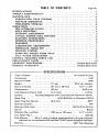
TABLE OF CONTENTS
SPECIFICATIONS
.......
OWNER'S
RESPONSIBILITY
Page
No.
1
2
..................................
MAINTENANCE
..............................
...: .........
LUBRICATION
GEAR
HOUSING
..........................
..
MUFFLER
INSPECTION
...... •
:
..........
PROLONGED
STORAGE
..................................
OPERATIONS
_ .....
......... ............
...........
NEW AUTOMATIC CLUTCH
.....................
.............
BOAT MOUNTING
......................................
....
::
STEERING ADJUSTMENT
...........
: .......................
2-CYCLE ENGINE FUEL MIXTURE
......................
:....
STARTING
PROCEDURES
..............................
:...
STOPPING PROCEDURES
......
., _. •.....
_:....
............
FLOODING
........
: .....
: .......................
CARBURETOR
ADJUSTMENTS
............................
:. .....
PROPELLER SHEAR PIN
IGNITION
SYSTEM
......................................
REMOVING
MOTOR FROM BOAT ..........................
SALT WATER OPERATIONS
..............................
TROUBLE
SHOOTING CHECK LIST
..........................
REPLACEMENT
PARTS .....................................
ORDERING
PROCEDURES
......................
PRODUCT WARRANTY
........................
. . 7
7
7
8
8
8
9
10
Outside BackCover
Outside Back Cover
SPECIFICATION
Type of Engine
: ..................
........
Air Cooled 2.Cycle
Horsepower
.......................................
Maximum RPM .....................................
Weight
..................
Bore and Stroke
Dispiacement
.......
........
(41 turn x 38 mm)
. ............
Fuel Capacity-Engine
Ignition
3.00
7500
(11 kg}
...........
24.3 Lbs. Approx.
....
....
(1.3 liters)
3.05 cu.in.
...............
Flywheel Magneto with Transisterized
Spark Plug ....................
Spark Plug Gap Setting
1.61" x 1.50"
(50 cc) ...............
Tank
1-1/5 qt,
Electronic
(0.6 mm)
.................
025"
Bearings(Engine)....................................
Bearings (Gear Hsg.) .......................
Starter ...............
:.. .......................
Prope[te_" Dia. and P_tch
Lub. (Gear Hsg,)
Fuel Mixture
lubricant
Steering
Ignitor.
NGK BMR.6A or Champion RCJ-8
.......
......
..........................
(18:2 mrn x 130 mm]
Ball
Ball & Oilite Bronze
Recoil
. .
7.17" x 5.12"
. .. ......
SAE 90
, ..
50 to 1 ratio of regular grade gasoline tO 2-cycle outboard
or its equivalent BIA certified TC-W 2-cyc:le Outboard lubricant.
................................
4
4
4
4
4
4
5
5
6
6
6
243" Pivot Steering
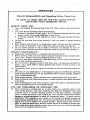
IMPORTANT
Owner's
Responsibility
and Operating
BE SURE TO READ AND
OPERATING
SAFETY
1,
CHECK
Learn
Safety
Check
DO TH_:FOLLOW}N_
YOUR
OUTBOARD
List
_rORE
MOTOR
LIST
and observe
the boating
laws of the U.S.
Coast: Guard.
state, I_aJ
author-
ities
U.S. Coast Guard regulations require=the fo owing:
a. Provide an approved
life-vest, type 1.2 or 3,Personal
Flotation
Device fat each
person in boat, {Encourage pas_ngers to wear them.}
.....
b. if the boat exceeds 16 feet. also carry a type 4. throwable
_iers0'nal Flotation
Device,
2.
3.
Do not
material.
4.
When
,: ,:
5:
fill
fuel
|oading
tank
boat
with
motor
distribule
running
or
near any
the load evenly,
keep
flame
or lighted:smoking
the load
loW; don't:
overload;
don't stand in a u_r_altboat, Take weather and water conditions
into account.
Do not permit
persons to ride on:p_irts of the boat not designed for such use.
Standing. bow riding and seat back Or gunwale riding can be especially dangerous,
OWNER'S
6,
RESPONSIBILITY
Read owner's
manual
before
running
yoUTinew
outboard
motor
.....
L 7.
Before starting, make sure your motor is _curety
mounted
to boat transom with a
safety chain. Tighten clamp st_Jd handlessecurely
by hand.
8. = Be sure tO have pliers, screwdriver,
spare =park plugs, wrench, shear Pins and caller
pins in boat whenever leaving shore,
:
9.
Be sure to have an adequate supply 0f fuel (carry only in an approved container]
on
board.
Use a good grade of regular gasoline with proper mixture,
as Cited in the
Specifications.
Occasionally
check to be sure clamp stud handtes on transom
mounting bracket are
tight,
IN CASE OF AN EMERGENCY.
THE ENGINE
CAN BE STOPPED
8Y DEPRES.
10,
11.
SING THE STOP BUTTON
(IF SO EQUIPPED)
OR PLACING
CHOK E 'KNOB3N_
FULL CHOKE
POSITION.
12. = Keep an alert:lookouL
Serious accidents have resulted from failure to use eyes.
13.
Keep firefighting
and lifesaving equipment
at all times, :
Good housekeeping
is eve6 m0te important
14.
ishes the probability
TIPS
15.
of fi_'e and tripping
FOR TRAILERING
When
launching
in good condition
afloat
b0al
than ashore.
accessible
Cleanliness
dimin.
hazards,
OR AUXILIARY
or loading
and readily
on a trailer,
USE
place
y0ur
Outboard
motor
in the
......
tilted storage position,
Also when trailering your boat and outboard
motor,
keep
outboard
motor
in upright
(vertical)
position
on the boat transom,
Outboard
motors transported
across rough roads tn the "tilt"
pbsitionc0uldcau_
transom
cfamageotmountinQbracket$
to break, oll_ losing your motor,
if motor must _>e
;letec! in
shOrt length of 2 x 4 should :be placed between the
lag, The motor leg should :then be firmly tied down
tO p_=ventany poss_b_
d_ma_.' :sire"orp",Coutio"sshouiJ_e
?
:....
"L:iaken:if:gsii'_g
L,ihe mot0t
aS an auxiliary
When_-using mO't_r al anauxiliary
power
position motor bracket
is reCommended.
gower
source
for a sailboat
or power
r_ource; the use of an auxiliary
boaL
adjustable
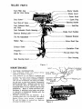
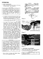
MAJOR PARTS
Starlet Handle
-Choke Lever
Power Head
Spark Plug
Sl0p Bull0n .....
FuelShuFoUValve
Sleeting Handle
Fuel SedimenlB0wl
and Filter
Twist:
Grip
t
Dual AulomalicClulch Housing
_
ReverseDriving LOCkL _
:
-
ClampStud Handles
/
TransomBracket
Tilt Pin Adjuslmenl-
Drive Shall Pipe
MulflerPipe.... _.._
Exhausl0ulleI
Cavilali0n Plale
PropeUerFill and Drain Piu{]
CotlerPin
.Gear Housing
Figure" I
"
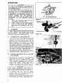
BOLT-----,.
MAINTENANCE
zfj -_- \
/
"
_.' " _,../.GEAR
IIOUSINC:
\, _.... _)._" .,_l
COVEt.
1. FEATURE;INFORMATION
., This
oulboa_(] molt)(
tt'LllUrt)$ ;.,IS
Showr)
1)
YOUr
se|uctlOfl
has,"si_cCl;_i
(..i,)514j=_
OI
OUr
D.A,.,.Log/- >I)
|
It) FIUU(U
_t;_rinu
PEoduc($
will
p_ovidu you witll many hou($ of enioyable
boalmg.
To assure your complete satisfaCtion on the _nveslment
you have just made,
we ask you to read this manual
thoroughly
"before going aflooL
:Acquaint yourself with
the parlicular
areas orf OperalJon on you(
ouIboard m0lbr as y0u re_=dthe s|ep_by;slep
pr0cedutes.
Keep inmind
(ormance
is achieved onty
or opera(or is complelely
CIHIIei"
wh_l_l
PIN_/_,.
P RO PE LL ER :
SHAFT----"
Figure 2
maximum
per.
when Zhe owner
familiar with the
operating instructions.
Periodic
survlcing will be required.
rucorrtm!_lilJ_d
lii;)ll
y(IU COrI._UII your
Service
COTTER
[_rv|_ff
We w(l| be happy (o extend
_lld a;sut!)PrONIDI 5t.'fviCu.
|[
I!
I$
_alr$
n(]cessa('_,
our
(acililies
Figure
3
....
_/'_Y
= "-_3
_i
PROPELLR
MAINTENANCE
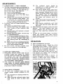
2.
LUBRICATION--GEAR
a.
The Gear Housing has been pre.lubricated
at
the factory; however, the grease level should
HOUSING
be checked as follows
using SAE 90 outboard mo_ur grease° ISee Figure 2).
(I)
Prior to initial operation.
{2)
After firstfour
(4) hoursof use.
(31 Recheck
after every fifty
(50) hours
{3}
The
(4]
mounted
on a stand vertically
power head up for storage.
Pull starter handle slowly until
ance
sure.
b.
C.
: Center before the new season
' _-_.repair work required.
:; _
replace parts and refill geai" housing
using filling procedure
above.
5.
NEW
AUTOMATIC
a.
New
automatic
best results,
lubricate
propeller
shaft
lithium grease every 30 to 60days.
MUFFLER
Periodically
remove
muffler
cover
screwing
screws
and
in._koect f0r
INSPECTION
for any semice
should
carbon
be
to
i:i?':
sudace of the engine components
ping carbon inside of crankcase.
PROLONGED
store
r
STORAGE
your
outboard
motor
for
pro.
longed
storage,
prepare
outboard
as folIows:
(1]
See paragraph on stopping procedures.
{Ref. lOJ
(2)
When removing outboard
motet
from
boat.
unit.
allow
all
water
to
drain
from
a dual
to
a complete
stop
while
the
overheating
When aniline
starts,
motor
ts neutral.
throttle
increases,
sub clutch engages.
::'. approx.
6 MPH.
main
clutch
engages
powei:
_%1
: "''
and drop.
come
':and
prevents
the engine from
and stalling at slow speed._.
inlet andoutlet.
the combustion
Excessive carb0_-
exercised
While €leaning,
prevent
_t-atcbe$
t0:the"
Based on
.engine
continues
operating
efficiently.
1t
eliminates
the need to shift gears by hand
13y:.un.
Ca_:bo:n
will prevei_t ` drawing
the maximum
out Of the engine. (See Figure 3},
CLUTCH
clutch.
centrifugal
clutch design, it allows the out.
board prop to turn at very slow speeds or
_
build.up
inside the muffler
the ; exhaust
port
and
chamber of the cylinder.
To
fresh
coat-
When ub.canthascompletetyarain
OPERATION
.
a.
4.
Housing.
Wipe exterior
completely
with
water Cloth and then apply light
ing of oil,
To achieve complete drainage of fubd.
cant. remove cotter pin0Propelier
andi::
sheep pin from
proPeller:shafto,
ai=6. :.
gear housing covet
b'f unscrewing
2
bolts.
3.
.a.
close both
ports
for
as oullined
of Gear
(5)
Care
away
from
revers.
compression
gear'housing
Replace p!ug and Washer.
is t ightehed _curely.
For
with
plug
resist.
When slatting a new season, always use fresh
gasoline.
Last year's gasoline may
have
varnish
deposits
that will plug the carburetor lels. thus recluiring a complete
over.
haul.
TO plan for the coming season, we recommend
you
contact
your
Sears
Service
even
b.
storage.
Drain and fill
under Lubrication
fRet. 21
[6)
be
with
is felt due to compression
pres.
then stoP. Reteas;e starter tension
(4}
(6)
c.
(5)
insert
nozzle of gear lubricant
tube
into hole.
Squeeze tube until lubricant
is forced
out around tube.
Be_ure
should
pressure.
This positlon'will
the
intake
and
exhaust
runmng time.
Replace with new lubricant at the end
at your outboard
motor season.
This
i_ important,
as it removes any water
from
the gear housing and prevents
possible corrosion to internal
parts.
To Check. Drain or Fill gear housing, follow
these steps:
(I)
Position outboard motor upright.
(2)
Remove drain plug and washer, then
(3)
motor
SlOWly tO prevent
engine
ing
rotation
due
to
(4)
b.
outboard
_
......
provide
direct drive for cruising.
As
AI
to
OPERATION
6. BOAT
,J= Mount
MOUNTING
the motor
transom
(sternl.
on the center
at the bool
{See Figure4).
CAUTION
Hand
tighten
transom
bracket
and clamp
stud handles simultaneously.
0o not use awrench Or any other device that would
cause damage to brackets.
Occasionally
check
to be sure lamp stud handles on
lransom
mounting
|See Figure 5),
l).
TO obtain
uutboard,
lications
Transom
bracket
are
the best performance
IIom ybur
the |oItowing
boat ttaf_som s_)ectare recommended:
(See Figure 4).
Angle (See View 3):
...........
Transom
tight.
Figure
4 ):
L'J_x-.
_ _:- _ €,
20.7
itii:hes
,."-.L...
is easily
Pin and
:_l_l_i_ _,_: _
"
changing
the TiIt Lock Bracket
Pin in the
llve
(5) diHerent
angle
position
holes
rotated
o_ either
Transom
Mounting
side of the
Brackets.
,I
right or lelt
Each angle
TRANSOM
BRACKET
position
elevates
five (5) degrees.
Try
center hole position
first.
(,See Figute 6).
=-"
To find the correct angle position, make a
test run at full
throttle
with y0ur usual
iOo'_ng
4
12 to 15 degrees
Heigh t (See View
..............
_:. The angle
o! the motor
column
_diusted
by removing
the Hitch
d.
V=ew
4
in the boat,
Always
stop motor
CLAMP
to _
change the Tilt Lock Bracket Pin, The car."
rect angle
posit_on
will
have your
boat:.'_
traveling with the bow slighdy
higher than.
STUD
HANDLES
'
Figure 5
....
{he stern,
but should
not porpolse
(bow:
!i
rises and falls rapidly
and continuously).
Be-"
sure Tilt Lock Bracket Pin is always Pushed
completely
ing Brackets
through
both
Transom
Mount'.,
and H_tch Pin is secured.
_WARNING
column
is tilted
If the motor
too
far out,
ward,
the boat is likely
to porpoise or
cavitate
at full
throttle,
which can be
dangerous
because a cross wind or a wave
could suddenly
deflect
the boat into' a
dangerous'
tUrn_
Also,
if
the motor
column iS_tilted t0o far inward, the bow
of the boat will
dig in, which.can
be
dangerous
when: Crossing a wake or in
cough Water.
DO': not run :motor it1' the
storage position.
Figure 4),.
!
(See
VIEW'
.1 and
..,.r:-u'e6
j
T'g
motor
Chain not
I
to
inclu'ded
boat
with
with motor.
Safety
ten steering
tension
bolt
us ng a spanner
:
2,
_
for desiied
|
,'_ Secure
......
Chain.
i
steering effort,(see
CAUTION
There
is a posslbil_ty
backed out too-fat,
of
Figure6),
losing
bolt
:
if
'1
OPERATIOX
8.
2-CYCLE
ENGINE
FUEL
Use agood
grade of regular
in9 table below,)
Always
use BIA
MIXTURE
gasoline.
CAUTION
certified
TC-W
(See mix- _
oil in the
50:1 ratio.
Failure to d0to may result ih
excessive
spark
plug
fouling,
piston
scoring, or bearing failure.
Do not under
any circumstances,
use muttigr_Kle , such 8s
IOW.30, or other automobile
oils.
If BIA certified
Oil is not evaifebie, use
an $AE 30or 40 2-cycle or oiJtboard oil.
We reserve the right to refute
)arts
which
are damaged
improper fuels or lubricants;
Figure 7
warren W on
when using
:WARNING
Gasoline is highly flammable.
Always mix
in wail ventilated
area,
Do not fil! tank
with motor
running,
nor near any flame
or while smoking.
Be surevent
screws
_
and filler
caps on tanks are finger t_ght ened when
transporting
gasoline _ini_the
trunk of
your
automobile
to prevent
explosion,
Figure 7A
U.S. Measure
" Regular
Gasoline
Amount
of oil
to be added
In Gallons
FUEL
!_iMIXING
1
3
5
:6 ':':
,
:
TABLE
;
Reg61ar,
Gasoline
tn Liters
,
•
1
5
_'
!_/
:i
_9_
a,
In Oz
0.16
0.48
0.80
0.96:/_15.4
2.6
_ 7;7
12.8
MattlciMeaSura
MIXTURE
,
In Pints
_
10
20
.......
!:
;;i Am0untof0il
to bi_ added:
!_ ....H,...,HInLlterlt
i
,
,
•
_
i Fibre S
0,20
0.40
e.
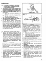
STARTING
PROCEDURE
(See Fig.7
Open air vent screw located on fuel
b,
cap by turning counterclockwlte,
Open fuel shut-off valve,
C,
d.
Open throttle
grip tO half throttle.
Move, choke lever to "On'* positiOn.
"
J
0.02
• 0.10
Pull starter handle slowly until you feel
starter
engage,
Then
pull with rapid
motion
and allow the starter cord tO
retract
& 7A)
filler
f,
After
(See Figure 8),
choke
lever to
"Off"
warming up the engine.
g.
Let
engine
idle
minutes before
"Fast"
position.
WARNING
move with a sudden burst o! speed, Make
sure you ere well sealed so as not to lose
When
starting
outboard,
the boat will
your balance with a last start,
slowly.
engine has started,
10.
STOPPING
To
stop engine,
position
for
moving
gradualiYm0ve
position
while
approximately
throttle
grip
3
to
PROCEDURE
move
throttle
grip
and press stop button.|See
to "Stow"
Figure_TA)
6
OPERATION
L WARN|NG
_
• In case of an Emergency, the engine can
be stopped by moving
the Choke Lever to
FUll Choke Position.
If the motor will not be opelatedif0r_-_
period of time; if it is to be removed from
the boat, or if it is to be tilted:up,
recommend
the
following
praCiice
prevent
spi!lage
from
the
we
:to
carburetor
throat
and bowl .and
to prevent
gum
formations
in
the
carburetor
during
storage;
t.
Close
luel
shut-off
valve
end air
2.
11.
Screw
Figure 9
vent screw at fuel fi!ler cap.
Allow motor
to run at idling speed
until
it stops of it= own
accord,
indicating
the
carburetor
I_as run
dry.
PROPELLER
FLOODING
To c!ear engine of excess fuel, move choke lever
to "Off"
position
and throttle
grip _ to hal!
throttle
position,
Pull_ recoil starter
handle
until enginestarts
and continues to run.
COTTER
Figure
PIN
!0
12. CARBURETOR ADJUSTMENTS
._ Your me=or has a _dle adiust,ng screw and
the idle spet:d has t)_rt
SHE_
_)rese! _t Ih_ #Qctory.
i
However,
you may need to adjust tt?e idle
speed using idle Adjusting
Screw.
Turn that
Screw
clockwise
to increase motor
speedand counter clockwise
to decrease
it. The-
i
•
idle speed adjustment
must be'done
with _.
zhrottie
grip at lull closed position and the
idle speed should be as low as possible whil_
the engine runs steady.
(See Figure 9)
Periodically
check filter fordirt
by, unscrew-,
ing Sediment Bowl
(See Figure 12}
b,
13.
o.
PROPELLER
PIN HOLDER
SHEAR
PIN &
°
Figure 1 I
.:
COTTER
The Shear Pin is used !or the purpose of
protecting
the Drive
Train and Gears.
The
Shear Pin will not prevent
the propeller
from becoming
damaged when striking an
under
water
object.
When shear pin is
broken,
however,
the engine
will continue
to run, ,
the propeller will not be rotating,
Stop
engine immediately
pin to avoid possiblerdama9
CAUTION
b.
To
replace
_emove
collar
she_r
pin,
shut
pin
with
pliers
propeller, (SeeF=gures
c.
after shearing
e to the engine.
10&
otf
_.
!'jgure
,,
1z
}
T
motor,
and slip
off
11].
Replace with new shear pin located in shear
pin and cotter pin holder,
(See Figure 12),
:.
OPERATION
14.
FLYWHEEL
SYSTEM
MAGNETO
WITH
ELECTRONIC
a.
IGNITOR
The magneto
following
sisterized
b.
ignition
system consists of the
component
parts! Flywheel, TranElectronic Ignitor and ignition Coil.
Inmect
the following
herd to start:
_-{1)
(2)
if
engine
fails or is
Spark plug as often as necef4ary.
Be
sure t_oark plug gap setting is .025 "°
(O,6mm).
Gasoline
fuel supply and fuel-shut.
off valve should be open.
Figure
(3)
Carburetor being starved of fuel.
The correct =park plug for this motor
is
NGK 8MR-6A
or Campion RCJ-8.
To
test ignition
system,
remove
mark
plug and place against bare mot on metal
part of motor
away from cylinder
==park
plug hose and then pull starter cord severaltimes.
If a sPark bridges the plug gao. the
magneto
is in good
ooereting
condition,
The high tension lead wire must be con.
nected to the plug for this check. If there
is no sPark, have the ignition
checked it
your Sears Service Center.
c.
d.
15.
a.
IGNITION
TRANSISTERIZED
REMOVING
Always
shroud,
MOTOR
tilt motor
DO NOT
FROM
Figure 14
'
BOAT
Storage:
f.
Close fuel shut-off
by lifting
On rear of
PUSH DOWN
ON THE
ell water
the
16.
To
for
desired
from
effort.
posslble
the
engine
(See
-
is: air ¢oolecl,
J
€._
blOCkDo
notandtouch.UpPer
portion
of the
column.
WATER
J
I
has run dry;
OPERATION
=the life
finishes,
of all exposed
follow
motor
out
lower
un!t
the
d.
Never
leave
the
steps
Of thewater
when not in use.
it iLs I _ b.
to burn your hands on the engine
SALT
materia!ly'increase
parts and decorative
indicated below.
Always
tilt ybur
WARNING
Although
valve and air vent
screw at fuel filler cap,
Allow
motor
to ru n at idling mead
until ff stops Of its own accord, indl.
caring the carburetor
exhaust pipe. When you find it difficult
to
hold the motor
uptight,
tighten the Center
Bolt increasingly
Figurel3).
'
to drain
2.
r
tO allow
WARNING
If the motor
wil.I not be operated
for a
period of
time, if it is tO be removed
from the boat. or if it i€ to be tilted up.
we recommend
the following
practice
to
prevent
millage
from
the
carburetor
throat
and bowl
and to prevent
g_Jm
formations
in the
carburetor
during
STEERING
HANDLE,
When removing the
motor
from the boat, raise the outboard
in
upward
direction
until the propeller
clears
the transom.
::Hold the motor upright long
enough
13
:
in
salt' water
overnight.
•
Wipe e'xteri0r
comp|etely
with fresh water
cloth and then apply light c0ating Of gill
Lubricate
prope_ler shaft occasionally
with
a _ waterproof_Wpe
of lubr cant
{Lithium
It may be necessary to rotate the motor
to
: Grease) , thu s enabling
the propeller
to be
one side before tilting the motor
on the
removed easily.
transom to remove leg from the water when
e_ It is good practice when
operating
insalt
installed on boats with thick transoms.
:
_ 'water. to inspect
your motor
daily and to
C,-Always
carry
outboard
with
the engine': ....
apply
a light coating-of
grease to any
b.
.
d.
above
the lower unit to prevent moisture
from
entering
the
engine
through
the ....
exhaust ports,
f.
part or area that shows
rosion or rust.
Always
remOve
motor
Steering handle serves as carrying
shown in Figure I4,
tically, allOwing water to drain
before tilting the motor.
handle
as
evidence
from
of
boat
cot'
yar-
from column
......
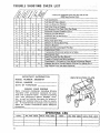
TFIOUBLESHOOTING CHECK LIST
*Take
-.
you_
outboard
2000
motor
into
=_ny one of over
Sears Sq=viee Units.
"l'a=t k Empty
X
X
x
X
X
Fuel
Line Kinked
X
Fuel
Filler
X
X
X
Vent
Screw
X
×
X
Carbufet0=
×
x
Incorrecl
x
F-_.... Z'"
×
X
X
X
X
X
x --'_---_'-X
X
X
× I
X
"
X
X
X
X
.
X
'
•X
.
X
Flooded
X
Defective
agent
.....
-
.
Plug
Transi_;terlzed
Electronic
X
Weak
Ignition
Coil'
Spark
Plug
_ _.
Pug Gap
.
"......
,
"
"
:
Ignitor
oU! of order
-
=
•
Not Seeuzed
Lead Wire
Grounded
Insulation
"
at Loose Wiring
in Electrical
System.
ero_.e, gound.by
_o,e!.g%pbi_c,=
CF=_h__!,0
Line[ Weeds,ElcJ
High Tenllon
"
,
: "
Lead Wire
or Cracked
Spark
Lead-Sail
Waler
Build
"
......
Up
IDENTIFICATION
PLATE
NUMBER
OF
PURCHASE
insurance
Insurance
ble,
.
298.586191
INSURE
damag
Cap Closed
0_ Di;.'ty
INFORMATION
NUMBER:
Many
etc._
Fihe_
Spark
of Timel,
" Disconnected
....
'
Plug
Engine'Ou!
.
DATE
yOUr
Spark
or Fouled
X
Frayed
"
i ............
Mixlure
Not Jump
l
IMPORTANT
boat
:uu,,_
"
Clogged
SPa_k Deal
"
I
SERIAL
. ....
Out o( /_liu_tmenl
Type
x, .
MODEL
Fuel Tank
Fuel-Oil
Wrong
"
s
I
X
on
Engine
I
J
o( Pinched
:-
or Clogged
.... I DeI..,.e.o.°e,O,
....
X
_X
-: .......
Closed
Pass_get
X
X
X
Dirty
Carbu_'elor
r
X
L--__
:
Valve
x
_'i-T-
X
t
Shut,OH
X
Ix
I
Fuel
offer
and
YOUR
protection
outboard
Own
equlpmenl
well
as
e
and
personal
I! would
Allitale
your
covering
damage,
insurance
injury
for
Insurance
against
liability
be wise
further
including
contracts
engine.
as
for
ENGINE
companies
Iheh,
for
property
to
others
to €ontact
your
insurance
abOut
adequate
intorn_alion
is availa-
protection.
."
NO.
......
i............
9
:
HRS,
USED
OPERATING LOG
G_LS,
FUEL
USED
DATE
NO.
HRS.
USEO:
GAtS
FUEL
USED
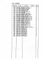
REPLACEMENT ,PARTS
FOR
MODEL No.298.586191
I0
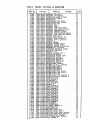
FIG'1
ENGINE
32
75
74
31
B5
86
FIGol
ENGINE
REF.No.
PARTS
P.P,No.
o_e+_o2ol.zou:YLIHD[I
SHIOHD
;sT.o4ooo+goo;PALE PLUG CAP
NAME
ASS'Y
018-00540-200
002-10200-803
017-10200-202
040-10100+ZOO
041-10|00-201
03_-02000-20!
031-10100-210
Q_t-_OIQO-200
048-I0242-800
SPAI[
PLU_-BHESA
_YLIEOEE
COEP,
•
:+[IMDEI
Gks£ET
'
p:ISTON
||KG++
......
PI$TOH+:_II_G
_ISTOXPIX
CI|CLIP
PISTOH_+
,'
PISTON
tll
1¢I35"
C[ANI+$HAFrT_OMP.
088-02000-E00
ggg-O1820.300
999-6_|73.000
ggg_82101"004
HOOD+IUPF
£EY 3Xi+X$.
ALL BEAEIgG
10203
IL SEAL
17301
._
1Sg-21401"871
07|'02007_210
QT}-O200T*220,
07t-i02007+230
071_02007_2(0
IGMITOI
COMP.
TT|+IE
!
_IAMK SHAPT SHIH
O.lO
_|&_
SHA_]
SHIM O+Z5
Ct-A_I
SHAFT
SHI_
0,20
+
CIA,I"$HAFT
SBIH 0.30
BALL HEALING
18202
I_ SEAL
|$30,7
:iA_I
CASE GA$1ET
_gANE CASE ASS'Y
IOHITIOH
COlLCONP.
+OIO+_LAmP
CO_P.
XAGMETO+_6TO_
COXP+
FAH CASE
FLYVH£EL
HASIJEI
KUT I0
{L+H.
TtIEEAO)
gg9+01620*200
ggg+_'iS3-000
090+:10200,20Z
072-10242-t10
161-20751-801
lg4*OSOtS*800
IS$+21717"801
112.:10242-200
085_02501-200
ggl-OOlO0-O01
198+11100-200
250-01048+200
ggO-ll050-10l
ggZ-01050-041
g00-11000*302
902-10O80-042
990-15040.10Z
ggo*l1040-182
992"!0040"042
OgO+11000"Z52
992+100G0_042
Qg2"10080-042
990-_10a0-|82
g92-010S0-0_1
990"11050"102
gQ2-t0040-042
O'ly
I
2
I
I
I
:
I
I
_OIO'CLAMP
L
SPAI£
PLUG _UBBEB
$C_EV
5110
VASXEt
5
S_XEV
8X30
S.tASIIEI
8
$+IEH
4XIO
SCX[V4XI+
S.VASHE_
4
$CREV _X25
S.¥ASEEI
S.:VASEEE
$CXEV
5X|&
HASHER S
S_IEV
5XI0
_.VASKE!
4
+
COVER
V
l
l
B
t
IG.2
TANK,
CLUTCH
& MUFFLER
102
fIG,3
1oo
43
5o
_5
56
55
3O
34
P_._._
-41
:
i
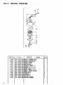
FIG.2
TANK,
CLUTCH
/://
¸¸7¸::¸:
•
& MUFFLER
PARTS
NAME
TANK CAP ASS+Y
TAXi
CAP GASIET.
ENGINE
COVER (SEALS)
CUSHION
HUiBEI
COLLAI
STANTEI
PAUL EASE
STAZTEI
PAVL SPNIHG
STAITEl
PAUL
STEPBOLT
FUEL TAXI
FUEL TAME BAND COMP.
FUEL TAN[
DBACXET
CONP+
FUEL TAXI
BEACKET
9
TA#I
SHPPOIT
IUOBE!
FUEL TAXI
CUSHION
_UBBE_
PUlL
TAXI
CUSHION
lUeBEX
PET+COCK
AS$*Y
PET-COCI
FIXING
NUT
FUEL PIPE
SXBXIID
FUEL PiPE
4,SXBXi40
CLIP
D
rIM
HOLDEI
STOP
BUTTON COVEI
STOP BUTTO_
COHP.
STOP lgtTOX
FIXIXO
NOt
SPECIAL
S,MASHEI
IHLET
MAAIFOLD
GASIET
INLET
MANIFOLD
CLIP
7,5
All
CLEA#EI
ASS'¥
CLUTCH FLANGE
CLUTCS
SPIING
COMP,
CLUTCH
VASItEB
A
CLUTC_
AIM COHP,
CLUTCff
UASHEK I
CLUTCX
STEP BOLT
CLUTCB
SPIING
FLYV_EEL
VASHEE
XUT IO
(L.U.
TIINEAD)
HHFFLEB
GASKET
MUFFLEI
BOOT A
HUFFLEN
GAS[ET
XUVFbEI
BoDY i
MUFPLEI
PIPE
GASEET
MUFPLEI
PIPE
STAY A
MUFFLE!
PIPE
KUFFLEI
PIPE
BIACIET
MUFFLER +PIPE
BIACtET
SCIEV
5X45
S.VASXEI
S
VASHE|
5
$CIEV
6X12
$.VASHE!
6
+
lot
6
S.UASREE
6
$ClgH
4X30
$,VASHEE
4
$CEEV
OX20
$.VA_KEI
B
SCUEV 4X12
S.VASHEI
4
_CEEV
5EI2
$.VASHEES
$CEEV
6E25
S.VASHE|
O
SCI_V
5X12
S.VASHEI
&
VASHEI
5
SCIE_
BXI2
SMALL
VASHEI
S
SiSAl
PIN
COTTE|
PIN
FUEL PIPE
COl_
HOSE CLAMP AS$'Y
lIGht
SlOE
HAll
(SEALS)
LEFT SIDE
MAll
(SEALS)
NAME PLATE
(SEALS}
SVAIT£1
HAlE
(SEALS)
[$+VASflEI
O
k
8
)'ly
JG,3 RECOIL
STARTER
13
.
REF.No.
13-000
_00|
-002
-003
:OOg
-011
-012
:013
:0)4
-015
-Ol?
:010
_019
_020
-021
-022
-023
-_024
-020
-03o
P.P.No,
- ....
PARTS
26
NAME
7S_-I0207-g00
EECOIL STARTEI ASS'Y
772-10207-200
RECOIL STAR?El BOOY
774-10200-200
STARTER ROPE REEL .... ,_
770-10200-203
EECOIL SP|IflG
. .
i
:
T83-01006-20|
sTAITI!
tOPE
780-10201-200
LOPE GOIDE
785-10207-20!
STAETER HAROLE
:!
833-10207-200
STAITER RANDLE CAP'
092-0|040-011VASRE|
4
' ....
773-10200-200
PgLLEY SgAFT/ouTER
.... i
000-110S0-25|
$CR[V 5R25 - :"
•
?70-10200-200
RECOIL SfllNG
C_SE
::
827-10200-201
_COIL
SPRING ffOLDEI
iili
990-1|050-122
SC|[V 5XI2
gg2-|OOSO-042
S,VASBE| _
992-01050-041VASI[R5
902-10050°042
$_VASHER S
991-41050-022
CAP gUT S
780-I0200-200iSTART_R
VASWE|
::
791-1o2oo-2oo.
STARTER DISHING
Q'ty
'.
:
1
1
|
t
!
|
I
l
|
1
i
I
I
,2
2
,1
I
!
l'
t:
_::
:
:
,
"
FIG.4
CARBURETOR
39
©
{_ ..........
40
29
.....
-21
30
-"
31 -- _'_
REF.No.
-o02
P.P;No.
PARTS
NAME_ :i'
O'ly
CAteU_TO_IXSS'Y .....
597-zolzo-2ooCABLE ADJUSTER
4-003
4-004
1-005
4-000
1-007
595-20200-200
594-20202"200
_19-20Z02-200
593-20202_200
592-2002T'920
t-008
_-OIO
591-2005?-200
023;_1700-200
4-011
4"012
4-016
1-017
4"021
4"024
022-202|7-200
fiSI-20202-gO0
_07-20Z|0"200
599-2001T-740
800"20202-200
gg4;34010"lOb
4-026
t-027
4-021
4-029
-]805-202o2-20o
4-030
1-031
4°03?
4-038
1-039
4-040
829°20202-200
627-20400-200
57_-20200-200
602-20420-200
$96-20202-200
Sge-2OOST'9SO
003"20100-200
]026-20202-200
601-20110"200
EODY CAP
TltEOTTLE
THEOTTLE
VALVE
SPE|EG
SP_iMG
SEAT
I
!
I
!
:I
I
"
!JET
WEEOLE CLIP
JET WEEgLE
ASS'Y
004
THEOTTLE
VALVE O.5Xt.5
_ADJUST
SPRING
ADJUST
SCRE¥
!OUTLET
CLIP
ASS'Y
FLOAT CKAWBEE
GAS[ET
EAIN
JET
m?4
;FLOAT CHAWBER ViT_EAD
5CEEV
4XI0t$
CHOXE PIE
N_EDLE
VALVE
FLOAT
AEN
FLOAT
!DtAIX SCREV
GASKET
BRAIN
pLUG
NANIFOLD
SEAL
XEEDLE
SEAT
CABLE AOJUSTEE
LOC[
WEEOLE
JET .Zoos
!
"
l
I
I
!
I
NUT
}
2
]"
i
!
!
!
I
l
!
1
1;
FIG:5
HANDLE
& BRACKET
8
9
13
12
II
10
72
P3
,
41
20
24
28
25
26
IF
40
FIG.5
HANDLE
REF.No.
5.000
& BR'ACKET
P.P, No.
a70-35552-000
5-001
S'00S
5"OOa
5-007
5-OOa
5-000
S'O|O
5-01|
5-012
5-013
5-014
5-OIS
5-0|6
5-017
S_O|O
5*020
5-02|
aSS-O;OSS-ao0
200"35300-100
003-51042-00Z
000-8|800-404
003-50020-002
185"35300-203
090"21060-252
gOZ-lO060-O42
000-11050-202
002-10050-042
1_|-35500"202
703-10Z00-20|
992-04080-031
L6Q'35552"800
182_35500-200
900-2|080-_0Z
]92_01060-04
5-022:
5-023_
5-0241
09|-010_0-021
_092-|0080-042
134-35500-201
5-025!
S-02B
5"027
5"026
5-020
5-030
5-031
5-o3z
5-033
IL15,35300-2t0
|3|-35308-200
:13e-35500-20
900,21000-|0Z
ggO*It050-1"_2
_ 002-|0050-042
|37-35500-20|
tsa-3ssoo-2o|
012*|0050-042
5"03!
r
900-11050:|2;
5-035
139-35S00_200
5-036,
5-037
5"03_
$-030
5-040
5-04;
5_042
S'04]-
129:3S100-20o
123;35500-20|
1107-35|18-801
|08-35||0_'80!
000;210_0-752
108-35505-2o0
QO[-4|OeO-022
002-'|_00_0-042
5-044
5"045
5"048
5-047
5-048
5-040
S-050
5"05|
5-052
5-053
5-054
5"055
5-056
902-0t060-04!
8TI-35552_:200
8?2-35552_200
873-35552-200
874,-355_2;200
_75",35552:-200
878"35552*200
879"35552;Z00
090-11050"202
091-0|050-021,
877-35552-200:
8T8"35552-200
003-3220)-200
PARTS
NAME
TVIS]
GK|P
kSS'Y
t|II0TTLE
VI_E
COHP,
CLUTC8
OlUN
C0HP.
_TOP
IIRG
C42
EALL
BEAE]EG
sO004DD
STOP IIHG
C20
CLUTCH CASE
REX.
_OLT
6X25
S,VASllE!
8
SCIEV
5120
S.VASXEE
5
HAEDI, E STOPP_E
STEP 80LT
VAVE VASHE_
E
STEEEIRG
RARDLE CORP,
HANDLE VASEEI
BOLT EX30
VA_IIEI
8
_UT_
S._ASHEI
8
TXEUST
VASHEE
t
i
|
I
I
!
I
2
2
,4
1
!
I
I
2
!
!
I
!
I
I
4
!
!
1
1
1
I
EEACEET
TX_UST
8IACEET
EETUE_
tAX
80LT
_lO
5CIEV
5XI8
5.VkS_EI
5
|ETUDE
CkX GUIDE
_ET_E_
_UiGE
PLATE
S.VASHEI
5
SCIE¥
5X12
IETOIK
$_IIRG
BtkCiET
PiN
STOPPE_
8_AC_ET
P;IN 5
CLAHP BIACEET
CLAHP-BEAC[ET
_OLTSX75
_Lk_P
8_Ct_T
CAP N_T
O'ty
|
I
l
I
!
A
B CO_P.
^ CORP.
BUSIilNG
S.VAS_EX e,i:
2
t"
!
VASXE|
6
TXIOTTLE
G|IP
THSOTTLE
INRE!
PIPE
fflZOTILE
_OLOE_
A
TR_OTTLE
CO'DEe
S
TH_OTTLE,:XOLOEE'COVEe
VIEE
GUIOE;
,
.
TAPPIKG
SCEEV"
". _
|1
!
I
I
I
I
I
Z:
SClEViSX20
ROT 5
_let_LZ
, _
:
STOPPE_
TX_OTTLE
STOPPEE
Vile
CLAHp 8A_0
SPZI_G
....
2
1
1
FIG'6
DRIVE
SHAFT
PIPE,&
GEAR ICASE
--13
38
39
21
23
! 30
29
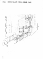
FIG,6
DRIVE
SHAFT
PIPE&
GEAR CASE
H
REFoNo.
P.P.N0.
" 0+002
8-003
0 +004
075-35300"800
086-35500-200
gOD-O210_-SZI
:8 +OOS
03_-3S50o-200
1_-008
091+35500-200
O +007
990+21o8o-1e2
!g92+11060-o42
8-008
8+009
gDO-21oHo-4021
O-OlO
902-10080+042
034-35500-201
8+Ol1
091-35500-200
H-o]a
H-013
031-35500_000
4-014
999-81000-000
0-015
032835500"2108
e-Ole
999"00102-209
e+o|1
171"35500-201
H-017
|73+35500-200
6-017
174-35S00_200
6-017
17S-35S00-200
6-018
g93*50010'-OOZ
_-010
017-38120+201
H-020
330-00_000210
0-020
330*00200-230
0 +020
330-00200-240
0-021
048°35500*202
Og9-O+O00+lO0
B +02_'
H-023
040-35500.200
0-02,1
999-08122-208
8-025
019"35500-20|
8 +028
012-35500+200
0:027
01]-35|00+200
6+028
+ 010-355S5-200
0-020
990-21060-182
6+030
992+11000-042
g_g-02|02-403
_+03!
0+032
0e3-3_500-2oo
m 0"032
I OO4-35500_Z00
8_032
I 005-35500-200
088_3_500_Z00
002-35500-200
0"033
8-_034
080-35300-200
081+35500+200
8-035
028-35S00*200
6 +036
025-35500-200
317+02000+200
6 "03B
UOO-2]OHO-OA2
0 -040
g99-62102*404
e.o37
i
I
!
rl
PARTS
NAME
ogo+35joo-uoo
DZI¥E.SIIAFT
:8-001
e-oz2
i
I
,]
PIPE
ASS'Y
9RIVE':-SHAFT
CONP,
BEAEIHQ
HOLDEi
CLiP
NEEDLE
8EA_]HG
tOJ5
DEALING
NOLDEE
OLIVE
SHAFT
PIP+
GASKET
BOLT OXIE
S.VASEEE
G
aOLT ax4o
S.VASKE_
g
OEA_ CASE tIOLDE_
DELVE + S+IAFT PIPE
GASKET
GEAR
CASE+AS$+Y
BALL
DEALING
16000
PLAIH
HEA||HG
OIL
SEAL 10228
PIOPELLEI
SIIAFT
SHIN
k
PROPELLEE
SHAFT
SHIN
k
PIOPELLEE
SHAFT SHIN
A
PEOPELLE!
SHAFT
SHIN
A
STOP RIHG
C-]O
EX
GEAZ
GEA!
SItAPT SIIIH
0.10
G[A|
SHAFT
SH]H
0+20
GEAI
SllAFT
SIllH
0,30
GEAI
CASE GA_AET
BALL BEAIrHG
_001
GEAI
CASE EOVEE
lUlL
SEAL
PIOPELLE2
|2227
SHAFT
SHEAR Plm
COTTEk
P|H
P_OPELI.EJ
80LT
8XI8
....
S.VASHE]
6
TIIEUST
BEA_ING
1024
O|IVE
SJIAFT SKI_
0.50
DELVE SHAFT
SHiN
O, lO
DELVE SIikFT
Stile
O+OS
IDIIVE
SHAFT
SHiH
0,20
PINION
COLLAE
PINION
PINION
PIN
4XIB
GEAr COLLAR
GEAE PIN
DRAIN
GASKET
Bflt.T EX8
•
TIIIUST
VASIIEE
IOZf
O'ty
It
2
I
2
2
|
I
I
1
I
l
1
O,lO
0.20
0.30
l+O
1
¥
Y
V
1
t
V
g
v
I
I
1
1
1
1
I
1
2
2
1
v
¥
Y
1
!
I
]
1
l,
1
2
FIG.7
TOOLS
ii!i ....
o.
REENo,
7-000
1-001
7-002
? -003
?-Q04
21
PARTS
..........
NAME.....
io',y
P.P.No.
g_5-3S3O4-QO0
851-20oo0-201
i808-2oo00-2oo
882-20000-200
948-32352-_00
TOOL
KIT
SPAK[
PLUG BOX
SPANNER
I0X13"
PLUS 9rIVER
4
TOOL BAG
SPANHE_
!
I
!
I
MODEL NO.
298.586191
For quick service or repair, take your Outboard
Motor to any Sears Service Unit throughout
the
U.S. and Canada
Each Service Unit is staffed
by trained
technicians,
using Sears approved
parts and repair procedures
to ensure that we
meet our pledge to you-"We
service what we
sell." Refer to the local telephone directory
for
the Sears Unit nearest you.
FULL ONEYEARWARRANTYON
OUTBOARDMOTOR
For One year from
this
outboard
tions
and
Manual
repair
workmanship
HOW TO ORDER REPAIR PARTS
board
motor,
if the
Refer to the Identification
Pfate for the comp]ete model number when requesting service or
replacement parts for your outboard motor.
All parts listed herein may be ordered
any Sears, Roebuck and Co.
from
i. Model Number
2. Part Number
PARTS,
ALINFORMA-
iN
JAPAN
for
tronic
material
in
or
the
out.
is used for
purposes,
only
com-
this
thirty
war-
days from
is available
outboard
trolling
Canada.
the
Sears
day of use.
the
motor
center
in
simply
or
elec-
to the nearest
the
Warranty
by
motor
United
is valid
Sears
States
Or
in country
of
purchase.
warranty
rights,
and
rights which
SEARS,
motor
Service
gives
you
you
specific
may
also
vary from
state
legal
have
other
to state,
SEARS,ROEBUCK'
AND CO.,
0EPARTMENT
698/731A
If the parts you need are not stocked locally,
your order will be electronically
transmitted
to a Sears Repair Parts Distribution
Center for
e'xP,edited handling.
_
PRINfED
appear
returning
This
3. Part Name
4. Quantity
in
which
Warranty
service
WHEN
ORDERING
REPAIR
WAYS GIVE THE FOLLOWING
TION:
defects
rental
applies
fhe first
in
followed.
free of charge.
Or
ranty
att instruc-
detailed
are
outboard
mercial
when
procedures
Owner's
will
the first day of use of
motor,
Sears Tower. Chica_o,
IL 60684
SEARSCANADA INC,
222
ROEBUCK
Jarvis
AND
St,
Toronto, 0ntar_o,
CO..
Chicago,
canada
IL 60684