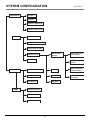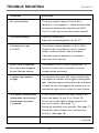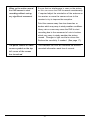
1
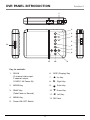
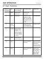
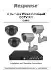
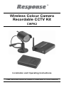
Wireless Colour Camera
Recordable CCTV Kit
CWFK2
Installation and Operating Instructions
These instructions should be retained in a safe place for future reference.
CONTENTS
1 INTRODUCTION
3
7 SYSTEM CONFIGURATION
18
2 KIT CONTENTS
5
8 TROUBLE SHOOTING
19
3 DVR FEATURES
5
9 TECHNICAL SPECIFICATION
21
4 INSTALLATION
6
4.1
System Connection
6
4.2
Camera Installation
7
4.3
Powering Up the System
8
4.4
Setting the Camera Channel
(Optional)
9
4.5
Setting the Receiver Channel
(Optional)
9
4.5
Camera and Interference
10
5 DVR PANEL INTRODUCTION
11
6 DVR OPERATION
12
6.1
Keys - Functions
12
6.2
Changing Between Real Time
Viewing and Playback Mode
13
6.3
Channel Selection
13
6.4
Manually Taking a Photo Shot
or a Video Clip
13
Menu Icons Definition
14
6.5
6.6
System Setup
14
6.6.1 Date / Time Setup
15
6.6.2 Motion Detection
and Advance Setup
15
6.7
Playing Back Recorded
Photos / Video Clips
16
6.8
Memory Overwrite Indication
17
6.9
Deleting Recorded Files
17
2
10 ACCESSORIES IN
THE RANGE
24
11 DISPOSAL – RECYCLING
INSTRUCTIONS
25
12 GUARANTEE AND
CUSTOMER HELPLINE
26
INTRODUCTION
Section 1
The Response Wireless Colour Camera Recordable CCTV Kit is a wireless monitoring
system designed to capture photos or 10 second video clips of any motion viewed by the
wireless camera and store them in memory on the 2 channel DVR. There is also an
additional video input available on the DVR to allow you to expand the system using a range
of CCTV accessories. The wireless camera supplied is colour, weatherproof and suitable
for day/night use for the protection of your home or office, etc.
Please read before you start:
Always use discretion when installing CCTV surveillance equipment especially
when there is perceived policy. Enquire regarding local regulations applicable
to the lawful installation of video recording / surveillance. Third party consent
may be required.
WIRELESS DEVICES OPERATING RANGE:
Ensure the signal reception viewed from the wireless camera is the best possible
reception (i.e. no interference lines viewed on the TV) between the camera and
receiver. If necessary reduce the distance between the camera and receiver to
prevent any interference on the picture. This is important to prevent the DVR
from capturing any unnecessary recordings of interference when set to motion
record. You may find that if the wireless camera is installed outside the property,
the maximum range without interference may be no more than 10m (provided
only a single brick wall acts as a barrier between the camera and receiver.
Other devices operating on the 2.4GHz frequency could affect the performance of
the product such as wireless routers, cordless phones or microwave ovens so
advised to keep away. Avoid placing the camera next to a metal panel radiator.
3
SAFETY AND INSTALLATION TIPS:
DVR
●
Keep away from heat sources and high temperature places
●
Avoid direct sunlight
●
Avoid humid places
●
Avoid vibration
●
Install in a ventilated environment
Camera(s) and DVR
Do not attempt to open the units with the power adaptor plug connected to avoid any risk
of personal injury.
When installing CCTV camera(s), always follow manufacturer’s advice when using power
tools, steps, ladders, etc. and wear suitable protective equipment (e.g. safety goggles) when
drilling holes. Before drilling holes through walls check for hidden electricity cables and
water pipes. The use of a cable/pipe detector is advisable.
When installing any cameras with this unit, it is advisable to use cable conduit to protect any
video / power extension cables from being exposed externally and to prevent/reduce the
chances of the cables being tampered with. After drilling any hole though an external wall
for a cable, ensure the hole is sealed up around the cable using a sealant to prevent drafts.
To prevent a fire or electrical shock hazard, do not attempt to open the housing while the
unit is exposed to rain, water or wet conditions. There are no user serviceable parts
inside. Refer servicing to qualified service personnel.
NIGHT VISION:
The camera has built-in infra-red LEDs to allow you to view at night for 24hrs
surveillance. The LEDs will automatically activate at night and the picture viewed will
turn to black and white.
4
KIT CONTENTS
Section 2
1 x Wireless Colour Camera
1 x Wireless Receiver unit
1 x 2 Channel DVR unit
1 x DIN to RCA adaptor lead assembly
1 x Video output cable for Wireless Receiver unit to 2 Channel DVR
(1m RCA to RCA cable)
1 x Video output cable for 2 Channel DVR to TV (1m RCA to RCA cable)
1 x Wireless Camera power supply adaptor (12VDC/300mA)
1 x Wireless Receiver power supply adaptor (12VDC/300mA)
1 x 2 Channel DVR unit power supply adaptor (12VDC/1.2A)
1 x SD memory card (2GB)
1 x Camera fixing kit - wall plugs and screws
1 x Installation and operating manual
1 x Window sticker
Tools Required:
Electric drill
5mm masonry drill bit
15mm masonry drill bit
No. 2 Philips screwdriver
3mm flat blade screwdriver
5
IMAGE RECORDER
(DVR) FEATURES
Section 3
●
2 channel video input/ 1 channel video output
●
SD card technology
●
Photos recorded in JPG format / video recorded in AVI format
●
Motion detection
●
Preset NTSC / PAL system input
●
Time and date stamp
●
Picture in picture display (view one camera channel in another camera channel)
6
INSTALLATION
Section 4
4.1 System Connection
TV / MONITOR
WIRELESS CAMERA
Camera Power
Supply Adaptor
Video Signal
to Input
WIRELESS RECEIVER
DC12V
POWER
VIDEO
Receiver Power
Supply Adaptor
DVR
Not used In
this model
DVR Power
Supply Adaptor
DIN IN
VIDEO IN 2
GDN
VIDEO IN 2
POWER IN
GND
VIDEO OUT
Key to DIN plug colours:
White plug – Camera channel 1
Yellow plug – Camera channel 2
Black plug – Video output
Red plug
– 12 V DC Power in
Connect the video output from the wireless receiver to the white plug (channel 1) of the
DVR. The red plug (channel 2) can be use with an additional wired camera accessory.
7
4.2 Camera Installation
Mount the camera in a selected location using the fixing screws and plugs supplied. If the
camera is installed outdoors on an external wall you will need to drill a cable entry hole of
around 15mm for the cable to pass through the wall. Feed the camera’s cable through the
cable entry hole into the property, so that all connections are made inside.
Ensure that there is a mains power socket internally located near to the camera for power.
After installing the camera, seal the cable hole using a suitable sealant to prevent drafts.
2.4
GHz
Weather-proof
HORIZONTAL
SURFACE MOUNT
Loosen this nut by hand and
unscrew the bracket if ceiling
mounting is desired
Bracket
WALL MOUNT
Note: in this mounting position,
the Camera body needs to be
slightly tilted to prevent the
antenna from touching the wall
CEILING MOUNT
2.4
GHz
Weather-proof
8
The sun shade hood can be removed from the camera body and re-attached for installation
flexibility. This is done by sliding along the body of the camera as shown.
2.4
GHz
Weather-proof
4.3 Powering up the system
1.
Insert the SD card into the DVR if not already fitted
2.
Power up the camera
3.
Power up and turn ON the receiver
4.
Turn ON the DVR using the power switch
5.
Tune your TV to auxiliary (AUX), A/V or video mode to view the camera.
(Note: Refer to your TV/VCR/DVR’s owner’s manual for setting this up).
6.
Adjust the camera viewing position again if necessary.
Note: By default the camera and receiver will be set to channel 1. If poor reception is
received by the wireless camera and adjusting the orientation of the receiver’s antenna
doesn’t help, then set the camera to another unused channel. See 4.4 below.
9
4.4 Setting the Camera Channel (Optional)
The wireless camera has 4 selectable channels to avoid any interference from any other
wireless devices. Follow the steps below to set or change the frequency channel of the
camera. If you are adding another camera to link with the supplied receiver in this kit, then
ensure its channel is set to a different channel to the existing camera(s).
1 2
1.
Pull open the rubber flap on the camera’s power cable.
2.
Locate the 2 dip switches under the rubber flap.
3.
Set the camera channel as per the switch configuration
below using the DIP switch tool provided. Do not set
multiple cameras on the same channel or interference
may appear on screen.
Channel
1
Channel
2
Channel
3
Channel
4
DIP Switch Tool
1
2
1
2
1
2
1
2
4.5 Setting the Receiver Channel (Optional)
The wireless receiver is capable of receiving up to 4 separate channels. The front of the
wireless receiver has 4 LEDs representing the 4 channels of the receiver. When lit, the
LED will indicate which channel is currently being displayed. In the diagram below CH1
is lit up indicating channel 1 will be displayed on the screen.
The wireless receiver allows you to manually switch between active channels by pushing
the SET button. (The orientation of the channels when pressing the ‘SET’ button each
time is CH1 to CH2 to CH3 to CH4 and back to CH1).
Channel SET Button
CH1
CH2
CH3
CH4
Channel Indicator Lights
10
SET
4.6 Camera and Interference
The wireless camera operates on the 2.4GHz frequency. Some devices such as wireless
broadband routers, microwaves, cordless phones can cause interference and affect picture
quality as they use the same frequency. If you are experiencing interference or poor image
quality try the following steps:
- move or orient the camera in a different location.
- adjust the receiver’s antenna.
- limit the number of walls, floors between the camera and receiver as this can
dramatically alter picture quality.
- dense materials such as concrete or metal will impede the wireless signal; move the
camera and/or receiver away from dense materials. A metal radiator is an example.
- if possible keep the camera and receiver away from or move conflicting devices such
as wireless routers, microwaves, cordless phones.
- make sure all Cameras are set to different channels.
- disconnect all other wireless devices to find out which is causing the problem and
adjust your setup accordingly.
- some wireless signals may originate from nearby homes or businesses; in this case a
wired camera may be necessary.
11
DVR PANEL INTRODUCTION
Section 5
1
2
3
MODE
POWER
SNAP
STATUS
5
MENU
12
DISP
6
7
8
11
9
10
Key to controls:
1.
DIN IN
6.
DISP (Display) Key
7.
Up Key
12VDC/1.2A Power IN)
8.
Right Key
2.
MODE Key
9.
●
Enter Key
3.
SNAP Key
10.
Down Key
11.
Left Key
(2 channel video input;
2 channel output;
(Take Photo or Record)
4.
MENU Key
5.
Power ON / OFF Switch
12. SD Card
12
POWER
4
DVR OPERATION
Section 6
6.1 Keys - Functions
Reference
to diagram
Key
Real time mode
(Live viewing)
Play back mode
2
Mode
Switch to play
back mode
Switch to real
time mode
4
Menu
Setup menu
Delete files menu
appears (for video
clips, the Menu key
only functions at the
beginning or end of
a clip)
Exit setup menu
9
Enter
(or OK)
Display full screen
of a selected photo
shot or exit full screen
Confirm an item
6
Display
Switch between
channel 1 and
channel 2. If in
photo mode then
view one channel
in another (picture
in picture)
3
Snap
Take a photo or
record a video Clip
11
Left
Move to left photo /
video clip
Move to left item.
Select the motion
detect area.
Move the motion
detect area to left
8
Right
Move to right photo /
video clip
Move to right
item. Select the
motion detect
area. Move the
motion detect
area to right
13
Setup menu
7
Up
Motion detect
ON/OFF (Indicated
on the top left of
the TV/monitor by
an ‘eye’ sign)
Move up to a photo /
video clip. Before
playing back a file,
the on screen display
details can be
removed or restored
Move the motion
detect area /
sensitivity up
when adjusting
10
Down
Select photo or
video record mode
(Indicated on the
top left of the
TV/monitor by a
photo camera or
video camera sign
Move down to a
photo/video clip.
Play back a selected
video clip
Move the motion
detect area /
sensitivity down
when adjusting
6.2 Changing Between Real Time Viewing
and Playback Mode:
By default the DVR is set to view real time and will display channel 1 when powered ON.
Press the MODE key to switch between real time and playback mode.
6.3 Channel Selection:
1.
Press DISP to change from channel 1 to channel 2.
2.
Press DISP again to view channel 2 in channel 1 (only the when DVR is set to photo
record mode).
3.
Press DISP again to view channel 1 in channel 2 (only when the DVR is set to photo
record mode).
4.
Press DISP again to return to channel 1 (only when DVR is set to photo record mode).
Note: In photo record mode, when one channel is viewed in another channel, the DVR
will only record from the main viewing channel. In video record mode, it is not possible to
view one channel in another.
6.4 Manually Take a Photo Shot or Video Clip:
Press the Down key to select photo or video mode. On the top left corner of your TV / monitor,
you will see either the photo camera or video camera icon depending on your selection.
Press the SNAP key to capture a photo or video clip (fixed 10 second clip).
14
6.5 Menu Icons Definition:
Setup Screen
Date Time Setup
Advance Setup
Motion Detect On or Off
Quit Menu
Select Photo or Video
Advance Setup
Select TV System,
NTSC or PAL
Select Image Quality
High or Low
Motion Detect
Area Setting
Motion Detect Count
Motion Detect
Interval Setting
Motion Detect
Sensitivity
Photo Management
Format Memory,
Clear All Files
Delete One Photo
Delete All Photos
6.6 System Setup:
1.
During real time mode, press the MENU key to enter the setup menu.
Setup Screen
15
6.6.1 Date/Time Setup
1.1
1.2
Use the left / right key to select the ‘Time Setup’ icon and press enter.
Use the left / right key to select the date or time. Use the up / down key
to set the correct digit.
1.3
Press enter to confirm settings.
6.6.2 Motion Detection and Advance Setup
When the DVR is set to motion detect, it records the photo or video by sensing any
change in picture from the selected camera and stores on to an SD memory card.
Although two cameras might be connected to the unit, it will only record from the
selected camera channel. The time and date of the capture are also recorded.
1.4
Use the left/right key to move to the ‘Motion Detect’ icon and press enter to
enable / disable auto capture.
1.5
Use the left/right key to move to the ‘Capture Format’ icon and press enter to
select ‘Photo’ or ‘AVI’ (video). Note that the AVI video clips are fixed at
a 10 second period.
1.6
Use the left/right key to move to the ‘Setup’ icon and press enter.
1.7
Press enter to select the TV system, NTSC or PAL.
1.8
Use the left / right key to move to the image ‘Quality’ icon and press enter to
select high or low quality.
1.9
Use the left / right key to move to the ‘Motion Detect Area (M)’ icon and press
enter. Use the left / right key to select the detection area (full / middle / small
area). Press enter to confirm the setting.
1.10 Use the left / right / up / down key to move the chosen detect area to a desired
target position. Press enter to confirm the setting and exit the area setup.
1.11 Use the left / right key to move to the ‘Motion Detect Count’ icon. This is used
to set the number of photos the DVR will take for every trigger when the DVR
is set to photo capture mode. The settings are 1 / 3 / 5 photo shots. Press enter
to select the required number of shots.
16
1.12 Use the left / right key to move to the ‘Motion Detect Interval’ icon. For photo
capture format mode only, this is used to set the interval break in seconds
between each capture (for example, if set to 5, then after the first trigger, it
would take 5 seconds for the DVR to trigger again). Press enter to select 1 / 3 / 5
seconds. It is recommended to set to 1 for maximum event capture.
1.13 Use the left/right key to move to ‘Motion Detect Sensitivity’ icon and press
enter. The sensitivity range is 1 ~ 99. The larger the value the lower the
sensitivity. Use the up/down key to adjust the ‘Target Value’ to the desired
setting. The recommended setting is 10, however observe if this is too sensitive.
Movement is captured by the change in picture displayed on the TV / monitor in the
selected area. If there are any changes in light such as a reflections, movement of
tree branches, bushes for example, this can cause the system to start recording,
although no approaching objects/persons may be seen during playback.
If the
sensitivity is set too high, natural activity such as rain for example may cause the
system to start recording. It is also ideal to point the camera way from trees, bushes
that might be affected by the wind. If any unnecessary photo/videos are captured
adjust the sensitivity lower and observe.
If this DVR at any stage is used with a Wireless Camera and Receiver Kit ( CWFK1)
to receive wireless video, ensure this video viewed on the TV is the best possible
reception (i.e, no interference lines viewed on the TV) between the camera and
receiver.
If necessary reduce the distance between the camera and receiver to
prevent any interference on the picture. This is important to prevent the DVR from
capturing any unnecessary recordings of interference when set to motion record. You
may find that that if the wireless camera is installed outside the property, then
maximum operating range without interference may be no more than 10m (provided
only single brick wall acts as a barrier between the camera and receiver).
6.7 Playing Back Recorded Photos / Video Clips:
The photos or videos captured will be stored in different folders for easy searching. The
folders are named according to the date sequence. If there are no file(s) in the memory,
the DVR will display ‘NO FILE’ and return to real time viewing mode.
1.
Press the MODE key to enter or exit playback.
2.
Press the enter key to enter thumbnail view. Press again to enter full screen normal view.
17
3.
Use the left / right key to move back or forward to an image or video clip.
4.
To play back a video, press the Down key in full screen mode to play the video file
5.
In full screen view, press the Up key to turn ON / OFF the on screen display information
(date, time, capture number, etc). For video files ensure you select this before playing
back the file.
6.
Press DISP to view any folders and Up / Down keys to scroll to a folder and press enter
to select.
6.8 Memory Overwrite Indication:
When the memory has reached its maximum storage capacity, any further files captured
will overwrite the earliest file stored. When the system is overwriting the earliest file, this
is indicated by the colour of the photo camera or video camera sign on the top left corner
of the TV / monitor. It will turn red when overwriting.
6.9 Deleting Recorded Files:
Delete Menu
In play back mode, press the MENU key.
Use the left / right key to move to the required icon to delete the current image (‘Delete
One’ icon), delete all files in the current folder (‘Delete All’ icon) or delete all files stored
in memory (‘Format’ icon).
Press enter to display the tick or cross options for an icon on the screen. Use the left / right
key followed by the enter key to select the chosen option.
18
SYSTEM CONFIGURATION
Preview Mode
Section 7
Camera 1
Camera 2
Camera 1 (Camera 2)
Camera 2 (Camera 2)
MENU
Date Time Set up
Motion Detect On or Off
Select Photo or Video
Motion Detect
Settings
Advance Set up
Quit Menu
Playback
MENU
Motion Detecting
Area Setting
Motion Detecting
Count
Single Picture Display
HQ / LQ
6 Picture Display
PAL / NTSC
File Browse
Quit Menu
Delete One Photo
Delete All Photos
Format Memory
19
Motion Detecting
Interval Setting
Motion Detecting
Sensitivity
TROUBLE SHOOTING
Section 8
PROBLEM
SOLUTION
No camera picture
The power supply adaptor for the DVR or
camera(s) is not plugged in. Check all video cable
connections between the camera(s) and DVR.
The TV is not tuned to view the correct channel.
Poor picture quality
Clean the camera lens.
Adjust the contrast/brightness on the TV.
Interference is seen
The wireless camera operates on the 2.4GHz
on the TV
frequency like many devices such as wireless
routers, cordless phones, and microwaves.
If possible keep the camera(s) and receiver
away from these devices.
Some colours viewed by
The camera’s lens is a CMOS type sensor. Its
the camera do not appear
limitation is that it will not produce all colours
to look like true colours
viewed outside accurately.
A white image appears
The camera’s infra-red LEDs shine invisible light
at night
that reflects of surfaces such as glass causing white
light. Place the camera on the other side of windows
or place the lens flush against the surface to try to
improve the night vision or place in a well lit area.
DVR doesn't automatically
Ensure Motion Detection has been setup in the
record when set to motion
menu (see pages 13 and 14 or 15 and 16).
record when movement
Ensure the correct ‘Motion Detect Interval’ has
is captured
been set correctly. (See page 17).
Ensure the sensitivity is set correctly. (See page 17).
Ensure the ‘Motion Detect Area’ has been set
correctly. (See page 16).
continued
20
When set to motion record,
Ensure that no interference is seen on the picture
the DVR seems to start
as this can cause the DVR to record unnecessarily.
recording without seeing
If required adjust the orientation of the antenna on
any significant movement
the receiver or move the camera closer to the
receiver to try to improve the reception.
Point the camera away from tree branches or
bushes which may sway in windy weather conditions.
Heavy rain or snow may cause the DVR to start
recording due to the movement of rain in bushes
which may sway in windy weather the picture
viewed. Changes in light could also cause this.
Reduce the sensitivity if needed. (See page 17).
The photo camera or video
This indicates the DVR will overwrite the earliest
camera symbol on the top
recorded information each time it records.
left corner of the screen
has turned red
21
TECHNICAL SPECIFICATION
Section 9
ITEM
2 CHANNEL DVR
Video format
PAL / NTSC
Video input
2 channel (NTSC / PAL) (RCA)
Video output
1 channel (NTSC / PAL)
Composite video output
Video display
Single picture or picture in picture display
Display resolution
JPEG VGA: 640 x 480
AVI QVGA: 320 x 240; 5fps for 10 seconds
Compression method
JPEG
Image quality
High / Low
Motion detection
Programmable area and sensitivity settings
Hard disk
1 x Internal SD card
Storage capacity
Maximum 2GB SD card stores up to 20,000 photos
and or records up to 12 hours of video per channel
Alarm output
Active low power signal output when motion
is detected
Power supply
12V DC/1.2A output power supply adaptor
Power consumption
2.5W max.
Dimension of DVR (L x W x H)
140 x 100 x 25mm
Operating temperature
0 to 40°C
22
ITEM
WIRELESS CAMERA
Image sensor
1/3” CMOS
Pixel resolution
PAL:
628 x 582
NTSC: 510 x 492
380 TV lines
Lens size
6mm
Viewing angle
60°
Night vision range
Up to 7m
Number of infra-red LEDs
11
Day / night mode
Colour during the day / switches to B&W at night
Minimum illumination
5 Lux when the IR lamps are turned on
Signal
Analogue
Maximum transmission range
100m (open field range)
Operating frequency
2.4000 GHz – 2.4835 GHz
Channels
4
IP rating
IP54
Operating temperature
- 10°C to 50°C
Power supply
12 VDC / 300mA
Dimensions (H x W x D)
102 x 52 x 102mm
Weight
214g
23
ITEM
WIRELESS RECEIVER
Operating frequency
2.4000 GHz – 2.4835 GHz
Channels
4
Signal
Analogue
IP rating
IP40 - Internal use only
Video
NTSC / PAL
Power supply
12V DC/1.2A output power supply adaptor
Video output interface
RCA sockets
24
ACCESSORIES IN THE RANGE
Section 10
There are a range of accessories available in the Response CCTV product range to expand
your system:
CWK1
Wired Colour Camera CCTV Kit
CA2
LCD Screen for Wireless / Wired CCTV Kits
CWFK1
Wireless Colour Camera CCTV Kit
CA3
Wireless Colour Accessory Camera
(requires CWFK1 CCTV KIT to operate)
CA5
Professional Heavy Duty Camera CCTV Kit
CA6
Dummy Professional Heavy Duty Camera
CA7
4 Channel DVR Recorder Kit
CA8
Wired Internal Colour Dome Camera CCTV Kit
CA9
Dummy Internal Dome Camera
CA10
Heavy Duty Colour Camera CCTV Kit
CA11
Dummy Heavy Duty Camera
CA4
10m Extension Cable Kit
CA12
20m Extension Cable Kit
Note: The maximum extension cable length for any wired camera with this system is 30m
without reducing the picture quality of the video.
25
DISPOSAL – RECYCLING INSTRUCTIONS
Directive (2002/96/EC)
This product is classified by the Waste Electrical or Electronic
Equipment (WEEE) Directive. It should not be disposed of with other
household or commercial waste.
At the end of its useful life the
packaging and product should be disposed of via a suitable recycling
centre.
For information on available facilities, please contact your
local authority or the retailer from where the product was purchased.
26
Section 11
GUARANTEE
Section 12
Novar ED&S undertakes to replace or repair at its discretion goods (excluding non
rechargeable batteries) should they become defective within 1 year solely as a result of
faulty materials and workmanship.
If the product has not been installed, operated or maintained in accordance with the
instructions, has not been used appropriately or if any attempt has been made to rectify,
dismantle or alter the product in any way the guarantee will be invalidated.
The guarantee states Novar ED&S entire liability. It does not extend to cover consequential
loss or damage or installation costs arising from the defective product. This guarantee does
not in any way affect the statutory or other rights of a consumer and applies to products
installed within UK and Eire only.
If an item develops a fault, the product must be returned to the point of sale with:
1. Proof of purchase.
2. A full description of the fault.
3. All relevant batteries (disconnected).
Response is a trademark of Novar ED&S.
CUSTOMER HELPLINE
Most issues can be solved over the phone in a few minutes.
Please contact our Helpline Team on the number below for any
installation and general advice regarding our products:
0844 736 9149
Lines open 9.00am to 5.00pm, Monday to Friday.
Calls charged at service providers national rate.
27
Novar Electrical Devices and Systems Limited. (A Honeywell Company)
The Arnold Centre, Paycocke Road, Basildon, Essex SS14 3EA. UK
www.friedland.co.uk
© Novar Electrical Devices and Systems Limited. 2009
50043920 Rev.B