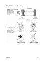
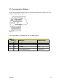
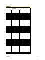
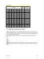
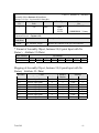
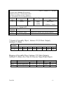
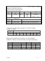
1
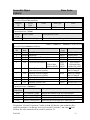
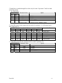
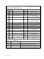
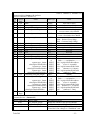
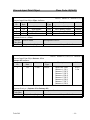
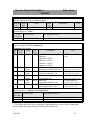
Intellis
DeviceNet Network Monitor
Models 7604, 7644 & 7679
Installation and Operation Manual
Revision History
Revision 1.0
1 June, 2004
Initial Version
Revision 1.1
10 February, 2005
Document was updated to reflect new PCB design, addition of pneumatic section, misc.
corrections and changes in IOM format.
Revision 1.2
7 August, 2006
Changed note 9 in Class Code 9 of Appendix B
Tech-309
1 Introduction
Scope of Manual
1-2
Symbols Used in this Document
1-2
About DeviceNet
1-2
Westlock Intellis DeviceNet Module EL-40092
1-3
Module Bit Map
Watchdog Timer
LED Status Indicators
EL-40092 Module Layout
Device Specifications
Specifications
DeviceNet Features
EL-40092 Current Consumption
Tech-309
1-4
1-4
1-5
1-7
1-7
1-7
1-8
1-8
1-1
1.1 Scope of Manual
This manual contains installation, configuration and specification data for the DPAC
DeviceNet valve controller.
This manual assumes a basic level of familiarity and competence with DeviceNet
terminology and technology. Only qualified personnel should install, operate and
maintain this equipment.
1.2 Symbols Used in this Document
This symbol warns the user of possible danger. Failure to heed this warning
may lead to personal injury or death and/or severe damage to equipment.
This symbol identifies information about operating the equipment in a
particular manner that may damage it or result in a system failure. Failure to
heed this warning can lead to total failure of the equipment or any other
connected equipment.
This symbol draws attention to information that is essential for understanding
the operation and/or features of the equipment.
1.3 About DeviceNet
DeviceNet is an open network standard originally developed by Allen-Bradley and based
on a broadcast oriented, communications protocol - the Controller Area Network (CAN).
The CAN protocol was originally developed by BOSCH the European automotive market
for replacing expensive, wire harnesses with a low-cost network.
In 1995 Allen-Bradley released the protocol to the open DeviceNet Vendors Association
(ODVA). ODVA oversees the development of the DeviceNet specification and the
conformance testing of DeviceNet products. ODVA is open to any manufacturer or user
of this protocol with a worldwide membership of over 250 companies.
DeviceNet is a simple networking solution that reduces the cost and time required to
install and wire industrial automation devices. A single DeviceNet Intellis System will
accommodate up to 63 valves and 1008 discrete I/O points. Although a simple system to
Tech-309
1-2
design and implement, DeviceNet has the capability to interconnect complex as well as
simple devices to the same network, easily accommodating both analog and discrete I/O.
Westlock Controls is a member of ODVA and our DeviceNet products are conformance
tested and certified.
1.4 Westlock Intellis DeviceNet Module EL-40092
The EL-40092 module is a 4 input, two output network monitor. Inputs 0 and 1 are
internal Hall Effect sensors that are activated by the field of a magnet (south pole). Inputs
2 and 3 are active high/low (activated by pulling the input up to +24V or activated by
pulling the input down to ground). The outputs are open drain active low FETs, fused
(solid state self resetting) at 0.2A with diode protection to 24Vdc. For current
consumption see Table 6, page 1-8. Minimum power supply input voltage is 19Vdc to
insure proper solenoid operation.
Connection to the network is via DeviceNet specific cable. There are both Round and
Flat Media Refer to the Allen-Bradley document “DeviceNet Cable System”’ (Cat. No.
DN-6.72) for a detailed treatment of this topic.
For data exchange to occur each network monitor connected to the DeviceNet network
must be programmed with a unique address, numbered between 0 and 63 and all nodes
must be set to the same Baud rate as the scanner. This may be accomplished via setting
the DIP switch, S1, on the electronics module.
The address and Baud rate may also be set via explicit Messaging if positions 7 and 8 on
S1 are set to the “On” position. Refer to Section 3.1, page 3-2 for additional information.
It is possible to exchange or add slaves during normal operation without interfering with
communications to other nodes.
The Westlock Controls Corp. DeviceNet Module, EL-40092, operates as a GROUP 2
Only Slave on a DeviceNet network. The unit supports Explicit Messages and Polled I/O
Messages of the Predefined Master/ Slave Connection Set. The device does not support
the Explicit Unconnected Message Manager (UCMM).
Refer to Section 1.5 Device Specifications, page 1-7, for a summary of features.
Tech-309
1-3
1.4.1 Module Bit Map
Table 1
I/O
TYPE
MODULE REFERENCE
INPUT 0
Hall Effect
Internal Sensor
INPUT 1
Hall Effect
Internal Sensor
INPUT 2
INPUT 3
Active High/Low*
Active High/Low*
J2-1 (In Hi/Low) to J2-2 (Ground)
J2-3 (In Hi/Low) to J2-4 (Ground)
BITMAP OF DATA
INSTANCE #4 (8-POINT INPUT WITH
NO STATUS) ATTRIBUTE #3 (DATA)
BYTE 0, BIT 0 Valve Closed
(Bottom L.S.)
BYTE 0, BIT 1 Valve Open
(Top L.S.)
BYTE 0 BIT 2 Aux. Input
BYTE 0, BIT 3 Aux. Input
*Active High/Low indicates that pulling the input pin up to +U or down to ground activates the input.
BITMAP OF DATA
I/O
TYPE
MODULE REFERENCE
INSTANCE #33 (STATIC OUTPUT)
ATTRIBUTE #3 (DATA)
OUTPUT 0
Active Low*
J4-1 (+24V) to J4-2 (Out)
OUTPUT 1
Active Low*
J4-3 (+24V) to J4-4 (Out)
BYTE 0, BIT 0 “A” Solenoid
BYTE 0, BIT 1 “B” Solenoid or
Aux. Output
*Active Low indicates that when the output is activated it pulls the pin down to GND drawing current through the load from the +24V
1.4.2 Watchdog Timer
The DeviceNet Connection Object (Class Code 05) of the DPAC firmware has an
integral inactivity/watchdog timer (IWT). The behavior of the IWT is defined by the
DeviceNet Specification.
There are two types of message connections, Explicit and I/O, each with their own IWT.
There are also different configurable attributes that effect device behavior in the event of
an IWT timeout.
The initial timeout value is the expected_packet_rate attribute multiplied by 4 or by 10
seconds, which ever is greater (Configuring state). All subsequent activations of the IWT
use the expected_packet_rate attribute multiplied by 4 as the number of milliseconds to
load into the IWT (Established state).
The default configuration of the DPAC will cause the outputs of the DPAC to go to
the de-energized state when either IWT times out.
The IWT attribute for the Explicit message connection is configurable via explicit
messaging. There are two values for this attribute supported by the DPAC; Auto Delete
(the factory default setting) and Deferred Delete. Refer to Table 2 for definitions of these
values and refer to Appendix B for the Device Specification to obtain Class, Instance,
Attribute codes for explicit messaging the device.
The DeviceNet Discrete Output Point Object (Class Code 09) controls the behavior of the
DPAC outputs. There are four attributes that specify the behavior of the device when
either a Fault state (IWT timeout) or Idle state (Poll message without data) is entered. The
DPAC may be configured to execute the Fault Value, outputs “ON” or “OFF”, or to keep
at last value. Refer to Appendix B for the Device Specification for additional
information.
Tech-309
1-4
Table 2
Value
1
3
Meaning
Auto Delete: The Connection Class automatically deletes the Connection if it
experiences an IWT timeout. This is the default value for this attribute with respect to
Explicit Messaging Connections
Deferred Delete: The Connection transitions to the Deferred state if any child
connection instances are in the Established state. If no child connection instances are
in the Established state the connection is deleted. This value is invalid for I/O
Messaging Connections.
1.4.3 LED Status Indicators
The LEDs provide information concerning the status of inputs, outputs, the
module and/or the network. The LEDs provide visual indication whether any
inputs or outputs are active and whether the module or network is in a fault
condition. The I/O Status LEDs are intended to indicate the state of the inputs
and outputs only.
Refer to Table 3, page 1-6, for more information.
Tech-309
1-5
Table 3
Module
p/n
LED
Module
Status
LED 1
Network
Status
LED 2
EL40092
Closed LS
IN_0 LED
Open LS
IN_1 LED
Aux. Input
IN_2 LED
Aux. Input
IN_3 LED
Output
OUT_0
LED
Output
OUT_1
LED
Tech-309
State
Indicates
Off
Green
There is no power applied to the device.
Device is operating in a normal condition.
The device Needs commissioning due to
Flashing Green
configuration missing, incomplete or incorrect.
Red
Unrecoverable fault, device may need replacing.
Flashing Red
Recoverable fault.
Off
Not powered/ Not online
For a Group 2 Only device: Device is allocated to
Green
Master
Online, not connected. For a Group 2 Only device:
Flashing Green
Device is not allocated to a Master
Failed communication device. The device has
detected an error that has rendered it incapable of
Red
communication on the network (Duplicate MAC ID
or Bus-off).
One or more I/O connections are in the Time-out
Flashing Red
state.
Input 0, Bottom L.S. Closed: Valve is in the
closed position as determined by the triggering of
Yellow
the Internal Hall Effect sensor by the travel of the
trigger mechanism on the shaft assembly.
Input 1, Top L.S. Closed: Valve is in the open
position as determined by the triggering of the
Yellow
Internal Hall Effect sensor by the travel of the
trigger mechanism on the shaft assembly.
Input 2, Active: Dry contact type switch attached
Yellow
to this input is closed.
Input 3, Active: Dry contact type switch attached
Yellow
to this input is closed.
Yellow
Output 0. “A” Solenoid is energized.
Yellow
Output 1. “B” Solenoid is energized.
1-6
1.4.4 Module Layout
J1
Figure 1- EL-40092
1.5 Device Specifications
1.5.1 Specifications
Table 4
Round Physical Media
Flat Physical Media
Supported Topology
Maximum Trunk Distance
Maximum Nodes/Network
Maximum I/O Points/Network
Typical Current
Consumption/Network Monitor
Host System’s Interface
Communications Method
Error Checking
Redundancy
Valve Specific Diagnostics
Tech-309
Shielded 2 twisted pairs for communication and power
Unshielded 4 parallel conductors for communications
and power
Trunk and drop
Round Media: 500m (1640’) @ 125 kbd
Flat Media: 420m (1378’) @ 125 kbd
64, one being the master
378, 4 inputs and 2 outputs/DPAC
75 mA with single Falcon NI solenoid energized
80 mA with single Falcon XP solenoid energized
Allen-Bradley, Omron, Emerson and many others
Group 2 only slave
CRC
No
No
1-7
1.5.2 DeviceNet Features
Table 5
DeviceNet Features
Device Type
Explicit Peer to Peer Messaging
I/O Peer to Peer Messaging
Configuration Consistency Value
Faulted Node Recovery
Baud Rates
Master/Scanner
I/O Slave Messaging
• Bit Strobe
• Polling
• Cyclic
• Change of State (COS)
Generic
No
No
No
No
125K, 250K, 500K
Yes
No
Yes
No
No
1.5.3 Current Consumption
Table 6
Inputs Active
Outputs Active Current Draw1
0
0
50mA
4
0
62mA
4
1
80mA
4
2
100mA
4
1
85mA(XP)
4
2
110mA(XP)
1
All current values acquired using a non-incendive
solenoid except where noted by an XP (explosion
Tech-309
1-8
2 Installation Instructions
Mounting
2-2
Pneumatic Connections
2-3
Tubing and Fittings
Porting
Maintenance
2-3
2-4
2-4
Switch Adjustment
2-5
Wiring Instructions
2-6
Wiring Diagram
DPAC Connector Pin-out Diagrams
2-7
2-8
DeviceNet Cabling Information
2-9
DeviceNet Supported Topologies
2-9
Tech-309
2-1
IMPORTANT: If the valve monitor is already in the field mounted on an actuator
and valve, please follow the field wiring instructions in Section 2.4.
Confirm that the area is known to be non-hazardous before opening the
cover of a network monitor and making or breaking any electrical connections.
2.1 Mounting
For steps 1-3 refer to Figure 2 below.
1. Attach the proper mounting bracket and adapter (if required) to the valve monitor
housing with the hardware provided.
2. Operate the actuator to full closed position.
3. Attach the valve monitor and mounting bracket to the actuator.
4. Note the position of the actuator/valve and confirm the Beacon position is
properly aligned, as shown in Figure 3 below while replacing the cover.
Figure 2
Tech-309
2-2
Figure 3
2.2 Pneumatic Connections
Personal injury and/or property damage may occur from loss of process
control if the supply medium is not clean, dry oil-free air or non-corrosive gas.
Instrument quality air that meets the requirements of ISA Standard S7.3-1975 is
recommended for use with pneumatic equipment in process control environments.
Westlock Controls recommends the use of a 20 micron filter with all Falcon solenoids.
2.2.1 Tubing and Fittings
The use of copper, stainless steel, nylon or polyethylene tube is recommended for piping
up air circuits and equipment. As a general rule, pipe threaded fittings should not be
assembled to a specific torque because the torque required for a reliable joint varies with
thread quality, port and fitting materials, sealant used, and other factors. The suggested
method of assembling pipe threaded connections is to assemble them finger tight and
then wrench tighten further to a specified number of turns from finger tight. The
assembly procedure given below is for reference only; the fitting should not be over
tightened for this will lead to distortion and most likely, complete valve failure.
1. Inspect port and connectors to ensure that the threads on both are free of dirt,
burrs and excessive nicks.
Tech-309
2-3
2. Apply sealant/lubricant or Teflon tape to the male pipe threads. With any sealant
tape, the first one or two threads should be left uncovered to avoid system
contamination.
3. Screw the connector into the port to the finger tight position.
4. Wrench tighten the connector approximately 1 - 2 turns (to seal) from finger tight.
Again this is only reference - the fitting should NOT be over tightened.
2.2.2 Porting
Figure 4
2.2.3 Maintenance
Routine maintenance is usually confined to the periodic replenishment of Dow Corning
III lubricant or equivalent to spool and spring.
Tech-309
2-4
2.3 Switch Adjustment
Switches are factory set. If you need to adjust switches for any reason follow
instructions below.
For steps 1-8 refer to Figures 1 and 5.
1. Refer to Figure 1 and note the approximate locations of the Open and Close
targets on the DPAC module.
2. With the valve in the closed position, lift bottom cam of the Close sensor trigger.
3. Turn cam until face of trigger is perpendicular to the target and sensor is activated
as evidenced by the lighting of the corresponding module LED.
4. Release the cam and the spring will push cam back onto the splined shaft.
5. Operate the actuator to the opened position.
6. Push down the top cam of the Open sensor trigger.
7. Turn cam until face of trigger is perpendicular to the target and sensor is activated
as evidenced by the lighting of the corresponding module LED.
8. Operate actuator from one extreme to the other several times to check Limit
Sensor operation.
Figure 5
Tech-309
2-5
2.4 Wiring Instructions
All wiring must be in accordance with National Electrical Code
(ANSI-NFPA-70) for the appropriate area classifications.
All wiring must be in accordance with National Electrical Code (ANSINFPA-70) for area classifications. The valve monitors are approved as nonincendive for
Class I, Division 2, Groups A,B,C and D; dust-ignition proof for Class II/III, Division 1,
Groups E,F and G hazardous (classified) locations; indoor/outdoor (NEMA type 4, 4X).
Always check the nameplate to make sure the agency approval ratings
coincide with the application.
The proper wiring diagram for your unit is shown on the inside of the enclosure
cover.
1. Wiring options for 7604, 7644 and 7679 are shown in Figures 6 and 7 below.
2. Replace the electronics housing cover or junction housing cover.
3. Unit is now ready for automatic operation. If any assistance is required, please
call Westlock Controls at (201) 794-7650.
Tech-309
2-6
Tech-309
2-7
2.4.1 DPAC Connector Pin-out Diagrams
Tech-309
2-8
2.5 DeviceNet Cabling Information
Correct termination of the trunk and total trunk and drop limits for the baud rate
the network is to run at must be observed or unreliable operation may result.
Table 7
Data Rate
125 kbd
250 kbd
500 kbd
Maximum Distance
Flat Cable
Thick Cable
420m (1378’)
500m (1640’)
200m (656’)
250m (820’)
75m (246’)
100m (328’)
Med. & Thin Cable
100m (328’)
100m (328”)
100m (328’)
Table 8
Data Rate
125 kbd
250 kbd
500 kbd
Maximum Cumulative Drop Length
156m (512’)
78m (236’)
39m (128’)
2.6 DeviceNet Supported Topologies
Figure 14
Tech-309
2-9
3 DPAC Configuration
Communication Settings
Baud Rate and Address via the DIP Switch
Baud Rate and Address via the Bus
Tech-309
3-2
3-2
3-4
3-1
3.1 Communication Settings
For the appropriate DIP switch settings for the address and baud rate of the DPAC refer
to Figure 15 and Tables 9 and 10.
Figure 15
3.1.1 Baud Rate and Address via the DIP Switch
Table 9
Switch S1
SW8
SW7
OFF
OFF
OFF
ON
ON
OFF
ON
ON
Tech-309
Baud Rate
Returned Value
125 Kbd
250 Kbd
500 Kbd
Default 125 Kbd or last value set via
bus (see Section 3.1.2)
0x00
0x01
0x02
0x00 (default) or 0x01
to 0x02 if set
3-2
Table 10-a
Switch S1
MAC
ID
Returned
Value
0
1
2
3
4
5
6
7
8
9
10
11
12
13
14
15
16
17
18
19
20
21
22
23
24
25
26
27
28
29
30
31
31
32
33
34
35
36
37
38
39
40
41
42
43
44
0x00
0x01
0x02
0x03
0x04
0x05
0x06
0x07
0x08
0x09
0x0A
0x0B
0x0C
0x0D
0x0E
0x0F
0x10
0x11
0x12
0x13
0x14
0x15
0x16
0x17
0x18
0x19
0x1A
0x1B
0x1C
0x1D
0x1E
0x1F
0x1F
0x20
0x21
0x22
0x23
0x24
0x25
0x26
0x27
0x28
0x29
0x2A
0x2B
0x2C
SW6 SW5 SW4 SW3 SW2 SW1
OFF
OFF
OFF
OFF
OFF
OFF
OFF
OFF
OFF
OFF
OFF
OFF
OFF
OFF
OFF
OFF
OFF
OFF
OFF
OFF
OFF
OFF
OFF
OFF
OFF
OFF
OFF
OFF
OFF
OFF
OFF
OFF
OFF
ON
ON
ON
ON
ON
ON
ON
ON
ON
ON
ON
ON
ON
OFF
OFF
OFF
OFF
OFF
OFF
OFF
OFF
OFF
OFF
OFF
OFF
OFF
OFF
OFF
OFF
ON
ON
ON
ON
ON
ON
ON
ON
ON
ON
ON
ON
ON
ON
ON
ON
ON
OFF
OFF
OFF
OFF
OFF
OFF
OFF
OFF
OFF
OFF
OFF
OFF
OFF
Tech-309
OFF
OFF
OFF
OFF
OFF
OFF
OFF
OFF
ON
ON
ON
ON
ON
ON
ON
ON
OFF
OFF
OFF
OFF
OFF
OFF
OFF
OFF
ON
ON
ON
ON
ON
ON
ON
ON
ON
OFF
OFF
OFF
OFF
OFF
OFF
OFF
OFF
ON
ON
ON
ON
ON
OFF
OFF
OFF
OFF
ON
ON
ON
ON
OFF
OFF
OFF
OFF
ON
ON
ON
ON
OFF
OFF
OFF
OFF
ON
ON
ON
ON
OFF
OFF
OFF
OFF
ON
ON
ON
ON
ON
OFF
OFF
OFF
OFF
ON
ON
ON
ON
OFF
OFF
OFF
OFF
ON
OFF
OFF
ON
ON
OFF
OFF
ON
ON
OFF
OFF
ON
ON
OFF
OFF
ON
ON
OFF
OFF
ON
ON
OFF
OFF
ON
ON
OFF
OFF
ON
ON
OFF
OFF
ON
ON
ON
OFF
OFF
ON
ON
OFF
OFF
ON
ON
OFF
OFF
ON
ON
OFF
OFF
ON
OFF
ON
OFF
ON
OFF
ON
OFF
ON
OFF
ON
OFF
ON
OFF
ON
OFF
ON
OFF
ON
OFF
ON
OFF
ON
OFF
ON
OFF
ON
OFF
ON
OFF
ON
ON
OFF
ON
OFF
ON
OFF
ON
OFF
ON
OFF
ON
OFF
ON
OFF
3-3
Table 10-b
Switch S1
MAC
ID
Returned
Value
45
46
47
48
49
50
51
52
53
54
55
56
57
58
59
60
61
62
63
0x2D
0x2E
0x2F
0x30
0x31
0x32
0x33
0x34
0x35
0x36
0x37
0x38
0x39
0x3A
0x3B
0x3C
0x3D
0x3E
0x3F
SW6 SW5 SW4 SW3 SW2 SW1
ON
ON
ON
ON
ON
ON
ON
ON
ON
ON
ON
ON
ON
ON
ON
ON
ON
ON
ON
OFF
OFF
OFF
ON
ON
ON
ON
ON
ON
ON
ON
ON
ON
ON
ON
ON
ON
ON
ON
ON
ON
ON
OFF
OFF
OFF
OFF
OFF
OFF
OFF
OFF
ON
ON
ON
ON
ON
ON
ON
ON
ON
ON
ON
OFF
OFF
OFF
OFF
ON
ON
ON
ON
OFF
OFF
OFF
OFF
ON
ON
ON
ON
OFF
ON
ON
OFF
OFF
ON
ON
OFF
OFF
ON
ON
OFF
OFF
ON
ON
OFF
OFF
ON
ON
ON
OFF
ON
OFF
ON
OFF
ON
OFF
ON
OFF
ON
OFF
ON
OFF
ON
OFF
ON
OFF
ON
3.1.2 Baud Rate and Address via the Bus
Setting S1 positions 7 & 8 to ON will allow the address and the baud rate of the DPAC to
be set via explicit messaging over the bus. Once the values for the specific attributes have
been set the DPAC must have the power cycled for the new settings to be loaded from the
devices RAM and become operable.
Refer to DeviceNet Object, Class Code 03 in Appendix B for the explicit messaging
codes.
When changing the baud rate of the DPAC, once the power to the device has been
cycled the master will need to be set to that baud rate to enable communication with the
DPAC.
Tech-309
3-4
Appendix A
Contact Information
USA
Westlock Controls Corp.
280 Midland Ave.
Saddle Brook, NJ 07663
Phone: (201) 794-7650 • Fax: (201) 794-0913
Email: [email protected]
Internet: http://www.westlockcontrols.com
Europe
Westlock Controls UK
Chapman Way, Tunbridge Wells
Kent, England TN23EF
Phone: 011-441-892-519046 • Fax: 011-441-892-516279
South America
Westlock Equipmentos De Controles Ltda.
Rua, Sao Paulo 291
Alphaville, Barueri
Sao Paulo, CEP 06465-130
Phone: 011-55-11-7291-0930 • Fax: 011-55-11-7291-0931
Tech-309
-1-
Appendix B
Westlock Controls Corporation
DeviceNet DN-WLCIO
Device Specifications
Publication # 07241992
Date
10/09/2000
Revision #
1.01
Board Revision
Firmware Revision
Rev
1.0
1.01
Tech-309
Date
5/18/1999
10/09/2000
02
1.02
#02061953
Note(s)
Original
Change format of tables
-1-
Device Profile
The DN-WLCIO is the General Purpose Discrete I/O Device (Profile Number 7)
Objects Present in Device
Object name(class type)
Identity (01)
Message Router (02)
DeviceNet (03)
Connection (05)
Assembly (04)
Discrete Input Point (08)
Discrete Output Point (09)
Optional/Required
Required
Required
Required
Required
Required
Required
Required
# of Instances
1
1
1
2 (one I/O, one Explicit )
2 (instance #4 and #33)
8
4
Objects That Effect Behavior
Object
Identity
Message Router
DeviceNet
Connection
Assembly #4
Assembly #33
Discrete Input Point
Discrete Output Point
Effect on Behavior
Supports the Reset Service
No Effect
Configures Port Attributes
Establishes the number of connections
Defines I/O data format
Defines I/O data format
No effect
Executes Fault & Idle Actions
Object Interfaces
Object
Identity
Message Router
DeviceNet
Connection
Assembly Instance #4
Assembly Instance #33
Discrete Input
Discrete Output
Tech-309
Interface
Message Router
Explicit Message Connection Instance
Message Router
Message Router
I/O Connection or Message Router
I/O Connection or Message Router
Assembly Object or Message Router
Assembly Object or Message Router
-2-
Identity Object
Class Code:
01(0x01)
Class=1, Instance=0, Attribute=1,2,6,7
Identity Object Class Attributes
Attribute
Access
ID
Rule
1
Get
2
Get
6
Get
7
Get
Common Services - (Class)
Service
Service Name
Code (Hex)
0x0E
Get_Attribute_Single
Name
Data Type
Revision
Max Object Instance
Max Class Identifier
Max Instance Attribute
Description of service
Returns the contents of the specified attribute
Class=1, Instance=1,
Identity Object Instance Attributes
Attribute
Access
Name
ID
Rule
1
Get
Vendor
2
Get
Device Type
3
Get
Product Code
4
Get
Revision
Major Revision
Minor Revision
5
Get
Status
6
Get
Serial Number
7
Get
Product Name
Length
Name
8
Get
State
9
Get
CCV
10
Not Implemented Heartbeat
Common Services - (Instance)
Service
Service Name
Code (Hex)
0x05
Reset
0x0E
Get_Attribute_Single
UINT
UINT
UINT
UINT
Value
Hex
0x0001
0x0001
0x0007
0x0009
Attribute=1,2,3,4,5,6,7,8,9,10
Data Type
Value
UINT
UINT
UINT
STRUCT
USINT
USINT
WORD
UDINT
STRUCT
USINT
STRING[5]
USINT
UINT
USINT
0x00F4
0x0007
0x000B
0x01,0x02
0x01
0x02
0x0000
0x02061953*
5,"WLCIO"
0x05
WLCIO
[0..5]
0xXXXX
Description of Service
Depend on parameter, emulate reset type 0 or 1
Returns the contents of the specified attribute
* -- Base Serial Number
Tech-309
-3-
Message Router Object
Class Code:
02(0x02)
Message Router Object Class Attributes
Class Implementation is based on class revision 0x0001.
Attributes are not supported.
Common Services - (Class)
Services are not supported.
Message Router Object Instance Attributes
Attributes are not supported.
Common Services - (Instance)
Services are not supported.
Tech-309
-4-
DeviceNet Object
03(0x03)
Class Code:
Class=3, Instance=0, Attribute=1
DeviceNet Object Class Attributes
Attribute
Access
Name
ID
Rule
1
Get
Revision
Common Services - (Class)
Service
Service Name
Code
0x0E
Get_Attribute_Single
Data Type
UINT
Value
0x0002
Description of service
Returns the contents of the specified attribute
Class=3, Instance=1, Attribute=1,2,3,4,5,6,7,8,9
DeviceNet Object Instance Attributes
Attribute Access
Name
Data
Value
ID
Rule
Type
1
Get/Set MACID (Node Address)
USINT
0x00 to 0x3F
*
2
Get/Set Baud Rate
USINT
0x00 to 0x02 **
3
Get/Set BOI (Bus-Off Interrupt)
BOOL
0x00 or 0x01
4
Get/Set Bus-Off Counter
USINT
0x00
0xXX,0xXX
STRUCT
5
Get
Allocation Information
Allocation Byte
BYTE
Choice Byte
0x00-0x3F, 0xFF
Master MacID USINT
6
Get
MAC ID Switch Changed
BOOL
0x00=No Change
(since last power-up/reset)
0x01=Changed
7
Get
Baudrate Switch Changed
BOOL
0x00=No change
(since last power-up/reset)
0x01=Changed
8
9
Get
Get
MAC ID Switch Value
Baudrate Switch Value
Common Services - (Instance)
Service
Service Name
Code (Hex)
0x0E
Get_Attribute_Single
0x10
Set_Attribute_Single
0x4B
Allocate_Master/Slave
0x4C
Release_Master/Slave
USINT
USINT
0x00 to 0x3F ***
0x00 to 0x02 ****
Description of service
Returns the contents of the specified attribute
Modifies the contents of the specified attribute
Request the use of the Predefined M/S Connection Set
Deallocate the Predefined M/S Connection Set
* MACID is settable through DeviceNet, if switch S1 positions 7 and 8 are both in the
ON position. If switch S1 positions 7 and 8 are both ON then the value returned will be
switch S1 positions 1-6 or the last value set. If switch S1 positions 7 and 8 are not both
ON then, the value returned will be switch S1 positions 1-6
Tech-309
-5-
** Baud Rate is settable through DeviceNet only if switch S1 positions 7 and 8 are both
in the ON position.
See Table below.
Switch S1
Returned Value
Speed
Sw8
Sw7
OFF
OFF
0x00
125 kbits
OFF
ON
0x01
250 kbits
ON
OFF
0x02
500 kbits
ON
ON
0x00 (default) Default 125 kbits,
or 0x01 to 0x02
or last set via Set_Attribute_Single
*** MACID Switch Value returned will be switch S1 positions 1..6
OFF means logic 0)
MSB
Switch S1
LSB
Sw6
Sw5
Sw4
Sw3
Sw2
Sw1
OFF
OFF
OFF
OFF
OFF
OFF
OFF
OFF
OFF
OFF
OFF
ON
OFF
OFF
OFF
OFF
ON
OFF
…
…
…
…
…
…
ON
ON
ON
ON
ON
OFF
ON
ON
ON
ON
ON
ON
(ON means logic 1,
MacID
0 (0x00 Hex)
1 (0x01 Hex)
2 (0x02 Hex)
…
62 (0x3E Hex)
63 (0x3F Hex)
**** Baud Rate Switch Value returned will be switch S1 positions 7,8
Switch S1
Returned Value
Speed
Sw8
Sw7
OFF
OFF
0x00
125 kbits
OFF
ON
0x01
250 kbits
ON
OFF
0x02
500 kbits
ON
ON
Default 0x00
Default 125 kbits,
Tech-309
-6-
Assembly Object
04(0x04)
Class Code:
Assembly Object Class Attributes
Implementation is based on the Static Assembly model.
Class Implementation is based on class revision 0x0002.
Attributes are not supported.
Common Services - (Class)
Services are not supported.
There are two static instances of the Assembly Object in the device.
Instance #4 is assigned to the device inputs.
Instance #32 or #33 is assigned to the device outputs. Instance #32 is used when the
device has 2 outputs or less, Instance #33 is used when the device has 4 outputs.
The tables below show the attributes and the predefined values where applicable.
Tech-309
-7-
Class=4, Instance=4, Attribute=3
Assembly Object Instance #4 Attributes
(Instance #4 is type: 8 point with No Status Bit)
Attribute
ID
3
Access
Rule
Get
Name
Data Type
Data
Common Services - (Instance #4)
Service
Service Name
Code (Hex)
0x0E
Get_Attribute_Single
ARRAY
of one
BYTE
Value
Hex
0x00 to 0xFF
BBBBBBBB * binary
Description of service
Returns the contents of the specified attribute
* Format of Assembly Object, Instance #4 (8-point Input with No
Status ), Attribute #3 (Data)
Byte Number
0
7
DI 8
6
DI 7
5
DI 6
Bit Number
4
3
DI 5
DI 4
2
DI 3
1
DI 2
0
DI 1
Mapping of Assembly Object, Instance #4 (8-point Input with No
Status), Attribute #3 (Data)
Bit Name
DI 1
DI 2
DI 3
DI 4
DI 5
DI 6
DI 7
DI 8
Tech-309
Class
ClassName
Discrete Input Point
Discrete Input Point
Discrete Input Point
Discrete Input Point
Discrete Input Point
Discrete Input Point
Discrete Input Point
Discrete Input Point
Number
8
8
8
8
8
8
8
8
Instance
Number
1
2
3
4
5
6
7
8
Attribute
Name
Number
Value
3
Value
3
Value
3
Value
3
Value
3
Value
3
Value
3
Value
3
-8-
Class=4, Instance=32, Attribute=3
Assembly Object Instance #32 Attributes
(Instance #32 is type: 2-Point Output, and is
used only when the device has 2 outputs or
less. See instance #33 for 4 output devices.)
Attribute
Access
Name
ID
Rule
3
Get/Set
Data
Common Services - (Instance #32)
Service
Service Name
Code (Hex)
0x10
Set_Attribute_Single
0x0E
Get_Attribute_Single
Data Type
Value
Hex
0x00 to 0x03
ARRAY
of one
BYTE
000000xx * binary
Description of service
Modifies the contents of the specified attribute
Returns the contents of the specified attribute
* Format of Assembly Object, Instance #32 (2-Point Output),
Attribute #3 (Data)
Byte
Number
0
Bit Number
7
0
6
0
5
0
4
0
3
0
2
0
1
DO 2
0
DO 1
Mapping of Assembly Object, Instance #32 (Static Outputs),
Attribute #3 (Data), (See Class 09, Discrete Output Point Object)
Bit Name
DO 1
DO 2
Tech-309
Class
Name
Discrete Output Point
Discrete Output Point
Number
9
9
Instance
Number
1
2
Attribute
Name
Number
Value
3
Value
3
-9-
Class=4, Instance=33, Attribute=3
Assembly Object Instance #33 Attributes
(Instance #33 is type: 4-Point Output, and is
used only when the device has 4 outputs. See
instance #32 for devices with 2 outputs.)
Attribute
Access
Name
ID
Rule
3
Get/Set
Data
Common Services - (Instance #33)
Service
Service Name
Code (Hex)
0x10
Set_Attribute_Single
0x0E
Get_Attribute_Single
Data Type
Value
Hex
0x00 to 0x0F
ARRAY
of one
BYTE
0000xxxx * binary
Description of service
Modifies the contents of the specified attribute
Returns the contents of the specified attribute
* Format of Assembly Object, Instance #33 (4-Point Output),
Attribute #3 (Data)
Byte
Number
0
Bit Number
7
0
6
0
5
0
4
0
3
DO4
2
DO3
1
DO 2
0
DO 1
Mapping of Assembly Object, Instance #33 (Static Outputs),
Attribute #3 (Data)), (See Class 09, Discrete Output Point Object)
Bit Name
DO 1
DO 2
DO 3
DO 4
Tech-309
Class
Name
Discrete Output Point
Discrete Output Point
Discrete Output Point
Discrete Output Point
Number
9
9
9
9
Instance
Number
1
2
3
4
Attribute
Name
Number
Value
3
Value
3
Value
3
Value
3
- 10 -
Connection Object
05(0x05)
Class Code:
Connection Object Class Attributes
Implementation is based on revision 01 , Attributes are not supported
Common Services - (Class)
Services are not supported
There are two instances of the Connection Object in the device.
Instance #1 is assigned to the explicit messaging connection.
Instance #2 is assigned to the Polled I/O connection.
The tables below show the attributes and the predefined values where applicable.
Tech-309
- 11 -
Class=5, Instance=1, Attribute=1-17
Connection Object Instance #1 Attributes
(Explicit Message Connection – Instance #1)
Attr. Access
Name
ID
Rule
1
Get
State
2
Get
instance_type
3
Get
transportClass_trigger
4
Get
produced_connection_id
Data
Type
USINT
USINT
BYTE
UINT
5
Get
consumed_connection_id
UINT
6
Get
initial_comm_characteristics
USINT
7
8
9
10
11
12
Get
Get
Get/Set
N/A
N/A
Get/Set
produced_connection_size
consumed_connection_size
expected_packet_rate
N/A
N/A
watchdog_timeout_action
UINT
UINT
UINT
N/A
N/A
USINT
13
14
Get
Get
produced_conn_path_length
produced_connection_path
15
16
Get
Get
consumed_conn_path_length
consumed_connection_path
17
Not
Supp.
UINT
Array
USINT
UINT
Array
USINT
UINT
Production_inhibit_timer
Common Services - (Instance #1 )
Service
Service Name
Code (Hex)
0x0E
Get_Attribute_Single
0x10
Set_Attribute_Single
0x05
Reset
Tech-309
Value
0x00 0x03 or 0x05
0x00 (0 is explicit)
0x83 (server class3)
10x xxxx x011 binary
x xxxx x source –slave MacID
10x xxxx x100 binary
x xxxx x destination-slave MacID
0x21
(0x20 - Produce Group2 Msg.)
(0x01 - Consume Group 2 Msg.)
0x0007 (not fragmented Msg.)
0x0007 (not fragmented Msg.)
Application Dependent
Not Used
Not Used
0x01 (Auto Delete- default)
0x03
(Deferred Delete )
0x0000 (default)
<NULL>
(always empty for explicit)
0x0000 (default)
<NULL>
(always empty for explicit)
(Server devices do not use this
timer)
Description of service
Returns the contents of the specified attribute
Modifies the contents of the specified attribute
Reset Inactivity/Watchdog Timer, if connection is in
“deferred delete” state changes to “established” state.
- 12 -
Class=5, Instance=2, Attribute=1-17
Connection Object Instance #2 Attributes
(Poll I/O connection - Instance #2)
Attr. Access
Name
ID
Rule
1
Get
State
2
Get
instance_type
3
Get
transportClass_trigger
4
Get
produced_connection_id
Data Type
USINT
USINT
BYTE
UINT
5
Get
consumed_connection_id
UINT
6
Get
initial_comm_characteristics
USINT
7
8
9
10
11
12
13
14
Get
Get
Get/Set
N/A
N/A
Get
Get
Get
produced_connection_size
consumed_connection_size
expected_packet_rate
N/A
N/A
watchdog_timeout_action
produced_conn_path_length
produced_connection_path
UINT
UINT
UINT
N/A
N/A
USINT
UINT
STRUCT
of
USINT
USINT
USINT
USINT
USINT
USINT
UINT
STRUCT
of
USINT
USINT
USINT
USINT
USINT
USINT
UINT
15
16
17
Get
Get
Not
Supp.
segment type . format
value(logical.classID.8bit)
segment type .format
value(logical.instanceId.8bit)
segment type . format
value(logical.attributeId.8bit)
consumed_conn_path_length
consumed_connection_path
segment type . format
value(logical.classID.8bit)
segment type .format
value(logical.instanceId.8bit)
segment type . format
value(logical.attributeId.8bit)
Production_inhibit_timer
Common Services - (Instance #2)
Service Code (Hex) Service Name
0x0E
Get_Attribute_Single
0x10
Set_Attribute_Single
0x05
Reset
Tech-309
Value
0x01 0x03 or 0x04
0x01 (1 is poll I/O)
0x82 (server class2)
011 11xx xxxx binary
xx xxxx source -slave MacID
10x xxxx x101 binary
x xxxx x destination-slave MacID
0x01
(0x00 - Produce Group1 Msg.)
(0x01 – Consume Group 2 Msg.)
0x0001
0x0001
Application Dependent
Not Used
Not Used
0x00 (Time Out- default for I/O)
0x0006
0x20.0x04.0x24.0x04.0x30.0x03
fields---------explaination----------0x20 logical.classID.8bit address
0x04
(Class 4 - Assembly)
0x24 logical.instanceID.8bit addr
0x04
(Instance #4 - 8 Inputs)
0x30 logical.attributeID.8bit addr
0x03
(Attribute 3 - Data)
0x0006
0x20.0x04.0x24.0x21.0x30.0x03
fields---------explaination----------0x20 logical.classID.8bit address
0x04
(Class 4 - Assembly)
0x24 logical.instanceID.8bit addr
0x21
(Instance #33 - 4 Outputs)
0x30 logical.attributeID.8bit addr
0x03
(Attribute 3 - Data)
(Server devices do not use this timer)
Description of service
Returns the contents of the specified attribute
Modifies the contents of the specified attribute
Reset Inactivity/Watchdog Timer, if connection is in
“Timed Out” state changes to “Established” state.
- 13 -
Discrete Input Point Object
Class Code: 08(0x08)
Class=8, Instance=0, Attribute=1,2,6,7
Discrete Input Point Object Class Attributes
Attribute Access
Name
ID
Rule
1
Get
Revision
2
Get
Max Instance
6
Get
Max ID of Class Attr.
7
Get
Max ID of Instance Attr.
Common Services - (Class)
Service
Service Name
Code (Hex)
0x0E
Get_Attribute_Single
Data
Type
UINT
UINT
UINT
UINT
Description
Value
Revision of this object
Max. instance created
Last attribute ID of Class
Last attribute ID of Instance
0x0002
0x0008
0x0007
0x0003
Description of service
Returns the contents of the specified attribute
Class=8, Instance=1,2,3,4,5,6,7,8, Attribute=3
Discrete Input Point Object Instance #1 to
Instance #8 Attributes
Attribute
Access
Name
Data
ID
Rule
Type
3
Get
Value
BOOL
Description
Value
Input Point Value
(Instance=1, DI 1)
(Instance=2, DI 2)
(Instance=3, DI 3)
(Instance=4, DI 4)
(Instance=5, DI 5)
(Instance=6, DI 6)
(Instance=7, DI 7)
(Instance=8, DI 8)
0=Off
1=On
Common Services - (Instance #1 to Instance #8)
Service
Service Name
Description of service
Code (Hex)
0x0E
Get_Attribute_Single
Returns the contents of the specified attribute
Tech-309
- 14 -
Discrete Output Point Object
09(0x0A)
Class Code:
Class=9, Instance=0, Attribute=2
Discrete Output Point Object Class Attributes
Attribute Access
Name
Data
ID
Rule
Type
2
Get
Max Instance
UINT
Common Services - (Class)
Service
Service Name
Code (Hex)
0x0E
Get_Attribute_Single
Description
Value
Max. instance created
0x0004
Description of service
Returns the contents of the specified attribute
Class=9, Instance=1,2,3,4, Attribute=3,5,7,8,10
Discrete Output Point Object Instance #1
to Instance #4 Attributes
Attr Access
Name
Data
Description
ID
Rule
Type
3
Get/Set Value BOOL Output Value during normal
operation
(Instance=1, DO 1)
(Instance=2, DO 2)
(Instance=3, DO 3)
(Instance=4, DO 4)
5 9 Get/Set
Fault
BOOL Action taken on Output upon
Action
entering recoverable Fault state
6 9 Get/Set
Fault
BOOL Fault value
(used when Attribute 5=0)
Value
7 9 Get/Set
Idle
BOOL Action taken on Output upon
Action
entering Idle state
8 9 Get/Set
Idle
BOOL Idle value
Value
(used when Attribute 7=0)
9
10
Get/Set
Flash
BOOL Flash Output at periodic rate
when output state is “ON”
Value
0=Off
1=On
0=Change to Fault Value
1=Keep at Last Value (not used)
0=Turn Output Off
1=Turn Output On (not used)
0=Change to Idle Value
1=Keep at Last Value (not used)
0=Turn Output Off
1=Turn Output On (not used)
0=Do not Flash Output
1=Flash Output (not used)
Common Services - (Instance #1 to Instance #4)
Service
Service Name
Description of service
Code (Hex)
0x10
Set_Attribute_Single
Modifies the contents of the specified attribute
0x0E
Get_Attribute_Single
Returns the contents of the specified attribute
9
The Default Attributes Values as shown are implemented but are not visible or changeable,
this is required for proper behavior of all instances of that class.
Tech-309
- 15 -