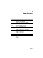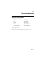
1
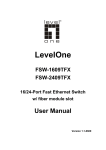
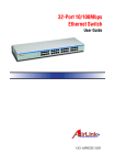
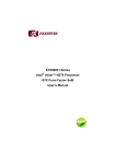
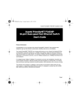
FriendlyNet 4000E Series
Fast Ethernet Switch
FS4002E/FS4004E
FS4008E/FS4016E
User’s Manual
Copyright Notice
Trademarks
Asanté Technologies and FriendlyNet are trademarks of Asanté Technologies, Inc. Ethernet is a registered
trademark of the Xerox Corporation. All brand names and products are trademarks or registered trademarks of their respective holders.
FCC Information
This device complies with part 15 of the FCC Rules. Operation is subject to the following two conditions:
(1) this device may not cause harmful interference and (2) this device must accept any interference received,
including interference that may cause undesired operation.
Operation of this equipment in a residential area is likely to cause interference, in which case, the user, at
his or her own risk and expense, will be required to correct the interference.
LIMITED LIFETIME WARRANTY
Subject to the limitations and exclusions below, Asanté warrants to the original end user purchaser that the
covered products will be free from defects in title, materials and manufacturing workmanship for as long as
you own them. This warranty excludes fans, power supplies and accessories. Asanté warrants that the fans
and power supplies will be free from defects in title, materials and manufacturing workmanship for one year
from date of purchase.
To take advantage of this warranty, you must contact Asanté for a return materials authorization (RMA)
number. The RMA number must be clearly written on the outside of the returned package. Product must
be sent to Asanté postage paid. In the event of a defect, Asanté will repair or replace defective product or
components with new, refurbished or equivalent product or components as deemed appropriate by Asanté.
The foregoing is your sole remedy, and Asanté's only obligation, with respect to any defect or non-conformity.
Asanté makes no warranty with respect to accessories (including but not limited to cables, brackets and fasteners) included with the covered product, nor to any discontinued product, i.e., product purchased more
than thirty days after Asanté has removed such product from its price list or discontinued shipments of such
product.
This warranty is exclusive and is limited to the original end user purchaser only. This warranty shall not
apply to secondhand products or to products that have been subjected to abuse, misuse, abnormal electrical
or environmental conditions, or any condition other than what can be considered normal use. ASANTÉ
MAKES NO OTHER WARRANTIES, EXPRESS, IMPLIED OR OTHERWISE, REGARDING THE
ASANTÉ PRODUCTS, EXCEPT TO THE EXTENT PROHIBITED BY APPLICABLE LAW, ALL
WARRANTIES OR CONDITIONS OF MERCHANTABILITY OR FITNESS FOR A PARTICULAR
PURPOSE ARE HEREBY DISCLAIMED. ASANTÉ’S LIABILITY ARISING FROM OR RELATING
TO THE PURCHASE, USE OR INABILITY TO USE THE PRODUCTS IS LIMITED TO A
REFUND OF THE PURCHASE PRICE PAID. IN NO EVENT WILL ASANTÉ BE LIABLE FOR
INDIRECT, SPECIAL, INCIDENTAL, OR CONSEQUENTIAL DAMAGES FOR THE BREACH
OF ANY EXPRESS OR IMPLIED WARRANTY, INCLUDING ECONOMIC LOSS, DAMAGE TO
PROPERTY AND, TO THE EXTENT PERMITTED BY LAW, DAMAGES FOR PERSONAL
INJURY, HOWEVER CAUSED AND ON ANY THEORY OF LIABILITY (INCLUDING NEGLIGENCE). THESE LIMITATIONS SHALL APPLY EVEN IF ASANTE HAS BEEN ADVISED OF
THE POSSIBILITY OF SUCH DAMAGES OR IF THIS WARRANTY IS FOUND TO FAIL OF ITS
ESSENTIAL PURPOSE.
Some jurisdictions do not allow the exclusion or limitation of incidental or consequential damages or limitations on how long an implied warranty lasts, so the above limitations or exclusions may not apply to you.
This warranty gives you specific legal rights, and you may have other rights, which vary from jurisdiction
to jurisdiction.
Table of Contents
Table of Contents ............................................ TOC-i
About This Manual ...................................................i
Chapter Contents ..........................................i
Document Conventions ................................ ii
Introduction .......................................................... 1-1
FriendlyNet Fast Ethernet Switch .................. 1-1
Features ......................................................... 1-2
Performance Features ................................... 1-3
Fast Ethernet and Switching Technology ...... 1-3
Fast Ethernet Technology ........................ 1-3
Switching Technology ............................... 1-4
Switch Supports Network Expansion ........ 1-4
Switch Acts as a Bridge Between Network
Segments ................................................ 1-4
Installation ........................................................... 2-1
Package Contents ......................................... 2-1
Components ................................................... 2-2
FS4002E ................................................... 2-2
FS4004E ................................................... 2-3
FS4008E ................................................... 2-4
FS4016E ................................................... 2-4
Cabling and Voltage Requirements ............... 2-5
Cabling Requirements .............................. 2-5
Voltage Requirements .............................. 2-6
Mounting Configurations ................................ 2-6
Desktop Mounting ..................................... 2-6
Page i
Wall Mounting the FS4002E, FS4004E,
and FS4008E ............................................ 2-7
Rack Mounting the FS4008E or FS4016E 2-8
Connecting Network Devices ......................... 2-9
Connecting a PC to the Switch ................. 2-9
Connecting a Hub or a Switch to the
Asanté Switch ......................................... 2-10
Connecting a Hub with no Uplink Port to
the Switch .............................................. 2-10
Powering on the Switch ................................ 2-11
FS4002E and FS4004E .......................... 2-11
FS4008E and FS4016E .......................... 2-11
LED Indicators ..................................................... 3-1
LED Indicators on the Switch ......................... 3-1
LED Indicators for Power On .................... 3-2
LED Indicators for Port Connections ......... 3-3
Link LED .............................................. 3-3
100Mbps Operation LED ..................... 3-3
FDP LEDs (FS4016E Only)................. 3-3
Activity LEDs ....................................... 3-4
Troubleshooting ............................................... A-1
Specifications ................................................... B-1
Technical Support ............................................ C-1
Contacting Technical Support .................. C-1
Page ii
About This Manual
This manual describes four models of the FriendlyNet Fast Ethernet FS4000E
Series Switches:
❑
FS4002E — two-port 10/100Mbps Fast Ethernet Switch
❑
FS4004E — four-port 10/100Mbps Fast Ethernet Switch
❑
FS4008E — eight-port 10/100Mbps Fast Ethernet Switch
❑
FS4016E — sixteen-port 10/100Mbps Fast Ethernet Switch
These models are similar in every respect except for the number of ports and
LED indicators (FS4016E only). Therefore, unless otherwise noted, all
information provided in this manual is applicable to all.
Chapter Contents
This manual is divided into the following chapters and appendices:
❑
Chapter 1, “Introduction,” describes the FriendlyNet FS4002E,
FS4004E, FS4008E and FriendlyNet FS4016E Fast Ethernet
Switches and their features
❑
Chapter 2, “Installation,” explains how to install, mount, and apply
power to the FriendlyNet Fast Ethernet Switches
❑
Chapter 3, “LED Indicators,” describes how to interpret the LEDs
on the FriendlyNet Fast Ethernet Switches’
❑
Appendix A, “Troubleshooting,” explains how to troubleshoot problems by monitoring the FriendlyNet Fast Ethernet Switches’ LEDs
❑
Appendix B, “Specifications,” describes the FriendlyNet Fast Ethernet Switches’ technical specifications
❑
Appendix C, “Technical Support” explains how to contact Asanté
Technical Support
Page i
Document Conventions
This manual uses the terms “Switch” (first letter upper case) to refer to the
FriendlyNet FS4002E, FS4004E, FS4008E or FS4016E 10/100Mbps Fast
Ethernet Switch, and “switch” (first letter lower case) to refer to all other
Ethernet switches.
This manual uses the following conventions to convey instructions and
information:
❑
Commands and key words are in boldface font.
◆
Note: Noteworthy information, which contains helpful
suggestions or references to other sections in the manual, is
in this format.
▲
Important! Significant information that calls attention to
important features or instructions is in this format.
Page ii
1
Introduction
This chapter introduces the Asanté FriendlyNet Fast Ethernet FS4000E Series
10/100Mbps Switches. It also provides an overview of Fast Ethernet and
switching technology.
FriendlyNet Fast Ethernet Switch
Thank you for purchasing an Asanté FriendlyNet FS4000E Series Switch. The
FriendlyNet FS4000E products are unmanaged 10/100 Fast Ethernet switches.
These switches are designed to address increasing network bandwidth needs and
to accommodate future network expansion.
FriendlyNet
FS4002E
2-port 10/100 Fast Ethernet Switch
1
1
2
or
2
Uplink
Power
10/100Mbps Ports
Figure 1-1 FriendlyNet FS4002E
FriendlyNet
FS4004E
4-port 10/100 Fast Ethernet Switch
1
2
3
1
4
2
3
or
4
Uplink
Power
10/100Mbps Ports
Figure 1-2 FriendlyNet FS4004E
FriendlyNet
FS4008E
8-port 10/100 Fast Ethernet Switch
1
2
3
4
5
6
7
1
8
2
3
4
5
6
7
8
or
Uplink
Power
Switched 10/100Mbps Ports
Figure 1-3 FriendlyNet FS4008E
FS4016E
FriendlyNet
16-port 10/100 Fast Ethernet Switch
2
4
6
8
10
12
14
16
1
3
5
7
9
11
13
15
or
Power
100 Mbps
FDP
Activity
Link
Uplink
1
2
3
4
5
6
7
8
9
10 11
12
13
14
15 16
Switched 10/100Mbps Ports
Figure 1-4
FriendlyNet FS4016E
Page 1-1
Introduction
Each Switch features full plug-and-play installation. Indicators include power,
link, 10/100Mbps, and activity LEDs for easy monitoring of Switch operation.
In addition, the FS4016E switch also features FDP (full- or half-duplex) LED
indicators, which provide a visual indication of duplex operation.
For network expansion, each Switch has an uplink port that makes it easy to
connect it to another Fast Ethernet switch or to the network backbone.
Features
The FriendlyNet FS4000E Series Switches have the following features:
❑
Compact size — designed for small to large workgroups in spacelimited areas; installs on desktop or wall (FS4002E/FS4004E/
FS4008E, optional wall-mount kit for the FS4016E), or installs in a
standard 19-inch equipment rack (FS4008E/FS4016E).
❑
Plug-and-play installation
❑
Connects from two to sixteen (depends on model) 10Base-T or
100Base-TX segments per switch
❑
Provides an uplink selector button for connecting to another network
device without using a crossover cable
❑
Automatic speed detection on all ports to determine network speed
❑
Full NWay auto-negotiation for half- or full-duplex operation on all
ports
❑
Asanté’s Intelligent Forwarding Technology chooses the fastest
packet forwarding method: fragment free or store-and-forward
❑
Asanté’s Efficient Data Flow Technology promotes smooth, predictable cell transfer which maximizes time sensitive data transmission
❑
Allows cascading from any port to any number of switches (limit of
seven chained switches in spanning tree enabled networks).
❑
Complies with IEEE 802.3 Ethernet/802.3u Fast Ethernet standard
❑
Works with Category 3 or 5 UTP (unshielded twisted-pair) cable
❑
Provides power, link, 10/100Mbps operation, and activity or data
LEDs to aid network diagnosis and simple management
❑
Ideal for deployment with multiple high-speed servers for dedicated
bandwidth (10Mbps or 100Mbps) workgroups, or as a segmentation
device for larger congested networks.
Page 1-2
Performance Features
Performance Features
The FriendlyNet FS4002E, FS4004E, FS4008E and FS4016E have the
following performance features:
❑
Asanté’s Intelligent Forwarding Technology feature provides automatic fragment free or store-and-forward switching, which ensures
data integrity with minimum latency
❑
Asanté’s unique EDF (Efficient Data Flow Technology) minimizes
communication delays between ports, which promotes maximum
efficiency for time-sensitive business applications such as video and
multimedia.
❑
NWay auto-negotiation on all ports automatically senses port speed
(10/100Mbps) and negotiates duplex mode (full-duplex or halfduplex)
❑
Data forwarding rate at 100% of wire-speed, or 148,800pps at
100Mbps, 14,880pps at 10Mbps for 64-byte packets
❑
Data filtering at 100% of wire-speed
❑
8K active MAC address entry table per device (self-learning)
❑
4 to 8MB (FS4008E/FS4016E) or 1 to 2MB (FS4002E/FS4004E)
packet buffer per device (dynamically allocated for each port)
Fast Ethernet and Switching Technology
This section provides a brief overview of Fast Ethernet switching technology.
Fast Ethernet Technology
Fast Ethernet, or 100Base-T, represents a non-disruptive, smooth evolution
from the current 10Base-T technology.
Fast Ethernet technology:
❑
Extends the 10Mbps Ethernet standard to transmit and receive data
at 100Mbps
❑
Maintains the CSMA/CD Ethernet protocol
❑
Allows for simple upgrades, since it is compatible with all other
10Mbps Ethernet environments
❑
Takes advantage of your company’s existing investment in hardware,
software and personnel training
Page 1-3
Introduction
Switching Technology
An Ethernet switch is a device that can direct network traffic among several
Ethernet and Fast Ethernet networks. A switch increases network capacity and
decreases network loading by making it possible for a LAN to be divided into
multiple, unique dedicated segments.
Switch Supports Network Expansion
In Fast Ethernet networks, a switch allows chaining of hubs beyond the “tworepeater limit.” A switch can be used to separate the network into different
collision domains, which allows expansion beyond the 205 meter diameter limit
for 100BASE-TX networks.
Asanté Switches support traditional 10Mbps Ethernet and 100Mbps Fast
Ethernet, and are ideal for bridging them without the need for a separate device.
Switch Acts as a Bridge Between Network Segments
A switch acts as a high-speed selective bridge between individual segments.
Traffic that needs to go from one segment to another is automatically forwarded
by a switch, without interfering with any other segments. This allows the total
network capacity to be multiplied while decreasing network loading.
To ensure network reliability, a switch monitors each of its ports for signal
quality. The switch automatically disconnects stations transmitting excessive
noise, then reconnects them when the problem is resolved. A switch also
automatically drops data packets that exceed the maximum allowable length.
This prevents a device from blocking the network by transmitting continuous
data streams or extra-long packets.
The Asanté switching engine supports automatic fragment free packet
forwarding. Fragment free switch mode allows the switch to make the fastest
possible switching decisions without forwarding runt packages on the network.
The switch automatically drops (or filters) illegally short packets known as
runts, which prevent bad packets from propagating across segments. Runts are
usually the result of packet collisions on a congested network.
The Asanté switching engine also supports store and forward switching. It will
automatically choose the safest and fastest method of switching if the source
and destination are at the same speed .I f the speeds are different, such as for a
10Mbps workstation connected to a 100Mbps server, the switch will buffer and
read the entire packet, perform a data validity check, then forward the packet at
the new speed. With Asanté Intelligent Forwarding your FriendlyNet Switch
will automatically pick the best and fastest switching method for you.
Page 1-4
2
Installation
This chapter explains how to install the FriendlyNet Fast Ethernet FS4000E
Series Switch Family. It contains the following sections:
❑
Package Contents
❑
FriendlyNet Fast Ethernet Switch Components
❑
Cabling and Voltage Requirements
❑
Mounting Configurations
❑
Connecting Network Devices
❑
Powering on the Switch
Package Contents
The FriendlyNet Fast Ethernet FS4000E Series Switches are shipped with the
following items:
❑
(1) FriendlyNet 2-port FS4002E, 4-port FS4004E, 8-port FS4008E
or 16-port FS4016E Fast Ethernet Switch
❑
(1) AC power cord for FS4008E or FS4016E
❑
(1) Receptacle-mount AC/DC converter for FS4002E or FS4004E)
❑
(4) Self-adhesive rubber feet
❑
(1) Wall-mount kit (FS4002E, FS4004E and FS4008E only) which
includes two pan-head #10x3/4 screws and two plastic screw anchors
❑
(1) Rack-mount kit (FS4008E and FS4016E only) which includes
two rack-mounting brackets and mounting screws
❑
(1) User’s Manual (this book)
Page 2-1
Installation
Components
This section describes the front- and back-panel layouts of the FS4000E Series
Switches. The only front panel contol on the FS4002E, FS4004E and FS4008E
Switches is the Uplink pushbutton switch, and the only control on the rear
panel is the Ports Half Duplex Full NWay DIP switch. These units have the
same LED indicator arrangement except for differences due to the number of
ports. LED indicators are described in detail in Chapter 3.
The FS4016E is similar to the other Switches. It has an uplink pushbutton
switch on the front panel but does not have any controls on the back panel. The
duplex/NWay function provided by the Ports Half Duplex Full NWay DIP
switch in the FS4002E/FS4004/FS4008 units is implemented automatically in
the FS4016E. T he function status is indicated by a row of FDP (full-duplex)
LEDs on the front panel.
The Uplink pushbutton switch is connected to a single port on each Switch.
In Normal position, the port associated with the switch operates like any other
port on the unit. When the Uplink pushbutton is in the depressed position, the
port associated with the switch becomes an uplink port and eliminates the need
for a crossover cable.
Cable tie points are provided on the back panel of the FS4002E and FS4004E
Switches and may be used to secure the power cord to the panel.
FS4002E
The front panel of the FS4002E contains two 10/100Mbps ports, one uplink
switch button, and LED indicators. See Figure 2-1.
Uplink Port (Selector)
FriendlyNet
FS4002E
2-port 10/100 Fast Ethernet Switch
1
2
1
2
or
Uplink
Power
10/100Mbps Ports
LEDs
Two 10/100 Ports
Figure 2-1 FriendlyNet FS4002E front panel
The back panel of the FS4002E contains a 12Vdc power connector, which uses
a 115Vac receptacle-mount (or “brick”) type dc power supply. It also contains a
Ports switch consisting of two DIP switches. The DIP switches set the mode of
operation for each port, either Half Duplex or Full NWay. See Figure 2-2 .
Page 2-2
Components
Port DIP Switches
Power Connector
12V DC
N/A N/A 1 2
Figure 2-2 FriendlyNet FS4002E back panel
◆
Note: The FS4002E does not have a power switch. The
FS4002E is automatically powered on as soon as the power
cord is connected between the FS4002E and a power outlet.
FS4004E
The front panel of the FS4004E contains four 10/100 Mbps ports, one uplink
switch button, and LED indicators. See Figure 2-3.
Uplink Port (Selector)
FriendlyNet
FS4004E
4-port 10/100 Fast Ethernet Switch
1
2
3
1
4
2
3
4
or
Uplink
Power
10/100Mbps Ports
Four 10/100 Ports
LEDs
Figure 2-3 FriendlyNet FS4004E front panel
The back panel of the FS4004E contains a 12Vdc power connector, which uses
a 115Vac receptacle-mount (or “brick”) type dc power supply. It also contains a
ports switch consisting of four DIP switches. The DIP switches set the mode of
operation for each port, either half-duplex or full NWay. See Figure 2-4.
Port DIP Switches
Power Connector
12Vdc
1 2 3 4
Figure 2-4 FriendlyNet FS4004E back panel
Page 2-3
Installation
◆
Note: The FS4004E does not have a power switch. The
FS4002E is automatically powered on as soon as the power
cord is connected to the FS4004E and to a power outlet.
FS4008E
The front panel of the FS4008E consists of eight 10/100 Mbps ports, one
uplink button switch, and LED indicators. See Figure 2-5.
Uplink Port (Selector)
FriendlyNet
FS4008E
8-port 10/100 Fast Ethernet Switch
1
2
3
4
5
6
7
8
1
2
3
4
5
6
7
8
or
Uplink
Power
Switched 10/100Mbps Ports
LEDs
Eight 10/100 Ports
Figure 2-5 FriendlyNet FS4008E front panel
The back panel of the FS4008E contains a100-240Vac power connector. It also
contains a Ports switch consisting of nine DIP switches. (One of the DIP
switches, marked N/A, is not used.) The DIP switches set the mode of
operation for each port, either Half Duplex or Full NWay.
AC Power Connector
1 2 3 4 5 6 7 8 N/A
115/230V AC Input
Port DIP Switches
Figure 2-6 FriendlyNet FS4008E back panel
◆
Note: The FS4008E does not have a power switch. The
FS4008E is automatically powered on as soon as the power
cord is connected to the FS4008E and to a power outlet.
FS4016E
The front panel of the FS4016E contains sixteen 10/100Mbps ports, one
uplink switch button, and LED indicators. See Figure 2-7.
Page 2-4
Cabling and Voltage Requirements
Uplink Port (Selector)
FS4016E
FriendlyNet
16-port 10/100 Fast Ethernet Switch
2
4
6
8
10
12
14
16
1
3
5
7
9
11
13
15
or
Power
100 Mbps
FDP
Activity
Link
Uplink
1
2
3
4
5
6
7
8
9
10 11
12
13
14
15 16
Switched 10/100Mbps Ports
Sixteen 10/100 Ports
Figure 2-7 FriendlyNet FS4016E front panel
The back panel of the FS4016E contains a 100-240 VAC power connector.
There are no other controls or indicators. See Figure 2-8.
AC Power Connector
AC Power
100-240V
Figure 2-8 FriendlyNet FS4016E back panel
◆
Note: The FS4016E does not have a power switch. The
FS4016E is automatically powered on as soon as the power
cord is connected between the FS4016E and a power outlet.
Cabling and Voltage Requirements
This section describes the cabling and voltage requirements of the Switches.
Cabling Requirements
100Base-TX requires the use of data-grade Category 5) UTP (unshielded
twisted-pair) cable. Category 3 wiring may be used for 10Base-T.
▲
Important! Some installations have Category 5 cabling but
do not have wall outlets and/or wiring closet punch-down
blocks that meet Category 5 requirements.
100Base-TX requires that all wiring and accessories meet
EIA/TIA 568B specifications for proper operation. When
wiring a 100Base-TX network, make sure that the entire
cable plant meets specifications.
Page 2-5
Installation
Voltage Requirements
Check the AC power line voltage used in your area. The AC power adapter
included with the FS4002E and FS4004E Switches must match the
utility power.
The FS4008E and FS4016E are equipped with an internal power supply. Power
sensing is automatic for all international utility power. There is no power switch
on either of these units, they are powered on when the power cord is connected
between the Switch and the power outlet.
Mounting Configurations
This section describes how to mount the Switch on a desktop or a wall. It also
explains how to install the Switch in an equipment rack.
Desktop Mounting
To mount the Switch on a desktop or shelf:
1
Attach the four rubber feet (supplied) to the bottom of
each corner on the Switch. See Figure 2-9.
FriendlyNet
1
2
3
4
5
6
7
8
8-port 10/100 Fast Ethernet
1
2
3
Switch
FS4008E
4
5
Power
6
7
8
or
Uplink
Switched 10/100Mbp
s Ports
Figure 2-9 Desktop mounting
2
Place the Switch on a flat, stable, horizontal desktop or
shelf.
Make sure you allow enough ventilation space between the
Switch and surrounding objects.
The Switch is ready for network connections.
Page 2-6
Mounting Configurations
Wall Mounting the FS4002E, FS4004E, and FS4008E
The FS4002E, FS4004E, and FS4008E come with a wall-mount kit. The kit
consists of screws and wall anchors.
▲
Important! The FS4016E cannot be wall-mounted without
the optional wall mount kit, part number 99-00486--07.
To mount the FS4002E, FS4004E, and FS4008E on a wall, consider the
following when selecting a site:
❑
Select a site that is free of obstructions from other equipment or
devices
❑
Place the Switch high enough to easily observe LED indicators and to
allow for easy power and cable access
❑
Decide how you want the orientation of the front panel.
To mount the FS4002E, FS4004E, or FS4008E on a wall:
1
2
Measure the screw holes on the bottom of the Switch.
▲
Important! Drill the holes only to the depth of the screw’s
length. If the holes are too deep, the mount may not be
secure.
3
Insert the plastic anchors (supplied) into the drilled holes
and gently tap them in with a hammer.
4
Insert and turn the screws (supplied) into the plastic
anchors, leaving a small portion of the screws sticking out.
▲
Important! If the screw head is too high and the unit stands
too far off the wall, accidental pressure could cause screw
heads to press into the circuit board, and result in damage.
5
Lift the Switch and align the slots on the bottom of the
Switch with the screw anchors.
6
Gently slide the Switch onto the screws.
Drill two holes into the wall equalling the same distance as
measured in step 1.
The Switch wall mounting is complete. The Switch is ready
for network connections.
Page 2-7
Installation
Rack Mounting the FS4008E or FS4016E
The FS4008E and FS4016E come with a rack-mounting kit.
▲
Important! The FS4002E and FS4004E cannot be
,
installed in an equipment rack.
The FS4008E or FS4016E can be mounted in a standard 19-inch equipment
rack. This rack can be placed in a wiring closet with other equipment.
To install the Switch in an equipment rack:
1
Attach the two mounting brackets (supplied) on each side
of the chassis. See Figure 2-10.
FriendlyNet
1
2
3
4
5
6
7
8-port 10/100 Fast Ethernet
8
1
2
Switch
3
FS4008E
4
5
6
7
8
or
Power
Uplink
Switched 10/100Mbp
s Ports
Rack-mount bracket
Figure 2-10 Attaching mounting brackets to the FS4008E
2
Mount the Switch in the equipment rack by screwing the
mounting brackets to the equipment rack. See Figure 2-11.
FriendlyNet
1
2
3
4
5
6
7
8
8-port 10/100 Fast Ethernet
1
2
3
Switch
FS4008E
4
5
Power
6
7
8
or
Uplink
Switched 10/100Mbp
s Ports
Figure 2-11 Mounting the FS4008E in an equipment rack
The rack mounting is complete. The Switch is ready for
network connections.
Page 2-8
Connecting Network Devices
Connecting Network Devices
Before you connect network devices to the Switch, review the following
guidelines:
❑
Make sure the network cable length is less than 100 meters (Category
5 and up)
◆
Note: Category 3 is acceptable for 10Base-T
❑
Use a straight-through twisted pair cable or a crossover cable when
appropriate for either uplink or standard data ports
❑
When connecting two switches together (cascading switches), make
sure that the link between them is no longer than 100 meters
❑
Network cable segments can be connected to, or disconnected from,
the Switch while the Switch’s power is on
Connecting a PC to the Switch
❑
Use a four-pair Category 5 UTP straight-through cable with RJ-45
connectors
❑
Connect the PC to any of the Switch’s ports. See Figure 2-12
FriendlyNet
FS4008E
8-port 10/100 Fast Ethernet Switch
1
2
3
4
5
6
7
8
1
2
3
4
5
6
7
8
or
Uplink
Power
Switched 10/100Mbps Ports
Straight-through network cable
Figure 2-12 Connecting a PC to the Switch
Page 2-9
Installation
Connecting a Hub or a Switch to the Asanté Switch
❑
Use a two-pair Category 5 UTP straight-through cable with RJ-45
connectors
❑
Connect the hub’s uplink port to any of the Switch’s ports. See
Figure 2-13
FS4008E
FriendlyNet
FS4008E
8-port 10/100 Fast Ethernet Switch
1
2
3
4
5
6
7
1
8
2
3
4
5
6
7
8
or
Uplink
Power
Switched 10/100Mbps Ports
Straight-through network cable
Hub
straight-through cable
FH8DS
FriendlyNet
Stackable 8-port Dual Speed Ethernet Hub
Switched 10/100Mbps Ports
100Mbps
Partition
Power
100Mbps
Link/Receive
1
2
3
4
5
7
8
1
2
3
4
5
6
7
or
8
Uplink
Hub’s uplink port
Figure 2-13 Connecting a hub to the Switch
Connecting a Hub with no Uplink Port to the Switch
If a hub is not equipped with an uplink port, connection can be made using
straight-through cable, as outlined below. The uplink button must be
depressed. See Figure 2-14
FS4008E Switch
FriendlyNet
FS4008E
8-port 10/100 Fast Ethernet Switch
1
2
3
4
5
6
7
1
8
2
3
4
5
6
7
8
or
Uplink
Power
Switched 10/100Mbps Ports
Hub
FH8DS
FriendlyNet
Stackable 8-port Dual Speed Ethernet Hub
Switched 10/100Mbps Ports
100Mbps
Partition
Power
100Mbps
Link/Receive
1
2
3
4
5
7
8
1
2
3
4
5
6
7
Straight-through network cable
Figure 2-14 Connecting a hub without an uplink port to the Switch
Page 2-10
Powering on the Switch
Powering on the Switch
This section describes how to apply power to the FriendlyNet FS4000E Series
Switches.
◆
Note: This applies to the Uplink Port after powering on the
Switch. If you are unsure of your cable type (straightthrough or crossover) and the Link LED associated with
the port is not on, try pressing the Uplink button again.
FS4002E and FS4004E
The FS4002E/FS4004E Switches may be turned on with (or without) LAN
segment cables connected. To power on the Switch:
1
Connect one end of the power cord (supplied) into the
12Vdc power connector on the back panel of the Switch.
▲
Important: Make sure the power supply that was packaged
with your FriendlyNet Switch is matched with the line voltage used in your area.
2
Plug the 12Vdc power supply into an AC power outlet.
◆
Note: There is no power switch on the FS4002E or
FS4004E. These switches are automatically powered on as
soon as the power cord is connected between the Switch and
the power outlet.
FS4008E and FS4016E
The FS4008E/FS4016E may be turned on with (or without) LAN segment
cables connected. To power on the Switch:
1
Connect one end of the power cord (supplied) into the
AC power connector on the back panel of the Switch.
◆
Note: The FS4008E and FS4016E are equipped with an
internal power supply. Power sensing is automatic for all
international utility power.
◆
Note: There is no power switch on the FS4008E or
FS40016E. These switches are automatically powered on as
soon as the power cord is connected between the Switch and
the power outlet.
2
Connect the power cord to a local power source outlet.
Page 2-11
Installation
Page 2-12
3
LED Indicators
This chapter explains how to interpret the front panel LED indicators on the
FriendlyNet Fast Ethernet FS4000E Series Switches.
LED Indicators on the Switch
The LEDs on the Switch are used to facilitate monitoring and troubleshooting.
With the exception of the Power LED, all front panel LEDs are used to monitor
the status of each port. There are no LEDs on the rear panel.
These LEDs are:
❑
Power
❑
Link
❑
100Mbps
❑
Activity
❑
FDP (FS4016E only)
The front panel LEDs for the FS4000E Series Switches are shown in
Figures 3-1 through Figure 3-4.
1
2
Power
Link
100Mbps
Activity
Power
Figure 3-1 FS4002E LEDs
Page 3-1
LED Indicators
1
2
3
4
Link
100Mbps
Activity
Power
Power
Figure 3-2 FS4004E LEDs
1
2
3
4
5
6
7
8
Link
100Mbps
Activity
Power
Power
Figure 3-3 FS4008E LEDs
Power
100Mbps
FDP
Activity
Link
Power
100 Mbps
FDP
Activity
Link
1
2
3
4
5
6
7
8
9
10
11
12
13
14
15 16
Figure 3-4 FS4016E LEDs
LED Indicators for Power On
After power is turned on the LED indicators should respond as follows:
❑
All LED indicators blink momentarily. This represents a system reset.
❑
The Activity LEDs blink from slow to steady as traffic increases.
❑
The power LED indicator lights and remains ON. If this indicator is
not lit, check to make sure that the AC power connector (DC adapter
for FS4002E/FS4004E) is properly connected in the socket.
Page 3-2
LED Indicators on the Switch
LED Indicators for Port Connections
Link LED
The green Link LED indicates when a device is detected on the other end of the
port
Table 3-1 describes the possible status indications of the Link LEDs.
Table 3-1
State
Link LED status indicators
Status
On
Normal data/link pulse reception
Off
No twisted-pair cable connected
Wrong cable type, check for crossover or straight-through
Link pulse disabled at other end
No power to the switch, twisted-pair connection faulty
Non-10/100 TX device at other end
Twisted-pair cable exceeds recommended length
100Mbps Operation LED
The yellow 100Mbps LED indicates whether 10Mbps or 100Mbps device is
connected to the port.
Table 3-2 describes the possible status indications of the 100Mbps LED.
Table 3-2
State
100Mbps LED Status Indicators
Status
On
A 100Mbps device is connected to a port or the uplink port
Off
A 10Mbps device is connected to a port or the uplink port
FDP LEDs (FS4016E Only)
The green FDP LED indicates port operation in full- or half-duplex mode.
Table 3-3 describes the possible status indications of the FDP LEDs.
Table 3-3
State
FDP LED Status Indicators
Status
On
Port is in full-duplex mode
Off
Port is in half-duplex mode
Page 3-3
LED Indicators
Activity LEDs
The green Activity LEDs indicate transmit/receive activity.
Table 3-4 describes the possible status indications of the Activity LEDs.
Table 3-4
State
Activity LED Status Indicators
Status
On
Data is transmitting or receiving on this port.
Off
No data activity on this port.
Page 3-4
A
Troubleshooting
Table A-1 describes how to troubleshoot problems with your network and/or
the Switch by monitoring the Switch’s LEDs.
Table A-1
Troubleshooting
Problem
Action
Power LED is off
Make sure the power adapter is connected to the power outlet and is properly inserted into the power connector on the switch.
Determine if the power outlet is functional by plugging another device
into the receptacle.
Link LED is off
Make sure that both switch and device on the other end are powered on.
Make sure the proper cabling is used between the device and the Switch
(refer to the cable guidelines specified in Chapter 2).
Make sure the correct cable is connected between the Switch and the network device.
Push Uplink button again
Make sure the cable does not exceed 100 meters.
Slow performance
Make sure the duplex mode on both ends of the link connection is configured to the same mode (half- or full-duplex).
If your adapter card supports NWay auto-negotiation, make sure the
driver also supports full-duplex mode.
Page A-1
Page A-2
B
Specifications
FS4000E Series Specifications
Standards
IEEE 802.3 10Base-T Ethernet
IEEE 802.3u 100Base-TX Fast Ethernet
IEEE 802.3 MAC layer frame size: 64 to 1518 bytes
Protocol
CSMA/CD
Data Transfer
Rate
Ethernet/Fast Ethernet
10Mbps (half-duplex)/100Mbps (half-duplex)
20Mbps (full-duplex)/200Mbps (full-duplex)
Topology
Star
Network Cables
10Base-T: 4-pair UTP Category 3 (100m maximum)
100Base-TX: 4-pair UTP Category 5 (100m maximum)
Number of Ports
FS4002E:
FS4004E:
FS4008E:
FS4016E:
Connectors
RJ-45 (10Base-T and 100Base-TX)
LEDs
Power
Link
100Mbps
Activity
FDP (FS4016E only)
2 x 10/100Mbps ports
4 x 10/100Mbps ports
8 x 10/100Mbps ports
16 x 10/100Mbps ports
Page B-1
FS4000E Series Physical and Environmental Specifications
AC Inputs
100 - 240VAC, 50/60 Hz (internal universal power supply)
Power
Consumption
40 watts maximum
Operating
Temperature
32° – 122° F (0° – 40° C)
Storage Temperature
-22° – 140° F (-30° – 60° C)
Humidity
5% to 95% non-condensing
Dimensions
FS4002E:
FS4004E:
FS4008E:
FS4016E:
7.5 in wide x 5 in deep x 1.5 in high
7.5 in wide x 5 in deep x 1.5 in high
13 in wide x 9 in deep x 1.75 in high
13 in wide x 9 in deep x 1.75 in high
Weight (Shipping)
FS4002E:
FS4004E:
FS4008E:
FS4016E:
2.2 lbs (1 Kg)
2.2 lbs (1 Kg)
5.2 lbs (2.4 Kg)
5.2 lbs (2.4 Kg)
EMI
FCC Class A, CE Mark, VCCI Class I
Safety
UL (UL 1950), CSA (CSA950)
FS4000E Series Performance Specifications
Transmission
Method
Store-and-forward
RAM Buffer
FS4002E: 1MB per device,
FS4004E: 2MB per device
FS4008E: 4MB per device,
FS4016E: 8MB per device
Filtering
Address Table
8K entries per device
Packet Filtering/
Forwarding Rate
148,800pps per port (for 100Mbps max)
Page B-2
C
Technical Support
Contacting Technical Support
To contact Asanté Technical Support:
Telephone
(800) 622-7464
Fax
(801) 566-3787
Fax-Back
(800) 741-8607
E-mail
[email protected]
World Wide Web Site
http://www.asante.com
Technical Support Hours
6:00 a.m. to 5:00 p.m. Pacific Standard Time USA, Monday - Friday.
Page C-1
ASANTÉ TECHNOLOGIES, INC., 821 FOX LANE, SAN JOSE, CA 95131
PHONE: 800.622.7464 • FAX: 801.566.3787 • e-mail address: [email protected] •
World Wide Web site: http://www.asante.com
©1998 Asanté Technologies Inc., Asanté is a trademark of Asanté Technologies, Inc.
All brand names and products are trademarks or registered trademarks of their respective holders.
May 1998
Part Number 06-00432-00