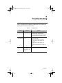
1
SHBBook Page 1 Wednesday, March 3, 1999 8:03 PM
NetStacker II
Dual Speed Stackable Hub
User’s Manual
SHBBook Page 2 Wednesday, March 3, 1999 8:03 PM
Copyright Notice
Trademarks
Asanté Technologies and FriendlyNET are trademarks of Asanté Technologies, Inc. Ethernet is a registered
trademark of the Xerox Corporation. A ll brand names and products are trademarks or registered trademarks of their respective holders.
FCC Information
This device complies with part 15 of the FCC Rules. Operation is subject to the following two conditions:
(1) this device may not cause harmful interference and (2) this device must accept any interference received,
including interference that may cause undesired operation.
Operation of this equipment in a residential area is likely to cause interference, in which case, the user, at
his or her own risk and expense, will be required to correct the interference.
FIVE YEAR LIMITED WARRANTY
Subject to the limitations and exclusions below, Asanté warrants to the original end user purchaser that the
covered products will be free from defects in materials and manufacturing workmanship for a period of 5
years from date of purchase. This warranty excludes fans, power supplies and accessories. Asanté warrants
that the fans and power supplies contained in covered products will be free from defects in materials and
manufacturing workmanship for one year from date of purchase.
To take advantage of this warranty, you must:
(1)contact Asanté for a return materials authorization (RMA) number. The RMA number must be clearly
written on the outside of the returned package.(2)Product must be sent to Asanté postage paid. (3)Provide
Asanté with proof of the original date of purchase.
During the warranty period, Asanté’s sole obligation, and your exclusive remedy is that Asanté will repair or
replace defective product or components with new, refurbished or equivalent product or components as
deemed appropriate by Asanté in its sole discretion. The foregoing is your exclusive remedy, and Asanté’s
only warranty obligation.
Asanté makes no warranty with respect to accessories (including but not limited to cables, brackets and fasteners) included with the covered product. No warranty is made as to any discontinued product, which is
defined as product purchased more than thirty days after Asanté has removed such product from its price
list or discontinued shipments of such product.
This warranty is exclusive and is limited to the original end-user purchaser only. This warranty shall not
apply to secondhand products or to products that have been modified or subjected to abuse, misuse, abnormal electrical or environmental conditions, or any condition other than what can be considered normal
use.
ASANTÉ MAKES NO OTHER WARRANTIES, EXPRESS, IMPLIED OR OTHERWISE, REGARDING
THE ASANTÉ PRODUCTS. EXCEPT TO THE EXTENT SPECIFICALLY MANDATED BY APPLICABLE
LAW, ALL WARRANTIES OR CONDITIONS OF MERCHANTABILITY OR FITNESS FOR A PARTICULAR PURPOSE ARE HEREBY DISCLAIMED.
ASANTÉ’S LIABILITY ARISING FROM OR RELATING TO THE PURCHASE, USE OR INABILITY TO
USE THE PRODUCTS IS LIMITED TO REPAIR, REPLACEMENT OR A REFUND OF THE PURCHASE
PRICE PAID. IN NO EVENT SHALL ASANTÉ BE LIABLE FOR INDIRECT, SPECIAL, INCIDENTAL, OR
CONSEQUENTIAL DAMAGES OF ANY KIND OR CHARACTER FOR THE BREACH OF ANY
EXPRESS OR IMPLIED WARRANTY, INCLUDING ECONOMIC LOSS, DAMAGE TO PROPERTY
AND, TO THE EXTENT PERMITTED BY LAW, DAMAGES FOR PERSONAL INJURY, HOWEVER
CAUSED AND ON ANY THEORY OF LIABILITY (INCLUDING NEGLIGENCE). THESE LIMITATIONS SHALL APPLY EVEN IF ASANTÉ HAS BEEN ADVISED OF THE POSSIBILITY OF SUCH DAMAGES OR IF THIS WARRANTY OR ANY CLAUSE HEREIN IS FOUND TO FAIL OF ITS ESSENTIAL
PURPOSE.
YOU MUST COMPLETE AND RETURN THE WARRANTY REGISTRATION CARD WITHIN 30 DAYS
OF YOUR PURCHASE TO PRESERVE WARRANTY BENEFITS.
Some jurisdictions do not allow the exclusion or limitation of incidental or consequential damages or limitations on how long an implied warranty
lasts, so the above limitations or exclusions may not apply to you. This warranty gives you specific legal rights, and you may have other rights, which
vary from jurisdiction to jurisdiction.
SHBBook Page i Wednesday, March 3, 1999 8:03 PM
Table of Contents
About This Manual ................................................. iii
Chapter Contents .............................................. iii
Document Conventions ..................................... iv
Important Safety Instructions ............................ iv
Introduction .......................................................... 1-1
Package Contents ......................................... 1-1
The NetStacker II Hubs .................................. 1-1
Performance Features ................................... 1-3
Installation ........................................................... 2-1
Components ................................................... 2-1
Front Panels of 12 Port and 24 Port Hubs 2-1
Rear Panels of 12 Port and 24 Port Hubs 2-3
Cabling and Voltage Requirements ............... 2-4
Cabling Requirements .............................. 2-4
Voltage Requirements .............................. 2-4
Placement and Mounting ............................... 2-5
Hub Location ............................................ 2-5
Desktop Mounting ..................................... 2-5
Rack Mounting .......................................... 2-5
Connecting Network Devices ......................... 2-6
Connecting Workstations or Servers ........ 2-6
Connecting to Another Hub ...................... 2-7
Stacking Hubs ........................................ 2-10
Powering on the Hub ................................... 2-11
Page i
SHBBook Page ii Wednesday, March 3, 1999 8:03 PM
LED Indicators ..................................................... 3-1
Power LED ..................................................... 3-2
Collision Indicator LEDs ................................. 3-2
Hub ID Number LEDs ..................................... 3-3
Port Link Activity Indicator LEDs .................... 3-3
10Mbps Link Activity LEDs ....................... 3-3
100Mbps Link Activity LEDs ..................... 3-3
Troubleshooting ...................................................A-1
Specifications .......................................................B-1
Technical Support ............................................... C-1
Contacting Technical Support .................. C-1
Page ii
SHBBook Page iii Wednesday, March 3, 1999 8:03 PM
About This Manual
This manual describes the NetStacker II dual speed stackable hubs. The manual
focuses on the following two models:
❑
12-port 10/100Mbps managed stackable hub
❑
24-port 10/100Mbps managed stackable hub
Unless otherwise noted, all information provided in this manual is applicable to
both units.
Chapter Contents
This manual is divided into the following chapters and appendices:
❑
Chapter 1, “Introduction,” provides an overview of the NetStacker II
dual speed stackable hubs and their features
❑
Chapter 2, “Installation,” describes the components and explains
how to install, mount, and apply power to the NetStacker II dual
speed stackable hubs
❑
Chapter 3, “LED Indicators,” describes how to interpret the LEDs
on the NetStacker II dual speed stackable hubs
❑
Appendix A, “Troubleshooting,” explains how to solve problems by
monitoring the LEDs on the NetStacker II dual speed stackable hubs
❑
Appendix B, “Specifications,” describes the NetStacker II dual speed
stackable hubs’ technical specifications
❑
Appendix C, “Technical Support” explains how to contact Asanté
Technical Support
Page iii
SHBBook Page iv Wednesday, March 3, 1999 8:03 PM
Document Conventions
This manual uses the term “NetStacker II” to refer to the 12 port and 24 port
dual speed hubs, and “hub” to refer to all other Ethernet hubs.
This manual uses the following conventions to convey instructions and
information:
◆
Note: Noteworthy information, which contains helpful
suggestions or references to other sections in the manual, is
in this format.
▲
Important! Significant information that calls attention to
important features or instructions is in this format.
Important Safety Instructions
1. Read all of these instructions.
2. Save these instructions for later use.
3. Follow all warnings and instructions marked on the product.
4. Unplug this product from the wall outlet before cleaning. Do not use liquid
cleaners or aerosol cleaners. Use a damp cloth for cleaning.
5. Do not use this product near water.
6. Do not place this product on an unstable cart, stand, or table. The product
may fall, causing serious damage to the product.
7. The openings should never be blocked by placing the product on a bed, sofa,
rug, or other similar surface. This product should never be placed near or over a
radiator or heat register. This product should not be placed in a built-in
installation unless proper ventilation is provided.
8. This product should be operated from the type of power source indicated on
the marking label. If you are not sure of the type of power available, consult
your dealer or local power company.
9. This product is equipped with a three-wire grounding type plug, a plug
having a third (grounding) pin. This plug will only fit into a grounding type
power outlet. This is a safety feature. If you are unable to insert the plug into
the outlet, contact your electrician to replace your obsolete outlet. Do not
defeat the purpose of the grounding type plug.
10. Do not allow anything to rest on the power cord. Do not locate this product
where persons will walk on the cord.
Page iv
SHBBook Page v Wednesday, March 3, 1999 8:03 PM
About This Manual
11. If an extension cord is used with this product, make sure that the total
ampere ratings on the products connected to the extension cord do not exceed
the extension cord ampere rating. Also make sure that the total of all products
plugged into the wall outlet does not exceed 15 amperes.
12. Never push objects of any kind into this product through cabinet slots as
they may touch dangerous voltage points or short out parts that could result in
a risk of fire or electric shock. Never spill liquid of any kind on the product.
13. Do not attempt to service this product yourself, as opening or removing
covers may expose you to dangerous voltage points or other risks. Refer all
servicing to service personnel.
Page -v
SHBBook Page vi Wednesday, March 3, 1999 8:03 PM
Page vi
SHBBook Page 1 Wednesday, March 3, 1999 8:03 PM
1
Introduction
This chapter introduces the Asanté NetStacker II 12 port and 24 port dual
speed stackable hubs and provides an overview of basic hub technology. The
chapter is made up of the following sections:
❑
Package Contents
❑
The NetStacker II Hubs
❑
Performance Features
❑
Network Concepts
Package Contents
The package contains the following items:
❑
(1) NetStacker II 12 port hub, or NetStacker II 24 port hub
❑
(1) AC power cord
❑
(4) Self-adhesive rubber feet
❑
(1) Rack-mount kit, which includes two rack-mounting brackets and
mounting screws
❑
User’s Manual (this book)
The NetStacker II Hubs
Thank you for purchasing an Asanté NetStacker II 12 port or 24 port hub. The
NetStacker II products are unmanaged dual speed stackable hubs which provide
a compact, flexible solution for medium to large workgroups and small office
LANS. These 12-port and 24-port hubs comply fully with IEEE802.3 and
IEEE802.3u standards.
Both the 12-port and 24-port hubs can be upgraded easily to managed hubs by
addition of an optional plug-in management module. This module slides into a
slot on the back panel of the hub. You do not need to purchase another hub to
gain full management capabilities - you can convert your unmanaged hub in a
matter of minutes.
Page 1-1
SHBBook Page 2 Wednesday, March 3, 1999 8:03 PM
Introduction
The NetStacker II 12 port unmanaged hub provides 12 twisted pair ports. The
24 port managed hub provides 24 twisted pair ports. In addition, both hubs
offer an expansion slot for a 100Base-FX interface so the user can slide a fiberoptic module into the rear panel. A slot for a 100Base-FX interface is also
provided on the front panel, for use when the management module has been
installed in the rear panel slot.
Both hubs automatically detect the speed (10Mbps or 100Mbps) of the devices
they are connected to. For additional expansion, each hub provides an Uplink
push-button for the 12th port, which can be cascaded to another hub by means
of straight through cable.
The NetStacker II hubs can be stacked up to 8 units high and connected by
means of the “Stack Connection In” and “Stack Connection Out” ports on the
rear panel. In addition, one of the hubs in the stack may be equipped with a
slide-in management module. The entire stack requires only one managed hub
for all of the stacked devices to be managed. Each dual speed hub has its own
ID, which is auto-detected and auto-configured. You do not have to configure
the hub ID yourself.
Either model hub can be placed on a tabletop or rack mounted. With
unmatched flexibility, the hubs ensure operation in any LAN environment,
regardless of size. The hubs provide the solutions that users require for their
complex networks.
Stackable Dual-Speed Hub
1
2
3
4
5
6
7
Hub ID Number
Uplink
COL
100M
Uplink
100Mbps
Normal
Power
10M
10Mbps
1
2
3
4
5
6
7
8
9
10
NS2012
NetStacker II
8
11
MII
Module
Slot
12
1
2
3
4
5
6
7
8
9
10
11
12
Figure 1-1 NetStacker II 12 port hub front panel
13
1
2
3
4
5
6
7
8
13
14
15
16
17
18
19
20
14
15
16
17
18
19
20
21
22
23
24
Stackable Dual-Speed Hub
NS2024
NetStacker II
Hub ID Number
100Mbps
10Mbps
21
22
23
Uplink
24
COL
100M
Uplink
100Mbps
Normal
Power
10M
10Mbps
1
2
3
4
5
6
7
8
9
10
11
12
1
2
3
4
5
6
7
8
9
10
11
12
Figure 1-2 NetStacker II 24 port hub front panel
Page 1-2
MII
Module
Slot
SHBBook Page 3 Wednesday, March 3, 1999 8:03 PM
Performance Features
Each hub features full plug-and-play installation. LED indicators include power
status, port link activity status, collision detection, and hub identification, for
easy monitoring of hub operation.
Performance Features
The NetStacker II dual speed stackable hubs offer the following features:
❑
Full compliance with the IEEE802.3 and IEEE802.3u Ethernet standards
❑
12 or 24 10/100Mbps auto-sensing ports
❑
Both 12-port and 24-port hubs stackable up to eight units
❑
Up to eight 12-port or 24-port hubs stackable with management by
means of a single slide-in management module added to one hub
❑
Both models accept optional slide-in fiber optic module
❑
Global LEDs: power indicator, 10Mbps collision detection,
100Mbps collision detection, and 8 hub identification indicators
❑
Port LEDs: link activity LED for both 10Mbps and 100Mbps
❑
Automatic partitioning of faulty ports
❑
Segmented hub to reduce collisions
❑
19 inch rack-mountable size
❑
CE mark certification
❑
Internal power that supports universal input voltage
Page 1-3
SHBBook Page 4 Wednesday, March 3, 1999 8:03 PM
Introduction
Page 1-4
SHBBook Page 1 Wednesday, March 3, 1999 8:03 PM
2
Installation
This chapter describes the components and explains how to install, mount, and
apply power to your NetStacker II dual speed hub. It contains the following
sections:
❑
Components
❑
Cabling and Voltage Requirements
❑
Placement and Mounting
❑
Connecting Network Devices
❑
Powering on the Hub
Components
This section describes the front and back panel layouts of the NetStacker II dual
speed hubs.
Front Panels of the 12 Port and 24 Port Hubs
The front panel of the 12 port hub displays:
❑
Twelve dual speed (UTP) Ethernet ports
❑
One uplink switch button
❑
LED indicators.
These features are shown in Figure 2-1.
Stackable Dual-Speed Hub
1
2
3
4
5
6
7
Hub ID Number
Uplink
100M
Uplink
100Mbps
Normal
Power
10M
10Mbps
1
2
3
4
5
6
7
8
9
10
NS2012
NetStacker II
8
COL
11
MII
Module
Slot
12
1
2
3
4
5
6
7
8
9
10
11
12
Figure 2-1 NetStacker II 12 port front panel
Page 2-1
SHBBook Page 2 Wednesday, March 3, 1999 8:03 PM
Installation
The front panel of the 24 port hub displays:
❑
Twenty-four dual speed (UTP) Ethernet ports
❑
One uplink switch button
❑
LED indicators.
These features are shown in Figure 2-2.
13
14
15
16
17
18
19
20
21
22
23
24
Stackable Dual-Speed Hub
NS2024
NetStacker II
1
2
3
4
5
6
7
8
13
14
15
16
17
18
19
20
21
22
23
24
1
2
3
4
5
6
7
8
9
10
11
12
Hub ID Number
100Mbps
10Mbps
Uplink
COL
100M
Uplink
100Mbps
Normal
Power
10M
10Mbps
1
2
3
4
5
6
7
8
9
10
11
MII
Module
Slot
12
Figure 2-2 NetStacker II 24 port front panel
LED Indicators
The front panels of the NetStacker II dual speed hubs display LED indicators,
as shown in Figure 2-3. The LED nomenclature, color, and function are as
follows:
❑
Power (green): Illuminates when AC power is applied to the hub.
❑
Collision “COL” (amber): A collision occurs when two or more stations in the Ethernet network attempt to transmit data at the same
time. The LED flashes to indicate a collision while the stations retransmit. There is one LED for 10Mbps and one for 100Mbps.
❑
Hub ID Number (green): Indicates the ID of the hub if it is part of a
stack; this identifying number is auto-configured, from one to eight.
❑
Link Activity “100Mbps/10Mbps” (green): Indicates that a device is
connected to the port number, and that either a 10Mbps (lower
LED) or 100Mbps (upper LED) link is detected. If the link is
detected, the LED turns on. If data is transmitting, the LED blinks.
Page 2-2
SHBBook Page 3 Wednesday, March 3, 1999 8:03 PM
Components
Hub ID
1
2
3
4
5
6
7
NetStacker II
8
Hub ID Number
COL
100M
Power
100Mbps
10M
100 Mbps
10Mbps
1
2
3
4
5
6
7
9
8
10
11
12
10 Mbps
Power
Collision
Figure 2-3 LED Indicators on 12 port hub
Rear Panels of the 12 Port and 24 Port Hubs
The rear panels of the 12 port and 24 port hubs both display:
❑
Management Module Slot; can also be used for optional 100Base FX
slide-in module that allows connection to fiber optic network media
❑
Stack Connection In and Stack Connection Out: Used to join the
hubs in a stack with stacking cables (one provided per hub). Up to
eight hubs may be connected together within a collision domain.
❑
Fan vents
❑
AC Power socket
❑
Power switch
These features are shown in Figure 2-4.
Stack Connection In
On
Management Module Slot
Stack Connection Out
100–240Vac
Off
Figure 2-4 NetStacker II rear panel
Page 2-3
SHBBook Page 4 Wednesday, March 3, 1999 8:03 PM
Installation
Cabling and Voltage Requirements
This section describes the cabling and voltage requirements for the
NetStacker II 12 port and 24 port hubs.
◆
Note: You may connect network cable segments to the hub
or disconnect them while the power is on. Plugging in or
removing cables while your hub is running will not interrupt the traffic or disrupt the operation of the hub.
Cabling Requirements
The cabling for connections to the NetStacker II hubs must meet or exceed the
following standards:
10Base-T
10Base-T transmission connection requires UTP (Unshielded Twisted Pair)
Category 3 cables, not to exceed 100 meters in length.
100Base-TX
100Base-TX transmission requires UTP (Unshielded Twisted Pair) Category 5
cables, not to exceed 100 meters in length. 100Base-TX requires that all wiring
and accessories meet EIA/TIA 568B specifications for proper operation. When
wiring a 100Base-TX network, make sure that the entire cable plant meets these
specifications.
▲
Important: Some installations have UTP Category 5
cabling but do not have wall outlets and/or wiring closet
punchdown blocks that meet Category 5 requirements.
100Base-FX
100Base-FX transmission requires 62.5/125 micron graded-index multimode
fiber-optic cable with an SC connector. For details on inserting a 100Base-FX
module, see “Adding Fiber Optic Connectivity via MII” on page 11 in this
chapter.
Voltage Requirements
Voltage requirements are the same for both hubs: 100 to 240VAC, at 50 to
60Hz, with a 1.2A maximum.
▲
Page 2-4
Important: Check the AC power line voltage used in your
area.
SHBBook Page 5 Wednesday, March 3, 1999 8:03 PM
Placement and Mounting
Placement and Mounting
This section describes how to mount the NetStacker II on a desktop or shelf.
Hub Location
The location chosen for the NetStacker II hub should be less than 100 meters
from servers, workstations, and other devices.
▲
Important: Category 5 cables are environment-sensitive.
Make sure that the cable route is not too close to electromagnetic noise sources such as power lines or fluorescent
lights.
Desktop Mounting
To place the hub on a desktop or shelf:
1
Attach the four rubber feet (supplied) to the bottom of
each corner on the hub. See Figure 2-5.
Stackable Dual-Speed Hub
1
2
3
4
5
6
7
Hub ID Number
Uplink
Uplink
100Mbps
Normal
Power
10M
10Mbps
1
2
3
4
5
6
7
8
9
10
NS2012
NetStacker II
8
COL
100M
11
MII
Module
Slot
12
1
2
3
4
5
6
7
8
9
10
11
12
Figure 2-5 Desktop mounting
2
Place the hub on a flat, stable, horizontal desktop or shelf.
Make sure you allow enough ventilation space between the
hub and surrounding objects.
Rack Mounting
A rack mount bracket is an optional way to mount hubs in standard EIA 19inch racks.
1
Align the mounting brackets on the sides of the unit with
the slit over the holes as shown in Figure 2-6.
2
Secure the screws tightly to fix the brackets to the device.
Page 2-5
SHBBook Page 6 Wednesday, March 3, 1999 8:03 PM
Installation
3
Place the device into the 19-inch rack and attach it firmly.
Ensure that the ventilation holes do not get blocked.
1
2
3
4
5
6
7
8
13
14
15
16
17
18
19
20
1
2
3
4
5
6
7
8
13
14
15
16
17
18
19
20
21
1
2
3
4
5
6
7
8
9
NetStacker II
Hub ID Number
22
23
24
100Mbps
Stackable Dual-Speed Hub
NS2024
10Mbps
21
22
COL
23
24
100M
Power
Uplink
100Mbps
10M
10Mbps
9
10
11
Uplink
12
Normal
10
11
MII
Module
Slot
12
Figure 2-6 Rack mounting
Connecting Network Devices
The Auto-sensing capability of the NetStacker II hub allows you to connect
10Mbps and/or 100Mbps devices.
Connecting Workstations or Servers
To connect your hub to workstations, servers, or other nodes:
1
Be sure each computer has either a 10Base-T or 100BaseTX Ethernet Network Interface Card (NIC) installed
2
Connect one end of the UTP cable to the RJ-45 port of the
Ethernet card in each computer as shown in Figure 2-7.
❑ for 10Base-T use UTP Category 3 cable or better
❑ for 100Base-TX use UTP Category 5 cable or better
3
Page 2-6
Plug the other end of the cable into one of the RJ-45 ports
on the hub, as shown in Figure 2-7.
SHBBook Page 7 Wednesday, March 3, 1999 8:03 PM
Connecting Network Devices
1
2
3
4
5
7
6
NetStacker II
8
Hub ID Number
COL
100M
Power
100Mbps
10M
10Mbps
1
2
3
4
5
7
6
8
9
10
11
12
1
2
3
4
5
6
Figure 2-7 Connecting cable to a NIC
◆ Note: The maximum length of a cable between a hub
and a device is 100 meters, including all patch cables
and cross-connect wires.
4
Continue connecting workstations, servers, or other devices
to the hub using UTP cables to create a network as shown
in the example in Figure 2-8.
13
1
2
3
4
5
6
7
8
13
14
15
16
17
18
19
20
14
15
16
17
18
19
20
21
22
23
24
Stackable Dual-Speed Hub
NS2024
NetStacker II
Hub ID Number
100Mbps
10Mbps
21
22
23
Uplink
24
COL
100M
Uplink
100Mbps
Normal
Power
10M
10Mbps
1
2
3
4
5
6
7
8
9
10
11
MII
Module
Slot
12
1
2
3
4
5
6
7
8
9
10
11
12
Figure 2-8 Connecting network devices
Connecting to Another Hub
To connect the NetStacker II hub to a switching hub or a repeater hub, take the
following steps.
1
Choose the appropriate cable depending on which port
you want to connect to on the NetStacker II hub. See
Table 2-1 to determine which cable and uplink button
setting you need to use.
Page 2-7
SHBBook Page 8 Wednesday, March 3, 1999 8:03 PM
Installation
2
Make sure that the length of the straight through cable
between the NetStacker II and a 100Mbps repeater does not
exceed 5 meters, including all patch cables and cross connect wires. The cable between the NetStacker II and any
switch or any 10Mbps repeater cannot exceed 100 meters.
◆ Note: If you need to connect more than 2 hubs via
100Mbps connections, you must have a switch separating the additional hubs.
3
Connect one end of the cable to the selected RJ-45 port of
the NetStacker II hub.
4
Connect the other end of the cable to the selected RJ-45
port of the other hub. A connection from the Uplink Port
(Port 12) to a non-uplink Port on another hub is shown in
Figure 2-9.
5
Press the Uplink button in if your connection type and
cable require it. See Table 2-1 for Uplink button settings.
Connecting:
Cable
Uplink Button
From Uplink Port (Port 12)
To non-uplink port
Straight through
Press in
From Uplink Port (Port 12)
To non-uplink port
Cross-over
Do not press in
From Uplink Port (Port 12)
To Uplink Port on other hub
Straight through
Press in ONE, not
both
From Uplink Port (Port 12)
To Uplink Port on other hub
Cross-over
Do not press in
either button
From non-uplink Port
To non-uplink Port
Cross-over ONLY
Do not press in
From non-uplink Port
To Uplink Port on other hub
Straight through
Press in button on
OTHER hub
From non-uplink Port
To Uplink Port on other hub
Cross-over
Do not press in
either button
Table 2-1
Page 2-8
Connecting cables and uplink button settings
SHBBook Page 9 Wednesday, March 3, 1999 8:03 PM
Connecting Network Devices
Straight through cable
Button pressed in
Stackable Dual-Speed Hub
1
2
3
4
5
6
7
Hub ID Number
Uplink
Uplink
100Mbps
Normal
Power
10M
10Mbps
1
2
3
4
5
6
7
8
9
10
NS2012
NetStacker II
8
COL
100M
11
MII
Module
Slot
12
1
2
3
4
5
6
7
8
FRIENDLYNET
9
10
11
12
FH208P
8-port Dual-speed Ethernet Hub
COL
1
2
3
4
5
6
7
8
100Mbps
100Mbps
10Mbps
LINK/ACT
UPLINK
Power
NORMAL
Figure 2-9 Connecting to another hub using Uplink Port
Page 2-9
SHBBook Page 10 Wednesday, March 3, 1999 8:03 PM
Installation
Stacking Hubs
Up to eight NetStacker II hubs may be connected within a stack. Furthermore,
a management module can be installed easily in any of the stacked hubs, so that
all of them can be managed. The management module communicates with a
manager console by means of SNMP agent software, installed in the managed
hub. This reduces considerably the expense of equipping each hub for
management.
It is not necessary to configure a Hub ID for each NetStacker II hub in a stack.
The auto-configure feature takes care of this for you.
1
Check the 50-pin “stacking” cable that was included in
the package with your NetStacker II hub. It is designed
specifically for stacking your unit with others of the same
design.
◆ Note: Do not use any cable but the NetStacker II stacking cable supplied with your unit; if you need additional
cables, contact Asanté support.
2
Place the hubs in a stack so the rear panels are aligned as
shown in Figure 2-10.
3
Connect the “Stack Connection Out” on the upper hub
with the “Stack Connection In” of the hub below it. Leave
the “Stack Connection In” of the uppermost hub and the
“Stack Connection Out” of the lowermost hub unconnected, as shown in Figure 2-10.
Stack Connection In
On
Management Module Slot
Stacking
Cables
Stack Connection Out
100–240Vac
Off
100–240Vac
Off
100–240Vac
Off
100–240Vac
Off
100–240Vac
Off
100–240Vac
Off
100–240Vac
Off
100–240Vac
Off
Stack Connection In
On
Management Module Slot
Stack Connection Out
Stack Connection In
On
Management Module Slot
Stack Connection Out
Stack Connection In
On
Management Module Slot
Stack Connection Out
Stack Connection In
On
Management Module Slot
Stack Connection Out
Stack Connection In
On
Management Module Slot
Stack Connection Out
Stack Connection In
On
Management Module Slot
Stack Connection Out
Stack Connection In
On
Management Module Slot
Stack Connection Out
Figure 2-10 Stacking NetStacker II hubs
Page 2-10
SHBBook Page 11 Wednesday, March 3, 1999 8:03 PM
Connecting Network Devices
Adding Fiber Optic Connectivity via MII
To add connectivity for 100Base-FX transmission media, insert the optional
MII fiber-optic module in the MII Module Slot in the back panel of the hub, as
shown in Figure 2-11. If you have not installed a management module, this slot
will be available for the fiber-optic connection module.
The MII Module Slot in the front panel of the hub is reserved for use when
there is a management module installed in the Management Module Slot on
the rear panel. For information on the use of this slot, see the Management
Module manual.
◆
Note: Do not use the MII Module Slot on the front panel to
install a fiber-optic module unless you have installed a management module in the rear panel.
Management Module Slot
MII Module
Figure 2-11 MII Module Slot on rear panel
Page 2-11
SHBBook Page 12 Wednesday, March 3, 1999 8:03 PM
Installation
Powering on the Hub
The NetStacker II hub may be turned on with (or without) LAN segment
cables connected.
To power on the hub:
1
Connect one end of the power cord (supplied) into the
AC power connector on the back panel of the hub.
◆ Note: NetStacker II hubs are equipped with an internal
power supply. Power sensing is automatic for all international utility power.
2
3
Connect the power cord to a local power source outlet.
Click the power switch on the rear panel to the “on” position.
Page 2-12
SHBBook Page 1 Wednesday, March 3, 1999 8:03 PM
3
LED Indicators
This chapter explains how to interpret the front panel LED indicators on
NetStacker II dual speed hubs. There are no LEDs on the rear panel.
The LEDs are used to facilitate monitoring and troubleshooting. These LEDs
are:
❑
Power
❑
Collision Indicators
❑
Hub ID Number
❑
Port Link Activity indicators
The front panel LEDs of the 12 port and 24 port hubs are shown in
Figure 3-1 and Figure 3-2.
Hub ID
1
2
3
4
5
6
7
NetStacker II
8
Hub ID Number
COL
100M
Power
100Mbps
10M
100 Mbps
10Mbps
1
2
3
4
5
6
7
8
9
10
11
12
10 Mbps
Power
Collision
Figure 3-1 12 port hub LEDs
Page 3-1
SHBBook Page 2 Wednesday, March 3, 1999 8:03 PM
LED Indicators
Hub ID
1
2
3
4
5
6
7
NetStacker II
8
Hub ID Number
100 Mbps
100Mbps
13
14
15
16
17
18
19
20
21
22
23
10Mbps
10 Mbps
100Mbps
100 Mbps
24
COL
100M
Power
10M
10Mbps
1
2
3
4
5
6
7
8
9
10
11
12
10 Mbps
Power
Collision
Figure 3-2 24 port hub LEDs
Power LED
The Power LED is green and should always be lit when the NetStacker II is in
use. After power is turned on, the LED indicators should respond as follows:
❑
All LED indicators blink momentarily. This represents a system reset.
❑
The Port Link Activity LEDs blink on. The ports that are not connected then blink off.
❑
The Power LED lights and remains ON.
If the Power LED is not lit, check to make sure that the power cord is properly
connected at both ends. If the Power LED still remains unlit, determine
whether the outlet is functional by plugging another device into it.
Collision Indicator LEDs
The collision indicator LEDs (labeled “COL”) are amber. The lower LED
indicates collisions on a 10Mbps segment connected to the hub, and the upper
LED indicates collisions on a 100Mbps segment connected to the hub. The
default condition of these indicators is unlit. A collision occurs when two or
more stations in the Ethernet network attempt to transmit data at the same
time. If a collision is detected, the appropriate LED flashes while the stations retransmit. Collisions may be expected when two or more workstations are
connected to a hub. These collisions are a normal feature of ethernet traffic, and
are not a problem due to re-transmission.
Page 3-2
SHBBook Page 3 Wednesday, March 3, 1999 8:03 PM
Hub ID Number LEDs
Hub ID Number LEDs
The Hub ID LEDs are a numbered row of eight green LEDs. If your
NetStacker II hub is configured with other NetStacker II hubs in a stack, each
hub will get an auto-configured ID number, and the LED for that number will
be lit on each hub. If your hub is not part of a stack, the LED for ID number 1
will be lit.
If no Hub ID LED is lit on your NetStacker II hub, or if more than one hub in
a stack has the same ID number lit, there is a problem with the system. Check
with Asanté technical support.
Port Link Activity Indicator LEDs
All NetStacker II hubs include both 100Mbps and 10Mbps Link Activity LED
indicators for each port. These are the double rows of numbered green LEDs,
labeled “100Mbps” and “10Mbps”. On the 12 port hub, the ports and LEDs
are numbered 1–12. On the 24 port hub, ports and LEDs are numbered 1–24.
10Mbps Link Activity LEDs
The green 10Mbps LEDs (the lower row) indicate whether the ports are
connected and if 10Mbps link pulses are detected at the port.If the 10Mbps
link pulse is detected, the LED will be lit. The LED will blink when data is
transmitting on the link.
100Mbps Link Activity LEDs
The green 100Mbps LEDs (the upper row) indicate whether the port is
connected and if 100Mbps link pulses detected. If the 100Mbps link pulse is
detected, the LED will be lit. The LED will blink when data is transmitting on
the link.
Page 3-3
SHBBook Page 4 Wednesday, March 3, 1999 8:03 PM
LED Indicators
Page 3-4
SHBBook Page 1 Wednesday, March 3, 1999 8:03 PM
A
Troubleshooting
Table A-1 describes how to troubleshoot problems with your network and/or
the Switch by monitoring the Switch’s LEDs.
Table A-1
Problem
Indication
Troubleshooting
Action
No Power
Power LED OFF
Check the power cord.
Make sure the power outlet is functional.
Make sure the power cord is properly connected to
the outlet and is securely connected to the hub.
Port connection
not functioning
Link Activity LED
OFF
Make sure the cable is functioning and is properly
connected at both ends.
Check the crimp of the RJ-45 connectors.
Make sure the UTP cable is Category 5 for
100Base-TX.
Make sure the UTP cable is Category 3 for
10Base-T.
Make sure the cable length does not exceed 100
meters.
Hub ID incorrect
No HUB ID LED
lit, or same HUB
ID LED lit on two
hubs
Check with Asanté technical support.
Page A-1
SHBBook Page 2 Wednesday, March 3, 1999 8:03 PM
Page A-2
SHBBook Page 1 Wednesday, March 3, 1999 8:03 PM
B
Specifications
NetStacker II Hub Specifications
Standard
IEEE 802.3 Ethernet standard
IEEE 802.3u Fast Ethernet standard
Interfaces
RJ-45 (TP)
X 12/24
Stackable connector X 2
MII expansion slot for 100Base-FX module
Stackable
Up to 8 units
Indicators
System:
Segment:
Per Port:
Power LED
Hub ID LEDs
10Mbps collision LED
100Mbps collision LED
10M link activity LED
100M link activity LED
Power
100VAC/60Hz to 240VAC/50Hz
Environment
Temperature: Operating: 0° C to 40° C (32° F to 104° F)
Storage: -20° C to 70° C (-4° F to 158° F)
Humidity:
Operating: 10%RH to 90%RH
Storage: 5%RH to 90%RH
EMI
FCC Class A, CE, VCCI 1
Dimensions
438mm X 257mm X 44,5mm (17.25” X 10.125” X 1.75”)
Safety Regulations
CUL (UL and CSA) LVD
Weight
6.75 lbs (12 Port)
7.35 lbs (24 Port)
Page B-1
SHBBook Page 2 Wednesday, March 3, 1999 8:03 PM
Page B-2
SHBBook Page 1 Wednesday, March 3, 1999 8:03 PM
C
Technical Support
Contacting Technical Support
To contact Asanté Technical Support:
Telephone
(800) 622-7464
Fax
(801) 566-3787
Fax-Back
(800) 741-8607
E-mail
[email protected]
World Wide Web Site
http://www.asante.com
Technical Support Hours
6:00 a.m. to 5:00 p.m. Pacific Standard Time USA, Monday - Friday.
Page C-1
SHBBook Page 2 Wednesday, March 3, 1999 8:03 PM
SHBBook Page 1 Wednesday, March 3, 1999 8:03 PM
SHBBook Page 2 Wednesday, March 3, 1999 8:03 PM
ASANTÉ TECHNOLOGIES, INC., 821 FOX LANE, SAN JOSE, CA 95131
PHONE: 800.622.7464 • FAX: 801.566.3787 • e-mail address: [email protected] •
World Wide Web site: http://www.asante.com
©1999 Asanté Technologies Inc. Asanté is a trademark of Asanté Technologies, Inc.
All brand names and products are trademarks or registered trademarks of their respective holders.
March 1999 P/N 06-00507-00