1
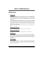
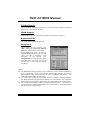
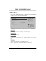
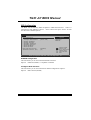
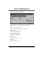
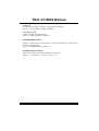
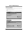
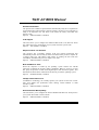
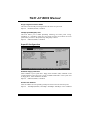
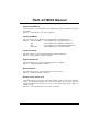
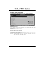
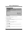
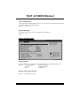
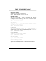
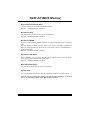
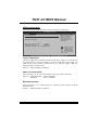
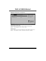
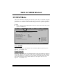
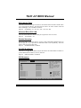
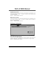
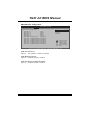
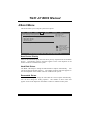
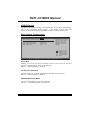
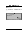
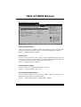
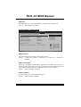
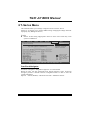
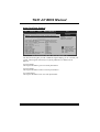
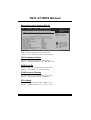
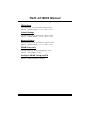
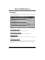
TG31-A7 BIOS Manual
BIOS Setup .................................................................................................1
1 Main Menu...............................................................................................3
2 Advanced Menu.......................................................................................7
3 PCIPnP Menu........................................................................................18
4 Boot Menu..............................................................................................22
5 Chipset Menu.........................................................................................25
6 T-S eries Menu........................................................................................29
7 Exit Menu...............................................................................................34
i
TG31-A7 BIOS Manual
BIOS Setup
Introduction
T he purpose of this manual is to describe the settings in the AMI BIOS Setup
program on this motherboard. The Setup program allows users to modify the basic
system configuration and save these settings to CMOS RAM. T he power of CMOS
RAM is supplied by a battery so that it retains the Setup information when the power
is turned off.
Basic Input-Output System (BIOS) determines what a computer can do without
accessing programs from a disk. T his system controls most of the input and output
devices such as keyboard, mouse, serial ports and disk drives. BIOS activates at the
first stag e o f the booting process, loading and executing the operating system. Some
additional features, such as virus and password prot ection or chipset fine-tuning
options are also included in BIOS.
T he rest of this manual will to guide you through the options and settings in BIOS
Setup.
Plug and Pla y Support
T his AMI BIOS supports the Plug and Play Version 1.0A specification.
EPA Green PC Support
T his AMI BIOS supports Version 1.03 of the EPA Green PC specification.
APM Support
T his AMI BIOS supports Version 1.1&1.2 of the Advanced Power Management
(APM) speci fication. Power management features are implemented via the System
Management Int errupt (SMI). Sleep and Suspend power man agement modes are
supported. Power to the hard disk drives and video monitors can also be managed by
this AMI BIOS.
ACPI Support
AMI ACPI BIOS support Version 1.0/2.0 of Advanced Configuration and Power
interface specifi cation (ACPI). It provides ASL code for pow er manag ement and
device con figuration capabilities as defined in the ACPI specification, developed by
Microso ft, Intel and T oshiba.
1
TG31-A7 BIOS Manual
PCI Bus Support
T his AMI BIOS also supports Version 2.3 of the Intel PCI (Peripheral Component
Interconn ect) local bus speci fication.
DRAM S upport
DDR2 SDRAM (Double Data Rate II Synchronous DRAM) is supported.
Supported CP Us
T his AMI BIOS supports the Intel CPU.
Using Setup
When starting up the computer, press
<Del> during the Power-On Self-Test
(POST) to enter the BIOS setup utility.
In the BIOS setup utility, you will see
General Help description at the top right
corner, and this is providing a brief
description of the selected item.
Navigation Keys for that particular menu
are at the bottom right corner, and you can
use these keys to select item and ch ange
the settings.
General Help
Navigation Keys
Notice
z
z
z
T he default BIOS settings apply for most conditions to ensure optimum performan ce
of the motherboard. If the system becomes unstable after changing any settings,
please load the default settings to ensure system’s compatibility and stability. Use
Load Setup Default under the Exit Menu.
For better system perform ance, the BIOS firmware is being continuously updated.
T he BIOS information described in this manual is for your reference only. The actual
BIOS information and settings on board may be slightly different from this manual.
T he content of this manual is subject to be chang ed without notice. We will not be
responsible for any mistakes found in this user’s manual and any system damage that
may be caused by wrong-settings.
2
TG31-A7 BIOS Manual
1 Main Menu
Once you enter AMI BIOS Setup Utility, the Main Menu will appear on the screen
providing an overview of the basic system inform ation.
Main
Advan ced
PCIPnP
BIOS SETU P U TILITY
Boot
Chipset
System Overvie w
Exit
Use [ENTER], [TAB]
or [SHIFT-TAB] to
select a field.
AMI BIOS
Version
:01. 01.01
Build Date:01/ 01/08
System Time
System Date
T-Series
Use [+] or [-] to
configure system Time.
[00: 00:00]
[Tue 01/01/2008]
Floppy A
> IDE Configur ation
+Tab
F1
F10
ESC
S elect Screen
S elect Item
C hange Field
S elect Field
G eneral Help
S ave and Exit
E xit
vxx .xx (C)Copyright 1985-200x, American Me gatrends, Inc.
AMI BIOS
Shows system information including BIOS version, built date, etc.
System Time
Set the system internal clock.
System Date
Set the system date. Note that the ‘Day’ automatically changes when you set the
date.
Floppy A
Select the type of floppy disk drive installed in your system.
Options: 360K, 5.25 in / 1.2M, 5.25 in / 720K, 3.5 in / 1.44M, 3.5 in /
2.88M, 3.5 in / None
3
TG31-A7 BIOS Manual
IDE Configuration
T he BIOS will automatically detect the presence of ID E/SAT A devices. There is a
sub-menu fo r each IDE/SAT A device. Select a device and press <Enter> to enter
the sub-menu of detailed options.
BIOS SETU P U TILITY
Main
IDE Confugurat ion
ATA/IDE Config uration
Configure SA TA Channels
>
>
>
>
>
>
Options
[Enh anced]
[Bef ore PATA]
Disabled
Compatible
Enhanced
Primary IDE Master
Primary IDE Slave
Secondary ID E Master
Secondary ID E Slave
Third IDE Ma ster
Third IDE Sl ave
Hard Disk Writ e Protect
IDE Detect Tim e Out (Sec)
[Dis abled]
[35]
S elect Screen
S elect Item
EnterG o to Sub Screen
F1
G eneral Help
F10 S ave and Exit
ESC E xit
vxx .xx (C)Copyright 1985-200x, American Me gatrends, Inc.
ATA/IDE Configuration
T his item allows you to control the onboard IDE controller.
Options: Enhanced (Default) / Compatible / Disabled
Configure SATA Channels
T his item allows you to control the SAT A channel configuration sequence..
Options: Befo re PATA (Default)
4
TG31-A7 BIOS Manual
Primary/Secondary/Third IDE Master/Slave
BIOS SETUP UTILITY
Main
Select the type
of device connected
to the system.
Primary IDE Master
Device
:
Type
[Auto]
LBA/Large Mode
[Auto]
Block (Multi-Sector Transfer)[Auto]
PIO Mode
[Auto]
DMA Mode
[Auto]
S.M.A.R.T
[Auto]
32Bit Data Transfer
[Enabled]
+F1
F10
ESC
Select Screen
Select Item
Change Option
General Help
Save and Exit
Exit
vxx.xx (C)Copyright 1985-200x, American Megatrends, Inc.
T he BIOS detects the information and values of resp ective devices, and these
information and values are shown below to the name of the sub-menu.
Type
Select the type of the IDE/SAT A drive.
Options: Auto (Default) / CDROM / ARMD / Not Installed
LBA/Large Mode
Enable or disable the LBA mode.
Options: Auto (Default) / Disabled
Block (Multi-Sector Transfer)
Enable or disable multi-sector trans fer.
Options: Auto (Default) / Disabled
PIO Mode
Select the PIO mode.
Options: Auto (Default) / 0 / 1 / 2 / 3 / 4
DMA Mode
Select the DMA mode.
Options: Auto (Default) / Disabled
5
TG31-A7 BIOS Manual
S.M.A.R.T
Set the Smart Monitoring, Analysis, and Reporting T echnology.
Options: Auto (Default) / Disabled / Enabled
32Bit Data Transfer
Enable or disable 32-bit data transfer.
Options: Enabled (Default) / Disabled
Hard Disk Write Protect
Disable or enable device write protection. T his will be effective only if the device
is accessed through BIOS.
Options: Disabled (Default) / Enabled
IDE Detect Time Out (Sec)
Select the time out value for detecting IDE/SAT A devices.
Options: 35 (Default) / 30 / 25 / 20 / 15 / 10 / 5 / 0
6
TG31-A7 BIOS Manual
2 Advanced Menu
T he Advanced Menu allows you to configu re the settings of CPU, Super I/O, Power
Management, and other system devices.
Notice
z
Beware of that setting inappropriate values in items of this menu may cause
system to malfunction.
Main
Advan ced
PCIPnP
BIOS SETU P U TILITY
Boot
Chipset
Advanced Setti ngs
T-Series
Exit
Configure CPU.
WARNING: Setti ng wrong values in below sections
may c ause system to malf unction.
>
>
>
>
>
>
CPU Configur ation
SuperIO Conf iguration
Hardware Hea lth Configuration
Smart Fan Co nfiguration
Power Config uration
USB Configur ation
S elect Screen
S elect Item
EnterG o to Sub Screen
F1
G eneral Help
F10 S ave and Exit
ESC E xit
vxx .xx (C)Copyright 1985-200x, American Me gatrends, Inc.
CPU Configuration
T his item shows the CPU information that the BIOS automatically detects.
BIOS SETU P U TILITY
Advan ced
Configure adva nced CPU settings
Module Version :xx.xx
This should be enabled
in order to enable or
disable the Hardware
Prefetcher Disable
Feature.
Manufacturer:I ntel
Frequency
:
FSB Speed
:
Cache L1
:
Cache L2
:
Ratio Actual V alue:
Hardware Prefe tcher
[En abled]
C1E Support
[Au to]
Adjacent Cache Line Prefetch [En abled]
Max CPUID Valu e Limit
[Di sabled]
Intel(R) Virtu alization Tech [En abled]
Execute-Disabl e Bit Capability[En abled]
Single Logical Processor Mode [Di sabled]
Intel(R) Speed Step(tm) tech
[En abled]
+F1
F10
ESC
S elect Screen
S elect Item
C hange Option
G eneral Help
S ave and Exit
E xit
vxx .xx (C)Copyright 1985-200x, American Me gatrends, Inc.
7
TG31-A7 BIOS Manual
Hardware Prefetcher
T he processor has a hardw are prefetch er that automatically analy zes its requirements
and prefetches dat a and instructions from the memory into the Level 2 cache that are
likely to be required in the near future. T his reduces the latency associated with
memory reads.
Options: Enabled (Default) / Disabled
C1E Support
T his item allows you to configure the Enhan ced H alt State (C1E) fun ction, which
may reduce the power consumption of your system when the system is idle.
Options: Auto (Default) / Disabled
Adj acent Cache Line Prefetch
T he processor has a h ardw are adjacent cache line prefet ch mech anism that
automatically fetches an extra 64-byte cache line whenev er the processo r requests for
a 64-byte cach e line. T his reduces cach e latency by making the next cache line
immediately available if the processor requires it as well.
Options: Enabled (Default) / Disabled
Max CPUID Value Limit
When the computer is booted up, the operating system executes the CPUID
instruction to identify the processor and its capabilities. Befo re it can do so, it must
first query the processor to find out the highest input value CPUID recognizes. T his
determines the kind of basic information CPUID can provide the operating system.
Options: Disabled (Default) / Enabled
Intel(R) Virtualization Tech
Virtualization T echnology can virtually separate your system resou rce into several
parts, thus enhance the performance when running virtual machines or multi
interface systems.
Options: Enabled (Default) / Disabled
Execute-Disable Bit Capability
T his item allows you to configure th e Execut e Disabled Bit function, which protects
your system from buffer overflow attacks.
Options: Enabled (Default) / Disabled
8
TG31-A7 BIOS Manual
Single Logical Processor Mode
T his item controls multi-processing fun ction for multi-core processors.
Options: Disabled (Default) / Enabled
Intel(R) SpeedStep(tm) Tech
T his item allows you to enable SpeedStep technology for better power saving.
SpeedStep is a technology built into some Intel processors that allows the clock
speed o f the processor to be dynamically changed by software.
Options: Enabled (Default) / Disabled
SuperIO Configuration
BIOS SETU P U TILITY
Advan ced
Configure ITE8 718 Super IO Chipse t
Onboard Floppy Controller
Serial Port1 A ddress
Parallel Port Address
Parallel Por t Mode
Parallel Por t IRQ
Keyboard Power On
Mouse PowerOn
Restore on AC Power Loss
[Ena bled]
[3F8 /IRQ4]
[378 ]
[Nor mal]
[IRQ 7]
[Dis abled]
[Dis abled]
[Pow er Off]
Allows BIOS to Enable
or Disable Floppy
Controller
+F1
F10
ESC
S elect Screen
S elect Item
C hange Option
G eneral Help
S ave and Exit
E xit
vxx .xx (C)Copyright 1985-200x, American Me gatrends, Inc.
Onboard Floppy Controller
Select enabled if your system has a floppy disk controller (FDC) installed on the
system board and you wish to use it. If you installed another FDC or the system uses
no floppy drive, select disabled in this field.
Options: Enabled (Default) / Disabled
Serial Port1 Address
Select an address and corresponding interrupt fo r the first and second seri al ports.
Options: 3F8/IRQ4 (Default) / 2F8/IRQ3 / 3E8/IRQ4 / 2E8/IRQ3 / Auto / Disabled
9
TG31-A7 BIOS Manual
Parallel Port Address
T his item allows you to determine access onboard p arallel port controller with which
I/O Address.
Options: 378 (Default) / 278 / 3BC / Disabled
Parallel Port Mode
T his item allows you to determine how the parallel port should function.
Options: Normal (Default) Using Parallel port as Standard Printer Port.
EPP
Using Parallel Port as Enhanced Parallel Port.
ECP
Using Parallel port as Extended Capabilities Port.
ECP+EPP
Using Parallel port as ECP & EPP mode.
Parallel Port IRQ
T his item allows you to select the IRQ for the onboard parallel port.
Options: IRQ7 (Default) / IRQ5 / Disabled
Keyboard Pow erOn
T his item allows you to control the keyboard power on function.
Options: Disabled (Default) / Enabled
Mouse PowerOn
T his item allows you to control the mouse power on function.
Options: Disabled (Default) / Enabled
Restore on AC Power Loss
T his setting specifies how your system should behave after a power fail or interrupts
occurs. By choosing Disabled will leave the computer in the power off state.
Choosing Enabled will restore the system to the status before power failure or
interrupt occurs.
Options: Power O ff (Default) / Power ON / Last State
10
TG31-A7 BIOS Manual
Hardware Health Configuration
T his item shows the system temperature, fan speed, and voltage information.
BIOS SETU P U TILITY
Advan ced
Hardware Healt h Configuration
H/W Health Fun ction
[Ena bled]
Shutdown Tempe rature Function[Dis abled]
Enables Hardware
Health Monitoring
Device.
CPU Temperatur e
CPU FAN Speed
SYS FAN Speed
NB FAN Speed
CPU Vcore
Chipset Voltag e
+3.30V
+5.00V
+12.0V
FSB Voltage
Memory Voltage
5V(SB)
Voltage Batter y
+F1
F10
ESC
S elect Screen
S elect Item
C hange Option
G eneral Help
S ave and Exit
E xit
vxx .xx (C)Copyright 1985-200x, American Me gatrends, Inc.
H/W Health Function
If you computer contains a monitoring system, it will show PC health status during
POST stage.
Options: Enabled (Default) / Disabled
Shutdow n Temperature Function
T his item allows you to set up the CPU shutdown T emperature. This item is only
effective under Windows 98 ACPI mode.
Options: Disabled (Default) / 60℃/140℉ / 65℃/149℉ / 70℃/158℉ / 75℃/167℉
/ 80℃/176℉ / 85℃/185℉ / 90℃/194℉
11
TG31-A7 BIOS Manual
Smart Fan Configuration
BIOS SETU P U TILITY
Advan ced
Smart Fan Conf iguration
CPU Smart Fan
Smart Fan Cali bration
Control Mode
Fan Ctrl OFF(o C)
Fan Ctrl On(oC )
Fan Ctrl Start value
Fan Ctrl Sensi tive
[Dis abled]
When you choice [Auto]
, please run the
calibration to define
the Fan parameters for
Smart Fan control
+F1
F10
ESC
S elect Screen
S elect Item
C hange Option
G eneral Help
S ave and Exit
E xit
vxx .xx (C)Copyright 1985-200x, American Me gatrends, Inc.
CPU Smart Fan
T his item allows you to control the CPU Smart Fan function.
Options: Disabled (default) / Auto
Smart Fan Calibration
Choose this item and then the BIOS will auto test and detect the CPU/System fan
fun ctions and show CPU/System fan speed.
Control Mode
T his item provides several operation modes of the fan.
Options: Quiet / Performan ce / Manual
Fan Ctrl OFF(℃ )
If the CPU/System T emperature is lower than the set value, FAN will turn off.
Options: 0~127 (℃)
Fan Ctrl On(℃ )
CPU/System fan starts to work under smart fan function when arrive this set value.
Options: 0~127 (℃)
12
TG31-A7 BIOS Manual
Fan Ctrl Start Value
When CPU/System temperature arriv es to the set value, the CPU/System fan will
work under Smart Fan Function mode.
Options: 0~127 (℃)
Fan Ctrl Sensitive
Increasing the value will raise the speed of CPU/System fan.
Options: 1~127
Power Configuration
BIOS SETU P U TILITY
Advan ced
ACPI Settings
Suspend mode
Repost Video o n S3 Resume
ACPI Version F eatures
ACPI APIC supp ort
AMI OEMB table
Headless mode
Energy Lake Fe ature
APIC ACPI SCI IRQ
USB Device Wak eup From S3/S4
High Performan ce Event Timer
[S1( POS)]
[NO]
[ACP I v1.0]
[Ena bled]
[Ena bled]
[Dis abled]
[Dis abled]
[Dis abled]
[Dis abled]
[Dis abled]
Advanced Resum e Event Controls
Resume On Ri ng
[D isabled]
Resume On PM E#
[D isabled]
Resume On RT C Alarm
[D isabled]
RTC Alarm Da te(Days)
System Time
Select the ACPI
state used for
System Suspend.
+F1
F10
ESC
S elect Screen
S elect Item
C hange Option
G eneral Help
S ave and Exit
E xit
vxx .xx (C)Copyright 1985-200x, American Me gatrends, Inc.
Suspend mode
T he item allows you to select the suspend type under the ACPI operating system.
Options: S1 (POS) (Default)
Power on Suspend
S3 (ST R)
Suspend to RAM
Auto
POS+STR
Repost Video on S3 Resume
Options:
NO (Default) / YES
13
TG31-A7 BIOS Manual
ACPI Version Features
T he item allows you to select the version of ACPI.
Options: ACPI v1.0 (Default) / ACPI v2.0 / ACPI v3.0
ACPI APIC support
T his item is used to enable or disable the motherboard's APIC (Advan ced
Programmable Interrupt Controller). The APIC provides multiprocessor support,
more IRQs and faster interrupt handling.
Options: Enabled (Default) / Disabled
AMI OEMB table
Set this value to allow the ACPI BIOS to add a pointer to an OEMB table in the Root
System Description T able (RSDT ) table.
Options: Enabled (Default) / Disabled
Headless mode
T his is a server-speci fic feature. A headless server is one that operates without a
keyboard, monitor or mouse. To run in headless mode, both BIOS and operating
system (e.g. Windows Server 2003) must support headless operation.
Options: Disabled (Default) / Enabled
Energy Lake Feature
T his item allows you control the energy lake feature.
Options: Disabled (Default) / Enabled
APIC ACPI SCI IRQ
Options:
Disabled (Default) / Enabled
USB Dev ice Wakeup from S3/S4
T his item allows you to enable or disabled the USB resume from S3/S4 function.
Options: Disabled (Default) / Enabled
14
TG31-A7 BIOS Manual
High Performance Event Timer
T his item allows you to enable or disabled the HPET.
Options: Disabled (Default) / Enabled
Resume On Ring
T his item allows you control the wake on ring function.
Options: Disabled (Default) / Enabled
Resume On PME#
When you select Enabled, a PME signal from PCI card returns the system to Full ON
state.
For this function to work, you may need a LAN add-on card which supports the
Wake on LAN function. Set the Wake on LAN (WOL) jumper on motherboard to
enable i f applicable.
Options: Disabled (Default) / Enabled
Resume On RTC Alarm
When “ Enabled”, you can set the date and time at which the RT C (real-time clock)
alarm awak ens the system from Suspend mode.
Options: Disabled (Default) / Enabled
RTC Alarm Date (Days)
You can choose which date the system will boot up.
System Time
You can choose the system boot up time, input hour, minute and second to specify.
Note: If you have change the setting, you must let the system boot up until it
goes to the operating system, before this function will work.
15
TG31-A7 BIOS Manual
USB Configuration
T his item shows the USB controller and using USB device information.
BIOS SETU P U TILITY
Advan ced
USB Configurat ion
Enables support for
legacy USB. AUTO
option disables
legacy support if
no USB devices are
connected.
Module Version - 2.24.2-13.4
USB Devices En abled:
Legacy USB Sup port
USB 2.0 Contro ller Mode
BIOS EHCI Hand -Off
[Ena bled]
[HiS peed]
[Ena bled]
> USB Mass Sto rage Device Configu ration
+F1
F10
ESC
S elect Screen
S elect Item
C hange Option
G eneral Help
S ave and Exit
E xit
vxx .xx (C)Copyright 1985-200x, American Me gatrends, Inc.
Legacy USB Support
T his item determines if the BIOS should provide legacy support fo r USB devices
like the keyboard, mouse, and USB drive. T his is a useful feature when using such
USB devices with operating systems that do not natively support USB (e.g.
Microso ft DOS or Windows NT).
Options: Enabled (Default) / Disabled
USB 2.0 Controller Mode
T his item allows you to select the operation mode of the USB 2.0 controller.
Options: HiSpeed (Default) USB 2.0-480Mbps
FullSpeed
USB 1.1-12Mbps
BIOS EHCI Hand-Off
T his item allows you to enable support for op erating systems without an EHCI
hand-o ff feature.
Options: Enabled (Default) / Disabled
16
TG31-A7 BIOS Manual
USB Mass Storage Dev ice Configuration
BIOS SETUP UTILITY
Advanced
USB Mass Storage Device Configuration
USB Mass Storage Reset Delay [20 Sec]
Device #
Emulation Type
Number of seconds
POST waits for the
USB mass storage
device after start
unit command.
[Auto]
+F1
F10
ESC
Select Screen
Select Item
Change Option
General Help
Save and Exit
Exit
vxx.xx (C)Copyright 1985-200x, American Megatrends, Inc.
USB Mass Storage Reset Delay
T his item allows you to set the reset delay for USB mass storage device.
Options: 20 Sec (Default) / 10 Sec / 30 Sec / 40 Sec
Emulation Type
T his item allows you to select the emulation type of the USB mass storage device.
Options: Auto (Default) / Floppy / Forced FDD / Hard Disk / CDROM
17
TG31-A7 BIOS Manual
3 PCIPnP Menu
T his section describes con figuring the PCI bus system. PCI, or Personal Computer
Interconn ect, is a system which allows I/O devices to operate at speeds nearing the
speed o f the CPU itself uses when communicating with its own special components.
Notice
z
Beware of that setting inappropriate values in items of this menu may cause
system to malfunction.
Main
Advan ced
PCIPnP
BIOS SETU P U TILITY
Boot
Chipset
Advanced PCI/P nP Settings
T-Series
Exit
Clear NVRAM during
System Boot.
WARNING: Setti ng wrong values in below sections
may c ause system to malf unction.
Clear NVRAM
Plug & Play O/ S
PCI Latency Ti mer
Allocate IRQ t o PCI VGA
Palette Snoopi ng
PCI IDE BusMas ter
[No]
[No]
[64]
[Yes ]
[Dis abled]
[Ena bled]
> PCI Resource
> PCI Express Configuration
+F1
F10
ESC
S elect Screen
S elect Item
C hange Option
G eneral Help
S ave and Exit
E xit
vxx .xx (C)Copyright 1985-200x, American Me gatrends, Inc.
Clear NV RAM
T his item allows you to clear the data in the NVRAM (CMOS) by selecting “Yes”.
Options: No (Default) / Yes
Plug & P lay OS
When set to YES, BIOS will only initialize the PnP cards used for the boot sequen ce
(VGA, IDE, SCSI). The rest of the cards will be initialized by the PnP operating
system like Window™ 95. When set to NO, BIOS will initialize all the PnP cards.
For non-PnP operating systems (DOS, Netware™), this option must set to NO.
Options: No (Default) / Yes
18
TG31-A7 BIOS Manual
PCI Latency Timer
T his item controls how long a PCI device can hold the PCI bus before another takes
over. T he longer the latency, the longer the PCI device can retain control of the bus
before handing it over to another PCI device.
Options: 64 (Default) / 32 / 96 / 128 / 160 / 192 / 224 / 248
Allocate IRQ to PCI V GA
T his item allows BIOS to choose a IRQ to assign for the PCI VGA card.
Options: Yes (Default) / No
Palette Snooping
Some old graphic controllers need to “ snoop” on the VGA palette and then map it to
their display as a way to provide boot information and VGA compatibility. This item
allows such snooping to take place.
Options: Disabled (Default) / Enabled
PCI IDE BusMaster
T his item is a toggle for the built-in driver that allows the onbo ard ID E controller to
perform DMA (Direct Memory Access) trans fers.
Options: Enabled (Default) / Disabled
PCI Resource
BIOS SETU P U TILITY
PCIPnP
PCI Resource
IRQ3
IRQ4
IRQ5
IRQ7
IRQ9
IRQ10
IRQ11
IRQ14
IRQ15
DMA
DMA
DMA
DMA
DMA
DMA
[Ava ilable]
[Ava ilable]
[Ava ilable]
[Ava ilable]
[Ava ilable]
[Ava ilable]
[Ava ilable]
[Ava ilable]
[Ava ilable]
Channel
Channel
Channel
Channel
Channel
Channel
0
1
3
5
6
7
[Ava ilable]
[Ava ilable]
[Ava ilable]
[Ava ilable]
[Available]
[Ava ilable]
Available: Specified
IRQ is available to be
used by PCI/PnP
devices.
Reserved: Specified
IRQ is reserved for
use by Legacy ISA
devices.
+F1
F10
ESC
S elect Screen
S elect Item
C hange Option
G eneral Help
S ave and Exit
E xit
vxx .xx (C)Copyright 1985-200x, American Me gatrends, Inc.
19
TG31-A7 BIOS Manual
IRQ3/4/5/7/9/10/11/14/15
T hese items will allow you to assign each system interrupt a type, depending on the
type of device using the interrupt. T he option “Available” means the IRQ is going
to assign automatically.
Options: Available (Default) / Reserved
DMA Channel 0/1/3/5/6/7
T hese items will allow you to assign each DMA channel a type, depending on the
type of device using the channel. T he option “ Available” means the channel is
going to assign automatically.
Options: Available (Default) / Reserved
PCI Express Configuration
BIOS SETU P U TILITY
PCIPnP
PCI Express Co nfiguration
Active State P ower-Management[Dis abled]
> SB PCIE Port s Configuration
Enable/Disable
PCI Express L0s and
L1 link power
states.
+F1
F10
ESC
S elect Screen
S elect Item
C hange Option
G eneral Help
S ave and Exit
E xit
vxx .xx (C)Copyright 1985-200x, American Me gatrends, Inc.
Active State Power-Management
T his item sets the ASPM configuration for the PCI Express devices b efore the
operating system boots. T his function is for OS which does not support ASPM.
Options: Disabled (Default) / Enabled
20
TG31-A7 BIOS Manual
SB PCIE Ports Configuration
BIOS SETU P U TILITY
PCIPnP
PCIE Ports Con figuration
PCIE Port 0
PCIE Port 1
PCIE Port 2
PCIE Port 3
PCIE Port 4
PCIE Port 5
PCIE High Pr iority Port
PCIE
PCIE
PCIE
PCIE
PCIE
PCIE
Port
Port
Port
Port
Port
Port
0
1
2
3
4
5
IOxAPIC
IOxAPIC
IOxAPIC
IOxAPIC
IOxAPIC
IOxAPIC
Enable
Enable
Enable
Enable
Enable
Enable
Options
[Aut o]
[Aut o]
[Aut o]
[Aut o]
[Aut o]
[Aut o]
[Dis abled]
[Dis abled]
[Dis abled]
[Dis abled]
[Dis abled]
[Dis abled]
[Dis abled]
Auto
Enabled
Disabled
+F1
F10
ESC
S elect Screen
S elect Item
C hange Option
G eneral Help
S ave and Exit
E xit
vxx .xx (C)Copyright 1985-200x, American Me gatrends, Inc.
PCIE Port 0/1/2/3/4/5
Options: Auto (Default) / Enabled / Disabled
PCIE High Priority Port
Options: Disabled (Default) / Enabled
PCIE Port 0/1/2/3/4/5 IOxAPIC Enable
Options: Disabled (Default) / Enabled
21
TG31-A7 BIOS Manual
4 Boot Menu
T his menu allows you to setup the system boot options.
Main
Advan ced
PCIPnP
BIOS SETU P U TILITY
Boot
Chipset
Boot Settings Configuration
>
>
>
>
T-Series
Exit
Specifies the
Boot Device
Priority sequence.
Boot Device Priority
Hard Disk Dr ives
Removable Dr ives
CD/DVD Drive s
> Boot Setting s Configuration
S elect Screen
S elect Item
EnterG o to Sub Screen
G eneral Help
F1
F10 S ave and Exit
ESC E xit
vxx .xx (C)Copyright 1985-200x, American Me gatrends, Inc.
Boot De vice Priority
Items in this sub-menu specify the boot device priority sequence from the available
devices. T he number of device items that appears on the screen depends on the
number of devi ces installed in the system.
Hard Disk Drives
T he BIOS will attempt to arrange the hard disk boot sequence automatically. You
can also ch ange the booting sequence. T he number of device items that appears on
the screen depends on the number of devices installed in the system.
Removable Drives
T he BIOS will attempt to arrange the removable drive boot sequence automatically.
You can also change the booting sequence. The number of device items that
appears on the screen depends on the number of devices installed in the system.
22
TG31-A7 BIOS Manual
CD/DV D Drives
T he BIOS will attempt to arrange the CD/DVD drive boot sequence automatically.
You can also change the booting sequence. The number of device items that
appears on the screen depends on the number of devices installed in the system.
Boot Settings Configuration
BIOS SETU P U TILITY
Boot
Boot Settings Configuration
Quick Boot
Full Screen LO GO Show
AddOn ROM Disp lay Mode
Bootup Num-Loc k
[Ena bled]
[Ena bled]
[For ce BIOS]
[ON]
Allows BIOS to skip
certain tests while
booting. This will
decrease the time
needed to boot the
system.
+F1
F10
ESC
S elect Screen
S elect Item
C hange Option
G eneral Help
S ave and Exit
E xit
vxx .xx (C)Copyright 1985-200x, American Me gatrends, Inc.
Quick Boot
Enabling this option will cause an ab ridged version o f the Power On Sel f-T est
(POST ) to execute after you power up the computer.
Options: Enabled (Default) / Disabled
Full Screen LOGO Show
T his item allows you to enable/disable Full Screen LOGO Show function.
Options: Enabled (Default) / Disabled
AddOn ROM Display Mode
T his item sets the display mode for option ROM.
Options: Force BIOS (Default) / Keep Current
23
TG31-A7 BIOS Manual
Bootup Num-L ock
Selects the NumLock State after the system switched on.
Options: ON (Default) / OFF
24
TG31-A7 BIOS Manual
5 Chipset Menu
T his submenu allows you to configure the speci fic features of the chipset installed on
your system. T his chipset manage bus speeds and access to system memory
resources, such as DRAM. It also coordinates communications with the PCI bus.
Notice
z
Beware of that setting inappropriate values in items of this menu may cause
system to malfunction.
Main
Advan ced
PCIPnP
BIOS SETU P U TILITY
Boot
Chipset
Advanced Chips et Settings
T-Series
Exit
Configure North Bridge
features
WARNING: Setti ng wrong values in below sections
may c ause system to malf unction.
> North Bridge Configuration
> South Bridge Configuration
S elect Screen
S elect Item
EnterG o to Sub Screen
G eneral Help
F1
F10 S ave and Exit
ESC E xit
vxx .xx (C)Copyright 1985-200x, American Me gatrends, Inc.
25
TG31-A7 BIOS Manual
North Bridge Configuration
BIOS SETU P U TILITY
Chipset
North Bridge C hipset Configuratio n
Memory Remap F eature
PCI MMIO All ocation:
Memory Hole
[E nabled]
[D isabled]
ENABLE: Allow
remapping of
overlapped PCI memory
above the total
physical memory.
Initiate Graph ic Adapter
Internal Graph ics Mode Select
[P EG/PCI]
[E nabled,8MB]
DISABLE: Do not allow
remapping of memory.
PEG Port Confi guration
PEG Port
[A uto]
+F1
F10
ESC
S elect Screen
S elect Item
C hange Option
G eneral Help
S ave and Exit
E xit
vxx .xx (C)Copyright 1985-200x, American Me gatrends, Inc.
Memory Remap Feature
T his item allows you to enable or disable the remapping of the overlapped PCI
memory above the total physical memory. Only 64-bit OS supports this function.
Options: Enabled (Default) / Disabled
Memory Hole
You can reserve this area of system memory for ISA adapter ROM. When this area
is reserved it cannot be cached. Check the user information of peripherals that need
to use this area o f system memory for the memory requirements.
Options: Disabled (Default) / Enabled
Initiate Graphic Adapter
T his item allows you to enable or disable VGA controller.
Options: PEG/PCI (Default) / PEG / PCI
Internal Graphics Mode Select
T his item will be different as your memory modules. When the memory size is
decided, this frame bu ffer size will also be fixed.
Options: Enabled,8MB (Default) / Enabled,1MB / Disabled
26
TG31-A7 BIOS Manual
PEG Port
T his BIOS feature is a toggle that enables or disables the PCI Express port.
Options: Auto (Default) / Disabled
South Bridge Configuration
BIOS SETU P U TILITY
Chipset
South Bridge C hipset Configuratio n
Options
USB Functions
USB 2.0 Contro ller
Audio Controll er
[8 USB Ports]
[E nabled]
[A zalia]
Onboard Lan Co ntrol
Onboard Lan Bo ot ROM
MAC ID Informa tion
[E nabled]
[D isabled]
SMBUS Controll er
[E nabled]
SLP_S4# Min. A ssertion Width
[1 to 2 seconds]
Disabled
2 USB Ports
4 USB Ports
6 USB Ports
8 USB Ports
+F1
F10
ESC
S elect Screen
S elect Item
C hange Option
G eneral Help
S ave and Exit
E xit
vxx .xx (C)Copyright 1985-200x, American Me gatrends, Inc.
USB Functions
T he item determines the number of functional USB port.
Options: 8 USB Ports (Default) / 6 USB Ports / 4 USB Ports / 2 USB Ports /
Disabled
USB 2.0 Controller
T his entry is to enabled/ disabled EHCI controller only. T his Bios itself may/may not
have high speed USB support. If the Bios has high speed USB support built in,the
support will be automately turn on when high speed device were attached.
Options: Enabled (Default) / Disabled
Audio Controller
T his item allows you to select the Audio support.
Options: Azalia (D efault) / Disabled
27
TG31-A7 BIOS Manual
Onboard Lan Control
T his item allows you to enable or disable the Onboard LAN.
Options: Enabled (Default) / Disabled
Onboard Lan Boot Rom
T his item allows you to select the Onboard LAN Boot ROM.
Options: Disabled (Default) / Enabled
MAC ID Information
T his item shows the LAN MAC ID.
SMBUS Controller
T his BIOS feature controls the I/O buffers fo r the SMBus.
Options: Enabled (Default) / Disabled
SLP_S4# Min. Assertion Width
Options:
1 to 2 seconds (Default)
28
TG31-A7 BIOS Manual
6 T-Series Menu
T his submenu allows you to change voltage and clock of various devices.
(Howev er, we suggest you to use the default setting. Changing the voltage and clock
improperly may damage the device.)
Notice
z
Beware of that setting inappropriate values in items of this menu may cause
system to malfunction.
Main
Advan ced
PCIPnP
BIOS SETU P U TILITY
Boot
Chipset
T-Series Setti ngs
T-Series
Exit
Options
WARNING: Setti ng wrong values in below sections
may c ause system to malf unction.
OverClock Navi gator
[N ormal]
=========== Au tomate OverClock Sy stem ===========
Auto OverClock System
[V 6-Tech Engine]
============ M anual OverClock Sys tem ============
CPU Frequency Setting
[2 00]
PCIE Clock By
[A uto]
PCIE Frequency Setting
[1 00]
CPU Voltage
[D efault]
FSB Voltage
[D efault]
Chipset Voltag e
[D efault]
Memory Voltage
[D efault]
DRAM Frequency
[A uto]
Configure DRAM Timing by SPD
[E nabled]
Integrated Mem ory Test
[D isabled]
Normal
Automate OverClock
Manual OverClock
S elect Screen
S elect Item
EnterG o to Sub Screen
F1
G eneral Help
F10 S ave and Exit
ESC E xit
vxx .xx (C)Copyright 1985-200x, American Me gatrends, Inc.
OverClock Navigator
OverClock .Navigator is designed for beginners in overclock field.
Based on many test and experiments from Biostar Engineer Team, OverClock
Navigator provid es 3 default overclo ck con figurations that are able to raise the
system perfo rmance.
Options: Normal (Default) / Automate OverClock / Manual OverClock
29
TG31-A7 BIOS Manual
Auto OverClock S ystem
Main
Advan ced
PCIPnP
BIOS SETU P U TILITY
Boot
Chipset
T-Series
T-Series Setti ngs
Exit
Options
WARNING: Setti ng wrong values in below sections
may c ause system to malf unction.
OverClock Navi gator
[A utomate OverClock]
=========== Au tomate OverClock Sy stem ===========
Auto OverClock System
[V 6-Tech Engine]
============ M anual OverClock Sys tem ============
CPU Frequency Setting
[2 00]
PCIE Clock By
[A uto]
PCIE Frequency Setting
[1 00]
CPU Voltage
[D efault]
FSB Voltage
[D efault]
Chipset Voltag e
[D efault]
Memory Voltage
[D efault]
DRAM Frequency
[A uto]
Configure DRAM Timing by SPD
[E nabled]
Integrated Mem ory Test
[D isabled]
Normal
Automate OverClock
Manual OverClock
S elect Screen
S elect Item
EnterG o to Sub Screen
G eneral Help
F1
F10 S ave and Exit
ESC E xit
vxx .xx (C)Copyright 1985-200x, American Me gatrends, Inc.
T he Overclock Navig ator provides 3 different engines helping you to overclock your
system. T hese engines will boost your system performan ce to different level.
Options:
V6 Tech Engine
T his engine will make a good over-clock perfo rmance.
V8 Tech Engine
T his engine will make a better over-clo ck perfo rmance.
V12 T ech Engine
T his engine will make a best over-clock performance.
30
TG31-A7 BIOS Manual
Manual Overclock System (M.O.S.)
Main
Advan ced
PCIPnP
BIOS SETU P U TILITY
Boot
Chipset
T-Series
T-Series Setti ngs
Exit
Options
WARNING: Setti ng wrong values in below sections
may c ause system to malf unction.
OverClock Navi gator
[M anual OverClock]
=========== Au tomate OverClock Sy stem ===========
Auto OverClock System
[V 6-Tech Engine]
============ M anual OverClock Sys tem ============
CPU Frequency Setting
[2 00]
PCIE Clock By
[A uto]
PCIE Frequency Setting
[1 00]
CPU Voltage
[D efault]
FSB Voltage
[D efault]
Chipset Voltag e
[D efault]
Memory Voltage
[D efault]
DRAM Frequency
[A uto]
Configure DRAM Timing by SPD
[E nabled]
Integrated Mem ory Test
[D isabled]
Normal
Automate OverClock
Manual OverClock
S elect Screen
S elect Item
EnterG o to Sub Screen
G eneral Help
F1
F10 S ave and Exit
ESC E xit
vxx .xx (C)Copyright 1985-200x, American Me gatrends, Inc.
MOS is designed for experienced overclock users.
It allows users to customize personal overclock setting.
CPU Frequency Setting
T his item allows you to select the CPU Frequency.
Options: 200 (MHz) (Default) / Min= 200; Max= 600
PCIE Clock By
T his item allows you to select the PCIE clock control
Options: Auto (Default) / Fixed 100 / Manual
PCIE Frequency Setting
T his item allows you to select the PCIE clock control
Options: 100 (Default) / Min=100; Max=200
CPU Voltage
T his item allows you to select CPU Voltage Control.
Options: Default (Default) / +0.1V / +0.2V / +0.3V
31
TG31-A7 BIOS Manual
FS B Voltage
T his item allows you to select FSB Voltage Control.
Options: Default (Default) / +0.1V / +0.2V / +0.3V
Chipset Voltage
T his item allows you to select chipset Voltage Control.
Options: Default (Default) / +0.1V / +0.2V / +0.3V
Memory Voltage
T his item allows you to select memory Voltage Control.
Options: Default (Default) / +0.1V / +0.2V / +0.3V
DRAM Frequency
T his item allows you to control the Memory Clock.
Options: Auto (Default) / Limit
Configure DRAM Timing by SP D
Options:
Enabled (Default) / Disabled
32
TG31-A7 BIOS Manual
Integrated Memory Test
Integrat ed Memory T est allows users to test memory module compatibilities without
additional device or softw are.
Step 1:
T his item is disabled on default; change it to “ Enable” to precede memory test.
Main
Advan ced
PCIPnP
BIOS SETU P U TILITY
Boot
Chipset
Exit
T-Series
T-Series Setti ngs
Options
WARNING: Setti ng wrong values in below sections
may c ause system to malf unction.
OverClock Navi gator
[N ormal]
=========== Au tomate OverClock Sy stem ===========
Auto OverClock System
[V 6-Tech Engine]
============ M anual OverClock Sys tem ============
CPU Frequency Setting
[2 00]
PCIE Clock By
[A uto]
PCIE Frequency Setting
[1 00]
CPU Voltage
[D efault]
FSB Voltage
[D efault]
Chipset Voltag e
[D efault]
Memory Voltage
[D efault]
DRAM Frequency
[A uto]
Configure DRAM Timing by SPD
[E nabled]
Integrated Mem ory Test
[E nabled]
Disabled
Enabled
S elect Screen
S elect Item
EnterG o to Sub Screen
G eneral Help
F1
F10 S ave and Exit
ESC E xit
vxx .xx (C)Copyright 1985-200x, American Me gatrends, Inc.
Step 2:
When the process is done, change the setting back from “Enabled” to “Disabled” to
complete the test.
Main
Advan ced
PCIPnP
BIOS SETU P U TILITY
Boot
Chipset
T-Series Setti ngs
Exit
T-Series
Options
WARNING: Setti ng wrong values in below sections
may c ause system to malf unction.
OverClock Navi gator
[N ormal]
=========== Au tomate OverClock Sy stem ===========
Auto OverClock System
[V 6-Tech Engine]
============ M anual OverClock Sys tem ============
CPU Frequency Setting
[2 00]
PCIE Clock By
[A uto]
PCIE Frequency Setting
[1 00]
CPU Voltage
[D efault]
FSB Voltage
[D efault]
Chipset Voltag e
[D efault]
Memory Voltage
[D efault]
DRAM Frequency
[A uto]
Configure DRAM Timing by SPD
[E nabled]
Integrated Mem ory Test
[D isabled]
Disabled
Enabled
S elect Screen
S elect Item
EnterG o to Sub Screen
F1
G eneral Help
F10 S ave and Exit
ESC E xit
vxx .xx (C)Copyright 1985-200x, American Me gatrends, Inc.
33
TG31-A7 BIOS Manual
7 Exit Menu
T his menu allows you to load the optimal default settings, and save or discard the
changes to the BIOS items.
Main
Advan ced
PCIPnP
BIOS SETU P U TILITY
Boot
Chipset
Exit Options
T-Series
Exit
Exit system setup
after saving the
changes.
Save Changes a nd Exit
Discard Change s and Exit
Discard Change s
F10 key can be used
for this operation.
Load Optimal D efaults
ReloadCMOS Set tings
CMOS Backup Fu nction
S elect Screen
S elect Item
EnterG o to Sub Screen
G eneral Help
F1
F10 S ave and Exit
ESC E xit
Security Setti ngs
> Security
vxx .xx (C)Copyright 1985-200x, American Me gatrends, Inc.
Save Changes and Exit
Save all configuration changes to CMOS RAM and exit setup.
Discard Changes and Exit
Abandon all changes made during the current session and exit setup.
Discard Changes
Abandon all changes made during the current session and restore the previously
saved values.
Load Optimal Defaults
T his selection allows you to reload the BIOS when problem occurs during system
booting sequence. T hese con figurations are facto ry settings optimized fo r this
system.
34
TG31-A7 BIOS Manual
CMOS Backup Function
It allows users to save different CMOS settings into BIOS-ROM and reload any
saved CMOS setting for customizing system configurations.
Moreover, users are able to save an ideal overclock setting during overclock
operation.
T here are 10 sets o f record address es in total, and users are able to nam e the CMOS
data acco rding to personal preference.
Main
Advan ced
PCIPnP
BIOS SETU P U TILITY
Boot
Chipset
T-Series
Exit
Exit Options
Save Changes a nd Exit
Discard Change s and Exit
Discard Change s
Load Optimal D efaults
ReloadCMOS Set tings
CMOS Backup Func
CMOS Data Reload
CMOS Data Save
CMOS Backup Fu nction
S elect Screen
S elect Item
EnterG o to Sub Screen
G eneral Help
F1
F10 S ave and Exit
ESC E xit
Security Setti ngs
> Security
vxx .xx (C)Copyright 1985-200x, American Me gatrends, Inc.
Security
T his sub-menu allows you to provide/revise supervisor and user password.
BIOS SETU P U TILITY
Exit
Security Setti ngs
Install or Change the
password.
Supervisor Pas sword :Not Installe d
User Password
:Not Installe d
Change Supervi sor Password
User Access Le vel
Change User Pa ssword
Clear User Pas sword
Password Check
[Ful l Access]
[Set up]
Boot Sector Vi rus Protection [Dis abled]
S elect Screen
S elect Item
EnterC hange
F1
G eneral Help
F10 S ave and Exit
ESC E xit
vxx .xx (C)Copyright 1985-200x, American Me gatrends, Inc.
35
TG31-A7 BIOS Manual
Change Supervisor Passw ord
Setting the supervisor password will prohibit everyone except the supervisor from
making changes using the CMOS Setup Utility. You will be prompted with to enter a
password.
User Acess Level
T his item allows supervisor to set the user level.
Options: Full Access (Default) / No Access / View Only / Limited
Change User Password
If the Supervisor Password is not set, then the User Password will function in the
same way as the Supervisor Password. If the Supervisor Password is set and the User
Password is set, the “User” will only be able to view configurations but will not be
able to change them.
Clear User Passw ord
T his item is for clearing user passwo rd.
Passw ord Check
T his item is for setting the timing that checking password.
Options: Setup (Default) / Always
Boot Sector Virus Protection
T his option allows you to choose the VIRUS Warning feature that is used to protect
the IDE H ard Disk boot sector. If this fun ction is enabled and an attempt is made to
write to the boot sector, BIOS will display a warning message on the screen and
sound an alarm beep.
Options: Disabled (Default) / Enabled
36