1
Congratulations!
You'vejustpurchasedanew Marey ECO240 tankless water heater and will
soon begin to enjoy the benefits of “going tankless.”
Take the time to thoroughly read and understand this safety and installation
manual in its entirety before you attempt to install your new ECO240 tankless
waterheater,asitcontainsimportantsafetytipsandinstructions.
Please carefully read all instructions and warnings. If you need assistance or
have any questions please contact us at:
1-512-332-2229
Please keep this manual for future referenceandtechnicalinformation.
WARNING
04
IMPORTANT WARNINGS
04
IMPORTANT SAFETY INFORMATIONS
04
PRODUCT FEATURES
05
PRODUCT ADVANTAGES
06
INSTALLATION DIAGRAM
07
ELECTRICAL DIAGRAM
07
TECHNICAL SPECIFICATIONS AND INSTALLATION REQUIREMENTS
08
PRODUCT INNER STRUCTURE
09
INSTALLATION GUIDELINE
10
TROUBLE-SHOOTING / DIAGNOSTIC CHART
16
CUSTOMER SERVICE
18
OTHER PRODUCTS
19
4002422
02
03
If your water heater requires a reset, be sure to TURN OFF THE BREAKER prior to
resetting the unit.
8. DO NOT switch the heater on if you suspect that it may be frozen. Wait until you are
sure that it has completely thawed out.
Resetting your unit without turning off the breaker can result in personal injury and
damage to your water heater.
9. Before taking a shower, feel the outlet hot water temperature with your hand to
make sure it is suitable for showering to avoid getting scalded.
10. Before connecting the water heater hoses to the plumbing in your home, it is
extremely important to FLUSH the lines to wash out any plumbing paste or residue in
the lines.
This is not a do-it-yourself project. If you are not familiar with basic plumbing and
electricity, we strongly recommend that this water heater be installed by a licensed
plumber or electrician.
11. The heating chamber is treated with composite nano-insulation material. It is
normal for there to be a slight odor and possibly a small amount of green/blue smoke
when the unit is used for the first time.
Installation of this product is restricted to indoor locations.
Under no circumstances should you attempt to install, repair or disassemble the
Marey Heater tankless electric water heater without first shutting off all power to the
unit directly at the circuit breaker panel.
12. If there is damage to the wiring or any internal part, you must contact a qualified
electrician to replace it, or send it to one of our service centers for repair.
Replacement parts are available from Marey.
13. The shower head should be cleaned and checked periodically for debris and
build-up.
14. This water heater must be installed vertically, per the mounting instructions.
1. The installation must be in compliance with your local electrical and plumbing
codes.
15. CAUTION: FOR HOUSEHOLD AND INDOOR USE ONLY
2. This water heater must be GROUNDED.
3. All wiring and installation must be supervised by a qualified electrician.
4. CAUTION: This product has more than one power-supply connection point.
Disconnect all power supplies before servicing.
1. Energy efficient, instantaneous heating on demand. It's tankless, so no preheating and no stand-by heat loss, which saves even more energy.
2. Micro-computer controlled, patented heating technology.
5. This water heater is not intended for use by persons (including children) with
reduced physical, sensory or mental capabilities, or lack of experience or
knowledge, unless they have been given supervision or instruction concerning the
use of the water heater by a person responsible for their safety. Children should be
supervised to ensure that they do not play with the water heater.
3. Extremely safe! Water is completely separated from electricity by multi-layers of
composite nano-insulation material, and the heater contains multiple additional
safety devices, as outlined below.
6. This water heater MUST be permanently connected to a fixed circuit breaker.
4. Low voltage/power fluctuation protection. If the unit detects an electrical
fluctuation (due to a power supply voltage drop, loose wire, etc), the electricity will be
cut-off within milliseconds by the fluctuation protector. If this occurs, the screen
displays an E2 code.
7. DO NOT install this water heater near volatile or flammable substances, near
tinder wood or near a strong magnetic field.
5. Malfunction sensor. If there is a malfunction with the temperature sensor, the
heater stops working and the screen displays an E3 code.
04
05
6. Dry-heating thermal cut-off. In case of dry heating, the electricity will be cut off and
the screen display will display an E4 code.
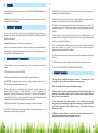
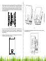
Double Pole
Circuit Breakers
7. Micro-computer features an automatic electricity and water consumption
calculating function.
ECO240
8. Reads temperature in both Fahrenheit and Celsius.
50A
50A
8/3 Wire from
Service Panel
{
Marey heating element is made from a single piece of cast aluminum, so there will
never be water leakage nor the electric leakage in the heating chamber. Marey also
have an extra stainless steel water flow channel instead of the old aluminum, so no
matter how is your water quality inside the heating element, the heat element will
service a long life.
50A
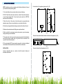
Hot
Out
Cold
In
Pressure Relief Valve
Fig. 01
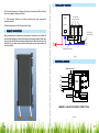
THERMAL CUT-OUT 90ºC
T1
R1
T2
R2
T3
R3
L1
L1
CONTROL
SYSTEM
L1
L2
E
DISPLAY
SCREEN
OUTLET TEMP. SENSOR
INLET TEMP. SENSOR
FLOWMETER
REMARK: J:RELAY R:HEATING SYSTEM T:TRIAC
Fig. 02
06
07
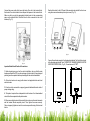
Buttom Case
Control Board
Display Screen
Up
On/Off
Down
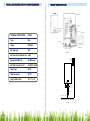
TECHNICAL SPECIFICATIONS
ECO240
Power
24Kw
Voltage
240V/60Hz
Display Screen
Temp. Sensor
Terminal Blocks
Flowmeter
Max. Amperage
100A
Fig. 03
Min. Required Circuit Breaker Size 3x40A
3x8 AWG copper
Min. Water Flow Activate Unit
0.85 GPM / 3.2 LPM
Temp. Scope
86~127º
Water Connections
3/4"NPT
Height x Width x Depth
16" x 11" x 3,5"
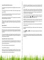
Air Switch
E
N
L
Power
Supply
2000mm
Recommended Wire Size
Sealer
Release Valve
Wash with Filer
Inlet Water
Height to the Ground
Fig. 04
08
09
NOTE: Installation must be in compliance with the National Electrical Code and
your local electrical and plumbing codes.
Front and back of the appliance (please see Fig. 05).
1. Do not install the unit in a room where there is a chance of freezing.
2. DO NOT install this water heater near tinder, volatile or flammable substances,
or near a strong magnetic field. The unit must only be mounted in a VERTICAL
position near the water fittings.
3. Mount the unit to a flat section of wall, well away from any potential water
splashes or spray. Be sure to use wall anchors, or screw directly into studs.
4. Position the unit upright with all plumbing connections at the bottom of the unit.
5. Make sure the water heater and all fittings are complete and intact.
6. Make sure that the main power supply, water pressure, ground, amperage,
voltage, and wiring meet all standards.
Fig. 05
Remove the screw which fixes the bracket on the back of the appliance (Fig. 06).
7. The water heater must be connected to a properly-grounded, dedicated branch
circuit with the proper voltage rating. The ground must be connected to the
“ground” at the circuit breaker panel.
8. This water heater MUST be permanently connected to a fixed and dedicated
circuit breaker. If the heater will be unused, switch off the circuit breaker.
Fig. 06
INSTALLATION
Remove the bracket from the appliance (Fig. 07).
Locate an appropriate place on a section of wall that meets all safety and
installation requirements.
Fig. 07
10
11
Hold the back bracket hanger in position against the wall in the desired hanging
location. Check to make sure that the bracket is level. Mark the wall where the
three mounting holes should be located. Drill holes of ¼” diameter in the marked
locations. If you are on a stud, screw the bracket directly into the wall. If you are not
on a stud, insert the plastic anchor in the hole, and secure the bracket using the
screws supplied (Fig. 08).
Fig. 08
Fig. 10
Remove (4) screws and washers (Fig 09) from the unit to free the front cover.
Carefully lift the front cover off the unit a few inches. Disengage the plug
connecting the front cover LCD panel to the body of the unit (Fig 10). Remove the
cover completely.
Fix the appliance to the hanging bracket. Make sure the unit is properly secured to
the bracket (See Fig. 11).
Please note: If LCD connection cable cannot be disengaged, simply set the front
cover aside and keep the cable connected.
Fig. 09
12
Fig. 11
13
Connect the power cable at the lower right side of the unit to the terminal block.
Each wire in the cable is labeled to correspond with spaces in the terminal block.
Make sure that you plug the appropriately labeled wire into the corresponding
space on the terminal block. Note that the unit will be connected to two circuit
breakers (Fig. 12).
Reattach the cable for the LCD panel if disconnected and reinstall the front cover
using the screws and washers previously removed. (Fig. 13).
Fig. 13
Fig. 12
Connect the cold water supply to the threaded pipe labeled “inlet” and the hot water
to the threaded pipe labeled “outlet.” IMPORTANT: RUBBER WASHER MUST BE
USED FOR PROPER SEAL. (Fig. 14) Connections are 3/4” NPT.
Important Notes About Electrical Connections:
1. Before beginning any work on the electric installation, be sure that the main
breaker panel switch is OFF to avoid any danger of electric shock. All mounting and
plumbing must be completed before proceeding with the electrical installation.
2. All electrical work must comply with national and applicable state and local
electrical codes.
3. All units must be connected to a properly grounded dedicated branch circuit of
proper voltage rating.
4. This product requires three independent circuit breakers. Use threeinsulated
wires for the three separate double-pole breakers.
5. When connecting the wires to the terminal blocks, make sure the metal wire ends
and the terminal blocks completely touch. Then, tighten the screws securely.
Failure to properly tighten can result in current escape and burning of the terminal
blocks.
14
Fig. 14
15
Important Notes About Water Connections:
1. All water pipe must comply with national and applicable state and local water
pipe codes.
2. A pressure relief valve must be installed if the cold water supply pressure
exceeds 150PSI.
3. The unit should be connected directly to the main water supply. Flush pipe with
water to remove any debris or loose particles.
4. All connections to the unit should be ¾” NPT. Larger pipe can be connected but
the appropriate adapters must be used.
5. Please remember to install rubber seal rings at the connections. When all water
connections are completed, check for leaks and take corrective action before
proceeding.
How the Unit works
1. This unit heats water instantaneously as it flows through the heating elements.
4. After the unit is supplied with power, a beep sound can be heard and an LED
lights up for 2 seconds. If no other function is turned on, the unit stands by in this
mode.
5. Press “ON/OFF” to start or stop the unit. When the unit is ON, the LED display
shows the actual water temperature of the outlet water. After 5 seconds, the screen
switches to a screen saver to conserve power. The display screen light will be off. If
you touch the screen, it will light up again.
6. The outlet water temperature can be adjusted by changing the temperature
settings on the heater. Press
and
to adjust the temperature. The range of
options for the temperature setting is 30ºC-52ºC/86ºF-127ºF.
WARNING: If the unit has been used recently, you may initially get a short burst of
very hot water from the unit. Allow a few seconds for the water to cool down to the
set point. Test the water before you take a shower.
If the unit will not be used during winter, drain out any water completely so that the
heater will not freeze.
Periodically clean the inlet filter screen and the shower head to maintain strong
water flow.
2. The electronic control monitors the flow rate and the incoming water temperature
and then switches on the required number of heating elements to reach the set
temperature.
7. Press
then press
and Celsius.
3. The outlet water temperature will be higher than the setting if the minimum flow
rate isn't met. The outlet water temperature will be lower than the setting if the
maximum flow rate is exceeded.
8. The unit features an automatic memory function to avoid repetitive operation.
When you turn on the water heater, the default set point will be the same as the last
setting used.
to convert the temperature display between Fahrenheit
Using the Water Heater - Operation Instructions
1. Turn on the water and allow it to run through the unit for a few minutes, until
water flow is continuous and all air is purged from the water pipes. Check for and
correct any leaking connections.
2. Turn on the circuit breaker to connect power to the unit.
3. Press ON/OFF to start the unit.
If there is power to the unit, but no digital display, turn off the circuit breaker. Double
check to make sure that the cable to the LCD panel on the front cover is correctly
connected inside the unit, then turn the breaker back on.
16
17
NORMAL MAINTENANCE
Problems
Possible Causes
Corrective Actions
1. Inlet and outlet
fittings leaking
A. Fittings not tight
B. Rubber washer worn-out
A. Tighten fittings.
B. Change rubber washer.
2. LED no signal
A. Power not connected.
B. LCD damaged.
C. LCD not connected to PCB.
A. Connect power to the unit.
B. Change LCD.
C. Connect LCD to the PCB Board.
3. Functional keys not
working
A. No water out from shower.
B. Water pressure too low.
C. Key or PCB damaged.
A. Open valve to get water.
B. Open valve to get pressure.
C. Change key or PCB.
4. Water too hot
A. Too high temperature set.
B. Water flow too small.
A. Set a lower temperature.
B. Open valve bigger.
5. Water too cold
A. Low temperature set.
B. Water flow too much.
A. Set a higher temperature.
B. Reduce water flow.
6. Outlet gets water
smaller and smaller.
Inlet strainer or shower clogged.
Clean strainer and shower.
7. LED displays E1
Outlet temperature is over
86ºF/127ºF.
A. Reduce the temperature.
B. Turn up the water flow.
8. LED displays E3
Temperature sensor failure.
Please contact with your local dealer.
9. LED displays E4
Dry Heating.
Shut off. Clean all outlets from any
debris, dirt, any particle or scale inside
the pipe.
10. Pressure relief
valve releases water
A. Outlet blocked.
B. Inlet pressure over 0.7Mpa.
A. Clean shower set.
B. Reduce water pressure.
11. Display overload
Inlet water flow is too big.
Reduce the inlet water flow.
Note: Do not attempt to repair this water heater yourself. Call a service person for
assistance. Always turn off the breaker before working on the unit.
To ensure consistent water flow, the following is recommended:
1. Periodically remove build-up and dirt that may accumulate at the aerator of the
faucet or in the shower head.
2. Periodically clean the built-in filter screen at the inlet connection on the water
heater. Water faucet must be turned off before cleaning the screen.
WARNING: Corrections to problems 8, 9 and 10 should only be performed by
qualified electrician. The person who initially installed the unit is the best one to
contact for help, or contact Marey for service.
18
19
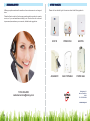
At Marey, we pride ourselves on the excellence of our customer service and support
team.
Please visit our website to get to know more about other Marey products.
Please feel free to contact us if you have any questions about our products, warranty
service, or if you need assistance installing a unit. We also strive for continuous
improvement,sowewelcome your comments, feedback and suggestions.
1-512-332-2229
[email protected]
ECO110
POWER PAK
SANTON
AQUAMATIC
GAS PORTABLE
POWER GAS
Delbrey Street, 211
San Juan, Puerto Rico
00912
Tel. 1-512-332-2229
www.marey.com
20
21