1
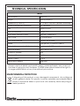
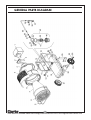
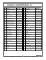
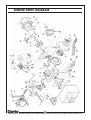
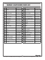
Infrared Diesel Heater
Model No: IRD40
PART NO: 6920415
OPERATING & MAINTENANCE
INSTRUCTIONS
GC0611
INTRODUCTION
Thank you for purchasing this CLARKE Diesel Infrared Heater.
Before attempting to use the heater, please read this manual throughout and
follow the instructions carefully. Thoroughly familiarise yourself with its
operation in order to ensure the safety of yourself and others around you. In
doing so you can look forward to the heater giving you long and satisfactory
service.
GUARANTEE
This product is guaranteed against faulty manufacture for a period of 12
months from the date of purchase. Please keep your receipt which will be
required as proof of purchase. This guarantee is invalid if the product is found
to have been abused or tampered with in any way, or not used for it’s
intended purpose.
Faulty goods should be returned to their place of purchase, no product can
be returned to us without prior permission. This guarantee does not effect
your statutory rights.
2
Parts & Service: 020 8988 7400/E-mail:[email protected] or [email protected]
CONTENTS
Introduction ............................................................................................ 2
Guarantee .............................................................................................. 2
General Safety Precautions .................................................................. 4
Electrical Connections .......................................................................... 6
Overview of the IRD40 Heater .............................................................. 7
Preparation ............................................................................................. 8
Operation ............................................................................................... 9
Troubleshooting .................................................................................... 11
Cleaning and Maintenance ............................................................... 13
Technical Specification ....................................................................... 14
Declaration of Conformity .................................................................. 15
Spare Parts Lists & Diagrams ............................................................... 16
3
Parts & Service: 020 8988 7400/E-mail:[email protected] or [email protected]
GENERAL SAFETY PRECAUTIONS
GENERAL
1. ALWAYS read and ensure you fully understand the following precautions
and the hazards associated with this type of heater. Do not allow anyone
who has not read these instructions to operate this heater.
2. ALWAYS check for damage before using the heater. Check for breakages
and any other condition that may affect the function of the heater. Any
damage should be properly repaired or the part replaced. If in doubt, DO
NOT use the heater and consult your local Clarke dealer.
3. NEVER carry out any modifications to this product. If experiencing difficulty
of any kind consult your local dealer.
4. Use the heater in accordance with any applicable fire regulations.
WORK AREA
1. NEVER leave a heater plugged in without adult supervision if children or
animals are likely to be present.
2. Do not expose the heater or power cable to rain or wet conditions. Any
water entering the heater will increase the risk of electric shock.
3. NEVER use the heater where petrol, paint thinners or other highly
flammable vapour or where high levels of airborne dust may be present.
5. ONLY use in well ventilated areas. NEVER use the heater in living or
sleeping areas.
6. NEVER locate the heater facing combustible materials such as screens,
workshop furniture etc.
7. DO NOT locate the heater close to an adjacent wall or ceiling. Allow a
distance of at least 3 metres from a wall or ceiling. Avoid placing the
heater directly below socket outlets.
8. ALWAYS locate the heater on a level, flat, fireproof floor. Ensure that the
heater is correctly and safely positioned as described on page 8.
9. ALWAYS ensure that ample ventilation is present if the heater is being lit
following a long period without use.
10. Disconnect the heater from the power supply when not in use.
11. NEVER leave a heater unsupervised while operating - someone should
always be made responsible for monitoring it.
12. NEVER place anything on the burner.
13. NEVER move, handle, replenish the fuel supply or adjust the heater when it
is hot, or operating. Turn it off and wait for it to cool down first.
14. NEVER attach any duct work to the front of the heater.
4
Parts & Service: 020 8988 7400/E-mail:[email protected] or [email protected]
15. ALWAYS ensure that people and animals are at least 3M away from the
front of the heater when in operation.
16. This heater will be hot when in operation and should not be touched until
it has fully cooled down after shutting off.
16. NEVER cover or impede air flow into or out of the heater.
17. Use only clean Diesel Oil. NEVER use gasoline, kerosene, paint thinners,
alcohol or other highly flammable fuels.
ELECTRICAL SAFETY
1. Electrical appliances must match the power outlet. Never modify the plug
in any way. Do not use adaptor plugs with earthed (grounded)
appliances. Correct plugs and outlets will reduce the risk of electric shock.
2. Do not abuse the electrical cable. Never use the cable for pulling or
unplugging the heater. Keep the cable away from sources of heat, oil,
sharp edges or moving parts. Damaged or tangled cables increase the
risk of electric shock.
3. Keep the mains cable well away from machines and ensure an adequate
electrical supply is close at hand so that the operation is not restricted by
the length of the cable.
4. ALWAYS disconnect from the mains supply before moving the heater or
performing any maintenance tasks.
5. Inspect the mains cable regularly for signs of damage. DO NOT use if it is
damaged and ALWAYS keep it away from the source of heat.
SERVICE & REPAIRS
1. Check the heater for damage before use. DO NOT use if the heater is
damaged. Any damage should be properly repaired or the part
replaced. If in doubt, DO NOT use the heater. Consult your local dealer.
2. When necessary, have your heater serviced or repaired by a qualified
person using identical replacement parts. This will ensure that the safety of
the heater is maintained.
Please keep these instructions in a safe place for future reference.
5
Parts & Service: 020 8988 7400/E-mail:[email protected] or [email protected]
ELECTRICAL CONNECTIONS
WARNING! Read these electrical safety instructions thoroughly
before connecting the product to the mains supply.
Before switching the machine on, make sure that the voltage of your
electricity supply is the same as that indicated on the rating plate. This
product is designed to operate using 230 VAC mains power. Connecting it to
any other power source may cause damage.
This product may be fitted with a non-rewireable plug. If it is necessary to
change the fuse in the plug, the fuse cover must be refitted. If the fuse cover
becomes lost or damaged, the plug must not be used until a suitable
replacement is obtained.
If the plug has to be changed because it is not suitable for your socket, or
due to damage, it should be cut off and a replacement fitted, following the
wiring instructions shown below. The old plug must be disposed of safely, as
insertion into a mains socket could cause an electrical hazard.
WARNING! The wires in the power cable of this product are
coloured in accordance with the following code:
Blue = Neutral
Brown = Live
Yellow and Green = Earth
If the colours of the wires in the power cable of this product do not
correspond with the terminal markings of your plug, proceed as follows.
• The wire which is coloured Blue must be connected to the terminal
which is marked N or coloured Black.
• The wire which is coloured Brown must be connected to the
terminal which is marked L or coloured Red.
• The wire which is coloured Yellow and Green must be connected to
the terminal which is marked E or
or coloured Green.
Plug must be BS1363/A approved
Earth
(Green and Yellow)
Always fit a 13 Amp fuse.
Neutral
(Blue)
Live
(Brown)
Ensure that the outer sheath of the cable is firmly held by the clamp
We strongly recommend that this machine is connected to the mains supply
via a Residual Current Device (RCD).
If in doubt, consult a qualified electrician. DO NOT attempt repairs yourself.
6
Parts & Service: 020 8988 7400/E-mail:[email protected] or [email protected]
OVERVIEW OF THE IRD40 HEATER
The IRD40 Infrared Diesel Heater is ideal for the following applications:
• Heating work areas in large, well ventilated rooms or outbuildings.
• Dust-free drying of components.
• Drying out and de-icing of construction areas, concrete, walls etc
• Defrosting large machines and buildings.
FUNCTIONAL DESCRIPTION
A pump draws fuel from the tank and drives it to the burner under pressure.
Fuel is sprayed and atomised by the nozzle and then ignited by the burner
ignition device. A built-in radial blower provides combustion airflow while air
and fuel forms a combustion mixture. The flames heat up the front plate and
guard, thus releasing heat by radiation.
The metal front guard acts as a catalyser, completing the combustion of
hydrocarbons and reducing emission pollution. The unit can be tilted at up to
20O upwards or downwards to direct heat at a particular target. The burner
pre-heater warms up the fuel before start-up and the post-ventilation
function cools down the chamber after each use. No flue or exhaust pipe is
required as all combustion gasses are catalysed during operation.
7
Parts & Service: 020 8988 7400/E-mail:[email protected] or [email protected]
PREPARATION
When unpacking, check the heater
for any damage that may have
occurred in transit and notify your
Clarke dealer immediately should
any be apparent.
Fill the tank with clean, water-free
diesel oil. When refilling, inspect the
mesh filter inside the filler neck for any
trapped contamination.
Fig 1
Note: The burner has been designed
for use with diesel fuel oil having a
maximum viscosity of 35 seconds Redwood No1 at 100OF.
Plug the heater into any suitably earthed mains power supply.
POSITIONING THE HEATER
The heater must be located on a
hard, level surface to minimise the risk
of accidental tipping or running
forward. Chock the wheels if there is
any possibility of movement.
Set the heater in position by loosening
and re-tightening the positioning
clamps on either side to achieve the
required angle of tilt.
Positioning
Clamps
Fig 2
MATERIAL CLEARANCES
It is important that the heater be positioned with at least 3 m clearance at the
front between the heater and any obstruction including walls or other
combustible surfaces. Always position the heater facing the centre of the
room. Never place any objects on, or against the heater.
Any equipment or workshop furniture should be a safe distance away as they
could be adversely affected by heat.
VENTILATION
The heater must only be installed in a room which is well ventilated. Ensure
that sufficient air is available for combustion via windows and doors,
especially if there will be people staying in the room for any length of time.
Constant occupation is not advised although the heater should be monitored
periodically.
• Ventilation is essential to reduce the dangers of oxygen depletion.
8
Parts & Service: 020 8988 7400/E-mail:[email protected] or [email protected]
HEATER OPERATION WITHOUT PEOPLE IN THE ROOM
Ensure that sufficient air is available via windows and doors for complete
combustion. The heated volume (m3)/ heat output (kW) ratio must be at least
10:1, and personnel should not stay permanently in the heated room.
HEATER OPERATION WITH PEOPLE REMAINING IN THE ROOM
If people are to remain in the room for any length of time, the heated volume
(m3) /heat output (kW) must be at least 30:1. Air circulation must be ensured
through windows and doors or permanent openings near the floor and
ceilings, whose total open area (m2) is at least 0.003 times the total heat
output (kW).
OPERATION
In normal operation, operating the ON/OFF switch will illuminate the red LED
and the green and orange warning lights. After two minutes, when the fuel
warming operation is completed, the orange warning light and the red LED
go out and the motor starts.
The following table shows the main operating phases.
Pre-heater
Green
Orange
Operation
Green
Orange
Post-ventilation
Green
Orange
Stand-by
Green
Orange
ON
OFF
Switch
I (ON)
Switch
I (ON)
Switch
O (OFF)
Switch
O (OFF)
LIGHTING THE HEATER / START-UP
To start the heater;
1. Check that there is diesel in the fuel tank.
2. Switch the ON/OFF switch to ON.
• The green and orange LEDs will light up for the duration of the pre-heating
time.
• Ignition does not take place immediately but after a pre-heating time
followed by a ‘pre-purge’ time of about 30 seconds.
9
Parts & Service: 020 8988 7400/E-mail:[email protected] or [email protected]
• If no fuel flows to the burner within
4 seconds, the heater
automatically goes into ‘lockout’
mode. In this case, check and
eliminate possible causes of ‘lockout’, referring to
TROUBLESHOOTING, then press the
RESET button to restart the heater.
If the heater does not start, check it is
not directly aimed towards a bright
light, which could interfere with the
operation of the burner control photocell.
Fig 3
Red LED/
Reset button
ON/OFF
Switch
Green/Orange LEDs
POSSIBLE FAULTS ON STARTUP
A technical fault on start-up usually makes the “Lock-out’ lamp illuminate. This
is built into the reset button on the front of the control box as shown in Fig 3.
When this happens, the controls of the burner are at ‘lock-out’. The burner
can only be lit after pushing the reset button and if, after this, the burner
operates correctly, the lock-out can be attributed to a temporary fault such
as a fluctuation in voltage.
If the lock-out continues, the cause must be determined & a solution found.
Request a qualified heater service technician to investigate the problem.
Refer to the following tables for a list of possible faults and their cause.
TURNING THE HEATER OFF
1. To stop, set the ON/OFF switch to off.
• The fan will continue running for a pre-set time while the heater cools
down.
WARNING; NEVER SWITCH OFF THE HEATER BY DISCONNECTING IT
FROM THE POWER SUPPLY.
10
Parts & Service: 020 8988 7400/E-mail:[email protected] or [email protected]
TROUBLESHOOTING
PROBLEM
CAUSE
SOLUTION
Heater fails to start when
the switch is set to ON.
No electrical supply.
Check mains, switch and fuses.
Defective on/off switch Request your service technician
to replace on/off switch.
Heater starts but
malfuctions almost
immediately.
Burner Lock-Out.
Reset burner. If lock-out repeats,
reset after 4-5 minutes.
Defective motor/
capacitor.
Request your service technician
to check motor/capacitor &
replace if necessary.
No fuel in tank.
Air in the fuel line.
Fuel filter clogged.
Burner locked out.
Refill fuel tank.
Check fuel line for leaks.
Replace fuel filter cartridge.
Request your service technician
to inspect burner.
Heater operates but the Lack of fuel in tank.
combustion is smokey.
Moisture in the fuel.
Fill the tank completely with
clean fuel.
Fuel filter is clogged.
Clean out the filter.
Airlock in fuel line.
T ighten fuel line connections.
Blocked nozzle.
Request your service technician
to clean/replace nozzle.
Contamination in main
filter.
Request your service technician
to replace oil pre-heater
Defective solenoid
valve.
Request your service technician
to replace.
Burner fan continues
running after the heater
has been switched off
and has cooled down.
Defective postventilation relay.
Request your service technician
to replace post-ventilation relay.
All LEDs are off and the
burner does not start
when the switch is set to
on.
Lack of electrical
supply.
Check mains, switch and fuses.
Request your service technician
to check the 7-pin plug and
check the thermostat is not
locked out.
Incorrect connections
in the control box.
Request your service technician
to check the connections
Burner is locked out.
Reset the burner. If lockout
repeats, reset after 4-5 minutes.
Defective
motor/capacitor.
Request your service technician
to check motor/capacitor.
Replace if necesary.
11
Parts & Service: 020 8988 7400/E-mail:[email protected] or [email protected]
TROUBLESHOOTING
PROBLEM
CAUSE
SOLUTION
Orange LED remains on
and burner will not start.
Heater and start
thermostat are faulty.
Request your service technician
to replace defective item.
Green LED is on and the
burner remains in the
pre-purge phase.
The photoelectric
sensor sees a false
light.
Eliminate the daylight.
Burner runs normally in
the pre-purge and
ignition cycle but locks
out after approx 5
seconds.
The photo-resistance
is dirty or defective.
Request your service technician
to clean or replace it.
Flame too far away
from fuel or flame
goes out.
Request your service technician
to check for delivery of fuel.
Check air output.
Change nozzle.
Check the coil of the soleniod
valve.
Burner starts but with
delayed ignition.
Ignition electrodes
wrongly positioned.
Request your service technician
to adjust them.
Air output is too high.
Request your service technician
to reset the air output.
Nozzle dirty or worn.
Request your service technician
to clean or replace it.
12
Parts & Service: 020 8988 7400/E-mail:[email protected] or [email protected]
CLEANING AND MAINTENANCE
WARNING: ALWAYS ENSURE THE HEATER HAS COOLED DOWN BEFORE
PERFORMING ANY MAINTENANCE TASKS
Before carrying out any adjustment or maintenance, ensure the heater is
switched OFF, disconnected from the mains supply, and has been given
adequate time to cool down.
CLEANING
1. Use a damp cloth wrung out in a solution of soapy water to clean the
exterior of the heater. Use household cleaners on difficult spots.
2. Never use abrasive cleaners as they may damage the paint finish.
3. The internal heating surfaces and combustion chamber of the burner
should be cleaned at least annually.
GENERAL MAINTENANCE
Correct maintenance is vital for smooth operation of the burner in order to
avoid wasting fuel and causing atmospheric pollution.
1. This heater should be inspected, cleaned and serviced annually by a
qualified service engineer. Unauthorised persons should not attempt to
carry out repairs of the burner components.
2. Replace the fuel filter cartridge if
water or dirt particles can be seen
in the glass filter bowl and at
approx 200-300 operating hours.
Fig 4
3. Empty the tank and refill with fresh
fuel if you suspect the fuel has
become contaminated with dirt
or water.
In the event of damage or broken
components, replacements are
available from Clarke Parts & Service.
STORAGE
1. For long term storage, always store the heater in a well ventilated area
away from combustible materials. Cover the heater and keep the unit dry
and dust free.
2. Store the heater in a level position when filled, or fuel leakage may occur.
13
Parts & Service: 020 8988 7400/E-mail:[email protected] or [email protected]
TECHNICAL SPECIFICATION
IRD40
Part Number
6920415
Weight
54.5 kg (empty)
Dimensions (L x W x H )
971 x 630 x 1000 mm (burner horizontal)
Burner tilt angle from horizontal
20O up/down
Fuel
Diesel Oil only
Fuel Consumption
3 kg/h + 4%
Max Rated Thermal Output
38.3 kW (130685 BTU)
Duty Cycle
S1 (continuous)
Fuel Pump Pressure
Factory set @ 9 bar
N ozzle
0.85 gph 80OH (Danfoss type H)
Air Lock (damper valve) Adjustment
Factory set @ 2.75 on scale
Electrical Supply
230 V 50 Hz 1 ph
Protection Degree
IP40
Absorbed Power
185 W
Rated Current
0.75 A
Rated Motor Speed
2850 rpm
Please note that details and specifications contained herein, are correct at
the time of going to print. However, CLARKE International reserve the right to
change specifications at any time without prior notice.
ENVIRONMENTAL PROTECTION
If disposing of this product or any damaged components, do not dispose
of with general waste. This product contain valuable raw materials Metal
products should be taken to your local civic amenity site for recycling of
metal products.
14
Parts & Service: 020 8988 7400/E-mail:[email protected] or [email protected]
DECLARATION OF CONFORMITY
15
Parts & Service: 020 8988 7400/E-mail:[email protected] or [email protected]
GENERAL PARTS DIAGRAM
16
Parts & Service: 020 8988 7400/E-mail:[email protected] or [email protected]
GENERAL COMPONENTS PARTS LIST
No Parts List
Part No
No Parts List
Part No
1
Oil Burner Assembly
AX20590036
23 Wheel Cap
AX20050015
2
Handle
AX20010006
24 Spring
AX20230227
3
Bracket
AX20630274
25 Tank Foot
AX20630020
4
Exterior Cone
AX20620947
26 Cap
AX20050010
5
Cover
AX20620942
27 Filler Filter
AX20190005
6
Cone Support Ring
AX20620937
28 Cap
AX20050000
7
Insulating Cone
AX20060023
29 Fitting
AX20120001
8
Radiation Guard
AX20240043
30 Nut
AX20100008
9
Front Guard Frame
AX20610107
31 Fitting
AX20100005
10 Knob
AX20010069
32 Olive
AX20120049
11 Washer
AX20230136
33 Nut
AX20100007
12 Left Frame
AX20610115
34 Suction Hose
AX20160032
13 Side Panel
AX20630270
35 Fitting
AX20100006
14 Upper Handle
AX20610109
36 Fitting
AX20100040
15 Lower Handle
AX20610111
37 Suction Fitting
AX20100002
16 Right Frame
AX20610113
38 Filter Cover
AX20650003
17 Cap
AX20050006
39 Filter Cartridge
AX20190002
18 Filter Bracket
AX20630271
40 Filter Glass
AX20010004
19 Tank
AX20630160
41 Gasket Kit
AX20800000
20 Axle
AX20630221
42 Oil Filter
AX20190001
21 Wheel
AX20040013
'Reset' Label
AX20290045
22 Circlip
AX20230219
'Do Not Touch' Label
AX20290101
UK Power Cable
AX20390066
17
Parts & Service: 020 8988 7400/E-mail:[email protected] or [email protected]
BURNER PARTS DIAGRAM
18
Parts & Service: 020 8988 7400/E-mail:[email protected] or [email protected]
BURNER COMPONENTS PARTS LIST
No Parts List
Part No
No Parts List
Part No
1
Pump
AX20800093
20 Pre-Heater
AX20800183
2
Tube
AX20800102
21 Collar
AX20800072
3
Needle Valve
AX20800184
22 Nozzle Holder
AX20800101
4
Coil
AX20420030
23 Electrode Assembly
AX20800100
5
Shell & Knob
AX20800075
24 Electrode Bracket
AX3006552
6
Pump Seal
AX3000439
25 Cup-shaped Head
AX3002533
7
Connector
AX3020267
26 Spacer
AX20800046
8
Regulator
AX3007202
27 Flange
AX20800062
9
O-Ring
AX3007028
28 Gasket
AX20800063
10 Filter O-Ring
AX20800185
29 Relay
AX20800186
11 Needle Valve
AX20800078
30 T imer
AX20800187
12 Plate
AX3007203
31 Air Damper
AX3007204
13 Joint
AX20800256
32 Connector
AX3009068
14 Motor
AX3008865
33 Flexible Oil Hose
AX20800094
15 Cover
AX3006556
34 Fan Assembly
AX3005708
16 Auxiliary Clamp
AX3002295
35 Capacitor 4uF
AX3007479
17 Terminal Board
AX20800178
36 Lead
AX3020023
18 Control Box 539SE
AX20800058
37 Terminal
AX3020024
19 P.E.Cell
AX20800176
--- Nozzle 0.85 GPH 80H
AX20210070
19
Parts & Service: 020 8988 7400/E-mail:[email protected] or [email protected]