1
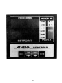
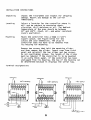
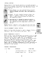
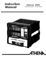
Instruction
Manual
Athena 6050
Temperature Controllers
-THENIL
INSTRUCTION MANUAL
ATHENA 6050
Automatic Tuning
Temperature Controller
SPECIFICATIONS:
Inputs:
Line Voltage
120/240 Vac +lO%, -15%, 50, 60 Hz
Sensor
Thermocouple
Power Consumption
Less than 6 VA (Instrument)
Ranges Available
J Couple 0-1400°F (O-760°C)
K Couple 0-2500°F (O-137O°C)
Accuracy:
0.2% of full scale
Temperature Stability
5 m V/°C Max 3m V/°C typ.
Cold end tracking
0.05°C/°C ambient
Operating ambient for
rated accuracy
0 to 55°C
Maximum T/C lead
resistance for
rated accuracy
100 Ohm
Series mode noise
rejection:
80 dB
Common mode noise
rejection
120 dB
T/C break protection:
Upscale standard
Dual display:
Process temperature displayed
continuously; set point or other
parameters updated on lower display.
1
Display update rate:
5 times per second
Filtering:
Analog and digital filtering
techniques increase stability
of process and display.
°F/°C:
Internal switch selection-process, set point.
output:
Heating only
-B Relay (time
proportioning)
SPST relay 7 Amps resistive at
120 Vac, 5 amp resistive at 240 Vac,
50 VA inductive.
-F Current
proportional
-S Pulsed voltage
-T Triac time
proportional
4-20mADC into 500 Ohm max. For driving
SCR power controllers.
20 Vdc pulsed time proportioning
signal for driving solid state relays.
Solid state plug-in triac output.
Rated 1 Amp holding & 10 amps inrush.
Filtered LED display:
4 digits for process, 4 digits for
parameters.
T/C linearization:
Continuously calculated and updated
using rom based algorithm.
Connections:
Inputs and outputs via barrier strips
with U.L. approved locking terminals.
Dimensions:
Front
Case:
Depth
minus
Mounting:
Channel slides and screws
Weight:
2 lb
2
panel: 96mm X 96mm X 22mm
92mm X 92mm X 118mm
behind panel: 96mm (approx.
panel thickness)
3
FRONT PANEL AOJUSTMENTS
Touch Key
1 Index: Allows the following adjustments to be selected.
1) Set point temperature
O-14OO'F (760°C)
O-2500°F (O-137O°C)
2) Heat cycle time
*1 to 120 seconds
3) Prop. Band (indicated
as gain)
0.25-25% of span
4) Rate with tracking reset
**4-255 seconds
5) Auto Tune (AT)
Up/Down keys: increases/decreases values of above
adjustments.
Tune/Cancel: "cancel" puts output on stand-by to
permit set-up
"tune" triggers automatic tuning procedure
E Enter: writes selected value to nonvolatile memory
NOTES: *setting to zero initiates 60 millisecond timebase
for ultra fast cycling. Use with external solid
state relays or SCR Power Controllers.
**Setting to zero disables reset and rate action
for proportional only control. Reset is six times
higher than rate
FOR OPTIMUM RESULTS WITH THE AUTO-TUNE MODEL 6050
1. Set point must be a minimum of 100°F above ambient for
proper start-up.
2. Multi-zone applications require auto-tune units on each
zone and simultaneous warm-up.
4
3. Loss of power or turn-off during warm-up requires a
re-start from ambient.
4. Change of state processes, i.e. solid to liquid or
liquid to gas, may introduce erroneous tuning parameters
during process warm-up.
GENERAL
1. Accurately measures, linearizes and displays temperature
in °F and °C.
2. Automatically calculates and displays parameters-heat
gain, and rate/reset time.
3. Can be field converted from relay output "B", to solid
state relay “T", to solid state driver "S" or to
a 4-20 MA output SCR driver "F".
4. Will remember its "entered" settings after power failure
or shut-off and not "Go To Sleep".
CAUTION: HIGH VOLTAGE AN0 HIGH TEMPERATURES CAN CAUSE INJURY
AN0 ARE A FIRE HAZARO. PLEASE REAO ALL INSTRUCTIONS, HAVE
ONLY SKILLED PROFESSIONALS WIRE THE UNIT, AND USE APPROVED
TEMPERATURE AND/OR PRESSURE SAFETY CONTROL. EVEN THE BEST
COMPONENTS CAN BE DAMAGED OR MAY NOT FAIL SAFE.
CONFIGURATION
Depending on the model number of the unit you have ordered,
vou will find one of four basic modules installed. The fifth
digit of the code indicate the output module type.
B - Relay 7A/5A @ 120/240 Vac
F - 4-20 mA (Proportional)
T - Triac 1 Amp @ 240 Vac
S - 20 VDC Pulsed for driving solid state relays
Example: 6050-F has proportional 4 to 20 mA heat
output.
Note: If you have not received your controller from the
factory direct, check to confirm that the correct module for
your application is installed. Since the modules plug-in,
and since controller plug into cases as well, previous users
may have changed modules, which can result in severe
controller damage.
5
Output Modules
The Athena 6050 offers users field interchangeable output
modules. This unique feature makes it possible to fill
output requirements for a variety of applications with
a single controller model.
Module Type B: This 7A/5A relay (at 120/240 Vac) is used for
driving resistive heaters.
NOTE: Do not use this output module with mechanical
contactors because they generate an excessive EM1
field which can interfere the 6050's microprocessor.
Instead we recommend "T" output modules for this
application.
Module Type F: This 4-20 mA output module can deliver
full output to loads having an input
impedance of 500 Ohms or less. The cycle
time setting must be ZERO for smooth
current output.
A push-on terminal is utilized as a
return for ground currents of the milliamp
source. It is connected internally to the
mating lug on the heat sink. To avoid
ground loops, drive floating (ungrounded)
loads or use isolated thermocouples.
Module Type T: This solid state relay is capable of 1 AM?
at 120/240 Vac. It is zero voltage switched
and optically isolated from the drive signal.
With it, resistive loads up to 120 watts at
at 120 Vac and 240 watts at 240 Vac may be
controlled directly. Using direct control
there is no lower limit on the cycle time
setting (down to 60 milliseconds). Larger
loads may be controlled utilizing an external
contactor. In this case, it is advisable to use
cycle settings of ten seconds or greater to
minimize contactor wear. External suppression
of the contactor is mandatory.
Module Type S: Similar to F, but pulsed 2OV/2OmA DC output
for driving solid state relays. Up to 6
(input series connected) solid state relays
can be used. Cycle time can be set to optimize
the load response time requirements without
sacrificing S.S.R. life.
7
INTERNAL SWITCHES
Damping Control -To allow the controller to provide automatic
tuning for processes with varying heating characteristics and
with varying heating capabilities, the 6050 offers three
damping choices:
High damping: for over-powered heating systems,
systems with multiple heat lags, and/or poor
coupling between the heater and the temperature
sensor.
Normal: for most standard processes where the
heater is properly sized for the system and
there is good coupling between the heater and
the temperature sensor.
Low damping: for adequately powered systems
with excellent coupling between the heater and
the temperature sensor where quick response and
the tightest possible temperature control are
desired.
Keypad Security -Switch 2 in the open position locks the
operator out of access to all parameters except set point.
CELSIUS/FAHRENHEIT DISPLAY SECTION
Switch 1 allows both displays to read in degrees Celsius or
Fahrenheit, and is indicated on front panel LED's.
WIRING THERMOCOUPLE CIRCUITS
Before wiring, check thermocouple and extension wire to make
sure that they conform to the appropriate thermocouple type
specified on the serial number tag. In thermocouple
circuits, the negative lead is colored red. Extension wires
must be the same alloy and polarity as the couple. The
thermocouple circuit resistance should not exceed 100 OHMS.
Do not run thermocouple leads in the same conduit as the
power lines. If shielded thermocouple is used, terminate the
shield only at the controller end using the corner screw
provided for that purpose.
STANDARD THERMOCOUPLES
I.S.A. TYPE
MATERIALS
COLOR CODE
J
Iron Constantan (I/C)
White(+) Red(-)
K
Chrome1 Alumel (C/A)
Yellow(+) Red(-)
8
THERMOCOUPLE PLACEMENT
Proper thermocouple placement can eliminate many problems in
the system. The probe should be placed so that it can detect
any temperature change with minimal thermal lag. In a process
that requires fairly constant heat output, the probe should
be placed close to the heater. In processes where the heat
demand is variable, the probe should be close to the work
area. Some experimenting with probe location is often needed
to find its optimum position.
In a bath process, addition of a stirrer will help to
eliminate thermal lags. Since the thermocouple is basically
a point measuring device, putting more than onethermocouple
in parallel will provide an average temperature reading and
produce better results in air heated processes.
NOTE: If controls with "F" or "S" outputs drive loads with
grounded or hot input terminals (not floating), an isolated
thermocouple must be used. Otherwise, when both input and
output are grounded, ground loop currents will result,
causing errors and controller damage.
Standard thermocouple limits of error are 4°F or 0.75% of
sensed temperature (half that for special) plus drift caused
by improper protection or overtemperature. This is far
greater than controller error, and can not be corrected at
the sensor except by selection and replacement.
Start-Up
Before line voltage is applied, double-check the following:
Make sure the thermocouple type is correct, and
properly connected (see section on thermocouples)
to terminals 1 and 2 (red on 2).
Make sure there is no AC or DC voltage leading or
arcing to T/C.
Make sure the proper terminals are selected for
line voltage. (8 & 9 for 12OV, 8 & 10 for 24OV)
Check to assure there are no heater shorts, or
shorts to ground, and no bare wires or frayed insulation.
Make sure correct plug-in module is used.
9
OPERATING INSTRUCTIONS
How to Start the automatic tuning procedure
STEP 1: Energize the unit and proceed immediately to step 2.
STEP 2: Place the unit on standby by holding the "Index"
button until the "Autotune" LED lights then press
the Cancel button.
The unit is now ready for set point and cycle time entry.
STEP 3: To enter a set point: A) Hold "Index" button until
the SP LED lights and B) Use the appropriate touch
key, either up or down to enter set point.
When you've entered the desired set point, simply
press the enter key. NOTE: Set point must be at
least 100°F above ambient.
STEP 4: Set cycle time by advancing "Index" to "HC" and
select desired value using up or down keys. Cycle
time is shown in seconds, from 1-120. Setting zero
initiates a 60 millisecond cycle time for ultra fast
cycling for use with "F" or "S" output modules. For
mechanical relays or contactors use l0-120 seconds.
When you've found the desired cycle time press the
enter key.
STEP 5: To start warm up and calculate all PID parameters
advance Index to auto tune again and press the
"tune" button.
The "AT" L.E.D. will light and "HT" L.E.D. will
light. You may now index to any parameter for
viewing as process heats. Upon completion of
tuning, the "AT" L.E.D. will be off.
NOTE: The parameters that the 6050 calculates automatically
can be entered on the Athena 6000/6200 to achieve the
same smooth and precise temperature control on your
process.
10
How to override automatic tuning parameters
It is possible to set or fine tune three mode parameters
manually on the 6050.
To manually enter parameters:
1) Press "Index" button until the LED for the desired
parameter lights.
2) Enter the new parameter using the up or down key.
3) Press the "enter" button.
The new parameters will now take control of the process.
To calculate the PID parameters without using the automatic
tuning mode, consult the Athena 6000/6200 instruction manual.
Reading automatically calculated PID parameters
Press the "index" key. The LED‘s in the "Index" display will
light in sequence, and as they change, the lower digital
display will show each parameter.
11
TROUBLE SHOOTING
Front dark - no instrument power.
Process display shows CCCC - Open thermcouple. Short
terminals 1 and 2. Process display should indicate
temperature at back of case. Repair or replace thermocouple.
About Half or Twice Expected Reading - Check position of
°C/°F switch. Short 1 and 2 to read room temperature. 22-30
is °C, 70-85 is °F.
About 30% Error - Wrong thermocouple type.
Disconnect couple. "J" units over range above 14OO°F, "K"
above 2500°F.
No Heat - No heater power, heater wiring, wrong output module.
Heat Stays On - Welded relay contacts, shorted output module,
or shorted power handler.
Process Display Shows OOOO Or Initially Displays Room
Temperature Then Counts Down Scale As Process Warns - Check
for reversed thermocouple.
Display blinks, entered values change - Caused by electromagnetic
interference (EMI). Supress arcing contacts in system to
eliminate high voltage spikes, seperate sensor and controller
power wiring from "dirty" power lines. Ground heated devices.
Unit Repairs
It is recommended that units requiring service be returned
to an authorized service center. When a controller is
returned for service, a note stating the problem should
accompany the unit.
NOTE: Warranty is void when units are modified by the
customer or other non-authorized parties.
A spare parts list can be supplied upon request if complete
model number, serial number and temperature range is supplied.
12
WARRANTY
This equipment is warranted to be free from defects of
material and workmanship. It is sold subject to our mutual
agreement that the liability of Athena Controls, Inc. is to
replace and/or repair at its factory, provided the equipment
is returned, transportation prepaid within (2) years of its
purchase.
The purchaser agrees that Athena Controls, Inc. shall assume
no liability for consequential damages resulting
from its
use or packaging of shipments returned to the factory.
Components which wear or which are damaged by misuses are
not warranted. These include contact points, fuses, triacs,
and modules. Units which have been modified by customer are
not warranted.
Specifications are subject to change without notice.
13
dTHENd
Controls, Inc., 5145 Campus Drive
Plymouth Meeting, PA 19462 (215) 828-2490