1
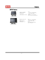
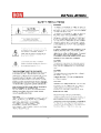
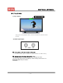
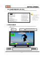
Operating Instructions
HD Digital Monitor
(LCD Multi Format)
Model
BXM-170LS(17”)
BXM-240LS(24”)
Products
B X M Series
•
•
•
•
Resolution 1366X768
Aspect ratio 16:9
Contrast 900:1
Viewing Angle:176 ˚(178 ˚ )
BXM-170LS
• I nput :
SDI (2EA,BNC), Analog(5EA,BNC),
Y/C, DVI , HDMI , PC-RGB
• Output :
SDI (1EA,BNC), Analog(5EA,BNC)
• Power : 12V DC(11V~17V)/AC100-230V
( 17 Inch HD LCD Monitor )
사진
•
•
•
•
Resolution 1920 X 1200
Aspect ratio 16:10
Contrast 1000:1
Viewing Angle : 178 ˚
BXM-240LS
( 24 Inch HD LCD Monitor )
-- 2 --
• I nput :
SDI (2EA,BNC), Analog(5EA,BNC),
Y/C, DVI, HDMI, PC-RGB
• Output :
SDI (1EA,BNC), Analog(5EA,BNC)
• Power : AC100-230V
Multi Format LCD Monitor
-- 3 --
Multi Format LCD Monitor
-- 4 --
Multi Format LCD Monitor
-- 5 --
Multi Format LCD Monitor
-- 6 --
Contents
Thank you for purchasing this product, please read this instructions carefully and save this
manual for later use
Contents
1. Outline • • • • • • • • • • • • • • • • • • • • • • • • • • • • • • • • • • • 8
2. Function and Features • • • • • • • • • • • • • • • • • • • • • • • • • • • • • • • • 8
3. Controls and Functions • • • • • • • • • • • • • • • • • • • • • • • • • • • • • • • 9
3-1. Front Panel• • • • • • • • • • • • • • • • • • • • • • • • • • • • • • • • • • 9
3-2. Rear Panel • • • • • • • • • • • • • • • • • • • • • • • • • • • • • • • • • 11
3-3. Tally & Audio • • • • • • • • • • • • • • • • • • • • • • • • • • • • • • • 13
3-4. Function buttons for F1~F4 • • • • • • • • • • • • • • • • • • • • • • 14
4. STATUS Display • • • • • • • • • • • • • • • • • • • • • • • • • • • • • • • • • 14
5. I NPUT Select • • • • • • • • • • • • • • • • • • • • • • • • • • • • • • • 15
6. OSD Menu Setup • • • • • • • • • • • • • • • • • • • • • • • • • • • • • • • • 16
6-1. Video Setup• • • • • • • • • • • • • • • • • • • • • • • • • • • • • 16
6 -2 . D i sp l a y Set u p • • • • • • • • • • • • • • • • • • • 1 7
6-3. Color Setup • • • • • • • • • • • • • • • • • • • • • • • • • 19
6-4. MARKER Setup• • • • • • • • • • • • • • • • • • • • • • • • • • • • • • 19
6-5. OSD Setup• • • • • • • • • • • • • • • • • • • • • • • • • • • • • 19
6-6. AUDI O Setup• • • • • • • • • • • • • • • • • • • • • • • • • • • • • 20
6-7. GPI PORT Setup• • • • • • • • • • • • • • • • • • • • • • • • • • • • • 21
6-8. SYSTEM Setup• • • • • • • • • • • • • • • • • • • • • • • • • • • • • 21
7.Remote Terminal Assignment • • • • • • • • • • • • • • • • • • • • • • • 22
7-1. Remote Terminal(RJ-45) Assignment • • • • • • • • • • • • • • • • • 22
7-2. GPI Port(RJ-45) Setup • • • • • • • • • • • • • • • • • • 22
7-3. Remote Terminal Assignment • • • • • • • • • • • • • • • • • • 23
8. Program Update Port(RJ-11)Setup • • • • • • • • • • • • • • • • • 24
8-1. Mult i Monit or Cont r ol • • • • • • • • • • • • • • • • • 24
9. Progr am Updat e Port (USB) • • • • • • • • • • • • • • • • • • 25
10. List of Compatible Signal Formats• • • • • • • • • • • • • • • • • • • • 26
10-1. Video Signals : BXM Series • • • • • • • • • • • • • • • • 26
10-2. Computer signals (PC-RGB/DVI ) • • • • • • • • • • • • • • • • 27
11. Specifications • • • • • • • • • • • • • • • • • • • • • • • • • • • • • • • 28
12. DI MENSI ONS • • • • • • • • • • • • • • • • • • • • • • • • • 29
1 3 . T r ou bl e sh oot i n g • • • • • • • • • • • • • • • • • 3 0
1 4 . M a i n t e n a n ce • • • • • • • • • • • • • • • • • • • 3 0
1 5 . Up V er si on an d Modi fi cat i on of Pr odu ct • • • • • • • • 30
-- 7 --
Products Outline & Features
1. Product Outline
BON HD Digital Monitor series are a Multi-Format HD Monitors with high core technology to display
various kind of digital video input signals. It supports HD/SD-SDI, Composite/YC/YPbPr/RGB/DVI/PCRGB/HDMI(HDCP) Signals.
2. Functions and Features
•
•
•
•
•
•
•
•
•
•
•
•
•
•
•
•
•
•
•
•
•
•
•
•
•
•
•
2ch HD/SD-SDI I nputs(2K Format) & 1ch Selective Through output
HDMI (HDCP) input
Analog Component & DVI – I input
2ch Composite input
12bit fully Signal Processor
Pixel Zoom (*2, *4, *8)
Precision 8~16ch Audio Level Meter
Various Markers Display (EBU, Variable)
Precision Monitoring (H/V Delay, R, G, B, Mono)
Closed Caption (608(ANC), 608(Line21), 708)Display
Time Code Display (VI TC)
I nput mode & Signal Status I nformation Display
Waveform Monitoring Display (Y, Pb, Pr Selected, Line Selected)
Video Range Check Display
Vector Display (75% / 100%)
Remote GPI control (RJ-45)
USB Port (Update)
RS-422, Serial Control Port, (RJ-11)
Built-I n Speaker
3 Color TALLY Lamp
Analog Audio I nput/ De-embedded Output
Wide Viewing Angle
UMD/I MD Mode
Teletext (Option)
Lock Type of Esay Picture Adjustment
Hard Coating & Anti Glare Panel & ND Filter (Option)
Rack & VESA Mount 대응 (Rack Mount Option)
!
Please r efer t o Specificat ion Sheet for Det ailed informat ion.
-- 8 --
Multi Format LCD Monitor
3. Controls and Functions
3.1. Front Panel
②
①
⑤
⑥
③
④
⑦
⑧
⑨
⑩
⑪
⑫
⑭
⑬
BXM Front Buttons
①
STANDBY
Power ON/OFF Button. This Button is operated after being pressed about 3 seconds.
②
SDI 1, SDI 2 I NPUT SELECT :
This is for selecting SDI Input. Additional OSD LOGO is displayed.
③ CVBS 1, CVBS 2, YC I NPUT SELECT
This is for selecting CVBS1,2, Input and selecting YC Input. Each time user press this button, it
converts CVBS1,2, Y,C Mode.
④ SCAN
This Button is used to convert output picture status into Zero Scan, Under Scan, Over Scan, Zoom,
Pixel to Pixel Mode. Each time user press this button, it converts above Mode.. (SCAN LED is
ON when Over Scan.)
⑤ DVI
/ VGA I NPUT SELECT
This is for selecting DVI / VGA Input. Each time user press this button, it converts DVI, VGA Mode.
⑥ HDMI
I NPUT SELECT
This is for Selecting HDMI input.
⑦ COMPONENT-YUV, RGB I NPUT SELECT
This is for selecting Components Input. Each time user press this button, it converts YPbPr, RGB
Mode.
⑧ W -FORM/ VECTOR(▼)
Input signal is shown as a format of Wave form or Vector Scope. Each time this button is pressed,
it converts each mode. (This mode is available only in follow mode => SDI, CVBS, S-Video,
YPbPr Mode)
-- 9 --
Multi Format LCD Monitor
⑨ FUNCTI ON 1 (F1, F2, F3, F4)
These two Function buttons carries out the item selected in the SYSTEM Menu.
⑩ MENU
When selected this button, OSD Menu is activated. Please refer to category 6.
⑪ ENTER , ⑪* ENTER/STATUS
1) When sets the OSD Menu used as Enter button. Please refer to category 6 for detailed
information.
2) If the OSD Menu is not activated used for the input signal’s information display.
⑫ R. G. B. GRAY(▲)
1) When this button is pressed, Display Color is shown as a format of Wave form or Vector Scope.
Each time this button is pressed, it converts each mode.
These functions are available only in SDI, CVBS, S-Video, Y Pb Pr mode
2) When the OSD MENU is activated, used for Up (▲) button
⑬ MARKER(▼)
1) Used for Marker On/Off.
2) When the OSD MENU is activated used for down(▼) button.
⑭ ADJUST
Possible to control these functions .(Brightness, Contrast, Saturation, Phase, Volume)
Brightness
Contrast
Chroma
Phase
Speaker Volume
!
Selectable these items
When the OSD MENU is activated this VOLUME button can be used for Up(▲),
Down(▼) and ENTER.
-- 10 --
Multi Format LCD Monitor
3.2. Rear Panel
1. USB 2. RJ-45(GPI) 3. RJ-11 x 2 4. earphone
Rear of BXM
-- 11 --
Multi Format LCD Monitor
①: USB Updat e Por t
You can update Firmware by this USB port. Please refer to category7 for detailed information.
② : REMOTE Por t ,RJ-45 Jack – Thr ough (RJ-45) Por t
Terminal for controlling the monitor by an external control. (Make/Trig Type)
Please refer to cagegory8 for detailed information.
③:
UPDATE Por t (RJ-11 Jack )
Serial Communication Port
This port is used to modify monitor program or to control Monitor.
Please refer to category for detailed information.
④ : AUDIO IN/OUT
Input/Output terminal for the external Audio and Embedded Audio Signal.
⑤ : SDI 1 , SDI 2 input .
⑥ : LOOP OUT j ack (Select ed Act ive Thr u out )
⑦: Component input
Y,U,V (Y,Pb,Pr) and R,G,B
⑧: Component LOOP OUT
Component Loop Out port
To set Component Loop Out, set Analogue Loop into “ON” in the MENU/VI DEO
⑨: Composit e /
Y/ C(S-Video) I nput
⑩: Composit e LOOP OUT
Composite Loop Out port
To set Composite Loop Out, set Analogue Loop into “ON” in the MENU/VI DEO
⑪: DVI -I
input j ack
⑫: HDMI
input j ack
⑬: PLD Updat e Por t
Used for PLD Update port.
⑭ : AC I NPUT (AC 100V~220V)
-- 12 --
Multi Format LCD Monitor
3-3. Tally & Audio
1) Tally Display
Tally Lamp
Tally Colors are 2types(Red, Green), and can be selected by external contact
terminal.
2) AUDIO Input/Output
①
Analog Audio L/ R t er minal (St er eo Pin Jack )
The external audio signal is available through the speaker by a Menu setting.
②
Analog Audio L/ R Output (St er eo Pin Jack)
Terminal for output of De-embedded Analog Audio signal from SDI.
The 16ch Audio Signal output is available by a Menu Setting. Please refer to 6-6
Embedded Audio Setup for detailed
information.
-- 13 --
Multi Format LCD Monitor
3-4. Function Button for F1, F2, F3, F4
Used to select the functions to be assigned to individual buttons F1 ~F4(front-panel buttons).
Function
1. PC SCAN Aspect/Fill
2. Aspect Native/16:9
3. Pixel to Pixel On/Off
4. Anamorphic On/Off
5. PaP On/Off
6. PiP On/Off
7. Fast Mode On/Off
8. Time Code Display On/Off
9. Marker On/Off
10. Caption Display On/Off
11. Audio Display On/Off
12. Audio Mute On/Off
13. H/V Delay On/Off
14. Freeze Main On/Off
15. Freeze sub On/Off
16. Front Button LED On/Off
17. Video Loss Tally
18. Video Loss Alarm
19. Video Range Check
20. Focus Peaking Display
!
H/V Delay is available only
below mode.
1) SDI -1, SDI -2 input
2) CVBS1, CVBS2 input
3) S-Video
4) YPbPr, RGB input
4. STATUS DISPLAY
Used to confirm the operating status. Some functions are not supported depending on the
installed options. .
Video
Waveform
Display Left
CH-1,3,5 ~ 15
Time Code
Display
Displays selected input signal
format information on the screen
Displays up to 16channels(L/R each 8channels) of audio
level by De-Embedded of HD/SD-SDI’s serial Audio Signal.
-- 14 --
Display Right
CH-2,4,6 ~ 16
Multi Format LCD Monitor
1) Audio Level Display Mode.
You can set Audio Level Display On/Off and display position.
2) Waveform Monitor Display
You can set Waveform Monitor Display On/Off and display position by OSD Menu.
!
Wave form is not available in YPbPr 1080p input.
3) Time Code Display
You can set Time Code display On/Off and display position by OSD Menu.
!
• Time Code Displaying is available SDI input only.
5. INPUT SELECT
< Input Button >
-- 15 --
Menu Setup
6. OSD MENU
6-1. VI DEO Setup
▪ Br ight ness : Adjusts brightness.
▪ Cont r ast : Adjusts Contrast.
▪ Chr oma : Adjusts Chroma.
▪ Phase(Hue): Adjusts Phase.
▪ Shar pness : Adjusts Sharpness.
▪ NTSC Set up : Selectable among 0 IRE,7.5 IRE
VIDEO MENU
7.5 IRE -> -> Operates at NTSC or YUV Mode .
▪ Dithering : sets gradation effect.
ON -> makes screen gradation smooth
(Recommended to turn Dether ON if 8bit output)
Off -> without gradation effect, it outputs into screen
▪ VGA Color Set ▪ VGA Display Set :
Activates only in VGA Input. mode. There are Default
mode and User Adjust Mode.
6-1-1. VGA COLOR setup
This menu is applied VGA input mode only.
▪ Red Gain : Controls Gain of Read input.
▪ Gr een Gain : Controls Gain of Green input.
▪ Blue Gain: Controls Gain of Blue input.
▪ Red Bias ▪ Gr een Bias▪ Blue Bias : Controls offset
of each Bias.
!
VGA Color Set : You can control each value of R.G.B among YPbPr, RGB, VGA input
mode only.
-- 16 --
Menu Setup
6-1-2. VGA Display Setup
This Menu is displayed VGA Mode Only.
▪ V -Posit ion ▪ H -Posit ion : You can adjust V and H
position in PC-RGB input mode.
▪ Phase: You can adjusts Phase
▪ Aut o Adj ust : You can adjust screen position
automatically..
6-2. Display
▪ PC SCAN : You can select display mode among Fill and
Aspect.
▪ Aspect
: Sets picture ratio as 16:9 or as Native
ration in SD mode, 2k mode.
▪ Pix el t o Pix el(1:1) : This function is available only in
7” and 20” model. Displays native signal inputted in HDSDI, 1920 x 1080 without scaling down. The active display
can be set to Left Upper, Right Upper, Left Bottom, Right
Bottom, and Center.
▪ Anamor phic : Makes vertical resize to see Anamorphic screen(2.35:1) on 720/50P 59.94P mode.
▪ Fast Mode : Used select Fast, Normal Mode
Fast mode minimize the delay time as it outputs I nterlaced scanning I nput not converting into
progressive scanning method. Nor mal Mode is used to output I nterlaced scanning signal as
progressive scan.
▪ Back Light : Controls brightness of LCD backlight.
▪ Test Pat t er n : Without additional Input signal, it provides internal Test Pattern of 1920 x1080 30p
format on the screen. (Off, Blue, Green, Red, 0~100% White)
-- 17 --
Menu Setup
6-2-1. Display
Sets Screen size mode or display status.
▪ PIP & PAP Main : Selects input of Main.
▪ PIP & PAP Sub : Selects input of Sub.
▪ Dual Display Type : In the Dual Display Mode, you can
adjusts position and sized of picture.
▪ PiP Position : You can select position of Sub.
▪ W .F Display Mode : Selects W.F display Mode.
▪ W .F Line Select : Display selected line’s W.F and you can select the line by UP ▲ DOWN ▼ button.
▪ W .F Select : Used to display desired Video waveform -> Y(Green), Cr(Red), Cb(Blue)
▪ W .F Posit ion : Used to set the position of Waveform Display -> Left Top, Left Bottom, Right Top, Right
Bottom
▪ Vect or Posit ion : Used to set the position of Vector scope among-> Left Top. Left Bottom. Right Top.
▪ W .F & Vect or Blend : Used to adjust transparency of W.F and Vector scope.
6-2-2. Display Setup
▪ Video Range Check : Video Range Check On/Off
▪ Y Range Max : Used to set Maximum value of Y.
▪ Y Range Min : Used to set Minimum value of Y.
▪ C Range Max : Used to set Maximum value of C.
▪ C Range Min : Used to Set Minimum value of C..
▪ Blink Color : Used to set the Blink Color when the Video Range Check On. There are Black/ Blue/
Green/ Red.
▪ Blink Time : Used to set the Blink time when the Video Range Check ON.
▪ Focus Peaking Display : Camera Focus Assistance On/Off.
▪ Peaking Color : Used to set the peaking color of Focus Assistance.
▪ Peaking Width : Used to set the peaking width of Focus Assistance.
-- 18 --
Menu Setup
6-3. COLOR
▪ Color Temper at ur e
: Sets color temperature on screen among
3200°K,5400°K,6500°K, 9300°K의
▪ Adj ust Temper at ur e
: Activates when User is set in Color Temperature
RGB Gain and Bias are possible to control
▪ R,G,B Gain : Control each R,G, B Gain in USER mode
▪ R,G,B Bias : Control each R,G,B Bias in USER mode
6-4. MARKER
▪ Mark er 16:9
Used to set the type of Marker in 16:9 HD Signal.
-> 4:3,15:9,14:9,13:9,1.85:1,2.35:1,User,Off
▪ Safety Area 16:9
Used to set the safety area in 16: 9 HD signal
-> EBU ACT 16:9/14:9/4:3, EBU GRA 16:9/14:9/4:3,
Off, 80%,85%,88%,90%,93%,95%
▪ Safety Area 4:3
Used to set the safety area in 16:9 HD signal input
-> EBU ACT 16:9/14:9/4:3, EBU GRA 16:9/14:9/4:3,
Off, 80%,85%,88%,90%,93%,95%
▪ Cent er Mark er : Center Marker On/Off
▪ Mark er Color : Selects Marker Color.-> Black, Red, Green, Blue, White, Gray
▪ Mark er Thick ness : Set Marker Thickness as Pixel unit. (1~10 Pixels)
▪ Mark er Back Color : Sets background transparency between Normal and Half, excluding
Safety area. -> Normal, Half
▪ User Mar k er H1,2/ V1,2 : Sets H,V Position of User Marker
(Depending on inch, user can be set the maximum resolution which are supported in the LCD Panel.)
6-5. OSD
▪ Timecode Display : Timecode Display ON/OFF
▪ Timecode Posit ion : Used to set position of Time
Code.
▪ Menu Display Time : Sets Menu and
Information.
-> Select one of off, 0(continute)~60
seconds.
▪ Menu Blend : Set transparency of menus and
indication windows on the screen
-> Selects 0~15 levels
-- 19 --
Menu Setup
▪ MENU Posit ion : Select for Center, Left Top, Right Top, Left Bottom, Right Bottom.
▪ Closed Capt ion : This function is available in Composite, YPbPr,l and Digital(HD/SD-SDI) signal. There
are three selectable mode : OFF, CC 708, CC 608 (Transcoded, VANC, Line 21 Line), . This function
displays character information included in CC signal on the screen..
▪ CC608 St ar t Line : Used to set the start line of CC608 on screen In 608 Sine 21 Mode,
Menu Posit ion: Left-Top, Left-Bottom, Right-Top, Right-Bottom, Center
Closed Capt ion Display : Standard 608(CVBS & SDI : NTSC/PAL)
Digital 708(SD/HD-SDI )
6-6. AUDI O
▪ Play Channel (L)
Designates extracted sound signal from Speaker
Source into Left Output Channel.
▪ Play Channel (R)
Designates extracted sound signal from Speaker Source
into Right Output Channel .
▪ Audio Level Met er : Displays the level of inputted
Audio signal as Level Bar on the screen .
▪ Level Met er Posit ion : Selects the position of Audio
Level Meter either Upper or Lower.
▪ Speak er Sour ce : Selects Speaker Output among Auto / SDI 1,2 / LI NE I N input
▪ Speak er Volume : Sets Speaker Output Level.
-- 20 --
Menu Setup
6-7. GPI PORT Setup
▪ GPI Cont r ol :
Used to select external control terminal ON/OFF. I t is
not possible to control through Remote terminal from
outside or external area when it is OFF
▪ GPI Por t 1,2,3,4,5,6,7
Used to select each terminal of external Remote
Control Terminal (RJ-45).
However, GPI Port7 is fixed as Key Standby. For detailed
information, please refer to category 8-1,2,3
▪ Remot e I D Number : Used to set own number for monitor in case I R remote Control (Option)
▪ Ser ial Remot e : Select whether use external Serial Port control or not.
I f Ser ial Remot e is on, I R remot e contr oller and Key do not w or k
To terminate Serial Remote Status (Update, Remote On), press Menu button for 3
seconds.
!
6-8. SYSTEM
▪ Funct ion 1,2,3,4 : Used to select the functions to be
assigned to individual buttons to F1, F2, F3, F4
(For detailed information, please refer to category 3-4)
▪ Fr ont But t on Lock : Sets ON/OFF lock function of
front key buttons.
▪ Setup Load : used to change product setup status.
- Factory Mode: used to return to the factory default.
- User 1,2,3 Mode : Menu Setting is transferred to the
Menu of 1,2,3 to be saved by user
▪ Set up Load : Used to change Setup.
- Fact or y Mode: Used to return to factory default.
- User 1,2,3 mode : Menu Setting is transferred to the Menu of 1,2,3 to be saved by user.
▪ Set up Save : Used to save current Menu setting. User 1,2,3 can be used by Setup Load.
▪ Fir mw ar e Ver sion : Displays F/W Version and H/W Version.
▪ Oper at ing Time : Displays operating time of the product.
!
Not e) W hile Back Light is adj ust ed, LCD panel r equir es enough t ime t o be
st able adj ust ing Phase (br ight ness). I t r equires mor e t han 30 minut es.
-- 21 --
Multi Format LCD Monitor
7. Remot e Ter minal Assignment
7-1. Remot e Ter minal(RJ-45) Assignment
Each terminal function can be set from the GPI CONTROL SETUP Menu.
1 2 3 4 5 6 7 8
Remote (RJ-45)
Remot e PI N Assignment
1 PI N
GPI Port 1
5 PI N
GPI Port 5
2 PI N
GPI Port 2
6 PI N
GPI Port 6
3 PI N
GPI Port 3
7 PI N
GPI Port 7(Stand by Power
ON/OFF) Fixed
4 PI N
GPI Port 4
8 PI N
COMMON(GND)
7-2. GPI Por t(RJ-11) Connection
Control Terminal : 1 ~ 7 Pin
Contact Point Switch.
I t is possible to attach
pin one by one.
GND Terminal : 8 Pin of RJ-45
!
Please refer to category.7-3. Remote Terminal Assignment.
-- 22 --
Multi Format LCD Monitor
7-3. Remote Terminal Assignment
Port Assignment I tems
CVBS1 I nput
CVBS2 I nput
CVBS3 I nput
SDI 1 I nput
SDI 2 I nput
DVI I nput
HDMI I nput
VGA I nput
Y/Pb/Pr I nput
R/G/B I nput
S-Video I nput
Gray Only
Blue Only
Under Scan
Over Scan
Zoom Scan
Key Up
Key Down
Key Menu
Key Enter
PC Scan
Aspect Ratio
Pixel to Pixel
Anamorphic
PaP
PiP
Waveform Display
Time Code Display
Vector Display
Dual Link Mode
Fast Mode
Marker Display
Marker 16:9
Safety Area 16:9
Safety Area 4:3
Center Marker
Caption Display
Audio Display
Audio Mute
Tally Red
Tally Green
H/V Delay
Freeze Main
Freeze Sub
Front Button LED
Function
Switches the input CVBS1
Switches the input CVBS2
Switches the input CVBS3
Switches the input SDI -1
Switches the input SDI -2
Switches the input DVI
Switches the input HDMI
Switches the input PC-RGB
Switches the input YUV
Switches the input RGB
Switches the input Y/C
Switches Mono ON/OFF.
Switches Blue Only ON/OFF.
Scales down the screen.
Scale Up the screen.
Fits the screen into inputted definition.
Cursor Up during Menu Control
Cursor Down during Menu Control.
Switches Menu Functions ON/OFF.
Switches Enter Button ON/OFF.
Selects Aspect/Fill in PC-RGB Mode.
Operating conditions
Edge operation
Selects Native Ratio/16:9 in SD mode.
Switches Pixel to Pixel Scan Function ON/OFF.
Switches Anamorphic Function ON/OFF
Switches PaP Function on/off.
Switches PiP Function on/off.
Switches Waveform Display ON/OFF.
Switches Time Code Display ON/OFF.
Switches Vector Scope Display ON/OFF.
Selects Dual Link RGB444/YPbPr422/OFF
Selects Fast Mode/ Normal Mode.
Makes Marker APPEAR/DI SAPPEAR.
Controls Marker Area in 16:9
Controls Safety Area in16:9.
Controls Safety Area in 4:3..
Makes Center Marker APPEAR/DI SAPPEAR
Selects Caption Function among Off/608/609.
Switches Audio Level ON/OFF.
Switches Audio Output Mute ON/OFF
Switches Red Color of Tally Lamp ON/OFF.
Switches Green Color of Tally Lamp ON/OFF.
Switches H/V Delay Function ON/OFF.
Stops Main either at PaP or at PiP
Stops Sub either at PaP or PiP.
Switches LED of the Front button ON/OFF.
-- 23 --
Level Operation
(Connected:ON, Open:Off)
Edge operation
Multi Format LCD Monitor
8. Program Updat e Port (RJ-11)
Update Port(RJ-11) can be used in a situation as below.
1) To modify Firmware program
2) To control Color Temperature, Gamma Setting for LCD
3) To control Multi Monitors using PC Exclusive use program “Wall System Control” on PC
Please consult w it h t echnician for Pr ogr am Updat e or for Ser ial Por t
use. I ncorr ect use of t his por t may cause damage or malfunct ion.
!
1 2 3 4 5 6
Update (RJ-11)
1 2 3 4 5 6
Update Terminal Assignment
1 PIN
NC
4 PIN
GND
2 PIN
RX+
5 PIN
TX+
3 PIN
RX-
6 PIN
TX-
.
8-1. Multi Monitor Cont r ol (thr ough Updat e Por t)
Multi Monitor Control can be operated by exclusive use Adaptor(RS-232C < -> Serial Conversion)
Converting device and by PC where exclusive use program (Wall System Controller) is installed.(Option)
A
PC (Control S/W)
BWC-100
Adaptor(RS-232C < -> Serial Data)Converting Device
-- 24 --
Multi Format LCD Monitor
9. Program Updat e Port (USB)
1) Used for Firmware Update.
9-1 How to updat e t he fir mw ar e by USB por t.
Set the Update Execute to Yes, and then, exit the menu by pressing menu button.
Then, it automatically start update procedures.
-Updat e Pr ocess
HOST Updat e : SDI -1, SDI -2 LEDs gradually turn it ON/OFF, and when completed, it starts
Reboot (Approximately 2 minutes required)
VI PER Updat e : LEDs of below front buttons will be turning as following order, and when
completed, it automatically Reboot.
SDI -1 -> SDI -2 -> CVBS1,2/YC -> YPbPr/RGB -> HDMI -> DVI /VGA.
(Approximately 6 minutes required.)
Good ex ample : I n case
proper update file is
located in the inserted
USB
Bad ex ample : I n case
Update file is not located
in the inserted USB or NO
USB inserted into the
monitor
!
1. USB Updat e File must be locat ed in t he pr iorit y folder of USB t o ex ecut e update pr oper ly.
2. USB Updat e Por t support USB st or ages t hat w er e For mat ed by FAT12,FAT16
or FAT32 file syst em ONLY.
3. A few of USB st or ages may not be r ecognized in BXM Monit or .
!
USB Updat e suppor t s HOST/ VI PER Updat e ONLY.
VI PER Updat e should be conduct ed by t he updat e port locat ed in t he
r ear of t he monit or
!
I f Monit or does not r ecognize USB pr oper ly, inser t USB st or age ahead of t ime befor e
Tur n t he monit or ON.
-- 25 --
Multi Format LCD Monitor
10. List of Compat ible Signal for mat s
10-1. Video Signals : BXM Ser ies
NO
I nput Signal
Formats
Component
Composit
e/ SY,Pb,Pr R,G,B
Video
√
√
√
√
√
√
√
√
√
√
Single
√
√
√
√
√
√
HD/SD-SDI
Dual
Dual
YUV4:2:2 YUV4:4:4
√
√
√
√
√
√
Dual
RGB444
√
√
√
√
√
√
DVI /
HDMI
1
2
3
4
5
6
7
9
9
10
NTSC
PAL
525/60i (SD)
625/50i (SD)
720*480/59.94p
720*576/50p
1280*720/23.98p
1280*720/24p
1280*720/50p
1280*720/59.94p
11
12
13
14
15
16
17
18
19
20
21
22
23
24
25
26
1280*720/60p
1920*1035/59.94i
1920*1035/60i
1920*1080/50i
1920*1080/59.94i
1920*1080/60i
1920*1080/23.98p
1920*1080/23.98psf
1920*1080/24p
1920*1080/24psf
1920*1080/25p
1920*1080/25psf
1920*1080/29.97p
1920*1080/29.97psf
1920*1080/30p
1920*1080/30psf
-
√
√
√
√
√
√
√
√
√
√
√
-
-
√
√
√
√
√
√
√
√
√
√
√
√
√
√
√
√
√
√
√
-
√
√
√
√
√
√
√
√
√
√
√
√
√
√
√
√
√
√
√
√
√
√
√
√
√
√
√
√
√
√
√
√
√
√
√
√
√
√
√
√
√
√
√
-
27
1920*1080/50p
-
√
-
-
√
-
-
√
28
29
30
31
32
33
34
35
36
37
1920*1080/59.94p
1920*1080/60p
2048*1080/23.98p
2048*1080/23.98psf
2048*1080/24p
2048*1080/24psf
2048*1080/25p
2048*1080/25psf
2048*1080/29.97p
2048*1080/30p
-
√
√
-
-
√
√
√
√
√
√
√
√
√
√
-
-
√
√
√
√
√
√
√
√
√
√
-
• With Analog YPbPr mode, 1035/59.94i,60i signal input, Marker is displayed in
1080/59.94i,60i and output.
• Output screen mode can be output with automatic control in DVI mode.
• STATUS Display of I nput Signal might be different with real screen.
• Safety Area Edge part may not be displayed in some modes.
-- 26 --
√
√
√
√
√
√
Multi Format LCD Monitor
10-2. Comput er signals (PC-RGB/ DVI ) : BDM Ser ies
NO
I nput Signal
Names
Screen Resolution
VGA
(PC-RGB)
DVI
Vertical Frequency
1
VGA
640*480
√
√
60Hz ~ 100Hz
2
SVGA
800*600
√
√
56Hz ~ 85Hz
3
XGA
1024*768
WXGA
1280*768
√
√
86Hz ~ 100Hz
4
√
√
5
SXGA
1280*1024
√
√
60Hz ~ 76Hz
6
WSXGA+
1680*1050
√
√
50Hz~60Hz
7
UXGA
1600*1200
WUXGA*
1920*1080
√
√ ,note1
60Hz Only
8
√
√
9
WUXGA
1920*1200
-
√ ,note1
60Hz,( PC Only)
50Hz ~ 85Hz
60Hz
• Output resolution could be changed automatically according to PC Graphic Card in
PC-RGB and DVI I nput mode.
-- 27 --
Specifications
11. Specificat ions
Section
Input
Output
Analog Input
Level
SDI Input
Analog Input
DVI-RGB Input
DVI Input
HDMI
SDI Output
Analog Output
Composite
YC(S-Video)
Component(Y/Pb/Pr)
Component(R/G/B)
DVI-RGB,Sync Level
2K Format
Dual_YUV422
Dual_YUV444,
Dual_RGB444
SMPTE 274M
SMPTE 296M
SMPTE 372M
SMPTE 260M
SMPTE 259M,125M
ITU R-BT.656
Component
HDMI Digital
DVI Digital
DVI-RGB Mode
Input Line
Audio Input
SDI Audio Input
Output Line
Speaker Output
Audio Output
Ear-phone Output
Output Signal
Remote
I/O Port
Update
Size
Resolution
Pixel Pitch
Color
LCD
Viewing Angle(deg)
Luminance of White
Contrast
Display Area (H * V)
Power Requirements
Power Consumption(Approx)
Operating Temperature
Operating Humidity
Weight (without Stand & Packing)
Dimension(W*H*D)without Box&Stand
Digital Input
Fomat
Accessory
Option
BXM-170
BXM-240
2EA, HD/SD Serial Digital , 1.485G/270M, BNC Jack
2EA, Composite,YC(S-Video),3EA Component,RGB,BNC Jack
1EA, DVI + Analog Jack (with gender) (24Pin + 5Pin)
1EA, DVI-I, 24pin, Female
1EA, HDMI, 19pin Female
1EA, BNC, Selective SDI-Active Loop Output
5EA, 75Ω,Analog Loop,BNC Jack
1.0Vp-p(with sync), NTSC/PAL
Y :1.0Vp-p, C:0.286Vp-p
Y :1.0Vp-p, Pb :0.7Vp-p, Pr :0.7Vp-p
G :1.0Vp-p(with Sync), B :0.7Vp-p, R :0.7Vp-p
R, G, B : 0.7Vp-p, H/V Sync : 4V ± 1Vp-p
2048*1080/24p, 23.98p, 24psf, 23.98psf
1920*1080p/60, 59.94, 50
1920*1080i(60, 59.94, 50),1080p(30, 29.97, 24, 23.98),
1280*720p(60, 59.94, 50)
1920*1080i/60, 59.94, 50
1920*1080p/30, 29.97, 25, 24, 23.98, 23.98sf
1280*720p/60, 59.94, 50
1920*1035i/60, 59.94
720*480i/60, 59.94
720*576i/50
640 * 480 up to 1920 * 1080p
~ 1920 * 1200(embedded Audio,w/o HDCP)
640 * 480 up to 1920 * 1200
640 * 480 up to 1280 * 1024, max 1600 * 1200
1EA, L/R Stereo, RCA Jack
Embedded HD/SD-SDI Audio
1EA, L/R Stereo, RCA Jack
2EA, 2W+2W
1EA, L/R Stereo, 3.5mm pin jack
Input Line & De-embedded Audio, 1 ~ 16CH
1EA, Remote, RJ-45P Jack, GPI-7 Port
2EA, RJ-11P Jack, RS-422, Serial interface
17”(LC171WXN-SAA1)
24”(LM240WU7-SLB2)
1366 * 768(16:9)
1920 * 1200
0.091*0.273 mm
0.270 mm
16.7M
16.7M
R/L:178, U/D:178
R/L:178 , U/D:178
350 cd/m²
400 cd/m²
900 : 1
1000 : 1
372.91 * 209.66 mm
518.4 * 324 mm
AC100 ~ 230V, 50/60Hz
0.65A ~ 0.34A(??W)
0.65A ~ 0.34A(??W)
0°C ~40°C(32°F~104°F)
20% ~ 80% RH
7.0 kg
9kg
421.6 * 309 * 95.3 mm
436 * 329 * 82.8 mm
•Power Cord
-1• Manual
-1•DVI to VGA Gender -1• Stand
-1•Rack Mount (Option)
• Vertical/Wall Mount (Option)
•ND Filter (17”,24”Option) •Hood & Carring Case (Option)
•V-Mount (8.4”,17” Option)
Specifications can be changeable for the efficiency and quality improvement of this product without prior notice
-- 28 --
Demension
12. DI MENSI ONS
Battery Pack
V-Mount Hole
VESA Mounting Hole
(100*100/75*75mm)
Size M4, Depth 10mm
BXM – 170LS Dimensions (Unit: mm)
VESA Mounting Hole
(100*100)
Size M4, Depth 10mm
BXM - 240LS Dimensions (Unit: mm)
-- 29 --
RMA & Maintenance
13. Trouble shooting
Solutions to common problems related to the monitor are described here.
I f none of the solutions presented here solves the problem, unplug the monitor and consult
an authorized dealer or service center.
NO
1
Symptom
No power supply
Probable cause and corrective action
• Firmly insert the Power Cord.
Check the power. (100V ~220V)
• Connect the signal cable firmly.
Turn on the power of the connected
component and set the output correctly.
Check if the input signal format is
acceptable to the monitor.
• Connect the signal cable firmly.
Adjust Volume Level.
• Check if the Hue is set up with basic value
from the menu.
Check if the color temperature is in basic value.
2
No picture with the power on
3
No sound
4
Wrong color, no color
5
Wrong picture position,
wrong picture size
• Check Pixel to Pixel mode is on.
Adjust the picture size (H/V Position)
Menu do not appear on the
screen or it is shaking
• The items which are not available for the
current input or the current input signal are
not displayed on the menu. Change input or
the input signal.
Check if the input signal format is
acceptable to the monitor.
6
Page
14. Maint enance
▪ When a still video of LCD is displayed for a long time, it may appear wrong image by heating on the screen.
This is due to the characteristics of the LCD display and is not malfunction. After power off for a moment,
start over again.
▪ The red spots, blue spots and green spots on the panel surface are a normal characteristic of LCD displays,
and it is not a problem. The LCD display is built with very high precision technology, however, be aware that a
few very small pixels may be a little troubled by crossing each other or lighting.
▪ Periodic maintenance inspection time of backlight is about 50,000 hours.
▪ Periodic maintenance inspection time of fan motor (option) is about 10,000 hours.
15. Up version and Modificat ion of Product
• Specifications can be changeable for the efficiency and quality improvement of this
product without prior notice.
-- 30 --
Memo
MEMO
BON ELECTRONI CS, I NC.
(Head Office) Tresbelle Sky B/D 2 F, 1479 Gayang2-Dong, Gangseo-Gu,
Seoul, Korea
Tel : (+ 82) 2-2659-0333 (113), fax: (+ 82) 2-2659-8133,
[email protected]
[email protected]
http://www.bon.co.kr
-- 31 --
Printed in Korea 950-203A-R, 08Y 09M