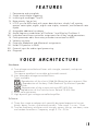
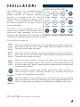
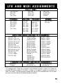
1
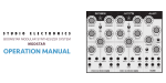
FEATURES / VOICE ARCHITECTURE .............................................................. ii IMPORTANT NOTES .................................................................................... 1 INTRODUCTION ......................................................................................... 2 BASIC OPERATION GETTING IT STARTED................................................................................... 3 CONNECTIONS .......................................................................................... 4 USING THE MEMBRANE AND ROTARY ENCODER (reading the display) ........... 5 CREATING SOUNDS OSCILLATORS ........................................................................................ 6, 7 FILTER ....................................................................................................... 8 ENVELOPES .................................................................................... 9, 10, 11 MODULATION ................................................................................... 12, 12b MIDI-KYBD .......................................................................................... 13, 14 PROGRAM (editing and saving patches) ....................................................... 15 TECHNICAL INFO LFO AND MIDI CONTROLLER ASSIGNMENTS ............................................. 16 MIDI IMPLEMENTATION CHART ................................................................. 17 SPECIFICATIONS ....................................................................................... 18 TROUBLE SHOOTING ................................................................................ 18 I. II. III. IV. V. VI. VII. VIII. IX. X. XI. XII. XIII. XIV. Portamento and auto glide. Single and multiple triggering. Inverting of envelopes 1 and 3. Note priority: low or last. LFO 2 sync to MIDI clock with seven beat divisions: whole, half, quarter, quarter note triplet, eighth, eighth note triplet, sixteenth, and sixteenth note triplet. Assignable additional envelope. Audio frequency modulation of Oscillator 1 and filter by Oscillator 2. Individual continuous controller assignments for all key sound parameters. Patch parameter edits from rotary encoder transmitted via MIDI. Velocity sensitive. Extensive Modwheel and Aftertouch assignments. Holds 512 patches in RAM. External input for audio signal processin g. Ringmod Hardware: A. Two voltage controlled oscillators with triangle, sawtooth, and square waveforms. The square waveform has variable pulse width control. B. User selectable voltage controlled filters. Types available: Reproduction of the classic 24db MiniMoog low pass resonant filter Reproduction of the boxy 12db Oberheim Synthesizer Expander Module filter. Reproduction of the unique and rare ARP 2600 filter Reproduction of the Techno classic Roland TB-303 filter C. White noise generator. D. High dynamic gain voltage controlled amplifier. Software: A. Three four-stage envelopes with specially designed exponential curves. Attack, decay, sustain, and release controls. Time range: 1 m.sec - 15 sec. B. Two low frequency oscillators with triangle, square, saw up, saw down, noise and random waveforms. Frequency range: 0.1 hz - 50 hz In addition to the aforementioned "Safety Instructions" printed on the inside front cover, we (the goodly folks at S. E.) ask––nay, we implore!––you please read and heed the following recommendations: POWER SUPPLY CONCERNS Turn off the power to all equipment before making any connections between devices. This will help to prevent malfunction and likely speaker damage. Be certain to use a separate power outlet for this unit, as sharing one with distortion producing devices (such as motors, variable lighting devices) is unwise. PLACEMENT CONCERNS Placing the unit in close proximity to power amplifiers or equipment containing large transformers is likely to induce hum. If the unit is to be operated nearby T.V. or radio receivers, some type of interference might be noticeable. In such cases, move the unit out of proximity with the entertainment devices. MAINTENANCE In hopes that you might keep the visuals of your treasured analog gem in tip top shape, our cleaning specialists advise wiping ever so gently with a slightly dampened soft cloth. For those stains of a more tenacious temperament add a mild detergent to the mix, always remembering to follow with that ubiquitous "soft dry cloth". Never apply solvents of any kind: benzene, paint thinner, propyl alcohol, etc., to avoid the risk of nasty discoloration, disfigurement and most importantly, those deadly liver flukes. (It should be parenthetically noted that neither solvents nor the unit itself are ever to be taken internally!) OTHER PRECAUTIONS Protect the unit from strong jolts and vibration, especially when standing on well-established fault lines. Never apply strong pressure to the front, back or side panels, or strike them in any manner whatsoever. It is normal and helpful for this synthesizer to generate a certain degree of heat. MEMORY BACKUP CONCERNS Within the unit is contained a battery which serves to maintain the contents of the memory when the power is switched off. The normal life of this battery is 5 years or more. To prevent unintentional memory loss, the battery must be replaced every 5 years as a rule. When it is time to change it, contact us, or your local authorized Studio Electronics service station. Please be aware that the contents of the memory may possibly be lost: when sent for repair work, or when a chance malfunction occurs––it is always prudent to back up your complete memory via a SYSEX bulk dump. Remember, each bank must be saved individually. When in the shop for repair, great care is taken to avoid data loss, however In the event of damage to circuitry related to the memory system itself, you are sorry for Charlie (emphasis Greg’s). Thank you for purchasing the S T UDIO E LECTRONICS ATC- X. You're soon to discover the world's only 4-way discrete multi-filtered analog synthesizer. Like never before, you now have the ability to create and explore all of the classic Analog synthesizer sounds in one powerfully expressive and versatile machine. The ATC- X is a truly modern Analog synthesizer, incorporating authentic discrete component circuitry with complete MIDI implementation and total programmability. Control of the parameters from the optical encoder is smooth and precise. Its creative and intuitive design incorporates unique features and functions, allowing the discerning musician complex tone manipulation and seemingly endless patch variations. The electronically produced sound of the ATC- X is vibrant, warm and "punchy"; possessing the highly pleasing qualities of inherent randomness in pitch and timbre, like those of a fine acoustic instrument. We take great pride in manufacturing this instrument in "the land that the rivers have quartered"––The United States of America and maintain the highest standards of quality by meticulously procuring only the finest materials and carefully assembling each and every S T U D I O E L E C T R O N I C S product by hand. It is our sincerest hope that the long anticipated ATC- X surpasses expectations and provides decades of satisfaction, pleasure and performance. Setting Up the Instrument A. Plug the power supply cable into any conventional A.C. outlet. With its autoswitching power supply the ATC-X is capable of accommodating voltages ranging from 90 - 250. So, wherever you and your ATC-X are in this great big world, proper operation is a cinch. B. Use an appropriate patch-chord to connect the ATC-X to your sound monitoring devices. To reproduce the full sound spectrum of which the synthesizer is capable, a "high fidelity" P.A. system is required. C. Flip the power switch on the back of the unit to the on position. Allow approximately 3 to 5 minutes for proper warm-up to assure tuning stabilization. D. Enjoy the negative space that is the balance of this page. Well almost: A 450 dpi print quality version of the Cover page is available for royalty-free download at http://studioelectronics.com/assets/PDFs/ATC-X/ATCXCover.tiff.zip And get these sounds: http://studioelectronics.com/products_atc-atcx_basses_and.php They are vital… We love you all. The interest and support of this growing S.E. sub-culture of folks with really good ears make possible the sustainable life of the craftsman; the artisan; the boutique perfectionist who knows little or nothing else––well he humors himself with various and sundry disciplines, but his devotion remains pure: thanks to you, the customer! MSR ’08 (First actual use of new year’s shorthand!) The Membrane The front panel membrane of the ATC–X contains an array of switches, with each colored pad located atop a single switch. To access any function or parameter; press with light to moderate force on the desired switch pad. Some of the switch pads have dual or multiple functions; which when pressed more than once access the next function. In addition, a few functions are accessed by pressing and holding one switch pad, then immediately pressing another. A complete list of the multiple and combination switch pad operations is listed on the "QUICK REFERENCE GUIDE" sheet. *Note that the display blinks momentarily after each press, informing you that your action has been recognized. The Rotary Encoder The main user interface in programming the ATC-X is the rotary encoder; which turns smoothly in either direction for complete control. After a switch pad is pressed you will use the encoder in almost all operations to edit or change any desired function or parameter. Edits to certain sound parameters are transmitted as MIDI controller data. Reading the Display The 3 digit L.E.D. on the ATC–X is used to display parameter values, function assignments, and all operations in an alphanumerical format. Abbreviations are used for most of the function assignments; refer to the "MASTER SYMBOL KEY" on the "QUICK REFERENCE GUIDE" sheet for explanations of the three digit abbreviations. Three periods or dots also appear which represent the following: the left two periods show that the programmed patch has been edited, and the right period shows that a MIDI note has been received. If you are ever confused as to whether you are looking at a patch number or parameter value, press e xit/ban k and you will return to the Patch Number Display Mode. See PROGRAM. The oscillators are the unmodified building blocks of Analog synthesis. An oscillator produces periodic or regularly repeating waveforms, i.e. pitched sounds. The tuning controls alter the frequency or pitch of the oscillators. The waveshape selectors determine the harmonic spectrum of the signal, its basic timbre, or tone color. The ATC-X 1 has two oscillators that each produce three waveforms. All the waveforms are continuously being generated, so they are available to be outputted either individually or simultaneously, depending upon how they are selected. What the Switch pads do: Selects the triangle waveform. Press once to display current patch setting then press again to turn on or off. Triangle shaped waveforms produce smooth flutelike tones (same for both oscillators). Selects the sawtooth waveform. Press once to display current patch setting then press again to turn on or off. Sawtooth shaped waveforms produce punchy brasslike tones (same for both oscillators). Selects the square waveform. Pressing will display the current pulse width setting: use the encoder to edit. A true square wave will be obtained by setting the pulse width at 6 0. 0 Square shaped waveforms produce bright reed-like tones (same for both oscillators). Selects Oscillator 1 coarse-tuning. Provides continuous tuning of Oscillator 1; raises or lowers the pitch in half-step increments. 0 is the lowest tuning, with multiples of 12 being the octave intervals. Selects Oscillator 2 tuning. Pressing once will select coarse tuning; pressing again will select the fine-tuning. Continuous presses will toggle between coarse and fine. Slightly detuning Oscillator 2 will add warmth and depth to the sound. OSCILLATORS continued on next page. What the Switch pads do: Selects the mix level of Oscillator 1. As the level is increased beyond 1 0 0 some harmonic distortion may occur; which is quite normal depending upon how many waveforms are selected and the settings of the filter. Selects the mix level of Oscillator 2 (same potential for harmonic distortion as Oscillator 1). Selects the mix level of the noise or distortion. Noise is a random signal, a rushing, static-like sound. The ATC-X's noise generator produces white noise. White noise is composed of all frequencies in equal amounts. Note: The noise may not be audible if the filter frequency is set too low. In lieu of Noise, press the no ise/dist button once to see which function is currently selected; press again to toggle to the other function. Set the Noise level or Distortion amount using the rotary encoder. Selects the different pitch modes of Oscillator 2. The modes are as follows: 0 - normal operation 1 - Oscillator 2 is synced* to Oscillator 1 2 - No control voltage to Oscillator 2 (pitch does not track keyboard). 3 - No control voltage to Oscillator 2 and it is synced to Oscillator 1 *Forces the pitch of Oscillator 2 to follow the pitch of Oscillator 1 in hard synchronization so it will therefore tune only to harmonic frequencies of Oscillator 1. Intermediate frequencies of Oscillator 2 will produce unusual wave shapes and timbres. The ATC-X with its unique interchangeable filter system features four classic wide range lowpass filters, and in the case of the MINI and 2600, "resonant" filters (see VOICE ARCHITECHURE). The Filter attenuates, or "cuts- off" the higher frequency components––those which lie above the adjustable cutoff frequency, and passes the lower frequency components of the audio signal. The (cutoff) f r eq u e n c y control sets this cutoff f r eq u e n c y; y the lower the value of the (cutoff) frequency control, the less harmonic content the waveform contains after passing through the filter. The wave shape is rounded and smoothed as the cutoff frequency is lowered. What the Switch pads do: Selects the filter (cutoff) frequency. In simpler terms, the filter frequency is like an overall tone control; as the value is increased from 0 1 2 7, 7 the higher the frequencies are which pass through the filter; thus, the brighter the sound. Selects the filter resonance. The resonance emphasizes the cutoff frequency region and makes the presence of harmonics more apparent. The MINI and 2600 filters will begin to self-oscillate, and may be used as a separate tone source, when the resonance value passes 1 0 0. Selects the filter tracking amount. Filter tracking applies keyboard control voltage to the filter. As more tracking is used, the brighter the sound will get as you ascend the keyboard. Selects the inverting of envelopes 1 (filter) and/or 3 (assignable). When an envelope is inverted, the attack & decay controls are reversed and the sustain value inverts. The Filter envelope is inverted when the display reads 1 , Envelope 3 is inverted when the display reads 3; 3 both Envelope 1 and 3 are inverted when the display reads 1 - 3 . Pushing the t ype/in v button puts the ATC-X in filter selection mode. Rotate the encoder knob to select the desired filter type for the VCF section (Quad Filter System models only). Selects Envelope 1 amount. The pattern of the filter envelope contouring is determined by the envelope controls: attack, decay, sustain, and release. The amount or depth of the envelope contouring is determined by this parameter. Selects Envelope 3 amount. This is the amount of contour or depth of the envelope as it is applied to the selected target (see page 11). The filter envelope shapes the timbre and overtone content of the audio signal as it passes through the modifying circuitry from the mixer. This envelope or "contour" generator is used to dynamically move the cutoff frequency. It works as such: each time a key is depressed an envelope or "contour” generator attached to the filter's cutoff frequency is actuated, and sends a control signal to the filter. The control signal rises at one rate, falls at a second rate, levels off at a certain level, and then finally falls off at a third rate. These four parameters and their effect upon the cutoff frequency are explained below. What the Switch pads do: Selects the attack time. The attack time determines the initial segment of the envelope. The frequency at which the contour begins is determined by the filter frequency setting, while the peak, which it reaches, is determined by the filter frequency and Envelope 1 amount settings combined. Incrementing the value from 0 - 1 2 7 will result in the brightness of the sound increasing sharply at first, and then more gradually as the attack time lengthens. Selects the decay time. The decay time determines the duration of the second segment of the envelope, i.e., the fall from the attack peak to the sustain level. While repeatedly depressing a key and incrementing the value from 0 - 1 2 7 you will at first hear the brightness drop sharply after the initial attack; the drop will become more gradual as the decay time lengthens. Selects the sustain level. The sustain level determines the filter frequency at which the envelope "levels off" after the initial rise and fall. The frequency of the sustain level can be as high as the initial peak, in which case there is no decay after the initial rise, or it can be as low as the frequency at which the envelope contour began. Selects the release time and is the fourth and final stage of the envelope contour. Finally, after the initial rise and fall of the attack and decay times to the sustain level, the release time takes effect after the sustain level segment, when the played key or note is lifted. The frequency at which the sustain level is set, falls to the initial filter cutoff frequency level at the rate set by the release time. ENVELOPES continued on next page. Envelope 2: VCA The volume of the audio signal, which passes through the VCA envelope, is contoured by the envelope controls. Each time a key is pressed, the envelope or "contour" generator attached to the amplifier is actuated, and sends a control signal to the amplifier. Like the filter envelope control signal, the VCA envelope control signal is composed of the same four segments: initial rise, decay, sustain level, and release time. The volume of the note is shaped according to the settings of the envelope controls. These four parameters are shown below. Selects the attack time. The attack time determines the duration of the initial rise in volume to a peak. Notice the sound take on different qualities as you increase from a short sharp attack to a long slow crescendo. Selects the decay time. The decay time determines the duration of the drop in volume from the initial peak to the sustain level. Shorter decay times will produce more percussive sounds; the longer times will begin to "open" up the sound. Selects the sustain level. The sustain level determines the volume level at which the envelope contour levels off after the attack and decay. Set at 0 , no sustain level is heard. Set at 5 0, 0 the contour diminishes to a low volume. Set at 1 2 7, 7 no drop in volume is heard after the initial peak is reached. Selects the release time. The release allows the sound to fade out at the time set, rather than immediately upon release of a note or key. This "final decay" takes effect after the sustain level segment of the envelope. ENVELOPES continued (still) on next page. E n v e l o p e 3 : A ss i g n a b l e Envelope 3 can be assigned to modulate a variety of different parameters to create unusual textures and interesting effects. See the target list below for the parameters Envelope 3 can control. What the Switch pads do: The attack, decay, sustain, and release controls all function in the same manner for Envelope 3 as they do for the VCF and VCA envelopes. When a key is struck the control signal modulates the assigned parameter's initial level to peak at the rate set by the attack time, the peak then drops to the sustain level at the decay rate, the sustain level remains until the note or key is lifted, then the release, if any, determines the rate at which the sustain level falls to the initial level. NOTE: pressing the decay switch pad a second time accesses the release time of Envelope 3. The first press gives you control of the decay time and (to restate for clarity) the second press gives you control of the release time. Selects Envelope 3 assignment list. Possible assignments: Target List OSCILLATOR 1 PULSE WIDTH OSCILLATOR 2 PULSE WIDTH LFO 1 RATE LFO 1 DEPTH LFO 2 RATE LFO 2 DEPTH MAIN PITCH OSCILLATOR 1 FREQUENCY OSCILLATOR 2 FREQUENCY OSCILLATOR 1 LEVEL OSCILLATOR 2 LEVEL XMOD LEVEL NOISE LEVEL FILTER RESONANCE Refer to the "MASTER SYMBOL KEY" on the "QUICK REFERENCE GUIDE" sheet for precise explanations of the three digit abbreviations. Modulation is the use of a control signal to create a repetitive pattern of pitch, level, or harmonic content changes. The shape of the modulation is determined by the waveform that the LFO outputs––selected by the wa v e switch pad. In addition to the four selectable waveshapes, sample & hold and noise provide random modulation. The amount of modulation is determined by either the depth control or any assigned MIDI controller. The ATC-X's two Low Frequency Oscillators, or LFO s, are assignable to a variety of parameters, and LFO 2 can be synchronized to MIDI time clock (see PROGRAM). The ATC-X also has the capability of allowing Oscillator 2 to modulate Oscillator 1 and the frequency of the filter. This is known as Audio Frequency Modulation because the modulation control signal, in this case Oscillator 2, resides in the audio spectrum. What the Switch pads do: The switch pads for LFO 1 and 2 operate in the same manner: rate/ke y adjusting the frequency of the LFO and “key triggering” the start of the LFO wave cycle, and depth/phase attenuating the modulation signal and selecting the up or down start point of the LFO wave cycle. To select the sound source or parameter to be modulated by the LFO, press the target switch pad (see page 15 for the LFO assignment list). To enable key triggered LFO wave cycling––each new note initiating the start of the wave cycle––press the rat e/ke y LFO 1 or LFO 2 twice and turn encoder to select. To invert the phase––select the up or down start point of the LFO wave cycle––press the depth/phase twice and turn encoder to select. Selects the audio frequency modulation assignment - Oscillator 1, Filter frequency, or both. The frequency of Oscillator 1 is modulated by the audio output of Oscillator 2 when the display reads OSC. OSC The frequency of the Filter is modulated by the audio output of Oscillator 2 when the display reads VCF and both are modulated by Oscillator 2 when the display reads O - F. Selects the amount of Audio Frequency Modulation. Use this control in conjunction with Oscillator 2 frequency and mode 2 to create oftenclangorous effects. The second press of the X AMNT/RMOD button brings up the ring mod function for editing. Use the encoder knob to set the desired ring mod depth between oscillators 1 & 2. A setting of '0' is = OFF (hardware patchable via back panel connections). Selects LFO 1 and 2 waveforms. Press once for LFO 1 waveform selection, press again for LFO 2 waveform selection. Continuous presses will toggle the LFOs (see the "QUICK REFERENCE GUIDE" sheet for waveform number definitions). Void below vintage NAMM Show banner reserved for doodling, grease stains and sectional integrity (by mercurial order of the Knights Regis). May it serve and soothe you well. Pimp your wall: full-sized, color banner art available at: http://studioelectronics.com/assets/PDFs/ATC-X/NAMM97Banner.tif.zip The ATC-X is completely controllable by MIDI, with a long list of parameters and functions assignable to Velocity, Modwheel, and Aftertouch. Certain sound parameters also have a dedicated Continuous Controller assignment (see chart on page 16). In addition, parameter edits made by the rotary encoder are transmitted as Controller data. This extensive MIDI implementation allows for an almost unlimited expression of tone and timbre manipulation, which can be recorded to any MIDI sequencer. What the Switch pads do: Selects the velocity sensitivity of Envelope amounts 1, 2, and 3. Press once to access Envelope 1; the display will read: EA1. EA1 To change the value, use the encoder––press again to access Envelope 2; the display will read: EA2. EA2 Use the encoder to edit––pressing a third time accesses Envelope 3; the display will read: EA3. EA3 Follow with the encoder to change the value. An edit to the patch to be made to display the current value of a parameter selected. Selects the Modwheel assignment and its sensitivity. Press once to access the assignment list, press again to access the sensitivity amount. The Modwheel can control only one parameter at a time (see page 16 for the complete assignment list). Selects the Aftertouch assignment and its sensitivity. Press once to access the assignment list; press again to access the sensitivity amount. Only one parameter at a time can be controlled by Aftertouch. Assignments for Aftertouch are the same as for the Modwheel. Aftertouch/Pressure destinations are also assignable to Modwheel––allows Modwheel to control two simultaneous modulation targets with independent depths (tricky… but rewarding). Doubling up protocol: Press and hold pressure then press exit. Display will show on/off. Keep holding pressure while pressing exit button to toggle on or off. Off means that pressure will not be received and that Modwheel will control the pressure assignment. Program the desired pressure (now Modwheel) assignment and depth as usual. Release pressure and press any other button to exit this mode. Note: unless so programmed, the pressure info sent from keyboard or sequencer is received as Aftertouch/Pressure info. Selects the Pitch Bend control range of the oscillators and the filter. Press once to access the oscillators; the display will read: OSC. OSC Use the encoder to change the value––press again to access the filter; the display will read: VCF. VCF Use the encoder to edit. An edit to the patch to be made to display the current value of a parameter selected. Selects the MIDI clock assignment to LFO 2. The rate of LFO 2 can be synchronized to incoming MIDI time clock sent from your sequencer. The beat divisions available are: 1 = whole note, 2 = half note, 4 = quarter note, 4 - 3 = quarter note triplet, 8 = eighth note, 8 - 3 = eighth note triplet, 1 6 = sixteenth note, 1 6 - 3 = sixteenth note triplet. Note: LFO 2 rate control will not respond when a MIDI clock division is selected. Selects the master tuning and overall transpose. Press once to access the master tune control which raises or lowers the pitch of the oscillators over a semitone range; Press again to access the overall octave transpose. The pitch can then be transposed up or down one octave. Selects the master volume level. We recommend this level be set at maximum or close to it, for the best possible sound quality. Selects the glide time and auto glide interval and regular or legato functions. Glid e is pitch movement from note to note at a selected rate and Auto - Glide is pitch movement from a selected interval at a rate determined by the glide time. Note: If the auto-glide interval is anything but 0 , the auto glide function will override glide. First press: glide on/off. Second press: regular mode or legato mode (notes will only glide if legato notes are played). Third press: glide rate. Fourth press: Auto-glide interval. Note: with all presses, use encoder to edit. To defeat of glide to OSC 1, 2 or VCF (cool effects yo) frequency, edit thusly: O SC 1: press and hold glide button then press OSC 1 frequency. Release glide button and use OSC 1 frequency button to toggle on or off. Press any other button to exit this mode. O SC 2: press and hold glide then OSC freq/fine. Release glide button and use OSC 2 freq/fine button to toggle on or off. Same exit strategy. VCF fr eq u e n cy: press and hold glide button then press VCF frequency. Release glide button and use OSC 2 freq/fine button to toggle on or. Ditto exit plan. Note: unless programmed all patches will default to glide being sent to all sources. Selects the key triggering and note priority functions. Press once to access single or multiple triggering selections. Press again to access note priority selection. M u l t iple triggeri ng is the re-triggering of the filter envelope with each note or keystroke; with single triggering the filter envelope is re-triggered only with staccato, or non-legato key strikes. Note P r iorit y determines if while a holding note, any new note, or a lower note only, will be played next. Located in this section is the display and rotary encoder, which along with the membrane front panel, makeup the user interface. Playing and programming the ATC-X involves two basic modes of operation: Patch Play Mode and Edit Mode. In Patch Play mode, the unit will cycle through its 512 patches when the encoder is turned. The ATCX enters Edit Mode when any parameter or function of a patch is selected, at which the edit periods will appear. You are always in Patch Play Mode, when A: no editing has been done; B: you have just saved a patch; C: you have exited the edit mode by pressing e xit/ban k, k and D: upon power up. With the e xit/ban k and save switch pads, the basic utility functions of the unit are performed. These two do the work of six. Read the instructions below carefully to fully understand each operation. To Sav e a pa tc h: To save a sound to the patch memory, press sa ve once; the display will flash the current patch number, pressing save again will record it to its current location; to save the sound to a new location, rotate the encoder to the desired number, then press save once again. To Exi t a n edi ted pa tc h: If at any time after editing a patch you wish to return to the Patch Number Display Mode, press the e xit/ban k switch pad. To C ompa re an edited patc h: After a patch has been edited, press and hold e xi t/ban k then press save. You will then hear the un-edited originally saved patch, at this point no switch pad will be recognized, except for e xit/bank: xit/bank press this to get back to the edited patch. The display and encoder will return to the last edited parameter. Remember, a sound must first be edited to use this function. To c ha nge the MID I Cha nnel: The MIDI channel can be changed only, before a patch has been edited. Press and hold e xit/ban k, then press save; save the display will show the current MIDI channel - use the encoder to edit. This is the same procedure required to "edit/compare” except that it must be performed prior to any patch editing. To quick ly c hange the memory Ba nk : Once again this is done only before a patch has been edited. Press and hold e xit/ban k then rotate the encoder. The patch number will change in increments of 128 steps in either direction. To i ni tia te a SYS EX ba nk dump: Press and hold save, save and then press e xi t/ban k. k Each bank is transmitted individually. To send a SYSEX dump of bank 1, set patch number to 1 ; to send bank 2, set patch number to 1 2 9; 9 to send bank 3, set patch number to 2 5 7; 7 to send bank 4, set patch number to 3 8 5. 5 Osc 1&2 freq VCF freq VCF res Osc 1 freq Env 1 amnt Env 2 amnt Env 3 amnt VCF freq VCF res Osc 1 freq 54 Osc 1 freq 55 Osc 1 tri on / off 56 Osc 1 saw on / off 57 Osc 1 pul on / off 58 Osc 1 pul width 59 Osc 2 freq 60 Osc 2 tri on / off 61 Osc 2 saw on / off 62 Osc 2 pul on / off 63 Osc 2 pul width 70 LFO 1 rate 71 LFO 1 depth 72 LFO 2 rate Bank select** 7 Volume Osc 1mix Osc 1 PW Osc 2 freq Osc 2 mix VCF freq VCF res Osc 1 freq Osc 1 mix Osc 1 PW Osc 2 freq Osc 2 mix Osc 2 PW X mod amount Noise mix LFO 1 rate LFO 1 depth LFO 2 rate LFO 2 depth Env 1 amnt Env 3 amnt 73 LFO 2 depth 75 filter cartridge selection button 74 X mod amnt 84 Env 3 amnt 85 Env 3 attack 86 Env 3 decay 87 Env 3 sustain 88 Env 3 release 89 Filter tracking 90 Osc 2 fine tune 102 Mix 1 103 Mix 2 104 Mix noise 105 VCF freq 106 VCF res 5 Portamento 65 Porta on / off Osc 2 PW X mod amnt Noise mix Volume Osc 1&2 freq VCF freq 107 Env 1 amnt 108 Env 1 attack 109 Env 1 decay 110 Env 1 sustain 111 Env 1 release 112 Osc 2 mode 113 Invert 114 Env 2 attack 115 Env 2 decay 116 Env 2 sustain 117 Env 2 release 118 LFO 1 wave 119 LFO 2 wave 120 R rmod amnt 64 Sustain pedal All notes off **To change banks, follow this procedure: send controller #0 with a value of 0 followed by controller #32 with a value of 0 for bank 1; a value of 1 for bank 2; a value of 2 for bank 3; a value 3 for bank 4. The next program change sent will go to the selected bank. Do not insert any other controller data into the bank change procedure. Studio Electronics ATC-X Basic Channel Mode Note Number Velocity After Touch MIDI Implementation Chart Function*** Default Changed Default Messages Altered True Voice Note ON Note OFF Key's Ch's Pitch Bend Control Basic Channel Change (see chart pg. 15) Program True # Change System Exclusive System Common Transmitted X X X Recognized 1-16 1-16 4 X X 0-127 X X X X 09n. V=127 X O O X 0-127 O O December 30, 2007 Version 2.2 Remarks MEMORIZED OMNI OFF, MONO Song Pos X X Song Sel X X Tune X X System Clock X O Real Time Commands X X Aux Local ON/OFF X O Message All Notes OFF X O Active Sense X X Reset X X Notes: Individual patch saving via SYSEX. Choose desired patch, press and hold save, then press wave button. Maximum voices: one Parameter resolution: 16 bit Display: 3 digit light emitting diodes Sound memory: internal RAM, 512 patches Frequency response: very low to dog bothering Residual noise level: really quiet Total harmonic distortion: not much, but just enough External dimensions: 19" x 10" x 31/2" (2 rack spaces) Output: -15 dbm Power supply: AC 90 - 250 VAC (50/60hz) auto switching Weight: 8lbs of expertly designed well wrought genius CV out: 0 - 10 volts / Gate out: 10 volt positive V-trigger No sound: i. ii. iii. iv. Are the connections correct? Is the filter cartridge properly inserted? Is the volume of the ATC-X turned up? Are the MIDI channel settings correct? The pitch is wrong: i. ii. Is the master tuning setting correct? Are the octave transpose, coarse tuning/fine tuning settings correct? Accidentally turned the power off while editing: i. Unsaved patch edits will be lost. Note is stuck on: Although the ATC-X has been thoroughly tested for potential software bugs, we cannot simulate all possible user setups. So in some instances, the ATC-X may "lock up" or "stick" on a note. To rectify this situation, try one or more of the following fixes: Play and hold more than 8 notes; send an (all notes off) command from your sequencer; recycle the power.