1
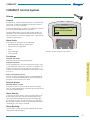
COMPACT
COMPACT Control System
Hand-held Micro Terminal/Control Panel
Heating, COMPACT Air & Heat
Settings................................................................................. 64
Language.............................................................................. 64
Flow unit............................................................................... 64
Min./max. Setting.................................................................. 64
Initial Setting......................................................................... 64
Electric Air Heater.................................................................. 71
Manually Set Heating ............................................................ 71
Automatic Heating................................................................ 71
Controls
Electric Air Heater.................................................................. 72
Air Heater for Hot Water....................................................... 72
Heating BOOST...................................................................... 72
Intermittent Night-time Heating............................................. 72
Morning BOOST.................................................................... 72
Preheating the Air.................................................................. 72
Controls ................................................................................ 64
Time switch clock (timer)....................................................... 64
Starting Sequence.................................................................. 64
Temperature Regulation
ERS Regulation...................................................................... 65
Summer Night Cooling.......................................................... 66
Set Point Displacement.......................................................... 66
External Temperature Sensors................................................ 66
Supply Air Regulation............................................................ 67
Extract Air Regulation............................................................ 67
Outdoor Compensation......................................................... 67
Flow/Pressure
Cooling
Control Possibilities ............................................................... 73
Functions............................................................................... 73
Operational Functions Set from an Ext. Device
Damper Control..................................................................... 74
Outputs................................................................................. 74
Inputs.................................................................................... 74
IQnomic Plus.......................................................................... 74
Alarms
General................................................................................. 75
Alarm Limits.......................................................................... 75
Fire Alarms............................................................................ 75
External Alarms..................................................................... 75
Alarm Priority........................................................................ 75
Alarm Blocking...................................................................... 75
Communication
Filters
General................................................................................. 70
Filter Monitoring.................................................................... 70
General................................................................................. 76
Web Communication via Network ........................................ 76
Logging................................................................................. 76
Service Functions
Rotary Heat Exchanger
Controls................................................................................. 70
Defrosting............................................................................. 70
Cooling Energy Recovery....................................................... 70
Air Purging Operation............................................................ 70
Rotation Monitor................................................................... 70
Prolonged Heat Exchanger Operation.................................... 70
Temperature Efficiency Calculation........................................ 70
Airflow Adjustments.............................................................. 77
Readings................................................................................ 77
Manual Test........................................................................... 77
Registered design. The company reserves the right to make design changes without prior notice.
20090901www.swegon.com
63
COMPACT Control System
Fan Regulation....................................................................... 68
Flow Regulation..................................................................... 68
Demand Control.................................................................... 68
Slave Control......................................................................... 68
Airing.................................................................................... 68
Pressure regulation................................................................ 68
Seasonally Compensated Airflow........................................... 68
Flow/pressure Regulation to min. set point............................ 68
Density-corrected Airflow...................................................... 68
Zero Calibration..................................................................... 68
Clean Air Contriol.................................................................. 69
Heating, COMPACT Unit & Top
COMPACT
COMPACT Control System
Hand-held Micro Terminal/Control Panel
Settings
Language
The language desired can be set here. Normally this setting is entered when the air handling unit is started for
the first time and the question CHANGE? automatically
appears on the control panel screen.
However, the language setting can be changed at any
time.
Flow unit
The flow unit desired can be set here. l/s, m3 /s, m3 /h.
Min./max. setting
Used for limiting the setting range at user level for setpoints and min. and max. limits of temperature.
Initial setting
The two base settings can be saved and used for setting
the air handling unit for summer conditions and winter
conditions, for instance.
The settings can also be reset to the initial factory settings. However, the preset values for communication and
alarm priority are not reset if the factory settings are reinstated.
Controls
Controls
Starting sequence
The unit normally operates in the automatic operation
mode and is then controlled via the internal time switch
clock (timer).
The COMPACT system has a starting sequence with factory-preset time delay between each step as follows:
It is also possible to control the air handling unit manually.
In addition, the air handling unit can be externally controlled via communication or via external accessories such as
presence detectors.
The control unit has as standard two outputs and two
inputs for external operation functions (with the TBIQ IQnomic Plus module the number of inputs and outputs respectively can be increased to four). The outputs can be
used for indicating in-operation status and the inputs can
be used for unit operation regulated via presence detectors, for instance.
Time switch clock (timer)
The current date and time can be set and preset and adjusted whenever required. The Time switch clock (timer)
automatically takes leap years into consideration.
The system automatically manages changes between
summer/winter time to EU Standard. The function can,
however, not be blocked.
Times and days can be set when the unit is to run in the
high speed mode, low speed mode or be switched off.
Eight different time channels (scheduling) can be set. If
the same in-operation periods are to apply every day of
the week (Monday-Sunday), it will be sufficient to program one time channel.
The year channels make it possible to set deviating inoperation times for certain periods in the year, such as
longer holidays. Eight different year channels (yearly time
schedules) can be set.
64
1.The damper relay is energised and opens the shut-off
damper (if installed).
2.Time delay: 30 seconds.
The extract air fan starts and rotary heat exchanger is
controlled to the max. energy recovery setting. The air
heater for hot water (if installed) is activated to generate 40% of its max capacity.
3. Time delay: 90 seconds.
The supply air fan starts up.
4.Time delay: 90 seconds.
The temperature regulation (control) function begins
according to its regular settings.
The starting sequence prevents the extract air fan from
starting up if the shut-off damper is closed. By starting
the extract air fan first, and controlling the heat exchanger to the max. recovery setting, the system also avoids
chilling the premises with cool supply air under cold
weather conditions.
COMPACT
COMPACT Control System
Temperature regulation
ERS Regulation 1
The control unit regulates the ratio between the supply air
and extract air temperature according to a factory-preset
curve.
1) Breakpoint in °C
(based on the extract air temperature).
2) The temperature differential above the breakpoint is
selected in steps.
3) The temperature differential below the breakpoint is
selected in °C.
See the diagram: ERS Regulation 1, to the right for COMPACT Air & Heat and COMPACT Unit & Top respectively.
22
ep
St
Ste
p2
Step
1
ti a
l
20
3
Breakpoint
di
ff
er
en
18
SA
/E
A
16
12
14
16
18
20
22
24
26
Extract air temperature °C
Factory setting: Step 1. Breakpoint: 20°C. SA/EA differential: 2°C.
Involves the following: If the extract air temperature is below 20°C
(breakpoint), the supply air temperature setpoint will be automatically
regulated to be 2°C (EA/SA differential) lower.
If the extract air temperature is above 20°C, the supply air temperature
setpoint will follow the curve according to Step 1.
ERS Regulation 1, COMPACT Unit & Top
22
p
Ste
20
Step 2
Breakpoint
18
Step 3
ff
er
en
ti a
l
16
1
SA
/E
A
di
14
12
Step 4
10
12
14
16
18
20
21
22
24
26
Extract air temperature °C
Factory setting: Step 1. Breakpoint: 20°C. SA/EA differential: 2°C.
Involves the following: If the extract air temperature is below 20°C
(breakpoint), the supply air temperature setpoint will be automatically
regulated to be 2°C (EA/SA differential) lower.
If the extract air temperature is above 20°C, the supply air temperature
setpoint will follow the curve according to Step 1.
65
COMPACT Control System
Control Sequence
The temperature efficiency of the air handling unit’s heat
exchanger is modulated to provide max. heat recovery.
After that, the air heater for reheating, if installed, will
begin to generate heat.
If an air heater for reheating the supply air is not installed,
or if the heating power in the air heater for reheating is
not sufficient, the supply air fan or both the supply air
and the exhaust air fans will automatically and variably
be decelerated to discharge supply air at the min. airflow
setpoint.
A neutral zone can be preset, which allows a lower supply
air temperature setpoint before the downspeed fan control (fan deceleration) function begins.
When the supply airflow is regulated to a lower rate, the
heat exchanger will have ”excess heat”, i.e. warm extract
air, giving it capacity to attain and maintain the supply air
temperature required. As the supply airflow is controlled
to a lower rate, the air pressure in the premises becomes
sub-atmospheric and this instead causes outdoor air to be
sucked in through untight spots (leakage points) such as
doors and windows. The ordinary heating system of the
premises must be sized for heating this outdoor air.
Supply air temp. setpoint °C
ERS Regulation refers to Extract air temperature-Related
Supply air temperature control. This means that the temperature of the supply air is regulated in relation to the
temperature of the extract air.
Under normal circumstances, the supply air temperature is
regulated to be a few degrees lower than the extract air
temperature. In this way, the heat exchanger will provide
optimal performance, and this means excellent operating economy. ERS control is suitable for use when there
is excess heat in the premises generated, for example,
by machinery, lighting or people and the premises have
supply air devices suitable for discharging air below room
temperature.
ERS Regulation is standard in the COMPACT Air and
COMPACT Heat systems.
ERS Regulation 1, COMPACT Air & Heat
Supply air temp. set point °C
ERS Regulation (control)
COMPACT
COMPACT Control System
Temperature regulation
ERS Regulation 2
Used if the factory preset performance curve in the ERS
Control 1 function does not provide the results desired to
meet special needs and conditions. Depending on what
settings are entered, the installation of air heaters for
reheating may be required.
An individually adjusted curve regulates the supply air/
extract air temperature ratio.
See the ERS Regulation Diagram to the right.
ERS Regulation 2
22
Y = Supply air temperature setpoint °C
ERS Regulation, continued
20
2
15
The lower temperature at night is utilized to cool down
the building structure.
If the function is activated, the air handling unit will, if
required, operate in the high speed mode without energy
recovery and without activating the air heater, if included
in the system.
This will cause the cooling load to decrease during the
first hours of the day. If a cooling unit is installed, it will
not need to be operated, thus offering savings. If no cooling unit is installed, a certain cooling effect will still be
achieved.
Set point displacement
Set point displacement is used for changing the set point
for supply air and extract air temperatures. The temperature can be increased or decreased at certain times of the
day by means of an external timer or potentiometer, for
instance.
The set point can be influenced by ±5 °C by means of 0 10 V external control.
External temperature sensors
There is provision for connecting external temperature
sensors, which can be used when the air handling unit’s
internal sensor does not provide representative values.
The External Extract air/Room function measures the
extract air temperature in a larger room or in the duct
system, instead of the temperature inside the air handling
unit. A temperature sensor for location in a room, is included as standard for the COMPACT Heat system.
The External Outdoor function measures the air temperature outdoors, instead of the temperature inside the air
handling unit.
66
3
10
9
Summer night cooling
1
12
15
20
X = Extract air temperature °C
25
27
Factory settings – breakpoints:
X1 X2 = 20 °C. X3 = 22 °C.
Y1 = 20 °C. Y2 = 18 °C. Y3 = 14 °C.
Involves the following: If the extract air temperature is below 15 °C (X1)
the supply air temperature setpoint will constantly be 20 °C (Y1).
If the extract air temperature is 20 °C (X2) the supply air temperature
setpoint will be 18 °C (Y2).
If the extract air temperature is above 22 °C (X3), the supply air temperature setpoint will constantly be 14 °C (Y3).
COMPACT
COMPACT Control System
Temperature regulation
Applies to COMPACT Unit & Top only
Applies to COMPACT Unit & Top only
Supply Air Regulation (control)
Outdoor Compensation
Supply air regulation involves keeping a constant supply air temperature without consideration to the load in the premises.
Temperature
Control Sequence
The temperature efficiency of the air handling unit’s heat exchanger is modulated to provide max. heat recovery.
After that, the air heater for reheating, if installed, will begin to
supply heat.
If an air heater for reheating the supply air is not installed, or
if the heating power in the air heater for reheating is not sufficient either, the supply air fan or both the supply air and the
exhaust air fans will automatically and variably be decelerated to
discharge supply air at the min. airflow setpoint.
A neutral zone can be preset, which allows a lower supply air
temperature setpoint before the downspeed fan control function begins.
As the supply airflow is controlled to a lower rate, the air pressure in the premise becomes sub-atmospheric and this instead
causes outdoor air to be sucked in through untight spots (leakage points) such as doors and windows. The ordinary heating
system of the premises must be sized for heating this outdoor
air.
Extract Air Regulation
Extract air control involves keeping a constant temperature in
the extract air duct (the premises), by regulating the supply air
temperature.
If the function is selected, the temperature setpoint is displaced
relative to the outdoor temperature according to a summer
curve or a winter curve. It is possible to set the slope of the
curves and their starting and end points. In conjunction with
supply air or extract air control only.
See the Outdoor Compensation Diagram below.
Negative summer compensation is also possible to preset.
Outdoor compensation
Y1
X1
X4
X2
COMPACT Control System
When the supply airflow is regulated to a lower rate, the heat
exchanger will have ”excess heat”, i.e. warm extract air, giving
it capacity to attain and maintain the supply air temperature
required.
Outdoor compensation can be activated if the premises are affected to an unusually high degree by cold and heat, via large
windows, for instance.
Y = Temperature displacement °C
Supply air regulation can be used when the load and temperatures of the premises are predictable. In most cases this requires
the installation of an air heater for reheating, possibly an air
cooler as well.
Y2
X3
The lowest and the highest permissible supply air temperatures
are specified while the COMPACT keeps the extract air temperature constant.
The result will be a uniform temperature in the premises regardless of the load. Extract air regulation requires the installation of an air heater for reheating, possibly an air cooler as well.
The extract air temperature is measured by the temperature
sensor inside the COMPACT unit. If this internal temperature
sensor does not give adequate representative extract air temperature readings, an external room temperature sensor can be
installed and can be wired to terminals on the control unit.
Control Sequence
The temperature efficiency of the air handling unit’s heat exchanger is modulated to provide max. heat recovery.
After that, the air heater for reheating, if installed, will begin to
generate heat.
X = Outdoor air temperature °C
Winter compensation according to the factory settings involves the following:
Outdoor temperature of +10 °C (Breakpoint X2): Compensation starts
and gradually proceeds between 0-3 °C down to an outdoor air temperature of -20 °C.
Outdoor air temperature -20 °C (Breakpoint X1): Constant compensation takes place with 3 °C (temperature displacement Y1).
Summer compensation in accordance with factory settings involves the
following:
Outdoor temperature +25 °C (Breakpoint X3): Compensation starts
and gradually proceeds between 0–2 °C up to an outdoor temperature
of +40 °C.
Outdoor temperature +40 °C (Breakpoint X4): Constant compensation
takes place with 2 °C (temperature displacement Y2).
67
COMPACT
COMPACT Control System
Flow/Pressure
The type of control can be selected individually for the
supply air fan or the extract air fan.
Flow Regulation (control)
Flow control involves operating the air handling unit to
keep the preset airflow constant. The speed of the fans
is automatically regulated to provide correct airflow even
if the filters begin to become clogged; if air diffusers or
grilles become blocked, etc.
Constant airflow is advantageous, since the airflow is
always exactly as it has been preset from the beginning.
Demand Control
Demand control involves regulating the flow requirement
via external sensors, such as a carbon dioxide sensor that
is wired to the control unit. The setpoint, separate for low
speed mode and high speed mode, is preset as a percentage of the input signal.
Applies to COMPACT Unit & Top only
Slave Control
Slave control involves constantly regulating the flow to be
the same from the one fan as from the other fan. If one
fan is pressure-controlled or demand-controlled, the other
one can be controlled as a slave to generate the same airflow.
Applies to COMPACT Air & Heat only
Airing
Can be manually activated during a break if there are
many occupants in the room. The air handling unit fans
will then operate at max. speed during the preset period
(Factory Setting: 15 minutes).
Applies to COMPACT Unit & Top only
Pressure Regulation
Pressure control involves automatically varying the airflow
to provide constant pressure in the ducting. This type of
control is therefore also called VAV Regulation (Variable
Air Volume).
Pressure regulation is used, for example, when damper
functions regulate the airflow volume in sections of the
ventilation system.
The duct pressure is measured by an external pressure
sensor in the ductwork. The setpoint required (separate
for low speed and high speed) is adjusted in Pa.
68
Seasonally Compensated Airflow
Outdoor compensation of the airflow can be activated if
it is desired to reduce the airflow in the wintertime.
Seasonally compensated airflow is an energy-saving function that reduces the costs for operating the fans, reheater and the ordinary heating system of the building.
This function cannot be combined with flow regulation or
pressure regulation. The function has no effect if the airflow is demand-controlled.
Y = Reduction of the airflow %
Fan Regulation (control)
0%
X2
-10%
-20%
-30%
Y1
-40%
X1
-50%
-30
-20
-10
0
+10
+20
X = Outdoor air temperature °C
Outdoorcompensation according to the factory settings involves the
following:
Outdoor temperature of +10 °C (Breakpoint X2): Compensation
starts and gradually proceeds between 0-30 % down to an outdoor
air temperature of -20 °C.
Outdoor air temperature -20 °C (Breakpoint X1): Constant compensation takes place with 30 % (max. reduction Y1).
Flow/pressure Regulation to Min. Setpoint
If the heating load increases while the unit is operating
in the ERS regulation or supply air control mode, then
downspeed fan control for reducing the supply airflow
or both the supply air and extract airflow to the min. set
point will be the last step in the control sequence.
An adjustable reduction in temperature allows a lower
supply air temperature setpoint, before downspeed control is initiated.
Density-corrected Airflow
The density of the air is different at different temperatures. This means that a specific volume of air changes at
various air densities.
The COMPACT automatically corrects this, so that correct
air volume is always obtained.
Zero Calibration
The zero value of the pressure sensor is checked and if
the value is not correct, a new calibration is carried out.
Switches in automatically every time the fans are stopped
for more than three minutes.
COMPACT
COMPACT Control System
Flow/Pressure
Clean Air Control
The Clean Air Control function is used in ventilation systems where the aim is to regulate the airflow according to
the content of emission/impurities in the room air.
The VOC sensor measures the content of emissions/impurities in % VOC.
When an occupant emits CO2, this creates a proportional
amount of emissions/impurities which are measurable by
the VOC sensor. For an approximate translation of the %
VOC to CO2 content, see the diagram.
When the VOC sensor measures contents of emissions/
impurities that are lower than the preset value; the air
handling unit’s supply air and extract air flows are then
equivalent to the preset min. flows. When the VOC sensor instead measures contents of emissions/impurities that
are higher than the preset limit value, the supply air and
extract air flows are variably increased until the preset
value or max. flow is reached.
CO2 content, ppm
One VOC sensor (Volatile Organic Compound) is mounted
as standard inside COMPACT Air & Heat units. For COMPACT Unit & Top units, the VOC sensor (TBLZ-1-60) is an
accessory and must be ordered separately.
2000
1500
1000
400
10
20
30
40
50
60
70
80
90
% VOC
Example:
800 ppm is equivalent to approx. 30% VOC.
69
COMPACT Control System
If influenced by other emissions/impurities in the air, such
as cooking odours, cigarette smoke, etc., the VOC content increases in relation to the CO2 content.
COMPACT
COMPACT Control System
Filters
General
Filter Monitoring
As the filters become fouled, the pressure drop across
them increases and the speed of the fans automatically
increases to compensate the resistance caused by the
clogged filter medium.
Estimated Filter Monitoring
Standard function in which the current values are continuously compared with values determined by calibration for
new filters and the degree of fouling is estimated.
The control system continuously compares the current
filter status with values determined by calibration that was
carried out in conjunction with commissioning and filter
change. An alarm is initiated when the preset alarm limit
for each filter is exceeded.
Filter Monitoring by Means of Pressure Sensors.
If variations in pressure arise in the ventilation duct
system, for example when VAV regulation is used, the
filter monitoring function can be supplemented with
TBLZ-1-23 pressure sensors. The filter pressure sensors
then continuously measure the current pressure drop
across the filters and in this way ensure correct filter monitoring in this type of ventilation system as well.
The current filter status reading can be viewed at any
time.
Rotary heat exchanger
Controls
Air Purging Operation
The rotary heat exchanger starts up on a heating load. On
an increasing heating load, the control system regulates
the rotation speed of the heat exchanger rotor and thus
the degree of heat recovery efficiency.
The air purging function prevents clogging in the air passages inside the heat exchanger rotor. Purging operation is activated when the unit is operating but there is
no heating load and the heat exchanger rotor is idle. The
heat exchanger rotor then rotates for 10 seconds every 10
minutes to purge its surfaces clean of impurities.
Defrosting
In environments where the extract air can occasionally be
humid, the defrosting function can be activated to protect
the heat exchanger from frosting. The function continuously monitors the condition of the heat exchanger rotor
to prevent it from becoming clogged due to condensate
that has frozen inside the rotor passages.
The function requires the connection of a separate pressure sensor (accessory).
When the function is activated the pressure drop across
the heat exchanger is continuously measured. If the pressure drop exceeds the preset limit value, a defrosting sequence is carried out. This involves, decreasing the rotor
speed to allow warm extract air to melt any possible frost.
Cooling Energy Recovery
The heat exchanger rotates at max. speed and in this way
recovers the relative cooling energy available inside the
premises. Switches in when there is a cooling load and
when the outdoor air temperature is higher than the extract air temperature.
70
Rotation Monitor
The rotation monitor sensor continuously monitors the
heat exchanger. If a malfunction forces the heat exchanger to stop, an alarm is initiated and the air handling unit is
stopped if the outdoor temperature is low.
Prolonged Heat Exchanger Operation
After the unit has been ordered to stop, the fans continue to operate for a certain period before they come to a
stop.
To prevent the supply air from chilling down the premises
when the unit is shut down, the rotary heat exchanger
automatically continues to rotate for about one minute.
Temperature Efficiency Calculation
The temperature efficiency is calculated and displayed (0
– 100%).
COMPACT
COMPACT Control System
Heating
Applies to COMPACT Air & Heat only
Applies to COMPACT Heat only
Electric Air Heater
Manually Set Heating
The function is automatically activated when the TBLE
air heater is connected (standard in the COMPACT Heat
system).
Heating
Can be manually activated for increasing the temperature
in the room to be put to use. The controller controls the
unit’s air heater and airflow to meet the load (factory setting: 45 minutes).
On a heating load, the power supplied to the air heater is
controlled in sequence with the heat exchanger.
Whenever the air velocity through the unit is low, the
power supplied is automatically reduced to prevent the
electric heating elements from becoming overheated.
After the air heater has been in operation, the supply air
fan is always run for 3 minutes more for cooling the air
heater afterward. This occurs also if the air handling uit
has been manually switched off or automatic functions
have switched it off.
The function should be used only if the room is vacant
since the airflows and noise levels differ from the normal
ones.
Heating + Recirculation
Can be manually activated if very quick heating is desired in the room to be put to use. The air handling unit’s
controller controls the air heater and airflow to meet the
load, the supply of outdoor air is shut off and room air is
circulated (factory setting: 45 minutes).
The function should be used only if the room is vacant
since the airflows and noise levels differ from the normal
ones.
Automatic Heating
Intermittent Night-time Heating
The air handling unit is started and stopped within the
preset temperature limits for heating the room when it is
normally stopped by the time switch clock (timer).
The function is otherwise according to
Heating+Recirculation above.
Morning BOOST
The air handlng unit starts at the preset time, before the
start time of the time switch clock, with preset temperature setpoint for heating the room.
The function is otherwise according to
Heating+Recirculation above.
71
COMPACT Control System
The functions can be selected at Installation Level.
COMPACT
COMPACT Control System
Heating
Applies to COMPACT Unit & Top only
Applies to COMPACT Unit & Top only
Electric Air Heater
Preheating the Outdoor Air
The function is automatically activated when the TBLE air heater
is connected.
Preheating the outdoor air if the outdoor temperature is cold
and the humidity is high can prevent condensation from forming in the air handling unit’s filters. Preheating may also be necessary to heat the air if during a spell of extremely cold weather.
On a heating load, the power supplied to the air heater is controlled in sequence with the heat exchanger.
Whenever the air velocity through the unit is low, the power
supplied is automatically reduced to prevent the electric heating
elements from becoming overheated. After the air heater has
been in operation, the supply air fan is always run for 3 minutes
more for cooling the air heater afterward. This occurs also if the
air handling uit has been manually switched off or automatic
functions have switched it off.
Air Heater for Hot Water
The function is automatically activated when the TBLE air heater
is connected.
The outdoor air preheating function requires placing the air
heater in the outdoor air duct and the TBLZ-1-53-a (controlling
the air heater preheating function).
The TBVL valve set can be used for the air heater for hot water
and if a pump is required, the TBPA pump set can be used.
The following types of air heater can be selected:
• Electric air heater of pause/pulse type
• Electric air heater, 0–10 V.
• Air heater for hot water with anti-frost monitor function.
On a heating load, the valve and actuator are controlled in sequence with the heat exchanger.
• Air heater for hot water without anti-frost monitor function.
Pump Control
Control Function
The circulation pump starts when there is a heating load and if
the outdoor temperature is low. Other times, the pump is exercised at regular intervals.
Temperature sensors in the ducts keep the preset temperature
constant. The setpoint required can be set in the hand-held
micro terminal.
Anti-frost Monitor
Anti-frost Monitor Function
The air handling unit is stopped if freezing inside the air heater
is likely. The anti-frost function keeps the air heater warm at
13°C while the air handling unit is in operation and 25°C when
the unit is switched off.
The alarm limit and heat keeping function settings are common
for the preheating coil and the ordinary air heater in the supply
air path.
Heating BOOST
Provision is available for controlling pump operation. The settings for exercising will then be common with the ordinary air
heater in the supply air ductwork.
From normal flow regulation, both the supply air and the extract airflows are increased to carry more heat into the
premises.
The fans are allowed to operate in the range between current
flow modes (low speed, high speed) and the preset max speed
flow.
The function only works if the air handling unit is operating in
the extract air regulation mode.
Intermittent Night-time Heating
The air handling unit is started and stopped within the preset
temperature limits for heating the premises when it is normally
stopped by the time switch clock (timer).
Intermittent night-time heating requires an external room
sensor, and that the air handling unit is connected to an air
heater for reheating.
When the function is activated, the air handling unit detects
when the room temperature drops below the preset start temperature. The unit starts with preset flows and the supply air
temperature setpoint.
Morning BOOST
The air handling unit starts at the preset time, before the start
time of the time switch clock, with preset temperature setpoint
for heating the room.
72
Pump Control
Electric Air Heater
Overheat monitor and recooling whenever the air handling unit
stops.
COMPACT
COMPACT Control System
Cooling
Control Possibilities
The IQnomic Plus, an extra module for the air handling
unit’s control system is required for controlling waterbased cooling.
The regular outputs of the air handling unit are used for
controlling cooling with direct expansion. If none of these
are sufficient for cooling, the IQnomic Plus can be used.
Control Reaction Speed
The control reaction speed denotes the time delay between various cooling steps to enable the provision of
cooling capacity from a compressor, for instance, before
switchover to the next step occurs.
The following control possibilities are available for controlling other types of cooling equipement:
Cooling BOOST
Cooling BOOST involves increasing the supply air and extract air airflows to convey more cooling energy to the
premises.
• DX-cooling, 1 step
Connection to independent contacts for starting/stopping the cooling unit.
The flow increase takes place between current flow and
preset max. flow. Start limits in relation to the setpoint for
minimum supply air temperature can be preset.
• DX-cooling, 2 steps
Connection to two independent contacts for controlling cooling in two steps.
This function cannot be combined with pressure regulation.
• DX-cooling, 3 steps, binary mode
Connection to two independent contacts for controlling cooling in three steps.
• Comfort
Cooling BOOST Comfort involves first starting the cooling equipment when cooling is required and then increasing the airflow.
• Stepless control, 0-10 V DC
Connection to a 0-10 V DC control signal for variable
control of a cooling coil/cooling unit. A 24 V DC power
supply for the damper actuator is also ready-to-use in
the COMPACT.
The function can be selected in five variants as follows:
• Economy
Cooling BOOST Economy involves first increasing the
airflow when cooling is required and then starting the
cooling equipment.
The function can also operate without the cooling
function activated.
Functions
The function requires that the outdoor air temperature
is at least 2 °C lower than the extract air temperature
in order to be activated. Normal cooling operation is
activated if the temperature difference is too small.
Cooling, Min. Airflow
If the unit's airflow is lower that this limit, the cooling
function will be blocked.
Restarting Period
The restarting period is the period from when the cooling unit has stopped until when it can start up again. The
time delay prevents the cooling unit from starting and
stopping continuously.
Neutral Zone
The neutral zone between the setpoint for cooling and
the setpoint for heating can be preset for preventing the
cooling and heating systems from operating too closely to
one other.
Outdoor Temperature Limited Start
If DX cooling is used, it is possible to set the outdoor temperature limit at which the cooling unit is allowed to start.
Each step has a separate minimum permissible outdoor
temperature setting for starting the cooling unit.
• Sequence
The cooling BOOST Sequence is used if a cooling unit is
sized for a higher cooling flow than normal flow.
If there is a cooling load, the flow is increased up to the
preset max. flow before the cooling function is activated. The cooling function is delayed 1 minute after the
airflow is increased.
• Comfort + Economy
The comfort variant and the economy variant can be
combined.
• Economy + Sequence
The economy variant and the sequence variant can be
combined.
Pump Control
If an air cooler for chilled water is used, there is provision
for controlling the pump. Other times, the pump is exercised at regular intervals.
73
COMPACT Control System
• Stepless control, 10-0 V DC
Same as item 4, but the control signal is inverted.
COMPACT
COMPACT Control System
Operational Functions Set from an External Device
Damper Control
Inputs
Dampers open on starting the air handling unit and close
on shutting down the air handling unit. The controls and
24 V power supply wiring can be connected via terminals
on the air handling unit.
The control unit has two digital inputs that can be used
for external operation functions. These functions can be
selected in the control panel/hand-held terminal.
Outputs
The control unit has two relay-controlled outputs that can
be used for external operation functions. These functions
can be selected in the control panel/hand-held terminal.
A maximum of two of the functions stated below can
be combined as standard; using the TBIQ IQnomic Plus
module, the number of combinations can be increased to
four:
• Damper: For control of the outdoor air/exhaust air
damper.
• Operation: Indicates that the unit is operating.
• Low speed: For indicating low speed operation.
• High speed: For indicating high speed operation.
• A Alarm: For type A group alarm.
• B Alarm: For type B group alarm.
• Heating: For controlling external heating/circulation
pump.
• Cooling: For controlling external cooling, cooling
output 1.
• Cooling: For controlling external cooling, cooling
output 2.
74
A maximum of two of the functions stated below can
be combined as standard; using the TBIQ IQnomic Plus
module, the number of combinations can be increased to
four:
• External stop: For stopping the air handling unit from
an external source.
• External low speed: For external overtime operation
from stop to low speed operation.
• External high speed: For external overtime operation
from stop or low speed operation to high speed operation.
• External alarm 1: For connection of external alarm 1.
• External alarm 2: For connection of external alarm 2.
• External reset: For connection of the pushbutton for resetting a tripped alarm.
• External fire alarm: For tripping the fire alarm from an
external fire protection device.
IQnomic Plus
IQnomic Plus is an additional module for extra control
functions, such as external monitoring and cooling.
COMPACT
COMPACT Control System
Alarms
General
Temperatures, airflows and components are continuously
supervised. If abnormal conditions or possible malfunctions arise, an alarm is initiated.
Alarms are indicated by an alarm text and flashing LED on
the control panel/hand-held micro terminal.
***
Complete description of alarms and setting options are
specified in the Operating and Maintenance Instructions
for the COMPACT (see www.swegon.com). A general description is given below:
RES?
ALARM No. 52
***
SUPPLY AIR FILTER FOULED
Alarm Limits
Alarm limits can be preset for the following:
•
•
•
•
•
Nonconforming supply air temperature.
Min. extract air temperature.
Filters.
Heat exchanger.
Service period.
Examples of Menu Images for Filter Alarms.
Fire Alarms
External fire alarm
Used for external fire-control equipment.
COMPACT Control System
Internal fire alarm
The air handling unit’s internal temperature sensors serve
as fire protection thermostats. An alarm is initiated if the
supply air temperature sensor registers more than 70 °C
or when the extract air temperature sensor registers more
than 50 °C.
Fans, in the event of a fire
The fans in the air handling unit can be controlled to operate in the desired speed mode for evacuating combustion gases in the event of a fire alarm.
External Alarms
External alarms 1 and 2
The external alarms can be used for external functions
such as motor protection for circulation pump and service
alarm for smoke detectors.
Alarm Priority
In the case of all the alarms, you can assign priority A or
B and chose whether or not the red alarm LED on the
control panel/hand-held micro terminal shall light up in
the event of an alarm. For certain alarms it is also possible to choose whether or not the air handling unit will be
switched off if this alarm is initiated.
Alarm Blocking
Certain alarms can be activated or blocked, for example
temperature and flow alarms.
75
COMPACT
COMPACT Control System
Communication
General
Provision for communication and supervision is integrated
as standard into the COMPACT system.
The unit is ready to be connected via TCP/IP, and EIA-485
for supervision via existing system.
The following protocols can currently be obtained as
standard without an extra communication unit: Modbus
TCP, Modbus RTU, Metasys N2 open, BACnet and Exoline.
Communication can also be established via LON and
Trend using the communication unit (accessory).
The scope available for communication is conditional on
the software and programming of the same. The COMPACT air handling unit in itself offers possibility for overall
communication of readings, settings and functions.
Further information about interfaces, protocols and configuration is available at www.swegon.com.
Web Communication via Network
Communication can take place via TCP/IP using an ordinary internal network. All that is needed is an ordinary
computer with web browser, such as Internet Explorer.
Connection to the network can be done just as easily as
connecting a printer, for instance.
Comprehensive communication of values, settings and
function is available. In addition, there is also a mail function for forwarding alarms.
Logging
Logged values for the parameters desired can be selected
if web communication is used. The values are presented in
the form of a curve diagram that allows the user to review
prior changes made back in time.
Logging can also be carried out by connecting an MMC
card to the air handling unit’s control unit. The log files
can then be opened in the Microsoft Excel program, by
means of a standard MMC card reader.
Microsoft Excel can manage max. 65,000 log entries. If
you set 1-minute logging intervals, logging will then occur
during 45 days. If you set 5-minute logging intervals,
(actory setting)logging will occur during 225 days. 65,000
logging entries fill approx. 40 Megabytes on an MMC circuit card.
76
Typical flow diagram for web communication.
COMPACT
COMPACT Control System
Service Functions
Airflow Adjustments
The speed of the fans can be locked for up to 72 hours
for adjusting the airflows through the duct system and
the air diffusers.
Readings
Using a special Readings menu, it is possible to read current operation readings such as flows, temperatures, control sequence output values, status on the inputs and outputs, filter pressure, SFP values, alarm history, etc.
Manual Test
Via a special test menu, the inputs and outputs, fans and
heat exchanger, etc. can be manually tested.
Used for installation or troubleshooting to test that wired
connections and functions operate correctly.
COMPACT Control System
77