1
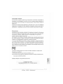
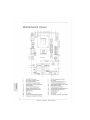
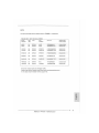
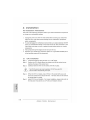
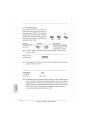
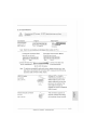
P4i45D+
Quick I n s t a l l a t i o n Guide
English
iii)'
'l' X
Deutsch
Franęais
Itatiano
Espanot
Русский
Copyright Notice:
No part of this installation guide may be reproduced, transcribed, transmitted, or
translated in any language, in any form or by any means, except duplication of
documentation by the purchaser for backup purpose, without written consent of
AS Rock Inc.
Products and corporate names appearing in this guide may or may not be registered
trademarks or copyrights of their respective companies, and are used only for
identification or explanation and to the owners' benefit, without intent to infringe.
Disclaimer:
Specifications and information contained in this guide are furnished for informational
use only and subject to change without notice, and should not be constructed as a
commitment by ASRock. ASRock assumes no responsibility for any errors or
omissions that may appear in this guide.
With respect to the contents of this guide, ASRock does not provide warranty of any
kind, either expressed or implied, including but not limited to the implied warranties or
conditions of merchantability or fitness for a particular purpose.
In no event shall ASRock, its directors, officers, employees, or agents be liable for
any indirect, special, incidental, or consequential damages (including damages for
loss of profits, loss of business, loss of data, interruption of business and the like),
even if ASRock has been advised of the possibility of such damages arising from any
defect or error in the guide or product.
№
This device complies with Part 15 of the FCC Rules. Operation is subject to the
following two conditions:
(1) this device may not cause harmful interference, and
(2) this device must accept any interference received, including interference that
may cause undesired operation.
ASRock Website: http://www.asrock.com
Published March 2004
Copyright©2004ASRock INC. All rights reserved.
ASRock P4i45D+
Motherboard
1
Motherboard
Layout
17
16
1
PS2_USB_PWR1 jumper
2
CPU fan connector (CPUJ=AN1)
3
CPU heatsink retention module
4
CPU socket
5
7
g
North Bridge controller
6
184-pin DDR DIMM slots (DDR 1 - 2 )
ATX power connector (ATXPWR1)
8
Primary IDE connector (1DE1, Blue)
Secondary IDE connector (IDE2, Black)
10
Clear CMOS (CLRCMOSO, 2-pin jumper)
11
AGP slot (AGP1)
12
South Bridge controller
13
USB 2.0 header (USB45, Blue)
14
Floppy connector (FLOPPY1)
15
System panel connector (PANEL1)
16
External speaker connector (SPEAKER 1)
17
Chassis fan connector (CHA_FAN1)
18
Infrared module connector (IR1)
19
BIOS FWH chip
20
PCI slots ( P C M - 4 )
21
PCI LAN
22
AUDIO CODEC
23
JL1 jumper
24
JR1 jumper
25
Front panel audio connector (AUDI01)
26
Internal audio connector: AUX1 (White)
27
Internal audio connector: CD1 (Black)
ASRock P4i45D+
Motherboard
11
I
Parallel port
2
RJ-45 port
3
Game port
4
Microphone (Pink)
5
Line In (Light Blue)
6
Line Out (Lime)
7
USB 1.1 ports (USB 2,3)
9
Serial port (C0M1)
8
USB 2.0 ports (USB 0,1)
10
PS/2 keyboard port (Purple)
II
PS/2 mouse port (Green)
ASRock P4i45D+
Motherboard
- 3
II
1. Introduction
Thank you for purchasing ASRock P4i45D+ motherboard, a reliable motherboard
produced under ASRock's consistently stringent quality control. It delivers excellent
performance with robust design conforming to ASRock's commitment to quality and
endurance.
This Quick Installation Guide contains introduction of the motherboard and step-bystep installation guide for new DIY system builders. More detailed information of the
motherboard can be found in the user manual presented in the product CD-ROM.
Because the motherboard specifications and the BIOS software might be
updated, the content of this manual will be subject to change without
notice. In case any modifications of this manual occur, the updated
version will be available on ASRock website without further notice.
You m a y find the latest memory and CPU support lists on A S R o c k
website as well.
A S R o c k website
http://www.asrock.com
Specifications
Platform:
CPU:
ATX form factor (12.0" x 7.0", 30.5 x 17.8 cm)
Socket 478 for Intel® Pentium®4/ Celeron® (Prescott, Northwood,
Willimate) processor
Chipsets:
North Bridge:
Intel" 845D chipsets, standard FSB 400MHz,
supports FSB 533MHz / 800MHz at over-clocking mode
(see CAUTION 1),
with Hyper-Threading Technology ready (see CAUTION 2);
South Bridge:
Intel® ICH2
Memory:
2 DDR DIMM Slots: DDR1 and DDR2
supports PC2100(DDR266), Max. 2GB
PC3200(DDR400) at overclocking mode, Max.1GB
(see CAUTION 1)
IDE:
IDE1: ATA 100 / Ultra DMA Mode 5;
IDE2: ATA 100 / Ultra DMA Mode 5;
Can connect up to 4 IDE devices
Floppy Port:
Supports 1 floppy disk drive
Audio:
5.1 channels AC'97 Audio
PCI LAN:
Speed: 802.3u (10/100 Ethernet), supports Wake-On-LAN
ASRock P4i45D+
Motherboard
Hardware Monitor: CPU temperature sensing (ASRock U-COP);
Chassis temperature sensing;
CPU overheat shutdown Vcore to protect CPU life
(ASRock U-COP)(see CAUTION 3);
Voltage monitoring: +12V, +5V, +3V, Vcore;
CPU fan tachometer; Chassis fan tachometer
PCI s l o t s :
4 slots with PCI Specification 2.2
AGP slot:
1 AGP slot, supports 1.5V, 4X AGP card (see CAUTION 4)
USB 2.0:
2 default USB 2.0 ports with legacy support and 1 extra set of
header for two additional USB 2.0 ports upgrade
(see CAUTION 5)
USB 1.1:
ASRock I/O™:
2 default USB 1.1 ports with legacy support
PS/2: 1 keyboard port / 1 mouse port; 1 RJ 45 port;
2 rear default USB 2.0 ports; 2 rear default USB 1.1 ports
1 serial port: COM 1; 1 parallel port: ECP/EPP support;
Audio Jack: Line Out / Line In / Microphone + Game port
BIOS:
AMI legal BIOS; Supports "Plug and Play";
ACPI 1.1 compliance wake up events;
Supports jumperfree; SMBIOS 2.3.1 support;
CPU frequency stepless control
(only for advanced users' reference, see CAUTION 6)
OS:
Microsoft®Windows® 98 SE / ME / 2000 / XP compliant
ASRock P4i45D+
Motherboard
-5
II
1.
Please check the table below for t h e m e m o r y support frequency and its
corresponding CPU FSB frequency.
CPU FSB Frequency
Memorv Support Frequency
800
DDR400*
533
DDR266
400
DDR266
•Please refer to the N O T E on page 7 for the details.
2.
About the setting of "Hyper Threading Technology", please check page 22
3.
While CPU overheat is detected, t h e system will automatically shutdown
of "User Manual" in the Support CD.
Vcore. Please check if the CPU fan on the motherboard functions properly
before you resume the system. To improve heat dissipation, remember to
spray thermal grease between the C P U and the heatsink when you install
the PC system.
4.
Do NOT use a 3.3V A G P card on P4i45D+'s A G P slot!
5.
Power Management for U S B 2.0 works fine under Microsoft® Windows® XP
It may cause permanent damage!
SP1 / 2000 SP4. It may not work properly under M i c r o s o f f Windows® 98/
ME. Please refer to Microsoft® official document at
http://www.microsoft.com/whdc/hwdev/bus/USB/USB2support.mspx
6.
Although P4i45D+ offers stepless control, it is not recommended to
perform over clocking. W h e n the C P U frequency of P4i45D+ is set to
perform over clocking, it's M e m o r y clock will also be overclocked
proportionally. Frequencies other than the recommended CPU bus
frequencies may cause the instability of the system or damage the CPU
and the motherboard.
ASRock P4i45D+
Motherboard
NOTE
T h e R e c o m m e n d e d M e m o r y M o d u l e s lists for P 4 i 4 5 D +
F S B 8 0 0 M H z / D D R 4 0 0 M o d e (DIMM1)
CELL
SIZE
TYPE
DRAM
VENDOR
(MB)
motherboard.
CELL NO.
VENDOR
SINGLE SIDE/
DOUBLE SIDE
ADATA
512
DDR400
ADATA
ADD8608A8A-58
DOUBLE SIDE
ADATA
256
DDR450
ADATA
ADD8608A8A-4.58
SINGLE SIDE
APACER
256
DDR400
INFINEON
HYB25D256800BT-5
SINGLE SIDE
APACER
256
DDR400
SAMSUNG
K4H560838D-TCCC
SINGLE SIDE
INFINEON
256
DDR400
INFINEON
HYB25D256800BT-5
SINGLE SIDE
KINGMAX
256
DDR400
KINGMAX
KDL3888P4EA-50
SINGLE SIDE
SAMSUNG
256
DDR400
SAMSUNG
K4H560838E-TCCC
SINGLE SIDE
TWINMOS
512
DDR400
M.tec
TTD7608F8E50B
DOUBLE SIDE
TWINMOS
256
DDR400
TWINMOS
TMD7608F8E50B
SINGLE SIDE
S i n c e t h e m e m o r y t y p e s a r e c h a n g i n g rapidly,
P l e a s e visit A S R o c k w e b s i t e ( h t t p : / / w w w . a s r o c k . c o m / s u p p o r t / i n d e x . h t m )
f o r t h e latest r e c o m m e n d e d m e m o r y s u p p o r t list.
ASRock P4i45D+
Motherboard
-7
II
2.
Installation
Pre-installation Precautions
Take note of the following precautions before you install motherboard components
or change any motherboard settings.
1.
Unplug the power cord from the wall socket before touching any component.
Failure to do so may cause severe damage to the motherboard, peripherals,
and/or components.
2.
To avoid damaging the motherboard components due to static electricity, NEVER
place your motherboard directly on the carpet or the like. Also remember to use
a grounded wrist strap or touch a safety grounded object before you handle
components.
3.
Hold components by the edges and do not touch the ICs.
4.
Whenever you uninstall any component, place it on a grounded antistatic pad or
in the bag that comes with the component.
2.1
CPU Installation
Step 1.
Step 2.
Unlock the socket by lifting the lever up to а 90° angle.
Position the CPU directly above the socket such that its marked corner
matches the base of the socket lever.
Step 3.
Carefully insert the CPU into the socket until it fits in place.
T h e C P U fits only in one correct orientation. DO NOT force the C P U
into the socket to avoid bending of the pins.
Step 4.
When the CPU is in place, press it firmly on the socket while you push
down the socket lever to secure the CPU. The lever clicks on the side tab
to indicate that it is locked.
Step 5.
Install CPU fan and heatsink. For proper installation, please kindly refer to
the instruction manuals of your CPU fan and heatsink vendors.
ASRock P4i45D+
Motherboard
2.2 Installation of Memory Modules (DIMM)
This motherboard provides two 184-pin DDR (Double Data Rate) DIMM slots.
Installing a DIMM
Step 1.
Unlock a DIMM slot by pressing the retaining clips outward.
Step 2.
Align a DIMM on the slot such that the notch on the DIMM matches the
break on the slot.
Step 3.
Firmly insert the DIMM into the slot until the retaining clip snap back in
place and the DIMM is properly seated.
2.3 Expansion Slots (PCI a n d AGP Slots)
There are 4 PCI slots and 1 AGP slot on this motherboard.
PCI s l o t s : PCI slots are used to install expansion cards that have the 32-bit PCI
interface.
AGP slot: The AGP slot is used to install a graphics card. The ASRock AGP
slot has a special locking mechanism which can securely fasten
the graphics card inserted.
DO NOT use 3.3V A G P card on P4i45D+'s AGP slot!
It may cause permanent damage!
Installing an expansion card
Step 1.
Before installing the expansion card, read the documentation of the
expansion card and make necessary hardware settings for the card.
Step 2.
Remove the bracket facing the slot that you intend to use. Keep the screw
for later use.
Step 3.
Align the card connector with the slot and press firmly until the card is
completely seated on the slot.
Step 4.
Fasten the card to the chassis with screws.
o>
С
ш
ASRock P4i45D+
Motherboard
- 9
II
2.4 Jumpers Setup
The illustration shows how jumpers are
setup. When the jumper cap is placed on
pins, the jumper is "SHORT' If no jumper cap
is placed on the pins, the jumper is "OPEN".
The illustration shows a 3-pin jumper whose
pin1 and pin2 are "SHORT' when jumper cap
is placed on these 2 pins.
Jumper
PS2_USB_PWR1
(seep.2item 1)
%
Open
Short
Setting
Description
i_2
Short pin2, pin3 to enable
2_з
|P P f o ]
fo]0]o]
+5V
+5VSB
+5VSB (standby) for PS/2
o r
u s b
wake up events.
Note: To select +5VSB, it requires 2 Amp and higher standby current provided
by power supply.
J R 1 (see p.2 item 24)
J L 1 (see p.2 item 23)
Note: If the jumpers JL1 and JR1 are short, both the front panel and the rear panel
audio connectors can work.
Clear CMOS
(ojo)
CLRCMOSO
(see p.2 item 10)
2-pin jumper
Note: CLRCMOSO allows you to clear the data in CMOS. The data in CMOS includes
system setup information such as system password, date, time, and system
setup parameters. To clear and reset the system parameters to default setup,
please turn off the computer and unplug the power cord, then use a jumper
cap to short the pins on CLRCMOSO for 3 seconds. Please remember to
remove the jumper cap after clearing the CMOS.
ASRock
P4i45D+
Motherboard
2.5 Connectors
C o n n e c t o r s a r e N O T j u m p e r s . DO N O T p l a c e j u m p e r c a p s over these
connectors.
Figure
Connector
Description
FDD connector
(33-pin FLOPPY1)
(see p.2 item 14)
f "
I PINI
Pit
FLOPPY1
Red Marking
Note: Match the red marking on the floppy ribbon cable with Pin1.
Primary IDE connector (Blue)
Secondary IDE connector (Black)
(39-pin IDE1, see p.2 item 8)
(39-pin IDE2, see p.2 item 9)
1 PIN 1
connect the blue end
j connect the black end
to the motherboard
to the IDE devices
80-Pin ATA 100 cable
Note: To optimize compatibility and performance, please connect your hard
disk drive to the primary IDE connector (IDE1, blue) and CD-ROM to the
secondary IDE connector (IDE2, black).
;jsf PI M
USB 2.0 header
I
ASRock I/O™ on P4i45D+
_
motherboard provides you 2
(9-pin USB45)
[oói
1922
(see p.2 item 13)
i
§
default USB 2.0 ports. If the
default USB ports on the rear
panel are not sufficient, this
extra USB 2.0 header is
available to support 2 additional
USB 2.0 ports.
Infrared module connector
This connector supports an
(5-pin IR1)
optional wireless transmitting
(see p.2 item 18)
and receiving infrared module.
A S R o c k P4i45D+
Motherboard
O)
с
- 11 II
Internal audio connectors
(4-pin CD1, 4-pin AUX1)
(CD1:see p.2 item 27)
These connectors allow you
CD-L
GND
GND
CD-В
to receive stereo audio input
CD1
from sound sources such as
X
' -L - О
G .0- О
CNO - Г AUX1
AUX-R- О
(AUX1:see p.2 item 26)
Front panel audio
a CD-ROM, DVD-ROM, TV
tuner card, or MPEG card.
I BACKOL I FL
IBACKOUT-L
connector
6
(9-pin AUDI01)
9
(see p.2 item 25)
G| 0
?0I9 £
I
This is an interface for front
panel audio cable that allows
convenient connection and
iUO-OV
..'JD
control of audio devices.
AUD-O'IT-R
System panel connector
This connector accommo-
.PLLD +
I ,PIF-
dates several system front
(9-pin PANEL1)
panel functions.
(see p.2 item 15)
f f f t , , .
RESET#
I HC.LED-
') . .£D*
Chassis speaker connector
(4-pin SPEAKER 1)
(see p.2 item 16)
Chassis fan connector
(3-pin CHA_FAN1)
(see p.2 item 17)
CPU fan connector
(3-pin CPU_FAN1)
This; connector allows you to
•SPEAKE:
I I» 1MV
•DUMVIY
attach to an external speaker.
Connect the fan cable to the
ч
GND
12V
CHA_FAN_SPEED
CPU „FAN_SPEED - -O
+12V--0
GND --O
connector matching the black
wire to the ground pin.
Connect the fan cable to the
connector matching the black
wire to the ground pin.
(see p.2 item 2)
ATX power connector
Connect an ATX power
(20-pin ATXPWR1)
supply to the connector.
(see p.2 item 7)
m
3
<Q
ST
II 12
ASRock P4i45D+
Motherboard
3. BIOS Information
The BIOS FWH chip on the motherboard stores BIOS Setup Utility. When you start up
the computer, please press <F2> during the Power-On-Self-Test (POST) to enter
BIOS Setup utility; otherwise, POST continues with its test routines. If you wish to
enter BIOS Setup after POST, please restart the system by pressing <Ctl> + <Alt> +
<Delete>, or pressing the reset button on the system chassis.
The BIOS Setup program is designed to be user-friendly. It is a menu-driven program,
which allows you to scroll through its various sub-menus and to select among the
predetermined choices. For the detailed information about BIOS Setup, please refer
to the User Manual (PDF file) contained in the Support CD.
4. Software Support CD information
This motherboard supports various Microsoft® Windows® operating systems: 98 SE/
ME / 2000 / XP. The Support CD that came with the motherboard contains necessary
drivers and useful utilities that will enhance motherboard features.
To begin using the Support CD, insert the CD into your CD-ROM drive. It will display
the Main Menu automatically if "AUTORUN" is enabled in your computer. If the Main
Menu does not appear automatically, locate and double-click on the file ASSETUP.
EXE from the BIN folder in the Support CD to display the menus.
"PC-DIY Live Demo"
ASRock presents you a multimedia PC-DIY live demo, which shows you
how to install your own PC system step by step. To see this demo program,
you can run Microsoft® Media Player® to play the file. You can find the file in
the Support CD through the following path:
.A MPEGAV \ AVSEQ01 .DAT
ASRock P4i45D+
Motherboard
1