1
English
£
Deutsch
Franęais
Italiano
Espanol
Русский
Portugu'js
Copyright Notice:
No part of this installation guide may be reproduced, transcribed, transmitted, or
translated in any language, in any form or by any means, except duplication of
documentation by the purchaser for backup purpose, without written consent of
ASRock Inc.
Products and corporate names appearing in this guide may or may not be registered
trademarks or copyrights of their respective companies, and are used only for
identification or explanation and to the owners' benefit, without intent to infringe.
Disclaimer:
Specifications and information contained in this guide are furnished for informational
use only and subject to change without notice, and should not be constructed as a
commitment by ASRock. ASRock assumes no responsibility for any errors or
omissions that may appear in this guide.
With respect to the contents of this guide, ASRock does not provide warranty of any
kind, either expressed or implied, including but not limited to the implied warranties or
conditions of merchantability or fitness for a particular purpose.
In no event shall ASRock, its directors, officers, employees, or agents be liable for
any indirect, special, incidental, or consequential damages (including damages for
loss of profits, loss of business, loss of data, interruption of business and the like),
even if ASRock has been advised of the possibility of such damages arising from any
defect or error in the guide or product.
ASRock Website: http://www.asrock.com
Published January 2004
Copyright©2004 ASRock INC. All rights reserved.
ASRock P4i45GV
Motherboard
1
Motherboard
1 2
1
2
3
4
5
6
7
8
9
10
11
12
13
14
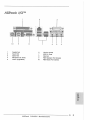
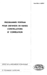
Layout
3
PS2_USB_PWR1 Jumper
ATX Power Header (ATXPWR1)
CPU Heatsink Retention Module
CPU Socket
CPU Fan Connector (CPU_FAN1)
North Bridge Controller
184-pin DDR DIMM Slots (DDR D1MM1- 2)
Secondary IDE Connector (IDE2, Black)
Primary IDE Connector (IDE1,Blue)
ASRock Graphics Interface Slot (AGP1)
South Bridge Controller
Chassis Fan Connector (CHA_FAN1)
Floppy Connector (FLOPPY1)
4
5
6
7
15
16
Chassis Speaker Header (SPEAKER1)
Infrared Module Header (IR1)
17
COM Port Header (COM1)
Clear CMOS (CLRCMOSO, 2-pin jumper)
18
19
20
21
USB 2.0 Header (USB45, Blue)
AMR Slot (AMR1)
BIOS FWH Chip
22
23
24
PCI Slots (PC11-3)
JL1 Jumper
JR1 Jumper
25
Front Panel Audio Header (AUDI01)
26
27
Internal Audio Connector: AUX1 (White)
Internal Audio Connector: CD1 (Black)
System Panel Header (PANEL1)
ASRock P4i45GV Motherboard
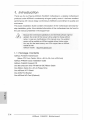
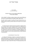
ASRock S/O™
Parallel Port
RJ-45 Port
Game Port
Microphone In (Pink)
Line In (Light Blue)
6
Line Out (Lime)
7
8
9
USB 2.0 Ports
VGA Port
PS/2 Keyboard Port (Purple)
10
PS/2 Mouse Port (Green)
ASRock P4i45GV Motherboard
- 3
II
1. Introduction
Thank you for purchasing ASRock P4i45GV motherboard, a reliable motherboard
produced under ASRock's consistently stringent quality control. It delivers excellent
performance with robust design conforming to ASRock's commitment to quality and
endurance.
This Quick Installation Guide contains introduction of the motherboard and step-bystep installation guide. More detailed information of the motherboard can be found in
the user manual presented in the Support CD.
Because the motherboard specifications and the BIOS software might be
A
updated, the content of this manual will be subject to change without
notice. In case any modifications of this manual occur, the updated
version will be available on ASRock website without further notice.
You may find the latest memory and CPU support lists on ASRock
website as well.
ASRock website
http://www.asrock.com
1.1 Package Contents
ASRock P4i45GV Motherboard
(Micro ATX Form Factor: 9.6-in x 8.2-in, 24.4 cm x 20.8 cm)
ASRock P4i45GV Quick Installation Guide
ASRock P4i45GV Support CD
One 80-conductor Ultra ATA 66/100 IDE Ribbon Cable
One Ribbon Cable for a 3.5-in Floppy Drive
One ASRock I/O™ Shield
One COM Port Bracket
One ASRock MR Card (Optional)
ASRock P4i45GV
Motherboard
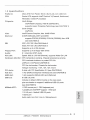
1.2 Specifications
Platform:
Micro ATX Form Factor: 9.6-in x 8.2-in, 24.4 cm x 20.8 cm
CPU:
Socket 478, supports Intel® Pentium"4 (Prescott, Northwood,
Willimate) / Celeron® processor
Chipsets:
North Bridge:
Intel® 845GV chipsets, FSB @ 533/400 MHz,
supports Hyper-Threading Technology (see CAUTION 1)
South Bridge:
Intel® ICH4
VGA:
Intel® Extreme Graphics, Max. 64MB VRAM
Memory:
2 DDR DIMM slots, DDR1 and DDR2
supports PC2700 (DDR333) /РС2100 (DDR266), Max. 2GB
(see CAUTION 2)
IDE:
IDE1: ATA 100 / Ultra DMA Mode 5
IDE2: ATA 100 / Ultra DMA Mode 5
Supports up to 4 IDE devices
Floppy Port:
Supports up to 2 floppy disk drives
Audio:
5.1 channels AC'97 Audio
PCI LAN:
Speed: 802.3u (10/100 Ethernet), supports Wake-On-LAN
Hardware Monitor: CPU temperature sensing, Chassis temperature sensing
CPU overheat shutdown to protect CPU life
(ASRock U-COP)(see CAUTION 3)
CPU fan tachometer, Chassis fan tachometer
Voltage monitoring: +12V, +5V, +3V, Vcore
PCI slots:
3 slots with PCI Specification 2.2 (see CAUTION 4)
AGI slot:
1 AGI [ASRock Graphics Interface] slot (see CAUTION 5)
AMR slot:
1 slot, supports ASRock MR card (Optional)
USB 2.0:
6 USB 2.0 ports:
includes 4 default USB 2.0 ports on the rear panel,
plus one header to support 2 additional USB 2.0 ports
(see CAUTION 6)
ASRock I/O™:
1 PS/2 mouse port, 1 PS/2 keyboard port,
1 parallel port: ECP/EPP support, 1 VGA port
1 RJ 45 port, 4 default USB 2.0 ports
1 Game port
Audio Jack: Line Out / Line In / Microphone In
ASRock P4i45GV
Motherboard
BIOS:
A M I legal BIOS
S u p p o r t s "Plug a n d Play"
A C P I 1.1 c o m p l i a n c e w a k e up e v e n t s
Supports jumperfree
S M B I O S 2.3.1 s u p p o r t
C P U frequency stepless control
(only for a d v a n c e d u s e r s ' r e f e r e n c e , s e e C A U T I O N 7)
OS:
Microsoft® Windows® 9 8 S E / M E / 2 0 0 0 / X P compliant
CAUTION!
1.
About the setting of "Hyper Threading Technology", please
2.
This motherboard will support PC2700(DDR333) at FSB 533MHz.
3.
While CPU overheat is detected, the system will automatically shutdown-
check page 23 of the User Manual in the support CD.
Please check if the CPU fan on the motherboard functions properly before
you resume the system. To improve heat dissipation, remember to spray
thermal grease between the CPU and the heatsink when you install the PC
system.
4.
Because the installed AMR card will occupy the same external connecting
position with the PCI card installed in "PCI3" slot, you will no be able to
install any PCI card in J PCI3" slot if an AMR card has already been
installed in the AMR slot.
5.
The AGI [ASRock Graphics Interface] slot is a special design that only
supports compatible AGP VGA cards. For the information of the compatible
AGP VGA cards, please refer to the "Supported AGP VGA Cards List" on
page 7. For the proper installation of AGP VGA card, please refer to the
installation guide on page 11.
6.
Power Management for USB 2.0 works fine under Microsoft® Windows®
XP SP1/2000 SP4. It may not work properly under Microsoft® Windows 0
98/ME. Please refer to Microsoft^ official document at
http://www.microsoft.com/whdc/hwdev/bus/USB/USB2support.mspx
7.
Although this motherboard offers stepless control, it is not recommended
to perform over-clocking. Frequencies other than the recommended CPU
bus frequencies may cause the instability of the system or damage the
CPU.
m
Я
<Q
.
5»
=r
|| 6
ASRock
P4i45GV
Motherboard
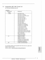
1.3
Supported AGP VGA Cards List
(for Windows 2000/Windows XP)
I. AGP 4X
Graphics Chip
Model Name
Vendor
n-VIDIA
ASUS AGP-V7100
ASUS AGP-V71OOPRO
ASUS AGP-V7100 MAGIC / 32M
ASUS AGP-V7700Ti
ASUS AGP-V8170DDR
ASUS AGP-V8170SE / LP
ASUS AGP-V8200 T2
ASUS AGP-V8200 T5
ASUS AGP-V8440
ASUS AGP-V8460 Ultra
GAINVYARD- GF3-TI500/64M
GAINWARD- GF3-TI500/128M
lnno3D GeForce2 MX400
Leadtek WinFast A170 TH
Leadtek WinFast A170 DDR
Leadtek WinFast A250LE TD
Leadtek WinFast GeForce2 MX MX64
Leadtek WinFast GeForce2 H MX400
MSI- GF4-MX440SE
PROLINK GF4-MX440
SPARKLE GF4-MX440
ATI
Gigabyte GV-AP64D
Gigabyte GV-AP64D-H
Gigabyte GV-AR64S-H
POWERCOLOR RADEON 9000
POWERCOLOR RADEON 9100
TRANSCEND TS64MVDR7
SiS
SYNNEX GCM-SiS315EA32
For the latest updates of the supported AGP VGA cards list, please visit
ASRock website for details.
ASRock website:
http://www.asrock.com/support/index.htm
-C
и
D>
С
ш
ASRock P4i45GV
Motherboard
II. AGP 8X
Graphics Chip
Model Name
Vendor
ALBATRON GF4-MX440 64M
n-VIDIA
AOPEN Aeolus FX5600S-DV128
AOPEN Aeolus FX5200-V128
ASUS AGP-V9180
ASUS AGP-V9280 VIEDO SUITE
ASUS AGP-V9520 MAGIC/T
ASUS V9900
ASUS V9900 ULTRA
ELSA-GLADIC 518
ELSA-GLADIC 518 P
lnno3D GeForce FX5600
LEADTEK A280 LE
LEADTEK A340TDH
MSI T14800SE-VTD8X
PALIT GF4 MX440 8X 64MB
PROLINK GeForceFX5900
PROLINK GF4-TI4200
SPARKLE GF4-MX440-8X
ATI
CLUB3D ATI R9800
Gigabyte GV R9000 PRO
Gigabyte RADEON 9500
Gigabyte RADEON 9700 PRO
POWER COLOR 9200
SAPHIRE RADEON 9200-128MB
POWER COLOR XABRE600
SiS
For the latest updates of the supported AGP VGA cards list, please visit
ASRock website for details.
ASRock website:
http://www.asrock.com/support/index.htiri
ASRock P4i45GV Motherboard
2.
Installation
Pre-installation Precautions
Take note of the following precautions before you install motherboard components or change any motherboard settings.
1.
Unplug the power cord from the wall socket before touching any
component. Failure to do so may cause severe damage to the
motherboard, peripherals, and/or components.
2.
To avoid damaging the motherboard components due to static
electricity, NEVER place your motherboard directly on the carpet
or the like. Also remember to use a grounded wrist strap or touch
a safety grounded object before you handle components.
3.
Hold components by the edges and do not touch the ICs.
4.
Whenever you uninstall any component, place it on a grounded
antstatic pad or in the bag that comes with the component.
2.1
CPU Installation
Step 1.
Unlock the socket by lifting the lever up to а 90° angle.
Step 2.
Position the CPU directly above the socket such that its marked corner
matches the base of the socket lever.
Step 3.
Carefully insert the CPU into the socket until it fits in place.
The CPU fits only in one correct orientation. DO NOT force the CPU into the
socket to avoid bending of the pins.
Step 4.
When the CPU is in place, press it firmly on the socket while you push
down the socket lever to secure the CPU. The lever clicks on the side
tab to indicate that it is locked.
Step 5.
Install CPU fan and heatsink. For proper installation, please kindly refer to
the instruction manuals of your CPU fan and heatsink vendors.
«
D>
С
LU
ASRock P4I45GV
Motherboard
9
II
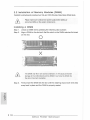
2.2 Installation of Memory Modules (DIMM)
P4i45GV motherboard provides two 184-pin DDR (Double Data Rate) DIMM slots.
Please make sure to disconnect power supply before adding or
A
removing DIMMs or the system components.
Installing a DIMM
Step 1.
Unlock a DIMM slot by pressing the retaining clips outward.
Step 2.
Align a DIMM on the slot such that the notch on the DIMM matches the break
on the slot.
О
A
Step 3.
The DIMM only fits in one correct orientation. It will cause permanent
damage to the motherboard and the DIMM if you force the DIMM into
the slot at incorrect orientation.
Firmly insert the DIMM into the slot until the retaining clips at both ends fully
snap back in place and the DIMM is properly seated.
m
э
<Q
«
:x
|| i o
ASRock P4i45GV
Motherboard
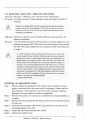
2.3 Expansion Slots (PCI, AMR a n d AGI Slots)
There are 3 PCI slots, 1 AMR slot, and 1 AGI slot on this motherboard.
PCI slots: PCI slots are used to install expansion cards that have the 32-bit PCI
interface.
Because the installed AMR card will occupy the same external connecting
position with the PCI card installed in "PCI3" slot, you will no be able to
install any PCI card in "PCI3" slot if an AMR card has already been
installed in the AMR slot.
AMR slot: AMR slot is used to insert an ASRock MR card (optional) with v.92
Modem functionality.
AGI slot:
The AGI [ASRock Graphics Interface] slot is a special design that only
supports compatible AGP VGA cards. For the information of the compatible AGP VGA cards, please refer to the "Supported AGP VGA Cards List"
on page 7.
Ł
To install the system with an add-on AGP VGA card, you must make
sure to install the driver of add-on AGP VGA card before you install the
onboard VGA driver. If the onboard VGA driver has already been installed before you install the add-on AGP VGA card, the system will
automatically set the onboard VGA as the primary graphics adapter. In
that case, if you want to install the add-on AGP VGA card, you need to
remove the onboard VGA driver first, and then install the add-on AGP
VGA card and its driver. For the detailed instruction, please refer to the
documents in the Support CD, "AGI Slot Installation Guide (for Windows
2000)' and "AGI Slot Installation Guide (for Windows XP)", which are
located in the folder at the following path:
.Л Easy Dual Monitor
Installing an expansion c a r d
Step 1.
Before installing the expansion card, please make sure that the power
supply is switched off or the power cord is unplugged. Please read the
documentation of the expansion card and make necessary hardware
settings for the card before you start the installation.
Step 2.
x:
Remove the system unit cover (if your motherboard is already installed in a
to
"5>
С
chassis).
Step 3.
Remove the bracket facing the slot that you intend to use. Keep the screws
for later use.
Step 4.
Align the card connector with the slot and press firmly until the card is
completely seated on the slot.
Step 5.
Fasten the card to the chassis with screws.
Step 6.
Replace the system cover.
ASRock P4I45GV
Motherboard
1 1 II
2.4 "Easy Dual Monitor"
Thanks to ASRock patented AGI8X Technology, this motherboard supports
Easy Dual Monitor upgrade. With the internal onboard VGA and the external
add-on AGP VGA card, you can easily enjoy the benefits of Dual Monitor
feature. For the detailed instruction, please refer to the document at the
following path in the Support CD:
.A Easy Dual Monitor
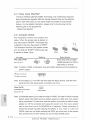
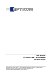
2.5 Jumpers Setup
The illustration shows how jumpers are
setup. When the jumper cap is placed on
pins, the jumper is "SHORT'. If no jumper cap
is placed on the pins, the jumper is "OPEN".
% %
The illustration shows a 3-pin jumper whose
pin1 and pin2 are "SHORT' when jumper cap
is placed on these 2 pins.
Short
Jumper
PS2_USB_PWR1
(see P.2,,N0.1)
Setting
Description
12
JL3
ИОЗ°)
Short pin2, pin3 to enable
(o]o_o]
+5V
Open
+5VSB
+5VSB (standby) for PS/2 or
USB wake up events.
Note: To select +5VSB, it requires 2 Amp and higher standby current provided by
power supply.
JL1 (see
p.2, No. 23)
JR1
JL1
Note: If the jumpers JL1 and JR1 are short (see the figure above), both the front
panel and the rear panel audio connectors can work.
Clear CMOS
(CLRCMOSO, 2-pin jumper)
[Q|Q]
2-pin
jumper
(see p.2, No. 18)
31
Note: CLRCMOSO allows you to clear the data in CMOS. The data in CMOS includes
system setup information such as system password, date, time, and system
и
ЗГ
setup parameters. To clear and reset the system parameters to default setup,
please turn off the computer and unplug the power cord, then use a jumper
cap to short the pins on CLRCMOSO for 3 seconds. Please remember to
remove the jumper cap after clearing the CMOS. If you n e e d to clear the
CMOS when you just finish updating the BIOS, you must boot up the system
first, and then shut it down before you do the clear-CMOS action.
|| 1 2
ASRock
P4I45GV
Motherboard
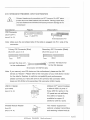
2.6 Onboard Headers and Connectors
Onboard headers and connectors are NOT jumpers. Do NOT place
Ł
jumper caps over these headers and connectors. Placing jumper caps
over the headers and connectors will cause permanent damage of the
motherboard!
_Figure
Connector
Description
FDD Connector
(33-pin FLOPPY1)
КPINI
(seep.2, No. 13)
FLOPPY1
the red-striped side to Pin1
Note: Make sure the red-striped side of the cable is plugged into Pin1 side of the
connector.
Primary I D t Connector (Blue)
Secondary IDE Connector (Black)
(39-pin IDE1, see p.2, No. 9)
(39-pin IDE2, see p.2, No. 8)
PINT
IDE1
IDE2
IPINl
connect the blue end
to the motherboard
{j^jf
connect the black end
to the IDE devices
80-conductor ATA S6/100 cable
Note: If you use only one IDE device on this motherboard, please set the IDE
device as "Master". Please refer to the instruction of your IDE device vendor
for the details. Besides, to optimize compatibility and performance,
please connect your hard disk drive to the primary IDE connector (IDE1,
blue) and CD-ROM to the secondary IDE connector (IDE2, black).
USB 2.0 Header
(9-pin USB45)
(seep.2, Mo. 19)
.łJSąjwR
5
1
P-5
6
4
op 5 о
919
ASRock I/O™ accommodates
4 default USB 2.0 ports. If
those USB 2.0 ports on the
I/O panel are not sufficient,
this USB 2.0 header is
available to support 2
D>
С
additional USB 2.0 ports.
Infrared Module Header
(5-pin IR1)
(see p.2, No. 16)
This header supports an
,DUf MY
lólólo
il
'РОЛ
ASRock P4i45GV
optional wireless transmitting
and receiving infrared module.
Motherboard
- 13 II
Internal Audio Connectors
These connectors allow you
CD-RGND-
(4-pin CD1,4-pin AUX1)
CD1
I
(CD1: see p.2, No. 27)
A JX-RGNDGNDAUX-L-
(AUX1: see p.2, No. 26)
Front Panel Audio Header
AUX1
U
BAOOUT-R
(9-pin A U D I 0 1 )
IBACKOUT-L
(see p.2, No. 25)
AUD-OUT-L
'GND
AJD-OUL-P
MIC-POWTR
MIC
i
(9-pin PANEL1)
This is an interface for front
panel audio cable that allows
control of audio devices.
This header accommodates
PLED+
.PLEDI PWRBTN#
I&ND
dates several system front
и
(see p.2, No. 14)
a CD-ROM, DVD/ROM, TV
tuner card, or MPEG card.
convenient connection and
n
System Panel Header
to receive stereo audio input
from sound sources such as
panel functions.
'DUMMY
'RESET*
1 GMD
HDLEDHDLED +
Chassis Speaker Header
(4-pin SPEAKER 1)
(see p.2, No. 15)
Chassis Fan Connector
(3-pin CHAJ=AN1)
f
Please connect the chassis
SPEAKER
DUMMY
DUMMY
O-- 12V
o-- CHA FAN
speaker to this header.
Please connect a chassis fan
SPEED
cable to this connector and
match the black wire to the
(see p.2, No. 12)
ground pin.
CPU Fan Connector
(3-pin CPU_FAN1)
O" - G N D
О
И 2V
O - -CPU_FAN_SPEED
Please connect a CPU fan
cable to this connector and
match the black wire to the
(see p.2, No. 5)
ground pin.
m
ATX Power Header
Please connect an ATX power
(20-pin ATXPWR1)
supply to this header.
(see p.2, No. 2)
3
=
ЗГ
=r
COM Port Header
(Э-pin COM1)
(see p.2, No. 17)
This COM port header
RRIDL
|DDTR#1
supports a COM port module.
Jc * i
19 о 9 s г
•FIRTS# 1
IGND
TTXDL
DDCD#1
14
ASRock P4i45GV
Motherboard
3. BIOS
Information
The BIOS Setup Utility is stored in the BIOS FWH chip. When you start up the
computer, please press <F2> during the Power-On-Self-Test (POST) to enter the
BIOS Setup Utility; otherwise, POST continues with its test routines. If you wish to
enter the BIOS Setup Utility after POST, please resume the system by pressing <Ctl>
+ <Alt> + <Delete>, or pressing the reset button on the system chassis For the
detailed information about the BIOS Setup Utility, please refer to the User Manual
(PDF file) contained in the Support CD.
4. Software Support CD
information
This motherboard supports various Microsoft® Windows® operating systems: 98 SE/
ME / 2000 / XP. The Support CD that came with the motherboard contains necessary
drivers and useful utilities that will enhance motherboard features.
To begin using the Support CD, insert the CD into your CD-ROM drive. It will display
the Main Menu automatically if "AUTORUN" is enabled in your computer. If the Main
Menu does not appear automatically, locate and double-click on the file
"ASSETUP.EXE" from the "BIN" folder in the Support CD to display the menus.
"PC-DIY Live Demo"
ASRock presents you a multimedia PC-DIY live demo, which shows you a
step-by-step guide to install your own PC system. To see this demo program,
you can run Microsoft® Media Player® to play the file, which can be found
through the following path:
.Л MPEGAV \ AVSEQ01 .DAT
ASRock P4i45GV
Motherboard