1
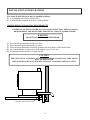
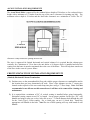
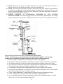
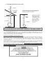
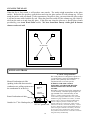
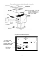
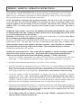
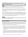
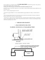
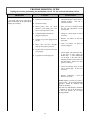
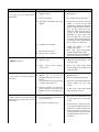
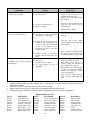
Avent
WOOD PELLET STOVE
OWNER’S MANUAL
Installation – Operation – Maintenance Instructions
NOTE: THESE INSTRUCTIONS MUST BE SAVED for future reference
HOT WHILE IN OPERATION -KEEP CHILDREN, CLOTHING AND FURNITURE AWAY - CONTACT MAY
CAUSE SKIN BURNSPLEASE READ THIS ENTIRE MANUAL BEFORE INSTALLATION AND USE OF THIS
PELLET BURNING STOVE. FAILURE TO FOLLOW THESE INSTRUCTIONS MAY RESULT IN PROPERTY
DAMAGE, BODILY INJURY OR EVEN DEATH.
IMPORTANT: Always contact your local dealer/installer with questions before contacting the factory.
When you call have your serial number, purchase date, who installed the unit and a list of questions.
9 When installing your Avent Wood Pellet stove, particular attention needs to be made in regards to fire
protection. If the unit is not properly installed, a house fire may result. For your safety, follow the
installation and operation instructions provided. Contact local building or fire officials about restrictions
and installation inspection requirements in your area.
9 Read the operations and fuel section of this manual before plugging in your unit.
9 Always unplug the unit before attempting any service work.
9 Do not connect the unit to a chimney flue already serving another appliance.
9 When installing the chimney pipe to the unit, it is important to remember that the unit operates on a
positive pressure and the chimney on a positive pressure. All chimney connections, elbows and fittings
must be airtight. (proper venting practices must be followed. Consult with a venting professional)
9 Ashes must be disposed of in a metal container with a tight fitting lid.
9 All minimum clearances to combustibles must be followed.
9 The Avent Wood Pellet Stove is tested for operation with wood pellets with ash content of no more than
2%. It is recommended that wood pellets with an ash content of 1% or less be used for efficient
operation of this unit. For use with wood pellets, cherry pits, olive pits or other pelletized fuel.
9 It is important to use fuel that is clean, dry and consistent. Make sure that your supplier is giving you
the same fuel each time that you purchase. It is recommended that you purchase your entire heating season
supply of fuel at one time so that the fuel will be the same.
9 A voltage surge protector or ground fault outlet is required for this unit. The warranty will be
voided if surge protection is not installed before operating this unit.
9 A grounded outlet must be provided with proper polarity. A constant 115 volt, 60 cycles must be
provided for proper operation or the warranty of this appliance will be forfeited.
9 Special attention needs to be taken to clean out the top heat exchangers of this unit on a regular
basis. The fly ash from the venting settles on the top heat exchangers and must be cleaned off to
keep the unit operating properly. Check for plugging every one-two weeks or when needed.
9 If unit is not operated for extended periods of time (like summer) unplug the unit and disconnect the
battery to assure long life of electrical components.
9 This appliance has been tested to ASTM E1509 ULC C1482standards by OMNI-Test Laboratories, Inc.
9 The authority having jurisdiction (such as municipal building dept., fire dept., fire prevention
bureau, etc.) should be consulted before installation to determine the need to obtain a permit.
9 If smoke detectors are installed close to the appliance, they may go off if the stove door is left open or
if there is not adequate fresh air for the appliance to operate properly.
AMERICAN ENERGY SYSTEMS, INC. GRANTS NO WARRANTY, IMPLIED OR STATED, FOR THE
INSTALLATION OR MAINTENANCE OF THE STOVE AND ASSUMES NO RESPONSIBILITY FOR ANY
CONSEQUENTIAL DAMAGE(S).
AMERICAN ENERGY SYSTEMS, INC. -150 Michigan Street SE - HUTCHINSON, MINNESOTA 55350
Web Site: www.hearthdirect.com
Rev. date 05/05/04
TABLE OF CONTENTS
PAGE
TECHNICAL BULLETIN: IMPORTANCE OF FRESH AIR
3
AVENT TECHNICAL DATA / ESTIMATED FUEL FEED RATE CHART……………….
4
INTRODUCTION & SPECIFICATIONS………….………………………………………....
5
SAFETY STEPS ……………………………………………………………………………...
6
BURNING SOLID FUELS (WOOD PELLETS)………………………...................................
7
UNPACKING YOUR AVENT WOOD PELLET STOVE / FLOOR PROTECTION /
CLEARANCES TO COMBUSTIBLES………………………………………………………
GUIDELINES FOR EXHAUST VENTING SYSTEMS DESIGN……………..……….........
8
9-11
DESIGN GUIDELINES FOR OUTSIDE COMBUSTION AIR CONNECTION…………....
12-13
INSTALLATION CONFIGURATIONS / MOBILE HOME INSTALLATION REQ……….
14
ALCOVE / FREE STANDING STOVE INSTALLATION REQUIREMENTS……………..
15-17
GLASS MAINTENANCE, ADJUSTMENT, REMOVAL AND REPLACEMENT…………
17
CLEANING THE GLASS / STOVE CONTROLS……………………………………………
18-19
PRIMING / LIGHTING / OPERATING INSTRUCTIONS…………………………………..
20
CIRCUIT BOARD FUNCTIONS / SETTING THE DRAFT…………………………………
21
MAINTENANCE INSTRUCTIONS………………………………………………………….
22
SPECIAL CLEANING / OPERATIONAL INSTRUCTIONS………………………………..
23
AUTOMATIC SAFETY FEATURES………………………………………………………...
24
THERMOSTAT INSTALLATION / OPTIONS……………………………………………...
25-26
12 VOLT DC WIRING INSTALLATION……………………………………………………
27
TROUBLE SHOOTING GUIDE……………………………………………………………...
27-29
REPLACEMENT PARTS LIST………………………………………………………………
29
WIRING DIAGRAM / CIRCUIT BOARD FINE TUNE ADJUSTMENTS………………….
30
WARRANTY INFORMATION………………………………………………………………
31
SERVICE RECORD…………………………………………………………………………..
32
WARRANTY REGISTRATION CARD……(IN HARDWARE PACKET)
2
Technical Bulletin
Importance of adequate fresh air
Every home is a slightly different situation and depending on the design of the air movement within the
home, might be easy to distribute heat or very difficult. If you have boiler heat or other non-ducted
central heating this becomes even more of a challenge as adequate circulation within the home and proper
make up air for combustion is lacking because of the design of your central heating system.
When a forced-air system is put into a home that is not designed with proper circulatory patterns, it might
be necessary to add return air ducts or at least vents to get the air moving around the home. Fresh air for
the home and fresh air for combustion will have to be added or the stove or furnace will burn dirty and
efficiency will suffer.
Your dealer needs to assess the fresh air requirements for the home. At a minimum, there should be a 6”
or larger (this should be determined by figuring what the home requires) fresh air vent coming in to a
neutral part of the home to make sure that there is adequate fresh air to the home. Then the 3”make up air
to the unit is required to be provided.
If the wood pellets are not burning correctly you need to address a few things. Are the wood pellets wet
or dirty? If they are, make sure that your wood pellets are cleaned (we have an excellent “E-SIFTER”
product that will do a great job) and below 15 percent moisture. 3-4 percent moisture is ideal.
The most common cause of wood pellets not burning properly is contaminated air or negative pressure in
the home. It can be as simple as the air adjustment not set properly on the side of the stove or it could be
that there is a serious lacking of good quality air in the home caused by negative pressure. If you have
done any remodeling or if this is a newer home, it is a very real possibility that this is happening. Most
basements have negative pressure even if you feel that your home is drafty. This is called the stack or
chimney effect. Excessive positive pressure in the home can also cause problems such as over firing.
If there is a black coating of soot coming into the home it is caused by the reversal of the exhaust that
would normally exit the stove outside being drawn into the home by negative pressure or improperly
installed venting. Depending on your venting configuration this could be aggravated by back drafts, high
wind and cold chimneys.
Sometimes this also occurs if there is an intake for fresh air too close to the exhaust on the outside of the
home or other conditions causing the exhaust to be pulled back into the home.
The first indications of negative pressure affecting the stove occurs app. 3 days after the stove is lit. The
glass gets dirty very easy, the firepot might keep filling up even though you pull the air adjustment out,
and you notice that the venting fills up with soot rapidly. After a few days, the exhaust can no longer
adequately pull out all of the fly ash so it reverses and is pulled into the home. This might happen
through the venting if it is not sealed properly or it might come out when you open the door for
maintenance and also backwards through the air wash system.
This can be easily corrected by adding the fresh air for the home and also for the appliance. It is
imperative that you would have your dealer or installer check the unit out for proper operation to make
sure that there is nothing mechanical wrong with the appliance and then determine your need for proper
fresh air. Your dealer can contact the factory with any questions that he might have.
3
AVENT TECHNICAL DATA
ESTIMATED FUEL FEED RATE CHART
The fuel feed rates shown can vary as much as 30-50% depending on fuel quality.
WOOD PELLETS: Fuel consumption will vary depending on fuel size
Low fuel setting
Medium fuel setting
High
16 ounces per hour
24 ounces per hour
38 ounces per hour
2.5 ounces in a 10 minute test
4 ounces in a 10 minute test
6.4 ounces in a 10 minute test
These fuel consumption feed rates are an approximation. Each unit will vary with the type and size of
the fuel that is being burnt. The most important feed rates to check would be the # 1 setting and the
High setting to make sure that the low and high feeds are proper for the unit. If the feed rates are
drastically different contact your local dealer for circuit board factory adjustments. Do not get alarmed
if the feed rates are not the same as shown. As long as the low fire will stay lit and the high fire does
not overheat the unit and shut it down the unit is performing as it should.
The unit is designed to adapt to different size fuels and consumption circumstances.
If you are experiencing different feed rates than shown you will need to set the fuel feed rate on a lower
or higher setting to adjust for the differences in the fuel feed rate. The size and flow characteristics of
wood pellets vary from year to year and that alone will change the heat output of the unit. There is a
fine tune adjustment that the Reseller can make to the circuit board if the low fire will not stay lit or is
burning too hot. You will need to contact your local Reseller for this adjustment.
It is recommended that when the unit is first installed in the customer’s home that the unit be fired and
run for over an hour to see if the air adjustment is right for the fuel. Making the proper air adjustment
and making sure that proper outside air has been provided will allow the unit to perform properly.
The Avent is certified to burn premium quality wood pellets. Check with your local Reseller before
burning fuels not approved.
NOTE: The factory will not pay warranty service calls on problems that have come up on the
unit when the proper fuel, combustion air requirements and air adjustments have not been
checked.
tdocbeff
DEAR VALUED AVENT OWNER,
We appreciate your decision to help preserve our precious environment by purchasing the Avent Positive
Draft Wood Pellet Appliance. With everyone working together, we can have clean air and renewable
heat for our homes.
Please read this Owners Manual carefully before using this appliance and if you have any questions
contact your local Avent reseller. We appreciate your business and wish you many warm days and nights
with your new Avent Wood Pellet Appliance.
Sincerely,
Mike
Mike Haefner, President
American Energy Systems, Inc.
P.S. You are very important to the success of our business and your referral of our products is very much
appreciated. Many of our Resellers have referral rewards available and I encourage you to ask your local
dealer how to get involved in helping make our country energy self-sufficient. GOOD LUCK !
SPECIFICATIONS
American Energy Systems, Inc., manufacturer of the Avent Wood Pellet Appliances, reserves the right to alter its
products, their specifications and/or price without notice.
Safety tested and EPA exemption tested by OMNI-Test Laboratories, Inc. to ASTM1509, ULC C1482.
Heat Output*
20,500 BTU/HR
Fuel Storage Capacity
20 Lbs.
Width
15.5”
Height with Pedestal
28”
Depth
28”
CLEARANCE TO COMBUSTIBLES
Back Wall
Vertical Termination
w/ 3” Pellet Vent
4” (100mm)
Side
4” (100mm)
Corner
3” (75mm)
Flue to Wall
3” (75mm)
Floor Prot.
6” (150mm) out in front of unit 0” to sides
BTU output will vary, depending on the brand of fuel, size of fuel, quality of fuel and moisture content.
Consult your authorized Avent reseller for information on the best fuel to use to get the best results.
5
SAFETY STEPS
IMPORTANT: Proper installation of this stove is crucial for proper and safe operation. Installing this
product improperly may result in a house fire and personal injury. All applicable building codes for your
location must be followed. In areas where building codes require additional steps to the installation of
this product not included in this manual, the building codes will take precedent and must be followed.
Contact your local building inspector to obtain any necessary permits or inspection guidelines before
installing the product. (This appliance must be installed by a trained professional installer to assure
proper installation and warranty of this product) Warranty Labor and shipping will not be
covered if the unit is not installed by a trained installer.
9 DISCONNECT THE POWER CORD BEFORE SERVICING THIS STOVE! A power surge
protector is required. The unit must be plugged in to a grounded 110 -volt 60 hz or a 12V DC
sealed Battery power source. NEVER use an “unsealed” type battery, nor operate unit on a battery
without a 12 volt 4 ampere in-line fuse on a positive line.
9 Always route the power cord away from the unit. Do not route cord in foot traffic areas. Do not
pinch cord under furniture. Do not add any additional length to the power cord.
9 This product requires simple periodic maintenance for proper operation and long life of the stove.
Read and follow the maintenance schedule closely.
9 The Avent Pellet stove is designed, approved and tested to burn wood pellets. The burning of
other solid fuels such as cord wood in this stove is not permitted. If you are burning fuels not
approved for this appliance it will void the warranty and no service/warranty will be allowed.
The Avent will burn high ash content fuels but will require additional maintenance/cleaning.
9 A working smoke detector must be installed in the same room as this product.
9 Flammable or explosive liquids such as gasoline, naphtha or engine oil must NEVER be used in or
around this stove. These liquids must be stored well away from this stove as the open flame in the
burner chamber could ignite the fumes of such liquids. Do not burn garbage in this unit.
9 According to HUD requirements, when installed in a mobile home, this stove must be grounded
directly to the steel chassis of the mobile home and bolted to the floor.
9 This stove is not intended for use in commercial installations but can be used.
9 The moving parts of this stove are propelled by high torque electric motors. The auger can cause
severe injury to body parts that may get near them. Keep all body parts away from the auger while
the stove is plugged into an electrical outlet. These moving parts may begin moving at any time while
the stove is plugged in.
9 This unit must be installed on a non-combustible surface. Make sure that the unit is level.
9 Do not attempt internal service to the unit when it is burning and or plugged into power.
9 It is a good idea to burn the unit outside for a couple hours before installation to burn off any paint or
oil fumes. (most resellers pre-burn the unit before you receive them, do not worry if your unit has
looks like it has been burnt)
IMPORTANT: It is the customer’s responsibility to make sure the Reliant Appliance is installed with the
proper make up air system and the home is checked for adequate fresh air so that the appliance does not
become the fresh air source for the home.
6
BURNING SOLID FUELS (wood pellets)
Unlike petroleum and natural gas products, solid fuels such as wood pellets create ash as the fuel is
burned. Even with the highly efficient flame your Avent Wood Pellet stove will produce, the solid fuels
used will produce ash. This ash will have to be cleaned out of the stove from time to time. The cleaning
procedure will be discussed later in this manual. You can minimize the amount of cleaning required and
maximize the efficiency of your stove by maintaining the correct draft settings.
The draft setting on your stove may have to be changed from time to time to accommodate your specific
burning conditions. Proper draft setting will be discussed later in this manual. The point we wish to
make here is that your Avent Wood Pellet stove, due to the nature of solid fuels, will require brief
periodic attention. Please do not expect to light your stove and walk away from it until you want to shut it
off in the spring. A few moments of adjustment and cleaning from time to time is an important part of
burning solid fuels.
The Avent Wood Pellet stove has been designed to burn wood pellets that meet the Association of Pellet
Fuel Industries standards. Since these fuels vary greatly in quality and consistency, AES cannot be
responsible for damage done to your stove due to fuel problems. The following are guidelines to using
and selecting proper fuels for your stove.
WOOD PELLETS
9 Be consistent in your wood pellet fuel supplier. Wood Pellets will vary in content and burn
characteristics from supplier to supplier. A consistent supply of wood pellets will require fewer
adjustments to the draft of the stove.
9 Check your wood pellets for foreign objects. Your stove warranty will not cover damage done to your
stove due to foreign objects in the fuel supply.
9 Store your wood pellets in a dry place to prevent them from absorbing excess moisture.
9 Vacuum the hopper out after every 6-7 bags to eliminate buildup of sawdust. More often if the wood
pellets are poor quality. If sawdust is a problem you will have to screen each bag of fuel for a
consistent feed.
9 Wood Pellets vary from supplier to supplier in ash content from less than 1% to 3% or more. Low ash
content pellets will allow you to burn the stove longer between cleanings. Only wood pellets
manufactured to the Association of Pellet Fuel Industries (A.P.F.I.) standard for residential pellet
fuels are recommended. Look for A.P.F.I. registration number on the back of pellets. Consult your
local Avent Wood Pellet reseller for more information on approved wood pellet fuel.
9 Do not place or store any fuel within the space heater installation clearances or within the space
required for filling the fuel hopper and ash removal. It is strongly recommended not to keep a supply
of wood pellets over the summer months. Moisture will build up and cause problems in the fall with
your appliance operation. Make sure that your supplier is not selling you left over fuel or fuel that has
been out in the rain.
7
UNPACKING YOUR AVENT WOOD PELLET STOVE
When you receive your Avent Wood Pellet Stove be careful to inspect all parts and components to make
sure that nothing was damaged or lost in shipment. If there was shipping damage, be sure to report it to
your Avent Wood Pellet reseller, or the shipping company that delivered your unit. Freight damage
claims must be made to the Freight Company immediately. If parts are missing contact your local
Avent Wood Pellet reseller or contact the factory right away. Your satisfaction is our top priority.
To uncrate your Avent Wood Pellet Stove:
1) Cut the banding straps and open the carton lid. The carton is stapled to the wood pallet so it will be
necessary to pull the cardboard loose from the pallet. Remove the crating box carefully lifting up over
the top of the unit. Be careful not to scratch the unit with the staples. Remove the wood blocks and
plastic. We strongly urge you to recycle the packaging materials to help protect the environment.
FLOOR PROTECTION
The Avent Wood Pellet Freestanding Stove may be installed on a combustible floor, with proper floor
protection, or on a masonry hearth. The hearth or non-combustible floor protector must extend a
minimum of (6) six inches (152mm) in front of the unit and beyond each side of the fuel loading and ash
Removal openings.
CLEARANCES TO COMBUSTIBLES
The stove must be installed with the following minimum clearances to side and back wall combustible
materials. NOTE: These are minimum clearances to combustible walls established by the testing lab.
The amount of room needed on the left side of the unit to access the electrical panel is (6) six inches.
D
C
E
A=4” B=4”
C=4” D=3”
E=8.5”
A= Left
D
B= Right
Residential/Mobile Home
Horizontal + Vertical
Corner Installation
Residential/ Mobile Home
Vertical Installation
8
The side and top clearance are to be used when
installing the Avent Wood Pellet stove into an alcove
as shown to the left and below.
Minimum Alcove Height is 56”
(1425mm)
Maximum Alcove Depth is 36”
(915mm)
28”
Minimum Alcove width is 27.5”
(700mm)
14”
28”
6”
min.
HEARTH PROTECTION
GUIDELINES FOR EXHAUST VENTING SYSTEMS DESIGN
It is recommended that only an authorized Avent Wood Pellet installer install your wood pellet stove. The following
installation guidelines must be followed to ensure conformity with both the safety listing of this stove and to local building
codes.
9
A listed 3” or 4” type “PL” pellet vent exhaust system must be used for FREESTANDING installation and attached to the
pipe connector provided on the top of the stove. Use a 3” to 4” adapter for 4” pipe. A cap must be used at the termination
of type “L” vent chimneys. Existing approved 4, 6 and 8” wood stove pipe may be used with adaptors to 3 inch pellet vent
pipe as shown in the installation instructions. The pipe adaptors must be provided by the venting manufacturer.
9
Do not terminate vent in any enclosed or semi-enclosed area, such as; carports, garage, attic, crawl space, under a sundeck
or porch, narrow walkway or closed area, or any location that can build up a concentration of fumes such as a stairwell,
covered breezeway etc.
9
Vent surfaces can get hot enough to cause burns if touched by children. Non-combustible shielding or guards may be
required. DO NOT INSTALL A FLUE DAMPER IN THE EXHAUST VENT OF THIS UNIT.
9
Termination must exhaust above air inlet elevation. It is required that at least 5 ft. of vertical pipe be installed when
the appliance is vented directly through a wall or in a basement. This will create some natural draft to prevent the
possibility of smoke or odor during appliance shutdown and to keep exhaust from causing a nuisance or hazard from
exposing people or shrubs to high temperatures. In any case, the safest and preferred venting method is to extend the vent
through the roof. DO NOT CONNECT THIS UNIT TO A CHIMNEY FLUE SERVING ANOTHER APPLIANCE.
9
9
Distance from doors and windows, gravity or ventilation air inlet into building:
Not less that 4 ft. / 1.2 m below, 4 ft. / 1.2 m horizontally from, 1 ft. / 305 mm above (This does not apply if the
Windows are non-opening or have been fixed so they cannot open.)
9
Distance from bottom of termination and grade – 1 ft. / 305 mm minimum. This is conditional upon the plants and nature
of grade surface. The exhaust gases are not hot enough to ignite grass, plants or shrubs located in the vicinity of the
termination. The grade surface must not be a lawn. Distance from bottom of termination and public walkway is 7ft. /2.1m
minimum.
9
Distance to combustible materials – 2 ft. / 610 mm. This includes adjacent building, fences, protruding parts of the
structure, roof overhang, plants and shrubs, etc.
9
It is recommended that a single or double clean-out “tee”, for cleaning the vent in both directions, be installed at every 900
junction to enable collection of fly ash and to permit periodic cleaning of the exhaust system. 900 elbows accumulate fly
ash and soot thereby reducing exhaust flow and performance of the stove.
9
Total length of horizontal vent must not exceed 36” (3 ft.) / 915 mm. All joints in the vent system must be fastened by at
least 3 screws, and all joints must be sealed with RTV silicone sealer to be airtight.
9
When venting into an existing masonry or factory built chimney, the chimney must be cleaned, with all creosote removed.
The chimney must be a type suited for solid fuel. WARNING: The chimney and the chimney connections must be kept
clean and in good condition.
9
The “PL” vent or single wall stainless exhaust system must be installed so as to be GAS TIGHT! The vent manufacturer’s
installation procedures must be followed. In addition, pipe connections, joints and all pipe seams within the home should
be sealed with high temperature RTV silicone sealer. Single wall venting can only be used within the dwelling.
9
A minimum of 3 feet/915mm horizontally from the center line of any regulator/meter assembly
9
A minimum of 3 feet/915mm from any non mechanical air supply inlet to the building
9
A minimum of 6 feet/1830mm from any mechanical air supply inlet to the building
NOTE: Local building codes or regulations may require different clearances.
Special note for Canadian Installations:
Where the venting may pass through a wall, or partition of combustible materials, the installation shall
conform to CAN/CSA-B365. The wall thimble shall be properly sealed with Hi-Temperature silicone to
prevent any moisture or vapor from building up. Make sure that there are no air leaks.
Clearances to venting and also clearances to combustibles for the appliance can only be reduced by means
approved by the regulatory authority.
EXHAUST VENTING SYSTEM PRECAUTIONS:
Soot and Flyash: Formation and need for removal- The products of combustion will contain small particles
of flyash. The flyash will collect in the exhaust venting system and restrict the flow of the flue gases.
Incomplete combustion, such as occurs during startup, shutdown, or incorrect operation of the room heater
will lead to some soot formation which will collect in the exhaust venting system. The exhaust venting system
should be inspected at least once every year to determine if cleaning is necessary. It is recommended to
check the venting system monthly to assure proper operation of the appliance.
10
GUIDELINES FOR EXHAUST VENTING SYSTEMS DESIGN, CONT……
To determine whether a 3” or 4” exhaust system should be used, follow the guidelines below:
1) Determine the “equivalent pipe length” for each component used according to the comparison chart
below. Add the “equivalent pipe length” of all components to get the “total equivalent pipe length”.
2) Determine the altitude at which you are installing the stove.
3) Cross-reference the “total equivalent pipe length” and the altitude using the graph below.
NOTE: The “total equivalent pipe length” should not exceed 20 feet.
Component
Equivalent Length
Horizontal Straight Pipe
Actual Length in ft. x 1.0
Horizontal Pipe
=
1 x (2+1) =
3 ft.
Vertical Straight Pipe
Actual Length in ft. x 0.5
Vertical Pipe
=
0.5 x 8 =
4 ft.
5.0 feet
90 Degree Tee
=
2x5=
10 ft.
3.0 feet
45 Degree Tee
=
1x3=
3 ft.
TOTAL
=
0
90 Elbow or Tee
0
45 Elbow
Equivalent Pipe Length
20 ft.
NOTE: These are guidelines only. Proper venting is accomplished by design and common sense. In most
installations 3 inch diameter venting is adequate. If it does not vent properly you will have to change it to 4”.
CRITERIA FOR SELECTING PIPE DIAMETER
MAXIMUM
25
20
4” DIAMETER ONLY
15
10
3” OR 4” DIAMETER
5
0
0
0
2
2
4
4
6
6
8
8
ALTITUDE X 1,000 FEET
11
10
10
12
12
DESIGN GUIDELINES FOR OUTSIDE COMBUSTION AIR CONNECTION
OUTSIDE MAKE-UP AIR FOR COMBUSTION IS REQUIRED ON ALL INSTALLATIONS
1) For FREESTANDING installations with horizontal through-the-wall exhaust, it is REQUIRED that
the stove combustion air intake be connected to a fresh air intake outside. If the home is newer or has
been tightly insulated it is imperative to the operation of the unit to install outside combustion air. If
you do not, then an additional 6 inch intake into the furnace room in the basement is required.
2) Connection to outside the house is REQUIRED for mobile home installations.
3”
3) The outside air tubing must be a minimum of 3” inside diameter. It is recommended that the tubing
be non-combustible materials but is not required.
4) If the air inlet is connected to the outside, it MUST be terminated with a vertical 90-degree bend
(down) or with a wind hood. Failure to do so could result in a burn back during high winds blowing
directly up the air inlet during a simultaneous power failure (see diagram above).
5) It is important not to terminate the inlet of the fresh air intake too close to the venting outlet for the
smoke. It is recommended that the inlet for the fresh air is a minimum of 3 feet away from the venting
outlet and at least 1-2 feet below.
6) Blockage, excessive length, or bends in the air intake pipe will starve the stove of combustion air. A
90-degree bend is equivalent in restriction to approximately 30 inches of straight inlet pipe.
12
OUTSIDE AIR DIAGRAM
Outside air hookup is located on the
back panel of the pedestal fan
housing.
WARNING: DO NOT RESTRICT
OR OTHERWISE COVER THE
FAN INTAKE EXCEPT AS
SHOWN FOR THE OUTSIDE AIR
HOOKUP.
The outside air must be directly
connected to the appliance. Outside
air may be taken from a vented crawl
space. Outside air cannot be taken
from an attic, garage or any other
enclosed space within the building.
7/16” bolt to the steel chassis
(only on mobile home installation)
Note: The outside air tube will only
cover a portion of the fan intake. Air
will be drawn from outside and inside
the home.
Connect a flexible hose to the outside
air adaptor plate and route the hose as
directed in the diagram.
WARNING: ROOM AIR STARVATION CAN CAUSE THE APPLIANCE TO MALFUNCTION,
BURN DIRTY AND SHUT DOWN. IF YOU DO NOT INSTALL ADEQUATE FRESH AIR
SUPPLY, RUNNING EXHAUST FANS, ICING UP OF CRACKS, ETC. WILL CAUSE THE
UNIT TO NOT BURN PROPERLY. FRESH AIR IS REQUIRED FOR THIS APPIANCE TO
OPERATE PROPERLY.
13
INSTALLATION CONFIGURATIONS
The Avent Wood Pellet Stove may be installed as follows:
1) A freestanding unit (with a pedestal only)
2) A built-in heater mounted in an alcove with a pedestal
MOBILE HOME INSTALLATION REQUIREMENTS
IN ADDITION TO THE STANDARD INSTALLATION INSTRUCTION, THE FOLLOWING
REQUIREMENTS ARE MANDATORY FOR INSTALLATION IN A MOBILE HOME:
WARNING
DO NOT INSTALL IN SLEEPING ROOM
1)
2)
3)
4)
5)
Stove must be permanently bolted to the floor.
Stove must have permanent outside air source.
Stove must be permanently electrically ground to the steel chassis of the mobile home.
All vertical chimney vent must have wall supports every (5) five feet.
All exhaust systems must have a spark arrestor.
CAUTION
THE STRUCTURAL INTEGRITY OF THE MOBILE HOME FLOOR, WALL AND CEILING
MUST BE MAINTAINED.
CHECK WITH YOUR LOCAL BUILDING OFFICIAL AS OTHER CODES MAY APPLY.
7/16” bolt to the steel chassis
14
ALCOVE INSTALLATION REQUIREMENTS
The Avent Wood Pellet is approved for the standard alcove height of 56 inches, or for a reduced alcove
height with a minimum of 14 inches from the top of the stove (clearance for opening top lids). The
maximum alcove depth is 36 inches and the listed side clearances are a minimum of 4 inch. The 14”
56”
Minimum
4” minimum
clearance is only needed for opening the back lid.
The stove is approved for limited horizontal and vertical exhaust. It is required that the exhaust goes
vertically for a minimum of 2 feet above the unit before a 90 degree elbow is installed and after the
venting exits the home it must be terminated above the eave of the house. This will help draw smoke out
of the stove in the event of a power failure.
FREESTANDING STOVE INSTALLATION REQUIREMENTS
(Limited) Horizontal Exhaust Termination:
1) Position stove on the noncombustible floor pad with the proper clearances to combustibles and in
the location that you have determined will work. Place a Pipe Adaptor over the 3” starter pipe
located on the top back of the stove and clamp into place using a 3” hose clamp. Note: It is not
recommended to use silicone on this connection as it will have to be removed for cleaning and
maintenance.
2) It is required that a minimum of 24” of vertical venting is installed before going horizontally.
Horizontal venting cannot exceed 36” in length. Locate proper position for the type “PL” wall
thimble and using a saber saw or key- hole saw to cut a 7 1/4-inch diameter hole through the wall
for the 3-inch Type L Pellet venting. For a 4-inch pipe, cut an 8 1/4-inch hole. Install the
appropriate wall thimble in the hole. Note:The size of hole opening will vary with brand of wall
thimble.
15
3) NOTE: Make sure that you leave enough clearance between the wall and the back of the unit so
that you will be able to install the outside air and work on the intake fan.
4) NOTE: In cold climates running the venting on the outside of the home without an insulated chase
way will cause condensing, creosote buildup, staining of siding and poor operation of the unit. It is
strongly recommended that all venting is run on the interior of the home and if that is not possible,
install venting in an insulated chase way.
5) INSTALL VENTING AT CLEARANCES SPECIFIED BY THE VENTING
MANUFACTURER. American Energy Systems does not assume responsibility for the venting
design or installation of the product. Diagrams are shown as a reference and a guide for clearances.
90 degree
elbow or
clean out tee
5’
Minimum
Height
INSTALLATION INSTRUCTIONS: Conventional & Mobile Home
NOTE: The following are general instructions for installing this appliance. The vent pipe
manufacturer’s instructions should be followed for the brand of venting being used.
• Before drilling or cutting holes, select the proper location of the appliance.
• Determine location of combustibles, ceiling rafters, wall studs or floor joists before cutting holes.
• Be careful not to drill or cut into any water or electrical lines as damage or injury may result.
• Once the proper location and clearances are determined place the appliance on a non-combustible
floor protector and line up the plumb bob with the hole in the ceiling or wall.
• Cut the holes as required by the venting manufacture for proper clearance and location.
• Outside make up combustion air is required. The duct may pass through the wall or floor to obtain
fresh air from outdoors or from a vented crawl space.
• Follow venting manufacturer’s requirements for sealing all joints with high temp silicone.
• Secure venting to the flue collar on the stove with screws or the pipe adaptor.
• It is recommended that the horizontal installation of the Type PL venting downslope ¼” toward
the stove in a 12” run with a maximum length of 36”.
16
•
STANDARD VERTICAL INSTALLATION
The pipe lengths shown are for reference purposes only.
Your actual pipe lengths and configurations will vary
depending on installation requirements.
Adaptors to 4”, 6” and 8”
diameter approved listed
venting systems may be
used provided a minimum
of 18” of 3” diameter
Type L Pellet Vent is
used as a starter section
before making the
connection.
GLASS MAINTENANCE, ADJUSTMENT, REMOVAL AND REPLACEMENT
Your Avent Wood Pellet Stove comes to you with the glass door installed in place, ready for use. The
glass is surrounded on the edges with a gasket and seated in a glass channel. It is held in place with two
(2) clips on the top and two (2) Clips on the bottom
REMOVAL OF BROKEN OR DAMAGED GLASS
Open the door and lift off of hinges. If the door is tight, tap gently on the bottom of the door with your
hand or rubber hammer. Lay door down on newspaper with glass clips facing you. Using a #2 Phillips
screwdriver, loosen the screws and take off the glass clips and bracket. Remove the broken glass
carefully and discard.
Check to make sure that the gasket material under the glass is in good shape. You can get this material
from the factory or from an authorized Avent Wood Pellet reseller if it needs to be replaced.
Reverse the above procedure for replacing new glass. When installing the new glass make sure that
the glass is binding anywhere in the glass channel. The glass will break when tightening the screws
if the glass is binding anywhere.
WARNING
DO NO OPERATE UNIT WITH BROKEN GLASS.
DO NOT SUBSTITUTE ORIGINAL FACTORY GLASS.
YOU MUST USE ONLY FACTORY AUTHORIZED GLASS:
(HIGH TEMPERATURE CERAMIC GLASS, 5MM THICK 10” X 10”)
DO NOT SLAM DOOR SHUT.
DO NOT STRIKE GLASS.
DO NOT USE ABRASIVE CLEANERS.
DO NOT CLEAN WHEN GLASS IS HOT.
17
CLEANING THE GLASS
When the fire is first started, it will produce some smoke. The smoke might accumulate on the glass
surface. Before the fire gets hot, open the door and wipe the glass surface off with a damp rag. Do not
touch the surface with your hands. If after constant use, the glass is dirty; you must clean the glass so that
it will not become etched with the fly ash. When the glass has cooled off, take a damp rag, put a little fly
ash from the unit on it and clean the glass. If this does not clean the glass use a special glass cleaner
provided by your Avent Wood Pellet reseller. We have found that Amway crème glass & chrome
cleaner works real well.
GLASS CLIPS
STOVE CONTROLS
Manual Combustion air slide
(pushing in the slide decreases the
combustion air, pulling out increases
the combustion air to the fire)
12 volt DC wiring installation
The Avent pellet stove is designed to operate on a
12 volt DC battery system for extended back-up
periods. This system may also be used in
conjunction with 12 volt solar systems.
WARNING: THE STRUCTURAL
INTEGRITY OF THE HOME MUST BE
MAINTAINED IF INSTALLING THIS
SYSTEM.
Disconnect 110 power source before connection of
12 volt dc battery. Determine proper length of 18
gage stranded wire to run from battery to unit.
Back of
unit
12V DC
connections
Room/Combustion air inlet
Outside Air 3” dia. Hookup tube
110V AC power cord
18
Install ½” conduit if passing through a wall or floor.
Connect Red 18 gauge stranded wire to red (+)terminal
and Black 18 gauge stranded wire to black (-) terminal
on back of stove. Pass wires through conduit leaving
room for a drip loop between connections so that
moisture will not get on connections. Install a 4 amp
inline fuse on the red (+) lead near the battery. Connect
the red (+) lead to the positive terminal and the black (-)
lead to the negative terminal on the battery. Reconnect
the 110 power source and the unit is ready to operate.
The system will switch between 12 volt and 110 volt and
charge the battery automatically.
Diagram of heat exchanger cleaning/disassembly of top section
The ash rake should not be left in the
unit when operating. If you do, make
sure that it is pushed all the way to
the back of the unit and there is no
buildup of fly-ash behind it.
Diagram of Circuit Board Components
Start
Manual Feed
Power
.250 Terminal Spade
(back of board)
1
2
3
Low- Med - Max
Thermostat Jumper (factory
Installed) back of board
Low Voltage
Thermostat hookup
(back of board)
19
Feed Adj.
L
H
Auger Light
PRIMING / LIGHTING / OPERATING INSTRUCTIONS
Before lighting your Avent Wood Pellet Stove for the first time make sure that all items are out of the hopper
and firebox area. Turn the heat setting to the off position and push the manual draft in as far as it will go.
Note: If using a wall thermostat option make sure that the thermostat is turned up above room temperature.
The unit will operate on low fire if the thermostat is turned down.
NOTE: This appliance is designed to burn premium wood pellets, olive pits or cherry pits. Do not burn corn
or any other fuel. Do not overfire this appliance. Do not bypass any safety or operational switches. Over
firing this appliance will cause damage to the heat exchangers, and cause the safety switches to shut the
appliance down. Over firing can be caused by excessive positive pressure in the home. This must be
corrected.
Priming the Auger System: Never leave the appliance unattended while priming the auger system
or during startup of the unit. Priming the auger will be necessary if the hopper has run out of fuel
or you are starting the unit for the first time.
Procedure: Load the hopper with wood pellets, Set the power switch to the “on” position. Note: This is
the low fan/burn speed when the appliance is operating.
Press the “start/manual feed” button and hold the button down for approximately 2-3 minutes or until
pellets begin to feed. The auger light will come on, indicating that the auger motor is running. Note:
When the pellets begin to drop regularly, the auger is primed. Allow the pellets to accumulate in
the firepot until one even layer of fuel is in the firepot. The start button may now be released.
Set the power switch to the “off” position.
Starting the Avent Pellet Stove: Note: Each time the appliance is started, the firepot should be
checked for debris and clear the air holes. Do not allow ash to build up underneath the firepot.
If there are not any pellets in the firepot from priming, add app. ½” of fuel to the firepot.
Open the door and add a small amount of fire starter gel (Evenly across the wood pellets)on top of the wood
pellets. (app. ½” of fuel) Light the fire starter and wait app. 1-minute for it to start burning. Close the door.
9 Pull out the manual draft knob approximately ¼ inch. (more or less if necessary)
9 Once the wood pellets are burning good set the power switch to the “on” position and adjust the manual draft
knob (located on the right side of the unit so that there is approximately ½ inch of fuel in the bottom of the
firepot. This level cannot be determined quickly. Minor adjustments will have to be made until the main fuel
starts coming in and the unit is up to temperature. The heat selector switch should be on the med. Setting.
9 Let the fire continue to build for approximately 1-2 minutes, then press the “start/manual feed button
momentarily and release. Note: The green power light will come on, indicating that the auger timer is
energized. If the firepot begins to fill up with unburned fuel, open the manual draft knob a little to burn up the
excess fuel. If the fire is going out because there is too much fuel coming in, adjust the manual air damper in a
little until the fire load is balanced. Small adjustments to the air setting will give the best results.
9 Once the fire has established itself (usually 10 to 15 minutes) select the low, med or high setting and adjust the
manual draft knob so that there is approximately ½ inch of fuel in the bottom of the firepot. Do not let the fuel
build up any higher than that or it will cause the fire to burn dirty and you will get excessive ash. If the
fuel level is too low (below ¼”) the fire may go out.
9 The air damper setting will vary with fuel, venting and weather conditions. Adjustments will need to be
made periodically to maintain a balanced fire.
20
Turning the appliance off: Move the power switch to the “off” position. The fan will continue to run for
approximately 10-15 minutes to let the appliance cool down, and then automatically shut the system off.
CIRCUIT BOARD FUNCTIONS
Startup
To initiate the Startup, set the heat selector switch to the medium setting. If the unit is started on the low
setting, the firebox temperature may not rise fast enough for the low limit censor to engage.
NOTE: Make sure that the wall thermostat is turned up so that the unit will start on the right setting.
If the fire is not hot enough to engage the low limit censor, (within 10-15 minutes) the circuit board will
cycle through the shut down mode and the unit will shut down. The green indicator light will go out to
show that the unit is not operating properly. To restart the system, simply push the “start/manual feed”
switch momentarily.
The unit is not designed to be operated for long periods of time on the highest setting. Optimum
efficiency is achieved by using lower settings. It is also recommended that the unit not be run for
extended periods of time on the number 1 setting. The venting will fill up with fly ash after a long period
of time. Once a day pull the manual draft knob out all the way and turn the unit up on high. Run it this
way for a few minutes to clear the venting. It is good to run the unit on one of the higher settings at least
once a week to clear the system and eliminate the buildup of fly ash.
Shutdown
To shut the unit down simply move the power switch to the “off” position and the system will enter the
shut down mode. The room fan/exhaust blower will continue to operate until the low limit safety
censor tells it that the system has cooled down.
SETTING THE DRAFT
A proper draft setting is crucial to the successful burning of solid fuels. Draft refers to the amount of air
flowing through the burn chamber of your stove. Too much or too little draft will cause your stove to
burn improperly and may result in the fire burning out. Please follow these guidelines carefully as you
operate your stove to achieve maximum efficiency and enjoyment.
9 The amount of draft required for your stove to burn properly will depend upon your installation and
the fuel you use. You can set your draft by looking at the flame and following these guidelines. The
manual draft knob is the rod and knob on the right side of the stove. Pulling the knob out increases
the draft and pushing the knob in decreases the draft. A little movement of the knob goes a long way
to changing the flame. It may take several trial and error adjustments on the draft to achieve the
correct setting.
9 The flame should be an “active” flame. A flame that moves around lazily and emits visible smoke
needs more draft. To give the fire more draft, pull the damper out 1/8” and check the flame again. If
the status of the flame has not changed, move the damper another 1/8” until you get a clean “dancing”
flame. If moving the damper does not change the fire, you might have negative pressure in the
home.
9 The base of the flame should be blue in color and the top of the flame should be yellow.
21
9 If the flame does not have enough draft, fuel will build up in the firepot and eventually smother the
flame. If this happens, or if you notice the firepot is filling up with partially burned fuel, open the
damper 1/8” at a time until the fire is clean and dancing.
9 If the flame has too much draft, the flame will look like a torch in that it will be moving rapidly and
blowing fuel out of the firepot. If you find that you have this condition, move the damper inward 1/8”
at a time until the condition of the flame changes.
MAINTENANCE INSTRUCTIONS
9 Surfaces on the front, top and front sides of the stove will be extremely hot during operation.
Always wear heat resistant gloves to perform periodic maintenance. Unit must be turned off and
cooled down for cleaning.
9 NOTE: Cleaning intervals may vary greatly with different brands of fuel due to ash content and
materials used in the fuel. Venting configurations will also vary the cleaning intervals.
9 Home vacuum cleaners and shop vacuum cleaners allow ash to enter the home and are likely to
catch fire if you suck up live ashes. It is recommended that you use an approved ash vacuum
(we recommend the loveless ash vacuum system).
9 The firepot system and ash receptacles need to be checked and cleaned every 1-3 days. Using a small
1” paintbrush, open the firebox door, sweep the ash buildup into the ash buckets (located on the left
and right side of the firepot), remove the ash buckets and empty them. Remove the firepot and clean
out any fly ash and make sure that all holes are open. A small screwdriver works well for poking
the ash out of the holes. Re-install the ash buckets and firepot in the unit making sure that there is no
fly ash underneath the items.
9 The stove heat exchanger system (top of unit) needs to be checked and cleaned every 7-15 days
depending on the venting configuration (see diagram in special cleaning section). It is best to check it
once a week until you establish how often it needs to be checked. WARNING: A PLUGGED
HEAT EXCHANGER WILL ALLOW SMOKE TO ENTER THE HOME AND CAUSE THE
UNIT TO BURN DIRTY FILLING UP THE VENTING SYSTEM. THERE WILL BE
FLYASH FORMATION AND THIS WILL NEED TO BE REMOVED PERIODICALLY.
9 The venting, particularly the horizontal sections, need to be checked every 7-10 days for fly ash
buildup. After the unit has been operated for a month you will be able to determine how long between
cleanings that you can go. It is important to keep the venting clean to assure proper operation of the
unit. Inspect and clean exhaust venting system frequently.
9 NOTE: the rope gaskets on the door and the appliance top should be checked for wear
periodically (and once a year by an authorized technician) and replaced annually or as
necessary. The gasket on the stove top must be in good shape or smoke can escape into the
home.
REMEMBER: A clean unit burns efficiently and will remain trouble free!
22
SPECIAL CLEANING/OPERATIONAL INSTRUCTIONS:
Diagram of heat exchanger cleaning/disassembly of top section
Open the front door
and reach up inside
the top of the firebox
and remove the wing
nut and washer.
Remove lid and set
to the side. There are
no bolts or screws
Close the front door
and remove the
manifold top cover.
(the cover will be
dirty on the inside so
have gloves and
protective clothing
on. Set newspaper
down to set the
manifold cover on.
Set the ash rake on
the heat exchanger
tubes or if you have
left the ash rake in
the unit pull the ash
rake back and forth
to clean the tubes.
Use the 1” paint
brush to get into the
tight places.
Replace the heat shield, push the ash rake all the way to the rear of the heat exchanger tubes or remove the
ash rake (preferred), and put the manifold top cover back in place reversing the above procedure. Make
sure that the manifold cover is securely in place and the washer and wing nut is in place and tight. Place
the top lid back on the unit and you are ready to operate the unit.
DISPOSAL OF ASHES:
Ashes need to be placed in a metal container with a tight fitting lid. The closed container of ashes should
be placed on a non-combustible floor or on the ground out of doors, well away from any combustible
materials pending final disposal. If the ashes are disposed of by burial in soil or otherwise locally
dispersed, they should be retained in the closed container until all cinders have thoroughly cooled.
It is recommended that ashes are not stored inside of the home.
SPRING CLEANING:
When the heating season is over make sure that you clean out all of the fuel in the hopper, firebox area,
ash pan and firepot area. It is recommended that prior to shutting down the unit in the spring, run the unit
on the higher settings for a day to help clean out the heat exchanger system, venting system and firebox
area. When the unit is cleaned out, take the venting apart, clean out the fly-ash, rinse the venting out with
a water hose and let dry, clean out all areas such as back heat exchanger and lubricate the auger, auger
tube, firepot area, hopper area with a light oil. (something like pam cooking oil works great to coat the
inside of the unit and the moving parts. Clean the glass, doors and outer cabinet so that you are ready for
the next heating season.
23
AUTOMATIC SAFETY FEATURES
WARNING
These automatic safety features must not be bypassed.
9 Power Outage
During a power outage, the stove will shut down safely. It will not automatically restart when the
power returns, unless the exhaust is still up to temperature (see “Lighting Instructions”). If you have
the 12V DC battery hooked up, the system will continue to operate.
9 Overheating
A high temperature switch will automatically shut down the stove if it overheats. The stove will need
to be manually re-lit. Allow 45 minutes before re-lighting.
9 Auger Cut-Off (Stove Pressure Sensor Switch)
A blocked flue, a down draft, failure to clean the top heat exchangers or venting, negative pressure in
the home or opening the front door will automatically shut off the auger feed and the unit will go into
a shut down mode. To resume safe proper operation, the cause of the shut down will have to be
determined and fixed. Restart the appliance using the Lighting instructions.
If the unit continually shuts down for no apparent reason and you do not have adequate make up air to
your home, you will have to install a proper make up air system in your home. NOTE: Even if you
have make up air hooked to the unit you need additional make up air provided for the rest of
the home or the make up air for the unit will be sucked out of the unit and into the home. First
evidence of this happening is fly ash or soot in the home or smoke coming out of the unit. A
quick test to see if this is a problem is to open a window in the room with the unit and see if the
unit operates properly. If the unit runs fine with the window open you will need to install make
up air to the home.
WARNING: NEGATIVE PRESSURE IN THE HOME IS A SERIOUS ISSUE AND YOU
NEED TO HAVE A QUALIFIED TECHNICIAN INSPECT YOUR HOME TO SEE IF IT
NEEDS ADDITIONAL MAKE UP AIR.
If the unit door is opened, the door safety switch will shut the auger feed off. If you do not close
the door quickly and push the “start/manual feed” switch to re-activate the auger, the unit will
shut down.
THERMOSTAT INSTALLATION / OPTION
9 The Avent Wood Pellet stove can be installed with and operated by a wall-mounted thermostat.
However, a wall thermostat is not provided with the stove. A wall thermostat can be purchased from
your reseller or at most home improvement centers or hardware stores. The wall thermostat needs to
be for a low voltage system. Note: Use only a low voltage mercury or bi-metal thermostat switch.
Most thermostats will have instructions with them as to where to place them in your room but you
24
need to have the thermostat 6-10 feet away from the stove.
manufacturer’s instructions carefully.
Please follow the thermostat
9 The circuit board is located on the left side of the unit. (as you face the unit) Remove the philips head
screws and pull circuit board towards you. Lift the circuit board out of the housing. Do not crimp or
stretch the wires leading from circuit board pigtail. (Unplug the power cord before working on
unit)
9 There are two (2) terminals on the back of the control panel (see diagram below). Connect the two
wires from the wall thermostat, one to each of these terminals. Remove the factory installed jumper
on the circuit board pins.
9 Make sure that the wires are routed to protect them from hot surfaces. Do not cross wires with
circuitry on board. You can route the wires through where the AC cord enters the unit on the back.
9 Reinstall in reverse procedure.
When using a wall thermostat, set the appliance heat setting to the medium or high setting and it will
switch automatically to the low setting after the desired room temperature is reached. The appliance will
burn at the rate selected on demand by the thermostat. (Medium or High)
Thermostat terminals
Factory installed jumper. Remove very
Carefully with small needle nose pliers.
It is a good idea to use the thermostat option to achieve uniform control over your heating needs. By
setting the unit on a medium or high setting and letting the wall thermostat control it, the fire will drop
down into a pilot fire after the home reaches the desired temperature.
If you are gone and the home requires heat, the unit will automatically resume the high setting when the
thermostat calls for heat.
25
12 volt DC wiring installation
The Avent pellet stove is designed to operate on a 12 volt DC battery system for extended back-up periods. This system may
also be used in conjunction with 12 volt solar systems.
Warning: The structural integrity of the home must be maintained if installing this system.
Disconnect 110 power source before connection of 12 volt dc battery. Determine proper length of 18 gage stranded wire to run
from battery to unit.
Install ½” conduit if passing through a wall or floor.
Connect Red 18 gauge stranded wire to red (+)terminal and Black 18 gauge stranded wire to black (-) terminal on back of
stove.
Pass wires through conduit leaving room for a drip loop between connections so that moisture will not get on connections.
Install a 4 amp inline fuse on the red (+) lead near the battery.
Connect the red (+) lead to the positive terminal and the black (-) lead to the negative terminal on the battery. Reconnect the
110 power source and the unit is ready to operate. The system will switch between 12 volt and 110 volt and charge the battery
automatically depending on power needs.
“ + “ RED DENOTES POSITIVE
“ - ) BLACK DENOTES NEGATIVE
WARNING: NEVER USE AN UNSEALED BATTERY
WARNING: YOU MUST USE A 3 AMP/50 VOLT DIODE
3 amp/50 volt diode ON THE + POSITIVE LEAD BETWEEN THE SOLAR
PANEL AND BATTERY AS SHOWN BELOW.
+
-
-
12 volt
Battery
+
12 volt
Solar Panel
26
TROUBLE SHOOTING GUIDE
Unplug stove before performing any maintenance work. Do not work on unit when it is hot.
PROBLEM
? Fire burns with a lazy, orange flame
and/or fuel builds up in the grate and the
window gets sooted up.
CAUSES
♦
Insufficient combustion air.
♦
Feed rate too high.
♦
Wood pellets have too much
moisture / poor quality fuel / fuel
left over from previous season
♦
Combustion/Room Fan blower
plugged or going out.
♦
Venting/ Top of unit plugged with
fly ash.
♦
House does not have adequate
make up air (negative pressure)
♦
Firebox door not closed or does not
seal properly
♦
SOLUTIONS
9
Check that damper control knob is
adjusted properly.
Pull out to
increase fire burn.
9
Have your service technician check
the fine tune adjustments on the
circuit board.
9
Change to a better grade of fuel if
necessary.
9
Remove any clinkers or ash from
the firepot .
9
Clean out primary air holes in
firepot if plugged.
9
Check gasket seal around the door.
If the door is loose, adjust the
handle latch. A small adjustment
can be made to the door seal by
adjusting the door latch rod and /or
the door hinges. Replace the door
gasket if necessary.
9
Check for blockage in the air inlet
tube or exhaust pipe. Clean out as
necessary.
9
Replace combustion / room air
blower if necessary.
Top plate not secured properly
NOTE: Negative pressure in a home is
a serious issue. All Avent Wood Pellet
appliances should be installed with
outside air hookups
Also make sure that adequate ventilation
is supplied for the rest of the home or
the unit will become the air intake
causing problems.
27
PROBLEM
? Fire goes out or stove shuts down
automatically.
? Fuel will not feed.
? Stove runs for 10 minutes and then
shuts down.
CAUSES
♦
Hopper is empty.
9
Refill hopper.
♦
Fuel is not feeding.
9
See “Pellets will not feed” below.
♦
High limit temperature switch has
tripped.
9
Allow stove to cool for 1 hour and
relight. If the stove has been
operating at a medium to high burn
and the combustion/room air fan is
dirty the unit could over heat.
Clean fan, check for operation and
re-light. IF this problem persists,
particularly at lower burn rates,
then the high limit snap switch
should be checked and replaced by
your authorized Avent Wood Pellet
stove reseller if it is defective.
♦
Combustion air too high.
9
♦
♦
Fuel feed rate is too low.
Positive Pressure in home
Adjust the damper to reduce
combustion airflow.
Have your Avent Wood Pellet
reseller adjust the fuel control.
Consult a professional on adjusting
The home to the proper pressure
♦
Hopper is empty.
♦
Auger, circuit
switch or relay.
♦
♦
? Blower will not shut off after the fuel
has been switched off and the stove has
cooled down.
SOLUTIONS
9
9
9
Check contents of the hopper. Add
fuel if necessary.
pressure
9
Have your Avent Wood Pellet
reseller diagnose the problem and
replace the parts.
Exhaust gas is not up to
temperature. Started on too low of
Setting.
Low limit snap switch not operating
correctly; may be defective.
9
Relight the stove.
Start on medium or high setting
9
Have your Avent Wood Pellet stove
reseller replace the low limit
switch.
9
Contact your Avent Wood Pellet
stove reseller for service.
9
Have your Avent Wood Pellet stove
reseller replace the low limit snap
switch.
9
It can take up to 1 hour for the unit
to cool down enough for the blower
to shut off. If it takes longer than 2
hours for the blower to shut off or if
it fails to shut off contact your local
Avent Wood Pellet stove service
technician.
board,
Wires to either the low limit snap
switch (mounted on the side of the
firebox) are loose or disconnected.
♦
Low limit snap switch has failed in
the closed position.
♦
Unit has not cooled down yet.
28
PROBLEM
? Blower will not operate.
CAUSES
♦
No power to stove.
SOLUTIONS
9
9
♦
♦
? Soot or fly ash in the house.
? Buildup of soot on glass, venting and
heat exchangers
Check to see that the stove is
plugged into the wall outlet.
Check to see if your circuit breaker
has “tripped”.
9
Check wire connection between the
high limit snap switch and the
terminal block.
9
Replace defective Blower
No power to control board.
Blower is defective
♦
Cleaning the window, particularly
when the stove is operating.
9
Clean the glass when the unit is not
running
♦
Leakage on the joints between the
combustion fan, exhaust pipe and
“PL” vent. This will be evidenced
by dust on the impeller of the
convection fan and in the heat
exchanger tubes.
9
Seal any leaks in the exhaust
system with RTV high temperature
silicone sealer.
9
♦
Negative pressure in the home
drawing smoke and fly ash into the
home
Have a qualified technician check
the home for negative pressure and
install proper make up air if needed.
♦
♦
♦
Dirty fuel
Negative pressure in home
Air wash plugged or out of
adjustment
9
9
Make sure you have clean fuel
Pull manual draft control out
slightly to make sure that there is
app. ½ inch of fuel in firepot
Install outside air to unit and make
sure that the home has adequate
make-up air. (suggested 6” makeup air into basement)
Clean air-wash system located on
front of firepot holder and face
plate.
9
9
CAUTION: WHEN PERFORMING ANY INTERNAL ELECTRICAL MAINTENANCE
• MOVING PARTS INSIDE OF THE CABINET MAY CAUSE INJURY. DO NOT OPERATE UNIT WITH PANELS
REMOVED OR OPEN.
• HOT PARTS. DO NOT OPERATE THE UNIT WITH PANEL OPEN.
• RISK OF ELECTRICAL SHOCK. DISCONNECT POWER BEFORE SERVICING UNIT.
• IN THE EVENT OF COMPONENT FAILURE, REPLACE WITH ORIGINAL FACTORY EQUIPMENT.
Part #
Description
Replacement Parts List
Part #
Description
RP2035
RP2091
MF3538
RP2096
RT120
R0080
RT190
RT210
Comb./Room fan
Auger Bushing kit
L-250 Hi-limit switch
Neoprene ¼”ID hose
Door handle assembly
Door Gasket, ½” rope
Ash receptacle buckets
Black Cooktops (ea)
RP2020
RPT2800
MF3537
RT100
RT130
R0080
RT200
RT220
2 rpm 12V auger motor
DCX-5 circuit board
F-110 Fan switch
Standard black door
Door glass w/gasket
Cover hinge gasket
Black air deflector
Gold Cooktops (ea)
29
Part #
Description
RP2091
RT050
RT080
RT110
R0082
RT180
RT230
MF3536
Auger assembly
Power Supply
Pressure switch .1
Gold Plated door
Glass Gasket kit
Firepot
Gold air deflector
Door Safety switch
IMPORTANT: ELECTRICAL WORK MUST BE PERFORMED BY AN AUTHORIZED
TECHNICIAN.
WARNING: THIS SECTION IS ONLY FOR QUALIFIED TECHNICIANS.
Avent Wood Pellet Wiring Diagram (DCX-5 Circuit Board)
High Limit 225 deg. Snap disk
(normally closed)
Auger
Pressure
switch
Red
Common
Normally
Open
Normally
closed
12 volt DC
auger motor
+
no
Not
used
nc (do not use)
White
Red
Battery
Terminals
Transformer
12 volt DC fan &
combustion air motor
+
Door auger
safety shut
off switch
yellow
_
Black
DCX-5
circuit
board
Red
Blue
Blue
5
4
3
2
1
10
9
8
7
6
120
vac
Yellow
Green
Green
Red
Black
Red
Black
White
Black
Power
Cord
Green
ground
Red
Low Temp. safety
sensor (normally open)
Red
Circuit Board fine tune feed adjustment
Warning: Never adjust any stove unless it has been thoroughly cleaned, flue checked and a
qualified technician has diagnosed the need for an adjustment.
•
•
•
To adjust the low burn rate, slide the heat selector switch to the “1” or low setting and observe the
auger light. This will indicate when the auger is running.
Turn the adjustable resister “L” clockwise to increase the burn rate, and counter-clockwise to
decrease the burn rate.
To adjust the high burn rate, slide the heat selector switch to the “3” or high setting and turn the
adjustable resistor “H” clockwise to increase the burn rate, and counter-clockwise to decrease the
burn rate.
Note: Fan voltages are fixed and ay not be adjusted. The Medium fuel feed rate is fixed.
Recommended timings:
Low – 2.0 seconds on approximately
8.0 seconds off approximately
High- 2.0 seconds on approximately
3.0 seconds off approximately
Adjusting the feed rate is done by changing the off time between cycles
30
5 YEAR LIMITED WARRANTY
This warranty is issued by American Energy Systems, Inc. (Manufacturer) and extends only to the original purchaser of
this product.
This limited warranty will not become effective unless you have returned the attached warranty card within 30 days of
your purchase. If you fail to do so, you may make no claim under this warranty. American Energy Systems, Inc.
excludes and disclaims all implied warranties including, but not limited to, the implied warranty of merchantability.
For a period of (five) 5 years from the original purchase, Manufacturer will warrant, to the original consumerpurchaser, that all steel components are free from defects in materials and workmanship (except the firepot, which is
covered by a one- (1) year warranty and glass which carries a lifetime warranty against heat breakage). There is
expressly no warranty on the fiberglass rope gasketing, pyroboard insulation (brick backing), log sets, fuel stirrer, paint,
brass or gold plated surfaces, baffles or handles.
The original manufacturer covers all electrical components, for a period of one year from the original purchase date.
The warranty covers defects in materials and workmanship in covered components, provided the product has been
installed and operated strictly in accordance with manufacturers printed instructions. This warranty does not cover
damage or breakage due or caused by mishandling, freight damage or misuse or unauthorized modification of the
structure or electrical system.
This warranty will become null and void if unauthorized fuel is used.
This warranty will become null and void if the appliance is not installed by a qualified technician.
Before exercising this warranty, a local representative must inspect the unit to determine if the unit is defective. If the
inspection reveals that the failure is due to defective material or workmanship and the part is covered by the condition of
this warranty, the Manufacturer will, at its option, repair or replace the defective part. The sole duty of the
Manufacturer and liability under this warranty is limited to the repair or replacement of the covered defective part. The
purchaser shall assume all costs related to shipping the replacement parts or return of the unit to the factory for
replacement. If it is determined that the defect was caused by the Manufacturer, the Manufacturer will cover the costs
of shipping the repaired unit or replacement parts to the original purchaser.
REMOVAL OR REINSTALLATION COSTS ARE NOT COVERED BY THIS WARRANTY.
Neither the Manufacturer, nor the Reseller to the purchaser, accepts responsibility, legal or otherwise, for incidental or
consequential damage to property of persons resulting from the use of this product. Any warranty implied by law,
including but not limited to implied warranties of merchantability or fitness, shall be limited to one year from the date of
original purchase. Whether a claim is made against the Manufacturer based on a breach of this warranty or any other
type of warranty, expressed or implied by law, Manufacturer shall in no event be liable for any special, indirect,
consequential or other damages of any nature whatsoever in excess of the original purchase price of this product. All
warranties by Manufacturer are set forth herein and no claim shall be made against Manufacturer on any oral warranty
or representation.
Some states do not allow the exclusion or limitation of consequential damages, or limitations of implied warranties, so
the limitations or exclusions set forth in this warranty may not apply to you. This warranty gives you specific legal
rights and you may also have other rights, which vary, from state to state.
ALL CLAIMS UNDER THIS WARRANTY MUST BE MADE IN WRITING TO THE MANUFACTURER AT:
AMERICAN ENERGY SYSTEMS, INC., 150 Michigan Street SE, Hutchinson, Minnesota 55350
Technical Support telephone number 320-234-0743
Included with the claim needs to be the following:
Name, address and telephone number of local reseller or representative.
Name, address and telephone number of the original purchaser.
Date of purchase along with the model and serial number of the unit.
Nature of defect and procedures of what has been done to correct the problem. (unit must be checked out by the dealer
that sold you the unit before submitting warranty replacement parts.)
31
SERVICE RECORD
DATE
SERVICE OR CLEANING PERFORMED
This record must be sent in when any warranty claims are made.
32