1
HP Apollo 9000 Series 400 Workstation
HP-UX
Owner’s Guide
Order No. A1630-90006
Mfg. Part No. A1630-90606
Apollo Systems Division
A subsidiary of
© Hewlett-Packard Co. 1990.
First Printing:
July 1990
UNIX is a registered trademark of AT&T in the USA and other countries.
NOTICE
The information contained in this document is subject to change without notice.
HEWLETT-PACKARD MAKES NO WARRANTY OF ANY KIND WITH REGARD TO
THIS MATERIAL INCLUDING BUT NOT LIMITED TO THE IMPLIED WARRANTIES OF
MERCHANTABILITY AND FITNESS FOR A PARTICULAR PURPOSE. Hewlett-Packard shall not
be liable for errors contained herein or for incidental or consequential damages in connection with the
furnishing, performance or use of this material.
Hewlett-Packard assumes no responsibility for the use or reliability of its software on equipment that is
not furnished by Hewlett-Packard.
This document contains proprietary information which is protected by copyright. All rights reserved.
No part of this document may be photocopied, reproduced or translated to another language without the
prior written consent of Hewlett-Packard Company.
RESTRICTED RIGHTS LEGEND. Use, duplication, or disclosure by government is subject to
restrictions as set forth in subdivision (c) (1) (ii) of the Rights in Technical Data and Computer Software
Clause at DFARS 252.227.7013. Hewlett-Packard Co., 3000 Hanover St., Palo Alto, CA 94304
10 9 8 7 6 5 4 3 2 1
Emissions Regulations
Federal Communications Commission (FCC)
The Federal Communications Commission of the U.S. government regulates the
radio frequency energy emanated by computing devices through published regulations. These regulations specify the limits of radio frequency emission to protect radio and television reception. All HP Apollo nodes and peripherals have been tested
and comply with these limits. The FCC regulations also require that computing
devices used in the U.S. display the agency’s label and that the related documentation include the following statement.
WARNING: This equipment generates, uses, and may emit radio frequency energy
and, if not installed and used in accordance with these instructions,
may cause interference to radio communications. It has been tested
and found to comply with the limits for a Class A computing device
pursuant to Subpart J of Part 15 of FCC Rules, which are designed to
provide reasonable protection against such interference when operated in a commercial environment. Operation of this equipment in a
residential area is likely to cause interference, in which case the user
at his own expense will be required to take whatever measures may
be required to correct the interference.
Compliance to these regulations requires the use of shielded cables.
Canadian Department of Communications (DOC)
This digital apparatus does not exceed the Class A limits for radio noise emissions
from digital apparatus as set out in the Radio Interference Requirements of the
Canadian Department of Communications.
Compliance to these regulations requires the use of shielded cables.
iii
Verband Deutscher Elektrotechniker (VDE)
Herstellerbescheinigung
Hiermit wird bescheinigt, daß der dieses Gerät in Übereinstimmung mit den Bestimmungen der Postverfügung 1046/84 funkentstört ist. Der Deutschen Bundespost
wurde das Inverkehrbringen dieser Gerätes angezeigt und die Berechtigung zur
Überprufung der Serie auf Einhaltung der Bestimmungen eingeräumt.
Die Einhaltung dieser Grenzwerte schreibt den Gebrauch abgeschirmter Kabel vor.
Hewlett-Packard GmbH
VCCI Class 1 ITE Equipment (A1421)
iv
VCCI Class 2 ITE Equipment (A1630)
Emissions Regulations Compliance
Any third-party I/O device installed in HP Apollo system(s) must be in accordance
with the requirements set forth in the preceding Emissions Regulations statements.
In the event that a third-party noncompliant I/O device is installed, the customer assumes all responsibility and liability arising therefrom.
Compliance to these regulations requires the use of shielded cables.
v
Electrostatic Discharge (ESD) Precautions
Electrostatic charges can damage the integrated circuits on printed circuit boards.
To prevent such damage from occurring, observe the following precautions during
board unpacking and installation:
vi
•
Stand on a static-free mat.
•
Wear a static strap to ensure that any accumulated electrostatic charge will be
discharged from your body to ground.
•
Connect all equipment together, including the static-free mat, static strap, routing nodes, and peripheral units.
•
Keep uninstalled printed circuit boards in their protective antistatic bags.
•
Handle printed circuit boards by their edges, once you have removed them
from their protective antistatic bags.
Warnings and Cautions
WARNING:
Removing device cover may expose sharp edges in equipment chassis. To avoid
injury, use care when installing customer add-on devices.
WARNUNG:
Das Entfernen der Geräteabdeckung legt die scharfen Kanten im Inneren des
Gerätes frei. Um Verietzungen zu vermeiden, seien Sie vorsichtig beim Einbau von
zusätzlichen Bauteilen, die vom Kunden selber eingebaut werden können.
ADVERTISSEMENT:
Des bords tranchants du châssis de l’équipement peuvent être exposés quand le
cache de l’unité n’est pas en place. Pour éviter des blessures, faire très attention
lors de l’installation de modules supplémentaires par le client.
WARNING:
To avoid personal injury and to prevent possible equipment damage, ensure that
the ac power is off and the ac power cord is disconnected.
WARNUNG:
Um Verietzungen und mögliche Ausrüstungsschäden zu verhindern, muß die
Wechselstromquelle ausgeschaltet sein und das Wechselstromzuführungskabel aus
der Steckdose entfernt sein.
ADVERTISSEMENT:
Pour éviter les risques de blessures et de dommages au matériel, s’assurer que
le système n’est pas sous tension et que le fil d’alimentation électrique c.a. est
débranché.
WARNING:
Disconnect power plug from wall outlet or source power before moving or removing the device, or installing add-on components.
WARNUNG:
Entfemen Sie die Stromzuführung von der Steckdose oder der Stromquelle bevor
Sie das Gerät bewegen, abbauen, oder zusätzliche Bauteile installieren.
ADVERTISSEMENT:
Débrancher la fiche de las prise de courant ou de la source d’alimentation électrique avant de déplacer ou de retirer l’unité, ou avant d’installer des modules
supplémentaires.
vii
Warnings and Cautions
WARNING:
Lifting the 19-inch monitor requires more than one person because the unit
weighs more than 40 pounds (18 kilograms).
WARNUNG:
Der-19-inch (48 cm) Bildschirm muß von mehreren Personen angehoben
werden, da die Einheit über 40 Pfund (18 kilogramm) wiegt.
ADVERTISSEMENT:
II faut plus d’une personne pour soulever le moniteur de 48 cm (19 pouces) étant
donné qu’il pèse plus de 18 kg.
CAUTION:
Monitor input voltage must be the same as the system’s input voltage.
VORSICHT:
Die Bildschirm-Eingangsspannung muß genauso groß sein wie die
Eingangsspannung des Systems.
ATTENTION:
La tension d’entreé du moniteur doit être la même que la tension d’entrée du
système.
CAUTION:
Do not unplug the monitor video cable while the system unit is powered on.
VORSICHT:
Ziehen Sie nicht das Stromzuführungskabel zum Bildschirm aus der Steckdose,
solange das Gerät eingeschaltet ist.
ATTENTION:
Ne pas débrancher le câble vidéo du moniteur pendant que l’unité est alimentée.
viii
Warnings and Cautions
CAUTION:
System power cord must be plugged into an accessible dedicated ac mains
receptacle.
VORSICHT:
Das System-Netzanschlußkabel muß an eine zugängliche spezielle
Wechselstrom-Hauptzuführungssteckdose angeschlossen werden.
ATTENTION:
Le fil d’alimentation électrique du système doit être branché dans une prise de
courant c.a. spécialisée accessible.
CAUTION:
Monitor screen damage will occur if the monitor is left on for extended periods
of time with the same image on the screen at high intensity.
VORSICHT:
Bildschirmschaden ist unvermeidlich, falls der Bildschirm über längere Zeit und
mit demselben Bild auf dem Schirm bei höher Intensität angeschaltet bleibt.
ATTENTION:
L’écran du moniteur sera endommagé si le moniteur est laissé pendant une
période prolongée avec la même image sur l’écran à haute intensité.
ix
Preface
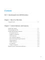
The HP Apollo 9000 Series 400 HP-UX Owner’s Guide describes how to use your
Series 400 workstation with the HP-UX operating system.
We’ve organized this manual as follows:
Chapter 1
Introduces this guide.
Chapter 2
Describes the Series 400 workstation’s controls,
connectors, and indicators.
Chapter 3
Describes how to start up your Series 400 workstation.
Chapter 4
Introduces you to the concept of HP-UX partitions and
filesets.
Chapter 5
Shows you how to get started with HP-UX.
Chapter 6
Shows you how to operate within HP-UX and its file
system.
Chapter 7
Shows you how to use vi.
Chapter 8
Shows you how to perform some HP-UX
administrative tasks.
Chapter 9
Shows you what to do if your workstation crashes.
xi
Preface
Audience
This guide is intended for use by individuals who may be unfamiliar with either
hardware or software aspects of the HP Apollo 9000 Series 400 workstation. After
reading this guide, readers will understand the basic hardware and software associated
with the HP Apollo 9000 Series 400 workstation to either embark on their own or
refer to more detailed manuals.
Related Manuals
•
•
•
•
•
•
•
•
•
•
HP Apollo Series 400 Model 400dl, 400t, 425t Installation Guide (A1630-90001)
HP Apollo Series 400 Model 400s and 433s Installation Guide (A1421-90001)
Installing HP-UX (98594-90013)
A Beginner’s Guide to HP-UX (98594-90006)
A Beginner’s Guide to Using Shells (98594-90008)
A Beginner’s Guide to Text Editing (98594-90010)
HP-UX System Administration Tasks (98594-90061)
HP-UX System Administration Concepts (98594-90062)
The Visual Users Environment User’s Guide (B1171-90002)
Installing Peripherals Guide (B1862-90007)
Problems, Questions, and Suggestions
If you have questions or problems with our hardware, software, or documentation,
please contact either your HP Response Center or your local HP representative.
Alternatively, you may use the Reader’s Response Form at the back of this manual to
submit comments about documentation.
xii
Preface
Documentation Conventions
Unless otherwise noted in the text, this manual uses the following symbolic conventions.
literal values
Bold words or characters in formats and command descriptions represent commands or keywords that you must use
literally. Pathnames are also in bold. Bold words in text
indicate the first use of a new term.
user-supplied values
Italic words or characters in formats and command descriptions represent values that you must supply.
sample user input
In samples, information that the user enters appears in
color.
[
]
Square brackets enclose optional items in formats and
command descriptions.
{
}
Braces enclose a list from which you must choose an item
in formats and command descriptions.
|
<
A vertical bar separates items in a list of choices.
>
Angle brackets enclose the name of a key on the keyboard.
CTRL/Z
The notation CTRL/ followed by the name of a key
indicates a control character sequence. Hold down
< CTRL > while you press the key.
...
Horizontal ellipsis points indicate that you can repeat the
preceding item one or more times.
.
.
.
Vertical ellipsis points mean that irrelevant parts of a figure
or example have been omitted.
This symbol indicates the end of a chapter or part of a
manual.
xiii
Contents
Part 1 – Introducing the Series 400 Workstations
Chapter 1 How to Use This Guide
Using this Guide . . . . . . . . . . . . . . . . . . . . . . . . . . . . . . . . . . . . . . . . . . . . . . 1-2
Chapter 2 Controls, Indicators, and Connectors
System Unit Controls . . . . . . . . . . . . . . . . . . . . . . . . . . . . . . . . . . . . . . . . . . 2-2
Understanding the LEDs . . . . . . . . . . . . . . . . . . . . . . . . . . . . . . . . . . . . . . . . 2-4
System Unit Rear Panel Connectors . . . . . . . . . . . . . . . . . . . . . . . . . . . . . . 2-6
Keyboard Connectors . . . . . . . . . . . . . . . . . . . . . . . . . . . . . . . . . . . . . . . 2-12
Parallel I/O Connectors . . . . . . . . . . . . . . . . . . . . . . . . . . . . . . . . . . . . . 2-13
SCSI Connectors . . . . . . . . . . . . . . . . . . . . . . . . . . . . . . . . . . . . . . . . . . . 2-14
802.3 Network Connectors . . . . . . . . . . . . . . . . . . . . . . . . . . . . . . . . . . . 2-18
RS-232 Serial Input/Output Connectors . . . . . . . . . . . . . . . . . . . . . . . . . 2-20
HP-IB Connector . . . . . . . . . . . . . . . . . . . . . . . . . . . . . . . . . . . . . . . . . . . 2-22
SPKR Connectors . . . . . . . . . . . . . . . . . . . . . . . . . . . . . . . . . . . . . . . . . . 2-24
ac Connectors . . . . . . . . . . . . . . . . . . . . . . . . . . . . . . . . . . . . . . . . . . . . . 2-25
Graphics Connectors . . . . . . . . . . . . . . . . . . . . . . . . . . . . . . . . . . . . . . . . 2-27
Monitor Controls, Connectors and Indicators . . . . . . . . . . . . . . . . . . . . . . . . 2-29
xv
Contents
Part 2 – Getting Started
Chapter 3 Booting Your Series 400 Workstation
Booting . . . . . . . . . . . . . . . . . . . . . . . . . . . . . . . . . . . . . . . . . . . . . . . . . . . . .
Configuring the Boot ROM . . . . . . . . . . . . . . . . . . . . . . . . . . . . . . . . . . . . .
Boot Mode Selection . . . . . . . . . . . . . . . . . . . . . . . . . . . . . . . . . . . . . . .
I/O Interfaces . . . . . . . . . . . . . . . . . . . . . . . . . . . . . . . . . . . . . . . . . . . . .
Auto System Select Mode . . . . . . . . . . . . . . . . . . . . . . . . . . . . . . . . . . .
Scan for System . . . . . . . . . . . . . . . . . . . . . . . . . . . . . . . . . . . . . . . . . . .
Selected System . . . . . . . . . . . . . . . . . . . . . . . . . . . . . . . . . . . . . . . . . . .
3-2
3-4
3-4
3-8
3-10
3-12
3-14
Chapter 4 Partitions and Filesets
Partitions . . . . . . . . . . . . . . . . . . . . . . . . . . . . . . . . . . . . . . . . . . . . . . . . . . . . 4-1
Filesets . . . . . . . . . . . . . . . . . . . . . . . . . . . . . . . . . . . . . . . . . . . . . . . . . . . . . 4-3
Installing HP-UX . . . . . . . . . . . . . . . . . . . . . . . . . . . . . . . . . . . . . . . . . . . . . 4-3
Chapter 5 Getting Started with HP-UX
Logging In . . . . . . . . . . . . . . . . . . . . . . . . . . . . . . . . . . . . . . . . . . . . . . . . . . .
Login . . . . . . . . . . . . . . . . . . . . . . . . . . . . . . . . . . . . . . . . . . . . . . . . . . . .
Password . . . . . . . . . . . . . . . . . . . . . . . . . . . . . . . . . . . . . . . . . . . . . . . . .
TERM = (hp) . . . . . . . . . . . . . . . . . . . . . . . . . . . . . . . . . . . . . . . . . . . . .
Logging Out . . . . . . . . . . . . . . . . . . . . . . . . . . . . . . . . . . . . . . . . . . . . . . . . .
xvi
5-2
5-4
5-6
5-8
5-12
Contents
Chapter 6 Introducing the File System
How to Read and Use HP-UX Reference Manuals . . . . . . . . . . . . . . . . . . .
Manual Organization . . . . . . . . . . . . . . . . . . . . . . . . . . . . . . . . . . . . . . .
Interpreting a Manual Page . . . . . . . . . . . . . . . . . . . . . . . . . . . . . . . . . .
Pathnames . . . . . . . . . . . . . . . . . . . . . . . . . . . . . . . . . . . . . . . . . . . . . . . .
Creating New Directories . . . . . . . . . . . . . . . . . . . . . . . . . . . . . . . . . . . .
Changing Current Directories . . . . . . . . . . . . . . . . . . . . . . . . . . . . . . . .
Listing the Files in a Directory . . . . . . . . . . . . . . . . . . . . . . . . . . . . . . . .
Viewing a File . . . . . . . . . . . . . . . . . . . . . . . . . . . . . . . . . . . . . . . . . . . . .
Removing Files and Directories . . . . . . . . . . . . . . . . . . . . . . . . . . . . . . .
Copying and Renaming Files . . . . . . . . . . . . . . . . . . . . . . . . . . . . . . . . .
Printing Files . . . . . . . . . . . . . . . . . . . . . . . . . . . . . . . . . . . . . . . . . . . . . .
6-2
6-2
6-4
6-6
6-8
6-10
6-12
6-13
6-14
6-16
6-18
Chapter 7 Using a Text Editor
Starting vi . . . . . . . . . . . . . . . . . . . . . . . . . . . . . . . . . . . . . . . . . . . . . . . . . . . 7-2
Selecting Editing Functions . . . . . . . . . . . . . . . . . . . . . . . . . . . . . . . . . . . . . 7-4
Performing Editing Functions . . . . . . . . . . . . . . . . . . . . . . . . . . . . . . . . . . . . 7-6
Positioning the Cursor . . . . . . . . . . . . . . . . . . . . . . . . . . . . . . . . . . . . . . . . . . 7-8
Leaving Text Mode . . . . . . . . . . . . . . . . . . . . . . . . . . . . . . . . . . . . . . . . . . . . 7-10
Saving Your Work . . . . . . . . . . . . . . . . . . . . . . . . . . . . . . . . . . . . . . . . . . . . . 7-11
Leaving vi . . . . . . . . . . . . . . . . . . . . . . . . . . . . . . . . . . . . . . . . . . . . . . . . . . . 7-12
xvii
Contents
Part 3 — Administrative Tasks
Chapter 8
Administrative Tasks
Creating New User Accounts . . . . . . . . . . . . . . . . . . . . . . . . . . . . . . . . . . . . 8-1
Creating, Changing, or Setting Your Password . . . . . . . . . . . . . . . . . . . . . . 8-2
Creating A New Password . . . . . . . . . . . . . . . . . . . . . . . . . . . . . . . . . . . 8-2
Initial Password . . . . . . . . . . . . . . . . . . . . . . . . . . . . . . . . . . . . . . . . . . . 8-2
Changing or Setting Your New Password . . . . . . . . . . . . . . . . . . . . . . . 8-2
Modifying Your Environment . . . . . . . . . . . . . . . . . . . . . . . . . . . . . . . . . . . . 8-4
Shutting Down . . . . . . . . . . . . . . . . . . . . . . . . . . . . . . . . . . . . . . . . . . . . . . . . 8-4
Troubleshooting HP-UX . . . . . . . . . . . . . . . . . . . . . . . . . . . . . . . . . . . . . . . . 8-11
Chapter 9
Recovering from a System Panic
Panics . . . . . . . . . . . . . . . . . . . . . . . . . . . . . . . . . . . . . . . . . . . . . . . . . . . . . . . 9-1
Record the Panic Message . . . . . . . . . . . . . . . . . . . . . . . . . . . . . . . . . . . 9-2
Categorize the Panic . . . . . . . . . . . . . . . . . . . . . . . . . . . . . . . . . . . . . . . . 9-2
Corrective Process . . . . . . . . . . . . . . . . . . . . . . . . . . . . . . . . . . . . . . . . . . 9-2
Minimizing the Effects of a Panic . . . . . . . . . . . . . . . . . . . . . . . . . . . . . . . . . 9-4
Schedule . . . . . . . . . . . . . . . . . . . . . . . . . . . . . . . . . . . . . . . . . . . . . . . . . 9-4
Media . . . . . . . . . . . . . . . . . . . . . . . . . . . . . . . . . . . . . . . . . . . . . . . . . . . . 9-4
Commands . . . . . . . . . . . . . . . . . . . . . . . . . . . . . . . . . . . . . . . . . . . . . . . . 9-5
Glossary
Index
xviii
Contents
Figures
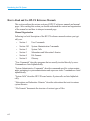
1-1 HP-UX Documentation for
HP Apollo 9000 Series 400 Workstations . . . . . . . . . . . . . . . . . . . . . . 1-3
2-1 System Unit Controls . . . . . . . . . . . . . . . . . . . . . . . . . . . . . . . . . . . . . 2-3
2-2 Front Panel LEDs . . . . . . . . . . . . . . . . . . . . . . . . . . . . . . . . . . . . . . . . 2-5
2-3 Model 400dl, 400t, and 425t Workstations
Rear Panel Connectors . . . . . . . . . . . . . . . . . . . . . . . . . . . . . . . . . . . . 2-7
2-4 Model 400s and 433s Workstations Rear Panel Connectors
(4-Slot ISA Card Cage) . . . . . . . . . . . . . . . . . . . . . . . . . . . . . . . . . . . . 2-9
2-5 Model 400s and 433s Workstations Rear Panel Connectors
(3-Slot DIO II Card Cage) . . . . . . . . . . . . . . . . . . . . . . . . . . . . . . . . . 2-11
2-6 HP-HIL Keyboard Connector . . . . . . . . . . . . . . . . . . . . . . . . . . . . . . 2-12
2-7 Parallel I/O Connector . . . . . . . . . . . . . . . . . . . . . . . . . . . . . . . . . . . . 2-13
2-8 SCSI Connector . . . . . . . . . . . . . . . . . . . . . . . . . . . . . . . . . . . . . . . . . 2-15
2-9 802.3 Network Connectors . . . . . . . . . . . . . . . . . . . . . . . . . . . . . . . . . 2-19
2-10 RS-232 Connectors . . . . . . . . . . . . . . . . . . . . . . . . . . . . . . . . . . . . . . . 2-21
2-11 HP-IB Connectors . . . . . . . . . . . . . . . . . . . . . . . . . . . . . . . . . . . . . . . . 2-23
2-12 SPKR Connectors . . . . . . . . . . . . . . . . . . . . . . . . . . . . . . . . . . . . . . . . 2-24
2-13 ac Connectors . . . . . . . . . . . . . . . . . . . . . . . . . . . . . . . . . . . . . . . . . . . 2-26
2-14 Graphics Connectors . . . . . . . . . . . . . . . . . . . . . . . . . . . . . . . . . . . . . . 2-28
2-15 19-Inch Color Monitor Controls, Indicators,
and Connectors . . . . . . . . . . . . . . . . . . . . . . . . . . . . . . . . . . . . . . . . . . . 2-30
2-16 19-Inch Monochrome Monitor Controls, Indicators, and Connectors 2-31
2-17 16-Inch Color Monitor Controls, Indicators, and Connectors . . . . . . 2-32
3-1
3-2
3-3
3-4
Configuration Control Menu . . . . . . . . . . . . . . . . . . . . . . . . . . . . . . . .
Boot Mode Selection Menu . . . . . . . . . . . . . . . . . . . . . . . . . . . . . . . .
Select Temporary or Permanent Boot Mode . . . . . . . . . . . . . . . . . . .
Auto System Select Menu . . . . . . . . . . . . . . . . . . . . . . . . . . . . . . . . .
3-5
3-5
3-7
3-11
xix
Contents
4-1 Partitions . . . . . . . . . . . . . . . . . . . . . . . . . . . . . . . . . . . . . . . . . . . . . . . 4-2
xx
5-1
5-2
5-3
5-4
5-5
5-6
Login Screen . . . . . . . . . . . . . . . . . . . . . . . . . . . . . . . . . . . . . . . . . . . .
Enter Your Username . . . . . . . . . . . . . . . . . . . . . . . . . . . . . . . . . . . . .
Copyright Screen . . . . . . . . . . . . . . . . . . . . . . . . . . . . . . . . . . . . . . . .
Select a Terminal Type . . . . . . . . . . . . . . . . . . . . . . . . . . . . . . . . . . . .
Logging Out . . . . . . . . . . . . . . . . . . . . . . . . . . . . . . . . . . . . . . . . . . . .
Log Out Screen . . . . . . . . . . . . . . . . . . . . . . . . . . . . . . . . . . . . . . . . .
5-3
5-5
5-7
5-11
5-13
5-13
6-1
6-2
6-3
6-4
6-5
6-6
6-7
HP-UX Reference Manuals . . . . . . . . . . . . . . . . . . . . . . . . . . . . . . . .
Pathnames . . . . . . . . . . . . . . . . . . . . . . . . . . . . . . . . . . . . . . . . . . . . . .
How to Create New Directories . . . . . . . . . . . . . . . . . . . . . . . . . . . . .
How to Change Directories . . . . . . . . . . . . . . . . . . . . . . . . . . . . . . . .
Removing Files and Directories . . . . . . . . . . . . . . . . . . . . . . . . . . . . .
Copying and Renaming Files . . . . . . . . . . . . . . . . . . . . . . . . . . . . . . .
Cancelling a Printer Request . . . . . . . . . . . . . . . . . . . . . . . . . . . . . . .
6-3
6-7
6-9
6-11
6-15
6-17
6-19
7-1
7-2
7-3
7-4
7-5
Displaying an Existing File . . . . . . . . . . . . . . . . . . . . . . . . . . . . . . . . .
Creating a New File . . . . . . . . . . . . . . . . . . . . . . . . . . . . . . . . . . . . . . .
Operating in vi . . . . . . . . . . . . . . . . . . . . . . . . . . . . . . . . . . . . . . . . . .
Positioning the Cursor . . . . . . . . . . . . . . . . . . . . . . . . . . . . . . . . . . . . .
Leaving Text Mode . . . . . . . . . . . . . . . . . . . . . . . . . . . . . . . . . . . . . . .
7-3
7-3
7-7
7-9
7-10
8-1
8-2
8-3
8-4
8-5
8-6
8-7
8-8
Changing Your Password . . . . . . . . . . . . . . . . . . . . . . . . . . . . . . . . . .
Creating a New Password . . . . . . . . . . . . . . . . . . . . . . . . . . . . . . . . . .
Shut Down . . . . . . . . . . . . . . . . . . . . . . . . . . . . . . . . . . . . . . . . . . . . . .
Change to Root Directory . . . . . . . . . . . . . . . . . . . . . . . . . . . . . . . . . .
Enter the shutdown Command . . . . . . . . . . . . . . . . . . . . . . . . . . . . . .
Shutdown Set for 30 Seconds . . . . . . . . . . . . . . . . . . . . . . . . . . . . . . .
Continuing with the Shutdown . . . . . . . . . . . . . . . . . . . . . . . . . . . . . .
System Halted Screen . . . . . . . . . . . . . . . . . . . . . . . . . . . . . . . . . . . . .
8-3
8-3
8-5
8-7
8-7
8-8
8-9
8-10
Contents
Tables
2-1 SCSI Cables for Series 400 Workstations
and Their SCSI Peripheral . . . . . . . . . . . . . . . . . . . . . . . . . . . . . . . . . . 2-16
2-2 Series 400 SCSI Device Cabling Configurations . . . . . . . . . . . . . . . . 2-17
3-1 Power up Screens for HP-UX . . . . . . . . . . . . . . . . . . . . . . . . . . . . . . . 3-3
3-2 Built-in Interface Default Configurations . . . . . . . . . . . . . . . . . . . . . . 3-9
3-3 Mass Storage Search Priorities . . . . . . . . . . . . . . . . . . . . . . . . . . . . . . 3-13
5-1 Select a Terminal Type . . . . . . . . . . . . . . . . . . . . . . . . . . . . . . . . . . . . 5-9
7-1 Basic Editing Functions . . . . . . . . . . . . . . . . . . . . . . . . . . . . . . . . . . . 7-5
9-1 Correcting a Panic . . . . . . . . . . . . . . . . . . . . . . . . . . . . . . . . . . . . . . . . 9-3
xxi
Part 1 — Introducing
the Series 400
Workstation
Chapter 1
How to Use This Guide
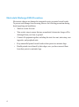
This chapter tells you how to use this owner’s guide. This guide provides directions
for running HP-UX on the HP Apollo 9000 Series 400 workstation. This chapter
describes:
•
Which chapters you need to read to use your workstation
•
The manuals shipped with your workstation
1-1
How To Use This Guide
Using This Guide
This guide tells how to start up your system. Use this guide after you have installed
your system, using the HP Model 400s and 433s Installation Guide or the HP Apollo
Model 400t, 400dl, 425t Installation Guide.
This guide is divided into three parts.
Part 1 contains this chapter and general information about your HP Apollo 9000
Series 400 workstation.
Part 2 contains instructions for getting started with HP-UX on your HP Apollo 9000
Series 400 workstation.
Part 3 contains information about administrative tasks related to HP-UX and your
HP Apollo 9000 Series 400 workstation.
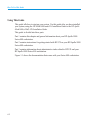
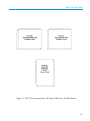
Figure 1-1 shows the documentation that comes with your Series 400 workstation.
1-2
How To Use This Guide
Figure 1-1. HP-UX Documentation for HP Apollo 9000 Series 400 Workstations
1-3
Chapter 2
Controls, Indicators, and Connectors
This chapter introduces the Series 400 workstation. It describes the following:
•
System unit controls
•
System unit LED indicators
•
System unit connectors
•
Monitor controls
2-1
Controls, Indicators, and Connectors
System Unit Controls
Before powering on your system, you should become familiar with the system unit
controls.
Figure 2-1 shows the Power, Reset, and Service mode switches. Use the Power
switch to power the system unit on and off. The Power switch also controls power
to the monitor ac connector when connected to the Model 400dl, 400t, or 425t
workstations.
Do not use excessive force when you press the Reset or Service mode switches; you
need only press them gently.
Press the Reset switch to restart the workstation (reset the operating system).
You use the Service switch when you boot the workstation. Refer to Chapter 3 for
more information about the Service switch.
2-2
Controls, Indicators, and Connectors
Figure 2-1. System Unit Controls
2-3
Controls, Indicators, and Connectors
Understanding the LEDs
There are ten LEDs located on the front of the system unit. The Series 400 workstation has 8 amber LEDs and 2 green LEDs. The green power LED of the Model
400t, 425t, and 400dl is not located with the remaining 9 LEDs. It is located near the
power switch. The green power switch of the Models 400s and 433s is the top LED
in the pattern of 10 LEDs. It is lighted when the system is powered on.
HP-UX only uses the power LED. The remaining LEDs are used by Domain/OS for
troubleshooting and indicating various operating system and network activities.
Figure 2-2 shows the workstations’ LEDs.
2-4
Controls, Indicators, and Connectors
Figure 2-2. Front Panel LEDs
2-5
Controls, Indicators, and Connectors
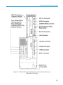
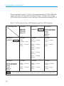
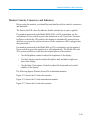
System Unit Rear Panel Connectors
This section describes the connectors on the system unit’s rear panel. They are:
•
Graphics Board Connector
•
SCSI Connector (not available on Model 400dl)
•
Parallel I/O Connector (not available on Model 400dl)
•
DOMAIN Keyboard Connector (not used with workstations running HP-UX)
•
Monitor ac Connector (available only on Models 400dl, 400t, and 425t)
•
Token Ring Network Connector for Apollo Token Ring Network or IBM
802.5 Token Ring Network (not available on Model 400dl, and not used with
workstations running HP-UX)
•
Audio Connector (not used with workstations running Domain/OS)
•
RS-232 Connector
•
802.3 Network Connectors (ThinLAN and AUI)
•
System ac Connector
•
HP-IB Connector (not available on Model 400dl, and not used with
workstations running Domain/OS)
•
HP-HIL Connector (not used with workstations running Domain/OS)
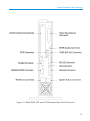
See Figure 2-3 for the locations of these connectors on the rear panel of the Model
400dl, 400t, and 425t workstations.
2-6
Controls, Indicators, and Connectors
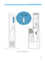
Figure 2-3. Model 400dl, 400t, and 425t Workstations Rear Panel Connectors
2-7
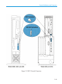
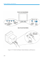
Controls, Indicators, and Connectors
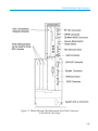
There are two different card cages available for the model 400s and 433s workstations. One card cage contains four optional slots, which can be used for four ISA
boards (including Token Ring Network boards). The other card cage contains three
optional slots, which can be used for three DIO II boards.
Figure 2-4 shows the rear panel connectors on the Model 400s and 433s workstations with the four optional ISA slots.
2-8
Controls, Indicators, and Connectors
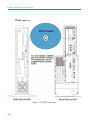
Figure 2-4. Model 400s and 433s Workstations Rear Panel Connectors
(4-Slot ISA Card Cage)
2-9
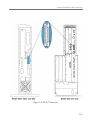
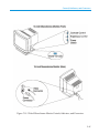
Controls, Indicators, and Connectors
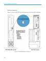
See figure 2-5 for the locations of the rear panel connectors on the Model 400s and
433s workstations with the three optional DIO II boards.
2-10
Controls, Indicators, and Connectors
Figure 2-5. Model 400s and 433s Workstations Rear Panel Connectors
(3-Slot DIO II Card Cage)
2-11
Controls, Indicators, and Connectors
Keyboard Connectors
Figure 2-6 shows the HP-HIL keyboard connectors on the Series 400 workstations.
Figure 2-6. HP-HIL Keyboard Connector
2-12
Controls, Indicators, and Connectors
Parallel I/O Connectors
Figure 2-7 shows the parallel I/O connectors on the Series 400 workstations.
Figure 2-7. Parallel I/O Connector
2-13
Controls, Indicators, and Connectors
SCSI Connectors
Figure 2-8 shows the SCSI connector on the Series 400 workstations.
NOTICE:
2-14
HP Apollo provides maintenance and support for SCSI devices that
have been qualified and sold by HP Apollo. HP Apollo does not
provide maintenance for SCSI devices not sold by HP Apollo. For
a list of SCSI devices that are sold by HP Apollo, contact your sales
representative.
Controls, Indicators, and Connectors
Figure 2-8. SCSI Connector
2-15
Controls, Indicators, and Connectors
Keep in mind that 6 meters (19.6 feet) is the maximum length of SCSI cabling that
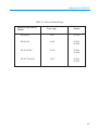
can be used with your Series 400 workstation. Table 2-1 is a shows the external
SCSI cables that are available for use with Series 400 workstations running HP-UX.
Table 2-1. SCSI Cables for Series 400 Workstations and Their SCSI Peripherals
Connecting From:
Series 400:
SCSI Device:
SCSI Device:
To:
Model 400t
Model 425t
Model 400s
Model 433s
AADDESTC See Note 1
SCSI Device:
Use Cable:
Use Cable:
C2212A (with options)
C2213A (with options)
C1700A
C1701A
7980S (xc)
C1512A
Use Cable:
AADDESTC See Note 1
K2288 –
0.9 meters (3 feet)
K2207 – 0.4 meters
(1.3 feet)
K2284 – 0.9 meters
(3 feet)
K2287 – 1.5 meters
(5 feet)
K2208 – 0.9 meters
(3 feet)
K2283 – 1.5 meter
(5 feet)
K2209 – 1.5 meters
(5 feet)
K2210 – 2.6 meters
(8.5 feet)
K2211 – 3.0 meters
(10 feet)
SCSI Device:
Use Cable:
Use Cable:
Use Cable:
C2212A (with options)
C2213A (with options)
C1700A
C1701A
7980S (xc)
C1512A
K2286 – 0.9 meters
(3 feet)
K2284 – 0.9 meters
(3 feet)
92222A – 0.5 meters
(1.6 feet)
K2285 – 1.5 meters
(5 feet)
K2283 – 1.5 meters
(5 feet)
92222B – 1 meter
(3.2 feet)
Note 1
2-16
Refer to the HP Apollo Products Price Guide for the specific Country Kit code number suffix.
Controls, Indicators, and Connectors
With the information from Table 2-1 use Table 2-2 to determine the total SCSI
cabling used for your workstation and its SCSI peripheral storage devices.
Table 2-2. Series 400 SCSI Device Cabling Configurations
SCSI Device Drives
Model 400t and 425t — all internal SCSI drives (if present)
Cable Lengths
Internal
meters (feet)
0.6 (2)
Model 400s and 433s — all internal SCSI drives (if present)
1.6 (5.5)
AADDESTC
See Note 1 and Note 2
0.6 (2)
________
C1700A
See Note 3
0.6 (2)
________
C1701A
See Note 3
0.15 (0.6)
________
C1512A
See Note 3
0.9 (3)
________
7980S (XC)
See Note 3
0.0 (0.0)
________
C2212A
See Note 3
0.9 (3)
________
C2213A
See Note 3
0.9 (3)
________
Internal + External not to exceed
Total of 6 meters (19.6 feet)
Note
1
2
3
Subtotals:
__________
External
meters (feet)
N/A
N/A
+
________
Total =
Meaning
Refer to the HP Apollo Products Price Guide for the specific Country Kit code number suffix.
Ships with one external cable K2209 (1.5 meters – 5 feet)
Ships without external cable. Cable must be ordered as separate item.
2-17
Controls, Indicators, and Connectors
802.3 Network Connectors
Figure 2-9 shows the LAN and AUI LAN connectors for the 802.3 (ETHERNET)
network on the Series 400 workstations. Which connector you use depends on the
type of cabling used at your location.
2-18
Controls, Indicators, and Connectors
Figure 2-9. 802.3 Network Connectors
2-19
Controls, Indicators, and Connectors
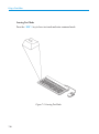
RS-232 Serial Input/Output Connectors
You can attach a variety of peripheral devices to the RS-232 port on the workstation. These peripheral devices include printers, plotters, modems, and scanners.
Consult the documentation that accompanies each peripheral device for specific
information concerning its use.
2-20
Controls, Indicators, and Connectors
Figure 2-10. RS-232 Connectors
2-21
Controls, Indicators, and Connectors
HP-IB Connector
Figure 2-11 shows the HP-IB connector on Series 400 workstations. HP-IB
(IEEE-488) supports a variety of devices sold by HP and others including the following:
•
•
•
•
2-22
Printers
Plotters
Mass storage
Instrumentation
Controls, Indicators, and Connectors
Figure 2-11. HP-IB Connectors
2-23
Controls, Indicators, and Connectors
SPKR Connectors
Figure 2-12. SPKR Connectors
2-24
Controls, Indicators, and Connectors
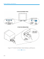
ac Connectors
Figure 2-13 shows the ac connectors on Series 400 workstations.
There is no monitor ac connector on the Model 400s or 433s workstation. Monitors
used with the Model 400s or 433s workstation have their own connection to the ac
power source.
2-25
Controls, Indicators, and Connectors
Figure 2-13. ac Connectors
2-26
Controls, Indicators, and Connectors
Graphics Connectors
Figure 2-14 shows the graphics connectors on Series 400 workstations
2-27
Controls, Indicators, and Connectors
Figure 2-14. Graphics Connectors
2-28
Controls, Indicators, and Connectors
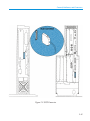
Monitor Controls, Connectors, and Indicators
Before using the monitor, you should become familiar with its controls, connectors,
and indicators.
The Power-On LED, when lit, indicates that the monitor has ac power applied.
For monitors connected to the Model 400dl, 400t, or 425t workstation, use the
workstation’s Power switch to power the monitor on or off. If you leave the monitor Power switch in the ON position, the monitor is automatically powered on or
off when you power the system unit on or off (the monitor ac cable is plugged into
the system unit.)
For monitors connected to the Model 400s or 433s workstation, use the monitor’s
Power switch to power the monitor on or off independently. The Model 400s and
433s system unit Power switch does not control power to the monitor.
•
Use the Brightness control to adjust the brightness of the display.
•
Use the Contrast control to adjust the light-to-dark and dark-to-light contrast of the display.
•
Use the Static Convergence Controls to adjust the horizontal and vertical
stability of the display.
The following figures illustrate Series 400 workstation monitors.
Figure 2-15 shows the 19-inch color monitor.
Figure 2-16 shows the 19-inch monochrome monitor.
Figure 2-17 shows the 16-inch color monitor.
2-29
Controls, Indicators, and Connectors
Figure 2-15. 19-Inch Color Monitor Controls, Indicators, and Connectors
2-30
Controls, Indicators, and Connectors
Figure 2-16. 19-Inch Monochrome Monitor Controls, Indicators, and Connectors
2-31
Controls, Indicators, and Connectors
Figure 2-17. 16-Inch Color Monitor Controls, Indicators, and Connectors
2-32
Part 2 — Getting Started
Chapter 3
Booting Your Series 400 Workstation
If your Series 400 workstation has a pre-installed operating system, it is already
configured to boot your operating system. If you are installing an operating system
on your Series 400 workstation or if it does not appear to be properly configured,
refer to “Booting” in this chapter.
3-1
Booting Your Series 400 Workstation
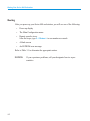
Booting
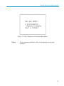
After you power up your Series 400 workstation, you will see one of the following:
•
Power-up display
•
The Main Configuration menu
•
Remote console at xxx
After the beeps, type L < Return > to use monitor as console.
•
A blank screen
•
An EEPROM error message
Refer to Table 3-1 to determine the appropriate action.
NOTICE:
3-2
If you experience problems, call your designated service representative.
Booting Your Series 400 Workstation
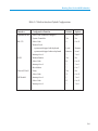
Table 3-1. Power-up Screens for HP-UX
If you see...
You need to...
Power-up display
Wait for the system to complete booting
Power-up display without the
operating system listing
Install HP-UX
Main Configuration Menu
Proceed to “Configuring the Boot ROM”
Remote console at xxx...
Type L < Return > 5 to 15 seconds after seeing
the message
A blank screen
1. Set the Service/Normal switch to Normal
2. Press < Return >
3a. If you see a blank screen:
type R < Return >
3b. If you don’t see a blank screen:
1. Type CF < Return >
2. Proceed to “Configuring the Boot ROM”
An EEPROM error message
NOTICE:
Call your designated service representative
All keyboard entries need to be uppercase.
3-3
Booting Your Series 400 Workstation
Configuring the Boot ROM
The boot ROM has three configurable areas:
•
Boot mode
•
I/O interfaces
•
Auto System Select mode
All three areas are explained in further detail in the following sections.
Boot Mode Selection
The boot mode selection defines whether an “HP-UX Compatible” or “Domain
Compatible” operating system can boot. You must set the boot mode to match the
type of operating system you are going to boot (HP-UX or Domain/OS). You set
the boot mode from the Boot Mode Selection menu.
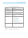
If you have not booted the system before, the Configuration Control menu will automatically appear (Figure 3-1). Select Boot Mode Selection by typing
2 < Return > and you will see the Boot Mode Selection menu (Figure 3-2).
If you have booted the system before, type C < Return > after the
HP-HIL.keyboard message appears on the screen. The Configuration Control menu
appears (Figure 3-1). Select Boot Mode Selection by typing 2 < Return >
and you will see the Boot Mode Selection menu (Figure 3-2).
If you experience problems, call your designated service representative.
3-4
Booting Your Series 400 Workstation
Figure 3-1. Configuration Control Menu
Figure 3-2. Boot Mode Selection Menu
NOTICE:
All keyboard entries need to be uppercase.
3-5
Booting Your Series 400 Workstation
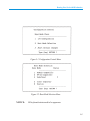
Select HP-UX Compatible by typing 2 < Return > if you will boot an
HP-UX compatible operating system.
After you select a boot mode, you see the prompt shown in Figure 3-3.
If you want to save the boot mode selection, select Permanent (P). If you save it,
the boot mode is remembered when you cycle the system’s power and you will not
have to reset the boot mode.
If you don’t want to save the boot mode selection, select Temporary (T). If you
don’t save it, the boot mode is forgotten when you power off and you must reset it
when you power on the system.
For example, if you normally boot HP-UX, you select HP-UX Compatible as the
permanent boot mode. However, if you need to boot Domain occasionally, you
temporarily select Domain Compatible. Therefore, Domain/OS will boot this time
and HP-UX Compatible operating systems can boot afterwards.
You type E < Return > to exit the menu, save your menu selections, and boot the
operating system.
3-6
Booting Your Series 400 Workstation
Figure 3-3. Select Temporary or Permanent Boot Mode
Notice:
If you experience problems, call your designated service representative.
3-7
Booting Your Series 400 Workstation
I/O Interfaces
The I/O interfaces determine the communication path between the CPU and the
I/O devices. Your Series 400 workstation already has default values set for the interfaces as shown in Table 3-2. Your Series 400 workstation will function properly
with these settings. However, you may have a special need that requires you to
change them.
If you want to change the default settings, refer to Installing Peripherals (Vols. 1 and
2).
3-8
Booting Your Series 400 Workstation
Table 3-2. Built-in Interface Default Configurations
Interface
Configuration Function
Default
Options
Optional HP-IB
Select Code (cannot be changed)
7
None
System Controller
Yes
No
Select Code
9
0 to 31
system unit shipped with keyboard
Local
Remote
system unit shipped without keyboard
Remote
Local
Interrupt Level
3
3 to 6
Modem Enable
Yes
No
Select Code
14
0 to 31
Interrupt Level
3
3 to 6
Bus Address
7
0 to 7
Parity
Yes
No
Select Code
21
0 to 31
Interrupt Level
5
3 to 6
Select Code
12
0 to 31
Interrupt Level
3
3 to 6
RS-232
Remote/Local
SCSI
Thin/AUI LAN
HP Parallel
3-9
Booting Your Series 400 Workstation
Auto System Select Mode
The auto system select mode only works if you select HP-UX Compatible for your
system’s boot mode.
The Auto System Select mode determines how an operating system is selected for
booting. You can select the auto system select mode to either scan for an operating
system to boot or boot a selected operating system. When you see the Configuration Control menu, select Auto System Selection by typing 2 < Return > and you
see the Auto System Select menu as shown in Figure 3-4.
3-10
Booting Your Series 400 Workstation
Figure 3-4. Auto System Select Menu
3-11
Booting Your Series 400 Workstation
Scan for System
The Scan for System selection searches mass storage devices for an operating system to boot. The first mass storage device found with an HP-UX Compatible operating system on it boots. Mass storage devices are searched by the priority
shown in Table 3-3.
Set the Store System Selection mode to store the boot path of the operating system
that you just selected by typing 3 < Return >, if you wish to automatically boot that
system in the future. The stored operating system is automatically booted in
all future boots, until you change your selection.
3-12
Booting Your Series 400 Workstation
Table 3-3. Mass Storage Search Priorities
Priority Level
Device
Select Code
Bus Address
Unit Number
1
SCSI
0-31
7-5
0
2
HP-IB
0-31
7-5
0
3
SRM
14
N/A
N/A
4
LAN
21
N/A
N/A
5
Bubble RAM
30
N/A
N/A
6
EEPROM
N/A
N/A
0
7
SCSI
0-31
4-0
0
8
HP-IB
0-31
4-0
0
9
SRM
Other than 14
N/A
N/A
10
LAN
Other than 21
N/A
N/A
11
Bubble RAM
Other than 30
N/A
N/A
12
EEPROM
Other than 0
N/A
0
3-13
Booting Your Series 400 Workstation
Selected System
The Selected System mode provides you with the opportunity to select a mass storage device to boot from. A list of mass storage devices appears in the upper-right
of your screen. You enter the two or three character sequence to the left of the mass
storage definition and press < Return > to select the operating system you wish to
boot. For example, type 1H < Return >.
Set the Store System Selection mode to store the boot path of the operating system
that you just selected by typing 3 < Return > , if you wish to automatically boot
that system in the future. The stored operating system is automatically booted in all
future boots, until you change your selection.
3-14
Chapter 4
Partitions and Filesets
This chapter introduces partitions and filesets, since you need to answer questions
about them while you install HP-UX.
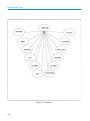
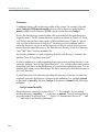
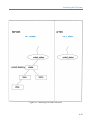
Partitions
HP-UX is divided into twelve logical areas. Each of these areas provides a task that
you may wish to perform, such as networking. These areas are called partitions. HPUX logical partitions should not be confused with the physical partitions on a disk.
Figure 4-1 shows the partitions that can be selected to create HP-UX.
4-1
Partitions and Filesets
Figure 4-1. Partitions
4-2
Partitions and Filesets
Filesets
Partitions are divided into logical areas known as filesets. Filesets are the tools
you select to perform the task. Partitions can be considered the “whats” and the
filesets the “hows.” For example, within the networking partition there are filesets,
or tools, called ARPA.38 and NFS_INCL.38 which provide ARPA and NFS functionality, respectively. Both provide networking capability; the “what.” However,
each tool provides networking differently, the “how.” These filesets contain all of
the files required to provide the ARPA and NFS functionality.
The partitions and filesets, or tasks and tools, you choose during the menu driven
installation depend on the operating system functionality you want to have.
Installing HP-UX
Install HP-UX according to the instructions in Installing HP-UX.
4-3
Chapter 5
Getting Started with HP-UX
You should have already installed your new Series 400 workstation following the
instructions in your HP Apollo Model 400t, 400dl, 425t Installation Guide or your
HP Apollo Model 400s and 433s Installation Guide and booted it following the instructions in Chapter 4.
If your Series 400 workstation has pre-installed HP-UX, it will boot a menu driven
windows environment and you should refer to chapters 2 and 3 of The Visual Users
Environment User’s Guide for information about getting started with HP-UX within the visual users environment (VUE).
This chapter tells you how to get started with HP-UX. It covers the following topics:
•
•
Logging in
Logging out
5-1
Getting Started with HP-UX
Logging In
Logging in allows you to start working with the computer; for example, you can run
an application such as a computer-aided design program. Once you log in, you
see a command line prompt which is a special symbol or word that indicates HPUX is running and waiting for your next command. You see a prompt when HPUX completes executing any command you enter. During the login sequence the
prompts will indicate what you need to enter. Respond to the prompts, as explained in the following sections, and press < Return >. After you successfully log
in, the prompt remains the same. Typical prompts include “%”, “$”, and “#”.
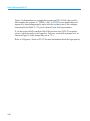
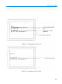
After the workstation boots, you see a screen similar to Figure 5-1 displaying a
“login:” prompt.
If you don’t see this screen, press < Return > . If you still don’t see this screen,
consult your system administrator or refer to HP-UX System Administration Concepts.
5-2
Getting Started with HP-UX
Figure 5-1. Login Screen
5-3
Getting Started with HP-UX
Login
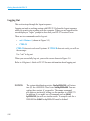
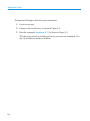
Respond to the “login:” prompt by entering your username. If you type in the username alice, you see a screen similar to Figure 5-2.
You must identify yourself to HP-UX by entering your username at the login
prompt. Ask your system administrator to assign you a username.
If you are the system administrator, you already have a username, root. But you
should also create a new user account for yourself to use when you are not doing
system administrative tasks. Refer to “Creating New User Accounts” for more information.
If you make a typing mistake, press < Return >. If the “Password:” prompt displays, then press < Return > again. The “login:” prompt will return after displaying error messages. You cannot use < Back space > to correct typing mistakes
while you log in, you may use either the “#” or “@” keys as backspace keys. Then,
re-enter your username.
5-4
Getting Started with HP-UX
Figure 5-2. Enter Your Username
5-5
Getting Started with HP-UX
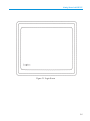
Password
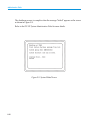
HP-UX prompts you for a password if your site requires one. Respond to the
password prompt by entering your password. If you enter the correct password,
you will see a screen similar to Figure 5-3. If this is the first time you have logged
in and you do not see a screen similar to Figure 5-3, refer to “Creating, Changing
or Setting Your Password.”
NOTICE:
Your password is not displayed on the screen in order to ensure its secrecy. If you make a typing mistake, press
< Return > and the “login:” prompt will return after displaying error messages. Now, re-enter your username.
Refer to “Creating, Changing or Setting Your Password” for more information regarding passwords.
5-6
Getting Started with HP-UX
Figure 5-3. Copyright Screen
5-7
Getting Started with HP-UX
TERM = (hp)
Respond to this prompt by entering the terminal type.
Every monitor has a terminal type by which HP-UX identifies it. The
“TERM = (hp) “ prompt appears after the “login:” prompt, or after the “Password:” prompt if you need to use a password.
See Table 5-1 to find the correct response to use for your terminal type.
Refer to “Modifying Your Environment” for information on how to configure your
environment to automatically recognize your terminal type or correct it if it becomes corrupted. The tset command will generate a new “TERM = (hp)” prompt
and you can change your terminal type for the this session of HP-UX. If you
choose to modify your environment, the change will remain from session to session; however, if you use tset, it will be lost when you log out.
5-8
Getting Started with HP-UX
Table 5-1. Select a Terminal Type
Supported Video Card or
Product
Term = (hp)
Monitor
HP A1096A
300h
98774A
HP A1416A
98550
98754A
98789A
HP 98705A/B/C
98705
98754A
98789A
HP 98735A/6A/6B
98735
98754A
98789A
5-9
Getting Started with HP-UX
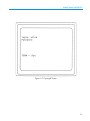
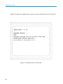
Figure 5-4 demonstrates an example that assumes an HP A1416A video card. In
this example, the response to “TERM = (hp)” is 98550. If your monitor does not
appear to be functioning properly, make sure that you have one of the configurations described in Table 5-1. If you do, then call your local representative.
If you have successfully completed all of the previous steps, HP-UX recognizes
you as a valid user and you are logged in. You see a screen with a prompt on it, as
shown in Figure 5-4 (the prompt may not be “$”).
Refer to A Beginner’s Guide to HP-UX for more information about the login process.
5-10
Getting Started with HP-UX
Figure 5-4. Select a Terminal Type
5-11
Getting Started with HP-UX
Logging Out
This section steps through the logout sequence.
Logging out ends a working session with HP-UX. Perform the logout sequence
when you want to stop working with the computer. When you are logged out the
screen displays a “login:” prompt to show that your HP-UX session is over.
There are two commands used to log out:
•
exit < Return > (shown in Figure 5-5)
•
CTRL/D
CTRL/D does not work on all systems. If CTRL/D does not work, you will see
the message:
Use “exit” to log out.
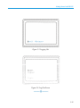
When you successfully log out, you see the screen shown in Figure 5-6.
Refer to A Beginner’s Guide to HP-UX for more information about logging out.
NOTICE:
5-12
The system identification scripts, /bin/hp9000s300, will return
true (0) for a 9000/400. There is no /bin/hp9000s400. You can
replace these scripts, if you need to. The uname command
also behaves incorrectly, telling you the machine is a 9000/375.
In addition, if you make use of commands such as #ifdef
hp9000s300 you will see similar results. To compile code for a
9000/400 the #ifdef for hp9000s300 must be defined.
Getting Started with HP-UX
Figure 5-5. Logging Out
Figure 5-6. Log Out Screen
5-13
Chapter 6
Introducing the File System
This chapter introduces files, directories, file systems, HP-UX reference manuals,
and some basic file system commands.
A file is a logical grouping of text and data, such as a memo or a program. A directory is a collection of files. How directories and files are stored and organized
defines a file system.
After reading this section you will understand the following:
•
•
•
•
•
•
•
•
•
How to read and use HP-UX reference manuals
Pathnames
Creating new directories
Changing directories
Listing the files in a directory
Viewing a file
Removing files and directories
Copying and renaming files
Printing files
6-1
Introducing the File System
How to Read and Use HP-UX Reference Manuals
This section outlines the various sections of HP-UX reference manuals and manual
pages. After reading this section you should understand the content and organization
of the manual set and how to interpret a manual page.
Manual Organization
Following is a brief description of the HP-UX reference manual sections you typically use:
•
•
•
•
•
•
Section 1
Section 1M
Section 2
Section 3
Section 4
Section 9
User Commands
System Administration Commands
System Calls
Subroutines and Subroutine Libraries
File Formats
Glossary
“User Commands” describes programs that are usually invoked directly by users.
Commands are listed alphabetically.
“System Administrative Commands” describes commands used for system maintenance pertaining to system administrator and super-user tasks. Commands are listed
alphabetically.
“System Calls” describes HP-UX kernel entries. System calls are listed alphabetically.
“Subroutines and Subroutine Libraries” describes subroutines that exist in various
system libraries.
“File Formats” documents the structure of various types of files.
6-2
Introducing the File System
Figure 6-1. HP-UX Reference Manuals
6-3
Introducing the File System
Interpreting a Manual Page
All manual entries follow an established topic format, but not all topics are included
in each entry. This section introduces the following topics:
•
•
•
•
•
NAME
SYNOPSIS
DESCRIPTION
EXAMPLES
WARNINGS
NAME gives the name(s) of the command and briefly tells you what it does.
SYNOPSIS shows you the format of what to type to execute the command.
DESCRIPTION discusses what the command does in detail and introduces the
options associated with the command.
EXAMPLES shows examples of typical command entries.
WARNINGS discusses problems that may occur using the command.
Following, is an abbreviated version of the manual page for the ls command. Refer
to ls(1) in HP-UX Reference Vol. 1 for a complete list of the options associated with
ls.
6-4
Introducing the File System
LS(1)
NAME
ls - list contents of directories
LS(1)
SYNOPSIS
ls [-abcdfgilmnopqrstuxACFHLRl][ names ]
DESCRIPTION
For each directory argument, ls lists the contents of the directory ...
Options
There are numerous options:
-a List all entries; usually entries whose names begin with a period (.) are not listed.
-b Force printing of non-graphic characters to be in the octal \ddd notation.
.
.
.
EXAMPLES
The following command prints a long listing of all the files (including the file sizes) in the
current working directory. The file most recently modified (the youngest) is listed first, then
the next youngest file, and so forth, to the oldest. Files beginning with a . are also printed.
ls -alst
WARNINGS
The option setting based on whether the output is a teletype is undesirable as ls -s is much
different than ls -s | lpr. On the other hand, not using this setting would make old shell scripts
that used ls almost inevitably fail.
6-5
Introducing the File System
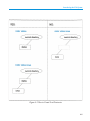
Pathnames
A pathname locates a file or directory within a file system. For example, the pathname /budget/fy1990/march/capital refers to a file or directory in the directory
march, which is in the directory fy1990, which is in the directory budget.
Root is the first directory created within a file system and all files and directories
originate from it. The file system has a tree structure as shown in Figure 6-2. Each
level below root can have many entries of files and directories; Figure 6-2 shows
only two files or directories at each level. You must cover the complete path between the directory you are at and the directory or file you wish to refer to or you
must refer to the target directory or file from the root directory. Each level between
“here” and “there” must be accounted for.
An absolute pathname is a path originating from the root directory; it answers the
question “how do I get there from root?”
A relative pathname is a path originating from your current working directory; it answers the question “how do I get there from here?” Use a relative path when you are
describing a file that is in the subdirectory of your current working directory. Use an
absolute path when you are describing a file that is more easily described in terms of
the “root” directory.
A parent directory is the directory preceding the directory of interest; its name immediately precedes the directory of interest in the pathname. For example, annual
is the parent of monthly; likewise, budget is the parent of annual in the following
pathname:
/budget/annual/monthly
Parent directories can also be referred to by “. .” . For example, if your current
working directory is monthly, “. .” is the same as annual. Current working directories can similarly be referred to as “ . ”. Figure 6-2 demonstrates the use of “. .” and
“ . ”, and relative and absolute pathnames.
6-6
Introducing the File System
Figure 6-2. Pathnames
6-7
Introducing the File System
Creating New Directories
The mkdir command creates a new directory. The parent directory should already
exist prior to executing the mkdir command. You need to have write permission on
the parent directory to use the mkdir command. If you need to change file access
permissions on the directory refer to chmod(1) in HP-UX Reference Vol. 1 for more
information about changing permissions.
Refer to mkdir(1) in HP-UX Reference Vol. 1 for more information about mkdir.
6-8
Introducing the File System
Figure 6-3. How to Create New Directories
6-9
Introducing the File System
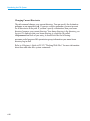
Changing Current Directories
The cd command changes your current directory. You can specify the destination
pathname as an argument to cd. If you use a relative pathname you must account
for all directories in the path. If you don’t specify a destination, then your home
directory becomes your current directory. Your home directory is the directory you
log in to. To find out what your home directory is, check the file called
/etc/password and look at your entry; it should look like the following:
username:coded password:file permission:group information:your name:home
directory:log in shell
Refer to A Beginner’s Guide to HP-UX, “Working With Files” for more information
about these and other files system commands.
6-10
Introducing the File System
Figure 6-4. How to Change Directories
6-11
Introducing the File System
Listing the Files in a Directory
The ls command lists the contents of a directory. If you don’t specify a directory
name, it lists the contents of the current directory. The output shows both files and
subdirectories intermixed in a single alphabetical list.
Refer to ls(1) in HP-UX Reference Vol. 1 for a complete list of the options for the
ls command.
To list all of the files in your current directory, enter
ls -a
6-12
Introducing the File System
Viewing a File
The more command allows you to view an existing file one screen at a time. At the
bottom of each screen more displays the percentage of the file that has been displayed. Press the spacebar to advance to the next screen. Enter q when you want to
stop reading the file.
Refer to more(1) in HP-UX Reference Vol. 1 for a complete list of the options associated with more.
For example, to see 12 more lines of the file cities, enter:
more -12 cities
6-13
Introducing the File System
Removing Files and Directories
The rm command deletes one or more entries from a directory.
The rmdir command deletes an empty directory.
Figure 6-5 demonstrates how to remove all entries in a directory and the directory itself.
If you try to delete a file or directory and get the message “Permission denied,”
you do not have the proper file access permission to delete the file or directory.
Try to change the file permissions; refer to chmod(1) in HP-UX Reference Vol. 1.
If you cannot change the permissions yourself, contact your system administrator.
Refer to rm(1) in HP-UX Reference Vol. 1 for a complete list of the options associated with rm and rmdir.
6-14
Introducing the File System
Figure 6-5. Removing Files and Directories
6-15
Introducing the File System
Copying and Renaming Files
The cp command copies an existing file into a new one. The command cp takes two
arguments, both are either filenames or pathnames to files. First, give the name of
the file you want to copy, followed by the name of the new file, cp oldfile newfile.
For example, cp games/bridge hobbies/bridge.
The mv command moves an existing file into a new one. The command mv takes
two arguments, both are either filenames or pathnames to files. First, give the name
of the file you want to move, followed by the name of the new file, mv file1 file2.
For example, mv games/bridge hobbies/bridge.
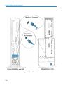
The mv and cp commands do not perform the same function. Figure 6-6 displays
the subtle but significant difference. The cp command produces a duplicate file,
maintaining the original file. The mv command also produces a duplicate file; however, it removes the original file.
If you try to copy or move a file and get the message “Permission denied,” you may
not have the correct file access permission to copy or move the file. Check the file
access permissions with the ll command. If necessary, try to change the file access
permissions; refer to chmod(1) in HP-UX Reference Vol. 1 for more information
about understanding and changing file access permissions. If you cannot change the
file access permissions yourself, contact your system administrator.
6-16
Introducing the File System
Figure 6-6. Copying and Renaming Files
6-17
Introducing the File System
Printing Files
Use the lp command to send files to a printer. After you enter the lp command, you
see a request ID displayed. You use this ID to identify your request if you need to
cancel your lp request with the cancel req_id command as shown in Figure 6-7.
Refer to lp(1) in HP-UX Reference Vol. 1 for a complete list of the options associated
with lp and cancel(1) for information on cancel.
For example, to print three copies of a file, enter:
lp -n3 filename
6-18
Introducing the File System
Figure 6-7. Cancelling a Printer Request
6-19
Chapter 7
Using a Text Editor
This chapter introduces you to a text editor called vi. Vi is an interactive text editor which enables you to view and alter text files within your file system. It allows
you to create, delete, and edit files. This section introduces the basics of operating
vi:
•
•
•
•
•
Starting vi
Selecting editing functions
Performing editing functions
Saving your work
Leaving vi
7-1
Using a Text Editor
Starting vi
Start vi by entering the command vi filename at the prompt, where filename is the
name of the file that you wish to either create, view, or alter. If a file called filename
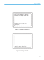
already exists, the first screen of the file will be displayed, as shown in Figure 7-1.
If the file does not exist, it is created and you see a screen like Figure 7-2.
7-2
Using a Text Editor
Figure 7-1. Displaying an Existing File
Figure 7-2. Creating a New File
7-3
Using a Text Editor
Selecting Editing Functions
You select all editing functions from command mode. Your selection determines
what you can do to the text.
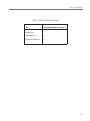
The basic editing functions you need to know to use vi are shown in Table 7-1 and
explained in “Performing Editing Functions.”
7-4
Using a Text Editor
Table 7-1. Basic Editing Functions
To...
In command mode enter...
Insert text.
i
Append text.
a
Delete a character.
x
7-5
Using a Text Editor
Performing Editing Functions
Once you start vi, you are either in command or text mode. Press the < ESC > key
to ensure that your file is in command mode so that can execute any of the following
commands:
•
The insert command:
Places your file in text mode and enters whatever you type preceding the cursor. Everything after the cursor will be moved to the right.
•
The append command:
Places your file in text mode and enters whatever you type after the cursor.
Everything after the cursor will be moved to the right.
•
The delete command:
Deletes the character that is highlighted by the cursor. This command does not
put your document in text mode.
If the command expects you to type something after entering your command to
complete the operation, you are placed in text mode; otherwise, you remain in command mode.
Each command from command mode allows you to perform only that function
within text mode. For example, if you place your file in text mode via the append
command, then you may only perform append functions. Your file must be placed
in command mode and returned text mode via the insert command before you can
insert text.
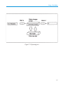
Figure 7-3 shows the overall operation of vi.
7-6
Using a Text Editor
Figure 7-3. Operating in vi
7-7
Using a Text Editor
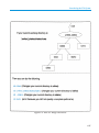
Positioning the Cursor
You may have noticed that the editing functions are performed relative to cursor position. For example, you can make text changes before, after, or at the cursor location. Many commands exist within vi that provide cursor movement and placement.
This section introduces the basic cursor commands.
Some keyboards have arrow keys labeled < Prev > and < Next >. The < Prev > key
will move the cursor to the last screen displayed on the page and < Next > moves
the cursor to the page that will be displayed next. The arrow keys move the cursor in
the indicated direction.
The most commonly used method to move the cursor is to use the h, j, k, and l keys,
since they are the home keys on the keyboard for the right hand. The keys perform
the functions shown in Figure 7-4.
7-8
Using a Text Editor
Figure 7-4. Positioning the Cursor
7-9
Using a Text Editor
Leaving Text Mode
Press the < ESC > key to leave text mode and enter command mode.
Figure 7-5. Leaving Text Mode
7-10
Using a Text Editor
Saving Your Work
You can save your work with or without quitting vi. Your document must be in command mode for you to be able to use the following commands to save your work.
Press the < ESC > key to ensure that your document is in command mode.
• ZZ
• :wq
• :w! filename
Both the ZZ and :wq commands save your file and leave vi. You execute fewer
keystrokes by using the ZZ command.
Use the :w! filename command to save your work without leaving vi. Omitting
filename from the :w! filename command saves the current file with the same name.
7-11
Using a Text Editor
Leaving vi
You can quit vi and save your work. You can also quit vi without saving your work.
Your document must be in command mode for you to be able to use the following
commands to leave vi. Press the < ESC > key to ensure that your document is in
command mode.
• ZZ
• :wq
• :q!
Both the ZZ and :wq commands save your file and leave vi. You execute fewer
keystrokes by using the ZZ command.
The q! command causes your document to leave vi without saving your changes.
Refer to A Beginner’s Guide to Text Editing for more detailed information about vi.
7-12
Part 3 — Administrative Tasks
Chapter 8
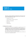
Administrative Tasks
This chapter is primarily intended for system administrators, but experienced users
who have root privileges may also find this information useful. This chapter introduces the following administrative tasks:
•
Creating new user accounts
•
Creating, changing, or setting new passwords
•
Modifying your environment
•
Shutting down
•
Troubleshooting
Creating New User Accounts
You can create new user accounts via command line or menu driven processes. The
command line process requires a solid understanding of HP-UX and can be overwhelming for a new user. The fast and easy process is to use the System Administration Manager (SAM) to create new user accounts. SAM is a menu-driven process
that is easier to use than creating a new account via the command line process. You
can use SAM to perform most system administrative tasks.
Refer to HP-UX System Administration Tasks for information on how to add new user
accounts from the command line and SAM.
8-1
Administrative Tasks
Creating, Changing, or Setting Your Password
This section shows you how to develop a valid password and how to change an
existing password or set a new password.
Creating a New Password
Passwords must meet the following criteria:
•
•
•
The password must contain 6 to 8 characters, inclusive.
At least two of the characters must be letters.
At least one character must either a numeral or special character.
The following are examples of passwords:
•
•
•
•
foo-bar
$money$
Number_9
@rophy
Initial Password
You may or may not have a password already assigned to you when you log in for
the first time. It is also possible that you will not be required to use a password.
However, if you are required to use one and it has already been assigned, you might
wish to change it. Likewise, if you are not required to use one or it has not already
been set for you, you may wish to create one.
Changing or Setting Your New Password
The passwd command changes your password. Enter the passwd command and it
will tell you what information it needs to continue. The process will be like that in
Figure 8-1 or Figure 8-2, depending on whether you are changing an existing password or creating a new password.
For further information concerning passwords, refer to A Beginner’s Guide to
HP-UX.
8-2
8-2
Administrative Tasks
Figure 8-1. Changing Your Password
Figure 8-2. Creating a New Password
8-3
Administrative Tasks
Modifying Your Environment
Your environment consists of the various options and features that affect how HPUX and your programs respond to you. As you become familiar with your environment, you may wish to customize it. A Beginner’s Guide to Using Shells provides extensive information on how to customize your environment. It explains the various
environment variables that you can modify and provides shell specific information.
Shutting Down
This section tells you how to shut down any workstation that is running HP-UX.
Generally, you shut down a workstation if you need to perform an operation that
requires the workstation to be powered off, such as adding a new graphics card, or
rebooting the system.
NOTICE:
8-4
In an HP-UX cluster, cluster clients need only log off; however, the
shutdown process works better if you turn the cluster clients off. Do
not shut down the server from a cluster client; shut down the server
directly.
Administrative Tasks
Figure 8-3. Shut down
CAUTION: Do not shut down a workstation by turning it off until the message
“halted” appears on the screen. Improperly shutting down the workstation can corrupt the filesystem.
8-5
Administrative Tasks
Perform the following to shut down your workstation:
1. Log in as root user.
2. Change to the root directory as shown in Figure 8-4.
3. Enter the command: shutdown -h XX as shown in Figure 8-5.
XX is the grace period, in seconds, until active processes are terminated. Usually, 30 seconds to a minute is sufficient.
8-6
Administrative Tasks
Figure 8-4. Change to Root Directory
Figure 8-5. Enter the shutdown Command
8-7
Administrative Tasks
Figure 8-6 shows an example where active processes will shut down in 30 seconds.
Figure 8-6. Shutdown Set for 30 Seconds
8-8
Administrative Tasks
If you answer y (yes) to the prompt in Figure 8-6, then you will see a screen similar to Figure 8-7. The login sequence starts. This login allows root to perform the
shutdown.
If you answer n (no) to the prompt in Figure 8-6, you see a prompt.
Figure 8-7. Continuing with the Shutdown
8-9
Administrative Tasks
The shutdown process is complete when the message “halted” appears on the screen
as shown in Figure 8-8.
Refer to the HP-UX System Administration Tasks for more details.
Figure 8-8. System Halted Screen
8-10
Administrative Tasks
Troubleshooting HP-UX
The Troubleshooting HP-UX Systems Error Diagnosis and Recovery provides methods for defining and isolating problems and possible solutions for the following
categories of problems:
•
•
•
•
•
•
Line printer spooling
File system
Disk space
Terminals
Boot-up
HP-UX cluster
8-11
Chapter 9
Recovering from a System Panic
Most problems are dealt with by implementing some combination of avoidance,
detection, prevention, and recovery. If you are reading this chapter, it is because any
avoidance or prevention measures have failed and a problem has been detected. This
chapter introduces recovery techniques and suggests efforts to minimize the effects
of a panic.
Panics
A panic means that the computer halted because HP-UX was asked to do something
that it did not understand. Panics are rare and are not necessarily catastrophic. The
cause may be due to something like a Local Area Network (LAN) cable being unplugged and the solution is to plug it in and reboot your system.
The basic steps to recover from a panic are:
•
•
•
Write down the panic message
Categorize the panic type
Correct the problem
9-1
Recovering from a System Panic
Record the Panic Message
Write down the message that is displayed on the screen. You may need to refer to it
later.
Categorize the Panic
A panic can be categorized into one of the following:
•
•
•
•
Hardware failure
File system problem
LAN communication problem
Other
The wording of the panic message that you wrote down directs you to the appropriate category.
Corrective Process
Once you have categorized the panic, you are ready to begin correcting the problem.
In general, correcting the problem entails performing the category specific recovery
and rebooting as shown in Table 9-1.
Once you have successfully rebooted your system you may want to perform more
frequent backups until you are confident that your system functions properly. Read
the section titled “Minimizing the Effects of a Panic” to understand how to design
and perform backups.
9-2
Recovering from a System Panic
Table 9-1. Correcting a Panic
Category
Hardware
Corrective Process
If the failure appears to be associated with the peripheral:
Check the integrity of the cable connections.
Ensure that the peripheral is online.
If the failure appears to be associated with the System Processing Unit or the above
did not correct the problem, call your designated service representative.
You may refer to Troubleshooting HP-UX Systems Error Diagnosis and Recovery for
more information.
File System
Run the file system checker (fsck) to correct the problem. Follow the directions that
fsck gives and use the -n option with any subsequent reboots required by fsck.
Refer to Troubleshooting HP-UX Systems Error Diagnosis and Recovery.
LAN
Ensure the integrity of all LAN connections; including taps in any AUI cable. Check
for proper 50 ohm terminations at both ends of the LAN.
Follow the directions that fsck gives and use the -n option with any subsequent
reboots required by fsck.
Refer to Troubleshooting HP-UX Systems Error Diagnosis and Recovery.
Other
Reboot.
Refer to Troubleshooting HP-UX Systems Error Diagnosis and Recovery.
9-3
Recovering from a System Panic
Minimizing the Effects of a Panic
Performing timely and adequate backups and implementing a good restore process
will minimize the effects of a panic. The worst scenario for recovery is reinstalling
HP-UX and restoring any lost files. Therefore, a meaningful backup would minimize the adverse affects of even the worst panic.
How frequently you backup your system and the type of backup you perform
depends on how much and what type of data you can afford to lose. You need to
consider the following topics when selecting a backup and restore process:
•
Schedules
•
Media
•
Commands
The three topics are not independent and you need to understand how each will affect your backup and restore process prior to implementing a process.
Schedule
You need to decide how often various files need to be updated. Some backups are
event driven; you update when something significant occurs, others are time driven;
you update working directories once a week or some other fixed time interval.
Media
You need to understand the size of the files on your system that you intend to
backup, since the size of the backup media must exceed the size of the file system
you wish to back up.
You should also understand the time factors associated with the backup media that
you select. For example, flexible disks are slower than optical disks. However, if
your system is quite small, using an optical disk may not make sense.
9-4
Recovering from a System Panic
Commands
Since the features of commands vary, you need to understand them in detail. Refer
to the entries for the commands in the HP-UX Reference manuals. You have the option of performing backups either manually or automatically. However, once again,
you need to understand the ramifications in detail. Automatic backups may prove to
be more restrictive.
HP-UX System Administrative Tasks is an excellent source of information about designing a backup and restore process for your system.
9-5
Glossary
application
A program used to perform a particular task, usually interactively, such as computer-aided
design, text editing, or accounting.
backup
A copy of all or part of the file system.
boot
The process of running the program in ROM that brings in the operating system and runs it.
See also boot ROM.
boot ROM
A program residing in ROM (Read-Only Memory) that executes each time the computer is
powered up. It is designed to bring the operating system into the computer and start it.
cluster
A group of workstations connected via a LAN. One computer, the cluster server, performs as
a file-system server for the cluster clients.
cluster client
A cluster node that does not have a local HP-UX file system. Its file system resides on the
cluster server.
GL-1
Glossary
cluster server
The cluster node which acts as a file system server for all the cluster nodes in an HP-UX
cluster.
command interpreter
A program which reads lines of text from standard input (typed at the keyboard or read from a
file), and interprets them as requests to execute other programs. An HP-UX command interpreter is called a shell.
cpu
The part of a computer that interprets and executes instructions.
environment
The set of defined shell variables that define the conditions under which your commands run.
These conditions can include your terminal characteristics, home directory, and default search
path.
file access permissions
Every file in the file hierarchy has a set of access permissions. These permissions are used in
determining whether a process can perform a requested operation on the file (such as opening
a file for writing).
home directory
The directory name given by the value of the shell variable HOME. This is the directory
where the user starts after logging in.
kernel
The part of the HP-UX operating system that is responsible for managing the computer’s
resources.
Local Area Network
The systems and clusters which share data, hardware, and software resources via Networking
Services software.
operating system
This is the entire HP-UX system, including the kernel and all HP-UX commands. See also
kernel.
shell
An HP-UX command interpreter. See also command interpreter.
GL-2
Glossary
shutdown
The process of taking the system from multi-user state to system administration state.
system call
Invocation of a kernel process by a user program.
working directory
This is the directory in which relative path name searches begin. It is also called the current
directory, or the current working directory.
GL-3
Index
Numbers
16-inch color monitor, controls, indicators,
and connectors, 2-32
802.3 network connectors, 2-18 through 2-19
A
absolute pathname, 6-6 through 6-7
boot mode selection, 3-4 through 3-7
booting
auto system select, 3-10 through 3-11
boot mode selection, 3-4 through 3-7
configuring the boot ROM, 3-4 through 3-14
I/O interfaces, 3-8 through 3-9
search for a system to boot, 3-12
selecting a specific system to boot, 3-14
C
ac connectors
monitor, 2-25 through 2-26
system, 2-25 through 2-26
changing current directories, 6-10 through
6-11
accounts, creating user, 8-1
changing your password, 8-2
administrative tasks
changing your password, 8-2
creating user accounts, 8-1
creating your password, 8-2
modifying your environment, 8-4
setting your password, 8-2
shutting down, 8-4
troubleshooting HP-UX, 8-12
choosing an operating system to boot, 3-10
through 3-11
appending a file, 7-4 through 7-5
how it works, 7-6
B
backups
code selection, 9-5
design of, 9-4
media selection, 9-4
more help, 9-5
schedule, 9-4
color monitor, 19-inch
connectors, 2-30
controls, 2-30
indicators, 2-30
configuring the boot ROM, 3-4 through 3-14
connectors
16-inch color monitor, 2-32
19-inch color monitor, 2-30
19-inch monochrome monitor, 2-31
graphics, 2-27—2-32
keyboard, 2-12
monitor, 2-29 through 2-32
monitor ac, 2-25 through 2-26
network, 802.3, 2-18 through 2-19
parallel I/O, 2-13
RS-232 serial I/O, 2-20 through 2-21
Index-1
Index
video, 2-27 through 2-32
controls
16-inch color monitor, 2-32
19-inch color monitor, 2-30
19-inch monochrome monitor, 2-31
monitor, 2-29 through 2-32
copying a file, 6-16 through 6-17
crash. See panic
creating
directories, 6-8 through 6-9
user accounts, 8-1
your password, 8-2
cursor, positioning the, 7-8 through 7-9
D
deleting text from a file, 7-4 through 7-5
how it works, 7-6
directories
changing current directory, 6-10 through
6-11
creating, 6-8 through 6-9
listing, 6-12
removing, 6-14 through 6-15
documentation, 1-3
F
file system commands
creating new directories, 6-8 through 6-9
listing directories, 6-12
printing a file, 6-18 through 6-19
removing directories, 6-14 through 6-15
renaming a file, 6-16 through 6-17
files
appending to, 7-6 through 7-7
Index-2
copying, 6-16 through 6-17
deleting from, 7-6 through 7-7
inserting text, 7-6 through 7-7
removing, 6-14 through 6-15
viewing, 6-13
fileset, 4-3
G
graphics connectors, 2-27 through 2-32
H
HP-UX
getting started, 5-1
installing, 4-3
structure, 4-1
troubleshooting, 8-12
I
I/O interfaces, 3-8 through 3-9
defaults, 3-3, 3-9, 3-13
indicators
16-inch color monitor, 2-32
19-inch color monitor, 2-30
19-inch monochrome monitor, 2-31
monitor, 2-29 through 2-32
inserting text into a file, 7-4 through 7-5
how it works, 7-6
K
keyboard connectors, 2-12
Index
L
LEDs
16-inch color monitor, 2-32
19-inch color monitor, 2-30
19-inch monochrome monitor, 2-31
listing directories, 6-12
logging in, 5-2 through 5-11
from a shell, 5-2 through 5-3
logging out, 5-12 through 5-13
from a shell, 5-12 through 5-13
login prompt, how to respond from a shell, 5-4
M
monitor ac connectors, 2-25 through 2-26
P
panic
cause, 9-1
corrective process, 9-2 through 9-4
minimizing the effects, 9-4
recovery steps, 9-1 types, 9-2
parallel I/O connectors, 2-13
partition, 4-1
password
changing your, 8-2
creating, 8-2
setting your, 8-2
media, backup selection, 9-4
password prompt, how to respond from shell, 5-6
Model 400s and 433s, rear panel connectors
4-slot ISA card cage, 2-9
with 3-slot DIO II card cage, 2-11
pathname, 6-6 through 6-7
absolute, 6-6 through 6-7
relative, 6-6 through 6-7
modifying your environment, 8-4
performing editing functions, 7-6 through 7-7
monitor
16-inch color, controls, indicators, and
connectors, 2-32
19-inch color
connectors, 2-30
controls, 2-30
indicators, 2-30
19-inch monochrome, controls, indicators,
and connectors, 2-31
connectors, 2-29 through 2-32
controls, 2-29 through 2-32
Brightness control, 2-29
Contrast control, 2-29
Power switch, 2-29
Power-On LED, 2-29
indicators, 2-29 through 2-32
positioning the cursor, 7-8 through 7-9
power off, how to, 8-4 through 8-11
Power-up. See booting
printing a file, 6-18 through 6-19
R
relative pathname, 6-6 through 6-7
removing
directories, 6-14 through 6-15
files, 6-14 through 6-15
renaming a file, 6-16 through 6-17
RS-232 serial I/O connectors, 2-20 through
2-21
Index-3
Index
S
troubleshooting HP-UX, 8-12
saving your work, 7-11
schedule, determing backup, 9-4
SCSI connectors, 2-14 through 2-17
selecting a boot mode, 3-4 through 3-7
selecting an operating system to boot, 3-10
through 3-11
serial I/O connectors, 2-20 through 2-21
setting your password, 8-2
shutting down, how to, 8-4 through 8-11
starting vi, 7-2 through 7-3
U
user accounts, creating, 8-1
using a text editor
leaving text mode, 7-10
leaving vi, 7-12
performing editing functions, 7-6 through
7-7
positioning the cursor, 7-8 through 7-9
saving your work, 7-11
selecting editing functions, 7-4 through 7-5
starting vi, 7-2 through 7-3
system ac connectors, 2-25 through 2-26
system unit, 2-2 through 2-3
controls, 2-2 through 2-3
illustration of LEDs, 2-5
LEDs, 2-4 through 2-5
power switch, 2-2
Reset switch, 2-2
Service mode switch, 2-2
Model 400dl, 400t, and 425t, illustration of
rear panel connectors, 2-7
power switch, controls power to the monitor,
2-2
rear panel connectors, 2-6 through 2-28
keyboard, 2-6
Model 400dl, 400t, and 425t, 2-7
monitor, 2-6
network, 2-6
T
TERM prompt, how to respond from shell
login, 5-8
Index-4
V
vi
append a file, 8-2
appending a file, 7-6 through 7-7
deleting text, 7-4 through 7-5, 7-6 through
7-7
how to start, 7-2 through 7-3
inserting text, 7-4 through 7-5, 7-6 through
7-7
viewing a file, 6-13
video connectors, 2-27 through 2-32
W
writing to a file, 7-4 through 7-5
Reader’s Response
Please take a few minutes to send us the information we need to revise and improve our manuals from
your point of view.
Document Title: HP Apollo 9000 Series 400 Workstation HP-UX Owner’s Guide
Order No.: A1630-90606
Your Name
Date
Organization
Street Address
City
State
Telephone number
(
Zip
)
When you use the HP Apollo system, what job(s) do you perform?
® Programming
® Hardware Engineering
® Other (describe)
® Application End User
® System Administration
How many years of experience do you have in using the HP Apollo system:
____________________________________________________
What programming languages do you use with the HP Apollo system?
____________________________________________________________________________________
How would you evaluate this book?
Excellent
Average
Poor
Completeness
1
2
3
4
5
Accuracy
1
2
3
4
5
Usability
1
2
3
4
5
Additional Comments:
_______________________________________________________________________
_________________________________________________________________________________________________
_________________________________________________________________________________________________
No postage necessary if mailed in the U.S.