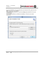
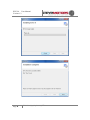
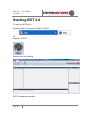
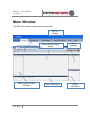
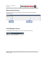
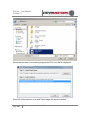
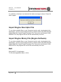
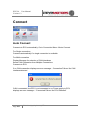
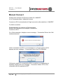
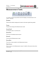
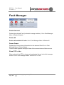
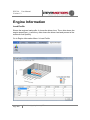
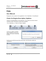
1
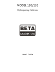
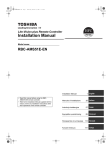
STEYR MOTORS
INNOVATION WITH LIGHTNESS
Engine Diagnostics Tool
2.0 User Manual
Version 1.3
EDT 2.0 User Manual
Version 1.3
About Manual
This manual describes the EDT 2.0 application and its ability to monitor ECU. It
provides detailed information concerning the usage of EDT 2.0 application.
This manual contains the following chapters:
Introduction
Installation
Starting EDT 2.0
Main Window
Application Menu
Connect
Measurement
Faulty Manager
Engine Information
View
Help
Revision history
Revision
No.
0.00
1.00
Revision Description
Revision Date
Document created
Document updated
1.10
1.20
Document updated
Document updated
16 January 2012
22 February
2012
13 June 2012
14 June 2012
Warning:
Failure to read and understand the information provided in this manual
may result in product failure. Please read each chapter in its entirety and
be sure you understand the information provided in the chapter and
related chapters before attempting any of the procedures or operations
given
Page 2
Z001080-0_1_02_121011_WT
EDT 2.0 User Manual
Version 1.3
Table of Contents
Prerequisites .................................................................................................................................. 5
Introduction .................................................................................................................................... 6
Installation ...................................................................................................................................... 6
Starting EDT 2.0 ........................................................................................................................... 9
Main Window ............................................................................................................................... 10
Measurement Screen ............................................................................................................. 11
Fault Manager Screen ........................................................................................................... 11
Engine Information Screen .................................................................................................... 12
Status Information Screen ..................................................................................................... 13
Application Menu ........................................................................................................................ 13
ECU Setup ............................................................................................................................... 14
ECU Software Update ............................................................................................................ 17
Import Engine Descriptor File ............................................................................................... 19
Import Engine Binary File (Engine Software) ..................................................................... 19
Exit ............................................................................................................................................ 19
Connect ........................................................................................................................................ 20
Auto Connect ........................................................................................................................... 20
Manual Connect ...................................................................................................................... 21
GPS .............................................................................................................................................. 22
Measurement............................................................................................................................... 24
Open (multiple tabs) ............................................................................................................... 24
Select Engine Signals ............................................................................................................ 24
Config Signal Parameters...................................................................................................... 27
Start Measurement ................................................................................................................. 28
Stop Measurement ................................................................................................................. 29
Resume ................................................................................................................................ 30
Pause.................................................................................................................................... 30
Axes Scroll ........................................................................................................................... 30
Page 3
Z001080-0_1_02_121011_WT
EDT 2.0 User Manual
Version 1.3
Zoom Out ............................................................................................................................. 30
Zoom In ................................................................................................................................ 30
Zoom Box ............................................................................................................................. 30
Data Cursor ......................................................................................................................... 30
Fault Manager ............................................................................................................................. 31
Delete Selected ................................................................................................................... 31
Delete All .............................................................................................................................. 31
Freeze Frame ...................................................................................................................... 31
Show DTC in Hex ............................................................................................................... 31
Engine Information ..................................................................................................................... 32
Load Profile .......................................................................................................................... 32
View .............................................................................................................................................. 33
Engine Information ............................................................................................................. 33
Fault Manager ..................................................................................................................... 33
Status Information............................................................................................................... 33
Help ............................................................................................................................................... 34
User Manual ............................................................................................................................ 34
Check for Engine Description Updates ............................................................................... 34
Page 4
Z001080-0_1_02_121011_WT
EDT 2.0 User Manual
Version 1.3
Prerequisites
Supported Operating Systems
•
•
•
Windows XP 32bit SP3
Windows Vista, 32 and 64bit
Windows 7, 32 and 64bit
• .NET Framework 4.0
Supported Hardware
• Minimum: Intel or AMD Dual-Core-Processor with 2.0 GHz or faster
• Recommended: Intel i3,i5 or i7 processor
• 2 GB RAM memory
• Free USB 2.0 Port for connecting the USB/CAN interface
Page 5
Z001080-0_1_02_121011_WT
EDT 2.0 User Manual
Version 1.3
Introduction
This software is used for diagnosis on “Steyr-Motors” Diesel engines. It supplies
data out of the engine control unit (ECU) and allows measurements and
malfunction detection.
Installation
This chapter describes the procedures involved in the installation of EDT 2.0 on a
standard workstation running under Microsoft Windows XP and 7.
The software is supplied on CD-ROM and is installed easily from within Microsoft
Windows. The installation can be terminated at any point during the installation
process.
If there is an older version of EDT 2.0 already installed, please uninstall/remove
this version first:
Page 6
Z001080-0_1_02_121011_WT
EDT 2.0 User Manual
Version 1.3
Insert the CD-ROM in the appropriate drive and select the Run option from the
Start pushbutton on the taskbar.
Click the Browse pushbutton to select the setup.exe executable file from the
CDROM drive.
Click the OK pushbutton to initiate the installation. Follow the on-screen
instructions.
Page 7
Z001080-0_1_02_121011_WT
EDT 2.0 User Manual
Version 1.3
Page 8
Z001080-0_1_02_121011_WT
EDT 2.0 User Manual
Version 1.3
Starting EDT 2.0
To open the EDT go to:
Windows Start Æ Programs Æ SMO Æ EDT2
Or
Desktop Æ EDT2
Shortcut Icon on Desktop
EDT 2.0 application window
Page 9
Z001080-0_1_02_121011_WT
EDT 2.0 User Manual
Version 1.3
Main Window
The EDT main window contains the following parts:
EDT 2.0
Ribbon
Measurement Screen
(graph)
Measurement Screen
(Numeric)
Page 10
Z001080-0_1_02_121011_WT
Status Information
Fault
Manager
Engine
Information
EDT 2.0 User Manual
Version 1.3
Measurement Screen
Measurement screen shows Graphical and Numerical values of the selected
Signals from ECU
Numeric
Graphic
Fault Manager Screen
Fault Manager Screen displays the L1 and L2 Fault values from ECU
Page 11
Z001080-0_1_02_121011_WT
EDT 2.0 User Manual
Version 1.3
Engine Information Screen
The Engine Information Section displays the following Engine
Informations:
•
•
•
•
•
•
•
•
•
•
Display Software Number
Engine Number
Engine Type
ECU Serial Number
ECU Type
Engine Timer
SR0Pos
SR18Pos
ITD0Pos
Offset SR
Page 12
Z001080-0_1_02_121011_WT
EDT 2.0 User Manual
Version 1.3
Status Information Screen
Status Information Screen shows the information of activates done on EDT 2.0
application
Application Menu
ECU Application menu consists of:
• ECU Setup
• ECU Report
• ECU Software Update
• Import Engine Descriptor File
• Import Engine Binary File
• Exit
Page 13
Z001080-0_1_02_121011_WT
EDT 2.0 User Manual
Version 1.3
ECU Setup
ECU Setup helps to modify the ECU parameters
To open ECU Setup window click Application Menu Æ ECU Setup Æ Enter
Engine number Æ Press Ok
The following window contains at least 2 parameters, according to the ECU
software there are more or less parameters:
•
•
•
•
•
•
•
•
IdleSpeed: contains the current used engine idle speed
FixedIdleSpeed1: contains the idle speed which is used, if the idle switch
is switched to position 1
FixedIdleSpeed2: contains the idle speed which is used, if the idle switch
is switched to position 2
GearParameterSet: every increase of this value will increase the idle
speed while shifting for 10%
EngineMode: choose between torque governor (select “0”) and speed
governor (select “1”)s
Gear Inversion: inverts the Gear activation
Gear Delay: Gear activation delay time in milliseconds
Gear Enable Time: activation time for gear strategy in milliseconds
Page 14
Z001080-0_1_02_121011_WT
EDT 2.0 User Manual
Version 1.3
To store the given values, press the “Store”- Button, a pop up window will show,
whether the storage was done.
To restore the default configuration, press “Restore factory default”.
Page 15
Z001080-0_1_02_121011_WT
EDT 2.0 User Manual
Version 1.3
Virgin ECU Software Update
To update a virgin / brand new ECU start EDT and click “ECU Software Update”.
A warning message appears and gives you a warning.
Page 16
Z001080-0_1_02_121011_WT
EDT 2.0 User Manual
Version 1.3
ECU Software Update
ECU Software Update helps to update the software on the ECU.
To open Software Report window click Application Menu Æ ECU Software
Update.
The Engine number is entered for validation. Press Ok button after entering the
current engine number.
Select the ECU software file using the Browse button.
Page 17
Z001080-0_1_02_121011_WT
EDT 2.0 User Manual
Version 1.3
Select the interface to be used to program the ECU from the list displayed.
Press Ok. After selection of a valid Flash image file and an interface.
Page 18
Z001080-0_1_02_121011_WT
EDT 2.0 User Manual
Version 1.3
If a valid file or interface is not selected the below message is shown. Press Ok
and try again.
Import Engine Descriptor File
To use other available files on your Computer (sent by mail, downloaded at the
homepage), you can use the import function to import a file to the SMO program
folder. Press the “Import Engine Descriptor File” menu item and choose a valid
SMOEDF file, the program will use this file automatically next time.
Import Engine Binary File (Engine Software)
To use other available files on your Computer (sent by mail, downloaded at the
homepage), you can use the import function to import a file to the SMO program
folder. Press the “Import Engine Descriptor File” menu item and choose a valid
SMOCRP file, the program will use this file automatically next time.
Exit
Exits the EDT 2.0 application
To Exit click Application Menu Æ Exit.
Page 19
Z001080-0_1_02_121011_WT
EDT 2.0 User Manual
Version 1.3
Connect
Auto Connect
Connects to ECU automatically. Go to Connection Menu ÆAuto Connect.
For Single connection:
Connects automatically if a single connection is available.
For Multi-connection
Display Message for selection of CAN interfaces
Select CAN Connection from Multiple Connections
Connects to ECU
If no CAN connection displays an error message – Connection Failure: No CAN
interface detected
CAN is connected, but ECU is not connected or no Power supply to ECU
displays an error message – “Connected Failure: No ECU Detected”
Page 20
Z001080-0_1_02_121011_WT
EDT 2.0 User Manual
Version 1.3
Manual Connect
Display Open window and Prompt to select file .SMOEDF.
Go to Connection Menu ÆManual Connect.
Connects to ECU automatically for Single connection after selection of .SMOEDF
For Multi-connection
Display Message for selection of CAN interfaces
Select CAN Connection from Multiple Connections
Connects to ECU
If no CAN connection, displays an error message – “Connection Failure: No CAN
interface detected”
CAN is connected, but ECU is not connected or no Power supply to ECU
displays an error message – “Connected Failure: No ECU Detected”
CAN device and ECU connected but ECU is invalid or not responding as
expected, displays an error message – “Connection Failure: ECU is not
compatible with the application EDT”
Page 21
Z001080-0_1_02_121011_WT
EDT 2.0 User Manual
Version 1.3
Display message on successful connection to ECU– ECU detected, connection
successful
GPS
The setting of the GPS-System depends on which GPS-System is in use.
Page 22
Z001080-0_1_02_121011_WT
EDT 2.0 User Manual
Version 1.3
To see the current GPS information you can choose the desired signals in the
Measurement dialog in GPS Section.
Page 23
Z001080-0_1_02_121011_WT
EDT 2.0 User Manual
Version 1.3
Measurement
Open (multiple tabs)
To open and load a stored log file for analysis, follow the steps:
Click Open button - Displays Open window and Prompt to select file .SMOLOG
On selection of .SMOLOG file, displays the stored Measurements. Go to
Measurement Menu ÆOpen.
Select Engine Signals
To open Display Select Engine Signal window click on the “Select Engine
Signals” button. Required signals can be selected for measurement. Also the
frequency for each signal measurement can also be selected.
A tooltip appears when you drop the mouse to a signal, it will show you an
description of the selected signal.
Go to Measurement Menu Æ Select Engine Signals.
Page 24
Z001080-0_1_02_121011_WT
EDT 2.0 User Manual
Version 1.3
You can add additional parameters, which are shown in the Measurement screen.
Note: stop adding parameters if the green scale is full.
Following Measurement Signals are available:
Signal Name
BETA_MCRK
NIDLETUNE
BETAQM
BLIMDIAG
BLDqm 1
BLDact 2
BLDla 4
BLDlps 8
BLDect 64
BLDitd 256
BLDitderr 1024
ACT
EXT
Page 25
Description
Maximum Fuel Quantity (Beta) during cranking
Idle speed tuning value
Current fuel quantity calculated from engine actual behavior
Bitfield,
BETA_max limited on max. Injection Quantity Table
(FN_QM)
BETA_max limited by Air Charge Temperature (TBACT)
BETA_max limited on insufficient boost pressure at given
load & speed (TBLA*TBACT)
Note: During transient driving condition BLimDiag parameter
must be ignored because this “Bit” indication reflects the
dynamic parameter situation of momentary load & speed
condition. After establishing steady state condition parameter
value (bit) will be considered for computing BETA_max
BETA_max limited due to insufficient lubricant pressure at
present engine speed (TBLPS)
BETA_max limited due to high engine coolant temperature
(TBTLIM)
BETA_max limited because of ITD-position (ITPcom ≠ actual
ITP)
BETA_max limited due to ITV / ITPsensor error high or low
Air Charge Temperature
Exhaust Temperature (in elbow pipe)
Z001080-0_1_02_121011_WT
EDT 2.0 User Manual
Version 1.3
ECT
CRKT
LPS_WARN
CRI
GLOW_PLUGS
BETA
BETACORR
ENGMODE
BETACOM
BETA_MIN
BETACAL
BETAMAX
VPWR
CMD
BARO
START_ENABLE
GIR
VREF1
VREF2
VREF3
NFIX_RPM
GEAR_INPUT
VTG_POS
RPOS
RPCOM
AdcCountVREF
AdcCountECT
AdcCountACT
AdcCountEXT
AdcCountLPS
AdcCountMAP
AdcCountPED1
AdcCountPED2
AdcCountRPOS
AdcCountVTGPOS
AdcCountVRef1
AdcCountVRef2
AdcCountVRef3
AdcCountBARO
AdcCountSolas
AdcCountGear
Page 26
Engine Coolant Temperature
Crank temperature calculated from ECT and ACT
Low lubricant pressure warning
Crank indicator input
Glow Plug Relay output
Fuel Quantity to be injected
Corrected fuel quantity after density compensation
Engine operation mode
1 "Power On" 2 "Crank" 4 "Idle" 8 "SpeedCtrl" 16 "Run" 32
"No RPM" 64 "SOLAS" 128 "Cruise" 256 "Idle Tune"
Commanded beta from idle speed governor
Minimum beta for cold start
Fuel quantity calculated from pedal position (via TBGOVT)
Maximum quantity of fuel to be injected
Battery voltage
Accelerator pedal
Ambient pressure
Starter enable control
ground isolation relay output
Sensor reference voltage 1
Sensor reference voltage 2
Sensor reference voltage 3
actual desired fixed idle speed
Gear switch input
Position VTG
Current rack position
Commanded Rack position
Analog to digital converted counts
Analog to digital converted counts
Analog to digital converted counts
Analog to digital converted counts
Analog to digital converted counts
Analog to digital converted counts
Analog to digital converted counts
Analog to digital converted counts
Analog to digital converted counts
Analog to digital converted counts
Analog to digital converted counts
Analog to digital converted counts
Analog to digital converted counts
Analog to digital converted counts
Analog to digital converted counts
Analog to digital converted counts
Z001080-0_1_02_121011_WT
EDT 2.0 User Manual
Version 1.3
AdcCountITP
AdcCountFSP
TS_time_ms
ITDPOS
ITDCOM
Analog to digital converted counts
Analog to digital converted counts
Global millisecond counter for time measurement
Injection timing device position
Commanded Injection timing device position
Config Signal Parameters
To open Display Select Engine Signal window click on the “Configure Signal
parameters” button. The display properties of each of the signal selected can be
set. Go to Measurement Menu ÆConfigure Signal Parameters.
Numerical: is shown in “Measurement Screen (Numeric)“ Æ only numbers
Graphical: is shown in “Measurement Screen (Graph) “
Page 27
Z001080-0_1_02_121011_WT
EDT 2.0 User Manual
Version 1.3
Start Measurement
Measurement can be started by clicking on the “Start Measurement” button. The
Measurement is started and the selected signals are shown in the Measurement
window as per configuration.
Go to Measurement Menu ÆStart Measurement.
Page 28
Z001080-0_1_02_121011_WT
EDT 2.0 User Manual
Version 1.3
Stop Measurement
Measurement can be stopped by clicking on the “Stop Measurement” button.
Upon measurement stoppage, the log file with the data of the measurement can
be saved. This log file is loaded on the measurement window for further analysis.
The name of the log file is shown on the application title.
Go to Measurement Menu ÆStop Measurement.
Axis Scale:
The Axis Scale is depending on the selected parameter.
Page 29
Z001080-0_1_02_121011_WT
EDT 2.0 User Manual
Version 1.3
Measurement Tools
A number of options are provided control the display of measurements on the
screen. These are
Resume
Resumes the default settings and focuses on the latest signals being added.
Pause
Pauses the scrolling of the Measurement screen.
Axes Scroll
Provides the option to scroll the axis.
Zoom Out
Zooms out of the Measurement screen
Zoom In
Zooms into the Measurement screen
Zoom Box
Zoom into an area marked on the Measurement screen
Data Cursor
Show a cursor on the Measurement screen, for details of the exact values at the
cursor point
Page 30
Z001080-0_1_02_121011_WT
EDT 2.0 User Manual
Version 1.3
Fault Manager
Delete Selected
Deletes the selected Fault (in the fault manager window). Go to Fault Manager
Menu ÆDelete Selected
Delete All
Deletes all available L2 faults. Go to Fault Manager Menu ÆDelete All
Freeze Frame
Displays the Freeze frame information for the selected Fault. Go to Fault
Manager Menu ÆFreeze Frame
Freeze Frame registers all Engine Data of the moment when a failure occurs.
Show DTC in Hex
When selected, the DTC is shown as hexadecimal values in the fault manager
window. Go to Fault Manager Menu ÆShow DTC in Hex
Page 31
Z001080-0_1_02_121011_WT
EDT 2.0 User Manual
Version 1.3
Engine Information
Load Profile
Shows the engines load profile. It shows the driven time. The x-Axis shows the
engine speed (rpm_n) and the y-Axis shows the driven load and percent of the
maximum fuel quantity.
Go to Engine Information Menu Æ Load Profile
Page 32
Z001080-0_1_02_121011_WT
EDT 2.0 User Manual
Version 1.3
View
Engine Information
Controls the display of the Engine information window. Go to Help Menu Æ User
Manual
Fault Manager
Controls the display of the Fault Manager window.
Status Information
Controls the display of the Status information window.
Page 33
Z001080-0_1_02_121011_WT
EDT 2.0 User Manual
Version 1.3
Help
User Manual
Displays the User manual for the application. Go to Help Menu Æ User Manual
Check for Engine Description Updates
Checks for regular updates of the application. This requires an active internet
connection with FTP access to Steyr motors website.
Go to Help Menu Æ Check for Engine Updates
If there are updates available,
pop up appears, and ask you,
whether you want to download
the files.
Another pop up will show you the current state, and information about the
connections.
Page 34
Z001080-0_1_02_121011_WT
EDT 2.0 User Manual
Version 1.3
Help About
To display information about EDT 2.0 Application, will also show the installed
Software version of the EDT.
Go to Help Menu Æ Help About
Page 35
Z001080-0_1_02_121011_WT