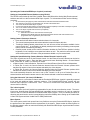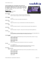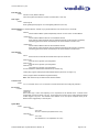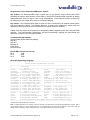
1
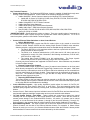
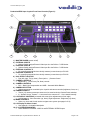
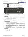
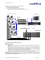
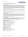
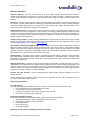
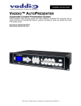
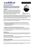
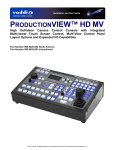
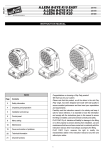
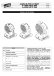
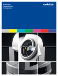
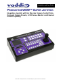
Installation and User Guide
Camera and Electronic Products for Integrators
PRODUCTIONVIEW™ SUPER JOYSTICK
Integration Joystick with Six Discrete Camera Control Ports,
On-board Camera Presets, LCD Preview Monitor and External
Control Capability
©2007 Vaddio - All Rights Reserved. ProductionVIEW Super Joystick - Document 341-565 Rev B.
ProductionVIEW Super Joystick
Overview:
The Vaddio™ ProductionVIEW Super
Joystick is a unique integration joystick
contoller
that
is
based
on
the
ProductionVIEW
series
of
camera
controllers. The Super Joystick has six
individual RS-232C camera control ports for
direct control of PTZ cameras which
eliminates the need for daisy chain control
cabling. The camera control ports are on
RJ-45 connectors which easily connect to
Figure 1: ProductionVIEW Super Joystick
the Vaddio EZCamera™ cabling packages
using a Cat. 5 wiring standard.
Each of the six camera control ports will auto-configure based on the robotic PTZ camera system
connected to that port upon boot up. Whether it is a Vaddio, Sony® or Canon® PTZ camera system the
ProductionVIEW Super Joystick senses the cameras and provides for seamless control of the camera
functions. Each of the six cameras attached has been supplied with 12 internally stored camera presets
effectively removing the internal preset limitations of the camera. Each of the six cameras attached can
also be adjusted individually for the operating environment with adjustments for auto/manual focus,
auto/manual brightness, backlight compensation and one push automatic white balance.
The ProductionVIEW Super Joystick has two rows of six external control switches which can be used in a
variety of ways. These switches are tied to trigger outputs and can be used to control external video
switchers with contact closures or tally lights for studio applications. The Super Joystick also has
provision for external control of select HD switchers/mixers with built-in RS-232 codes in the system
menu. And like the ProductionVIEW FX, the ProductionVIEW Super Joystick console has a 4” LCD
preview monitor is built-in. Overall, the ProductionVIEW Super Joystick is a unique and advanced
camera controller that is unmatched in today’s market for functionality, convenience and value.
Intended Use:
Before operating the Vaddio ProductionVIEW Super Joystick, please read the entire manual thoroughly.
The system was designed, built and tested for use indoors, and with the provided power supply and
cabling. The use of a power supply other than the one provided or outdoor operation has not been tested
and could damage the camera and/or create a potentially unsafe operating condition.
Save These Instructions:
The information contained in this manual will help you install and operate your Vaddio ProductionVIEW
Super Joystick. If these instructions are misplaced, Vaddio keeps copies of Specifications, Installation
and User Guides and most pertinent product drawings for the Vaddio product line on the Vaddio website.
These documents can be downloaded from www.vaddio.com free of charge.
Important Safeguards:
Read and understand all instructions before using. Do not operate any device if it has been dropped or
damaged. In this case, a Vaddio technician must examine the product before operating. To reduce the
risk of electric shock, do not immerse in water or other liquids and avoid extremely humid conditions.
Use only the power supply provided with the ProductionVIEW system.
Use of any unauthorized power supply will void any and all warranties.
UNPACKING:
Carefully unpack and identify the following parts from the packaging.
• One (1) ProductionVIEW Super Joystick Camera Control Console
• One (1) Vaddio PowerRite 18 VDC, 2.75A Power Supply
• One (1) Vaddio AC Cord Set
• Documentation and Manuals
ProductionVIEW Super Joystick Manual 341-565 Rev. B
Page 2 of 16
ProductionVIEW Super Joystick
Key Technical Features:
• Camera Auto-Sensing - The ProductionVIEW Super Joystick is capable of identifying through autosensing of each camera attached. Control codes for the following cameras are built-in:
• Vaddio WallVIEW™ Series Cameras* based on the following PTZ Camera Platforms:
• Vaddio HD-18, Canon VC-C50i& VC-C50iR, Sony EVI-HD1, EVI-D30, EVI-D100 & EVID70, BRC-300, BRC-H700, BRC-Z700
• Vaddio CeilingVIEW™ 70 PTZ Series Cameras*
• Vaddio HideAway Series Cameras*
• Vaddio Model Series and PTZCam Series Cameras*
• Vaddio Add-A-Cam™ PRO Series Camera Systems*
• Sony EVI-HD1, EVI-D30, EVI-D100 & EVI-D70, BRC-300, BRC-H700, BRC-Z700*
• Canon VC-C50i & VC-C50iR*
*IMPORTANT NOTE: Specifications are subject to change. There are a small number of commands on
the ProductionVIEW Super Joystick that will not operate with certain camera platforms. For a list of
control exceptions, please contact Vaddio Technical Support.
•
•
•
•
•
Control of External Video Switchers or other Control Devices
• Built-in RS-232 Codes
The ProductionVIEW Super Joystick has RS-232 codes built-in to the console to control the
Edirol® V-44SW, Extron® ISS-506 and the Analog Way® Eventix EVX8022 video switchers.
Switcher selection, configuration and transition times are handled through the Menu System.
• The Extron ISS-506 is a 6x2 seamless switcher that lines up well with the 6x2 external
control switches on the front panel.
• The Edirol is an 8-channel switcher/mixer (4 SD video and 4 HD video) and can be
configured for control of 6 of the 8 channels in the following combinations; 3-SD & 3-HD,
4-SD & 2-HD or 4-HD & 2SD.
• The Analog Way Eventix EVX8022 is an 8x2 switcher/mixer. The Super Joystick
switches only the first six inputs, effectively using it as a 6x2 configuration.
Currently only these switchers are supported for RS-232 control. Other switchers may be added
in future firmware releases.
• External Triggers/Tally Contacts
The ProductionVIEW Super Joystick has 2 rows of 6 external control buttons on the front panel
which directly correspond to the External Triggers/Tally Contacts on the rear panel. With these
contact closures, video switchers such as the Extron SW series switchers can be controlled from
the front panel buttons of the Super Joystick. These triggers can be configured as active high or
active low. The contacts are latching, TTL type and are not relays and no voltage should be
applied to these triggers at any time.
• Reporting RS-232 Button Pushes
The button pushes on the front panel can also be reported to the RS-232 port allowing for use
with an external control system to translate the RS-232 out of the ProductionVIEW Super Joystick
to any other RS-232 controllable device available.
3-Axis Hall-Effect Joystick - High quality Hall-Effect joystick allows for control of Pan/Tilt (X/Y
coordinates) and the Zoom function (twist for Z or zoom axis). This non-contacting joystick uses
industrial quality magnets and sensors, providing solid, consistent performance throughout its entire
lifetime.
Camera Control - Each camera input has individual control for Pan/Tilt/Zoom and auto/manual focus,
auto/manual brightness, backlight compensation and one-push automatic white balance.
72 Total Camera Presets - Dual Mode - Twelve presets per camera input channel are stored
internally and are not dependent on the internal presets of the camera. There are two modes for
camera preset storage in the ProductionVIEW consoles. All twelve (12) presets can be stored
internally, or six can be stored in the camera (1 through 6) and six stored internally (7 through 12).
Storing presets in the cameras allows for quicker switching since position feedback is not needed.
Speed Switching Modes - The Super Joystick can be set so the External Control A or the External
Control B buttons can be tied to the Camera Selection buttons. For example, in Select follows
External A mode (Sel Follow Ext A), the Camera Selection buttons follow the External A button pushes
which transfers full camera control to that camera selected by the A bus buttons.
ProductionVIEW Super Joystick Manual 341-565 Rev. B
Page 3 of 16
ProductionVIEW Super Joystick
ProductionVIEW Super Joystick Front Panel Controls (Figure 2):
1
3
2
4
14
5
6
13
12
11
10
9
8
7
1) MASTER POWER (system on/off)
2) EXTERNAL VIDEO A
• Selector Switch assigns External Video Input A to the Built-in 4” LCD Monitor
3) EXTERNAL VIDEO B
• Selector Switch assigns External Video Input B to the Built-in 4” LCD Monitor
4) EXTERNAL CONTROL A
• For controlling external devices via tally contacts (contact closure) or RS-232
5) EXTERNAL CONTROL B
• For controlling external devices via tally contacts (contact closure) or RS-232
6) HALL EFFECT JOYSTICK
• Pan (left, right), Tilt (up, down), Zoom (twist +, -) Camera Control
7) CAMERA CONTROLS
• Brightness (+, -) and Focus (Far, Near) controls
8) CAMERA CONTROLS
• BLC – Back Light Compensation and AWB – Automatic White Balance
9) CAMERA SELECTION
• Selects camera to be controlled by the Joystick and camera controls (brightness, focus, etc.)
10) CAMERA PRESETS
• Twelve (12) camera presets per camera can be saved under the Camera Preset switches
• In “6InCam 6Local”, Presets 1 - 6 are stored in the cameras & 7 - 12 are stored internally
11) LCD DISPLAY CONTROLS (recessed mini screw driver adjustments on front edge)
• Left Adjustment - Color Saturation (up, down), Right Adjustment - Brightness (up, down)
12) MENU CONTROLS
• Select, up, down and Cancel used to navigate menu system (see pages 9 & 10)
13) LCD Display for Menu Control
• See Appendix 1 for detailed description
14) 4” LCD PREVIEW MONITOR
• Select between EXTERNAL VIDEO A and EXTERNAL VIDEO B inputs
ProductionVIEW Super Joystick Manual 341-565 Rev. B
Page 4 of 16
ProductionVIEW Super Joystick
ProductionVIEW Super Joystick Back Panel I/O and Controls (Figure 3):
1
2
7
Pin 6: GND
Pin 7: TXD
Pin 8: RXD
3
Pin 2: TX
Pin 3: RX
Pin 5: GND
4
5
6
1) POWER INPUT
• Use only the 18 VDC, 2.75A power supply provided with the ProductionVIEW Super Joystick.
Use of any other power supply may cause damage to the ProductionVIEW and to the
products attached.
• Connector 5.5mm OD, 2.5mm ID, positive center
2) 3-AXIS HALL-EFFECT JOYSTICK
• Pan/Tilt/Zoom Control, Side view - shown with rubber boot.
3) CAMERA CONTROL PORTS on RJ-45 connectors
• One camera control port per camera (no daisy-chaining required)
4) RS-232 CONTROL PORT
• DB-9 for RS-232 control of internal functions (Pin 2 = TX, Pin 3 = RX, Pin 5 = GND) for use
with external controllers or external production switchers
5) EXTERNAL CONTROL TRIGGERS/TALLYS
• For use with tally lights or external devices (i.e. video switchers or control systems). These
external control contacts correspond directly to front panel EXTERNAL CONTROL A (1
through 6) and EXTERNAL CONTROL B (1 through 6) switches on the front panel.
• External Control Triggers/Tally contacts are latching, TTL type. These triggers are not relays
and no voltage should be applied to these triggers at any time. The triggers are configurable
as Active High or Active Low.
6) EXTERNAL VIDEO INPUTS (A & B)
• Composite video inputs on BNC connectors, 1 V p-p, and 75Ω for display on built-in 4”
preview monitor.
7) RJ-45 Pin–outs
• Pin-out reference for RS-232 control over Cat-5 (Cat. 5e) cabling
• Pin 6: GND
• Pin 7: TXD
• Pin 8: RXD
ProductionVIEW Super Joystick Manual 341-565 Rev. B
Page 5 of 16
ProductionVIEW Super Joystick
First Time Set-up with the ProductionVIEW Super Joystick:
ProductionVIEW Super Joystick was designed to be exceptionally easy to use and operate right out of the
box. The controls are intuitive and logical and the pin-outs are printed on the back panel.
Getting Started:
To start using the ProductionVIEW Super Joystick, connect the RS-232 Camera Control Ports on the
Super Joystick to the RS-232 inputs on the cameras, turn on the cameras and let them home, then turn
on the Super Joystick. The Super Joystick will scan each of the cameras connected and automatically
load the appropriate RS-232 codes for control of each camera. Any mix of up to six (6) compatible
camera systems can be used concurrently on the system (see Figures 4 and 5). In all cases, video would
be routed to an external switcher/mixer.
Figure 4: Basic System Configuration - Standard Definition Video
•
•
•
Cameras are controlled by the Super Joystick
Video is handled by an external video switcher
External Switcher is controlled by the Super Joystick via closures
Video
Extron SW Series Switcher
ProductionVIEW
Super Joystick
Video
Contact
Closures
Power
Supply
RS-232
QC
QC
Video &
Power
Video &
Power
RS-232
QC
RS-232
WallVIEW
50i PTZ
RS-232
QC
QC
Video &
Power
Quick-Connect PRO
Video &
Power
RS-232
Video &
Power
WallVIEW 50i
HideAway PTZ
Video &
Power
RS-232
WallVIEW
100 PTZ
WallVIEW 300 PTZ
WallVIEW
70 PTZ
WallVIEW HD1
ProductionVIEW Super Joystick Manual 341-565 Rev. B
Page 6 of 16
ProductionVIEW Super Joystick
Figure 5: System Configuration - High Definition Video
•
•
•
Cameras are controlled by the Super Joystick
Video is handled by an external video switcher
External Switcher is controlled by the Super Joystick via RS-232
•
System is shown with Edirol V-44SW In Edirol V-44SW Mode (4HD - 2SD)
WallVIEW HD1 Camera Systems
HD Video Monitor
Power and
HD Video
Quick-Connect Pro HD1
HD Video
HD Video
Edirol V-44SW
ProductionVIEW Super Joystick
In Edirol V-44SW Mode (4HD - 2SD)
RS-232
RS-232 Codes for Edirol
V-44SW are Built-in
RS-232
Operating the ProductionVIEW Super Joystick:
Master Power Switch
• When the Master Power Switch is powered down, all of the attached cameras will be placed in
standby.
• When the Master Power Switch is powered up, all attached cameras will activate and select
default camera and preset information as defined in the menu. The ProductionVIEW Super
Joystick will scan the inputs for camera type and video signal type and auto-configure
accordingly. This can take up to one minute and is normal operation.
• To power down the ProductionVIEW, press and hold the button for 1 second. This feature
eliminates the accidental powering down of the system if the Power switch is bumped.
Important Note: When the camera control ports are changed or reconfigured, the ProductionVIEW
Super Joystick must be restarted (power cycled) or the cameras must be rescanned for type of camera to
allow reloading of the proper control codes.
ProductionVIEW Super Joystick Manual 341-565 Rev. B
Page 7 of 16
ProductionVIEW Super Joystick
Operating the ProductionVIEW Super Joystick (continued):
Setting-up Compatible External Switchers using RS-232
The RS-232 control codes for the Edirol V-44SW, Extron ISS-506 and the Analog Way Eventix external
switchers are built-in to the ProductionVIEW Super Joystick. To Activate these codes use the following
procedure:
1.
2.
3.
4.
5.
6.
7.
Go to the Menu (see page 10) under Video Switcher and select the desired switcher mode.
The next item in the menu is the transition time, set this to the desired time.
Turn off the ProductionVIEW Super Joystick
Connect the external video switcher to the RS-232 Control Port (DB-9) on the back of the Super Joystick.
Turn on the external switcher and let it boot up completely.
Turn on the Super Joystick and let it boot up completely.
Test for proper operation
a. External Control A row will control the Preview inputs
b. External Control B will control the Program assignment with the Take and Transition Time
programmed into a single button push on that row.
Setting Camera Presets per Channel:
• Press and hold the desired camera selection button for 4 seconds.
• The unused camera presets and camera selection button will flash at this time.
• Touching a flashing camera preset button, the unit will store all the information available via the
camera at this time. A non-flashing or already saved preset location (not-flashing camera preset
button) can be overwritten by touching it.
• Camera presets contain all the camera information besides the Pan/Tilt/Zoom position including
brightness, focus, backlight, zoom-speed and others as well. The particular control saved under
each camera preset is a function of the parameters available on a per camera basis.
Setting the Speed Switching (Camera Selection follows External Control A or B):
The Super Joystick can be set so the External Control A or the External Control B buttons can be tied to
the Camera Selection buttons. Enter the Menu system and locate Switching Modes. Choose Manual
mode, “Follow Ext. A” mode, or “Follow Ext. B” mode.
• In Manual mode, Camera Selection, External Control A and External Control B are all independent.
• In Follow Ext. A mode, the Camera Selection buttons follow the External A button pushes which
transfers full camera control to that camera selected by the A bus buttons.
• In Follow Ext. B mode, the Camera Selection buttons follow the External B button pushes which
transfers full camera control to that camera selected by the B bus buttons.
This mode essentially allows the end user to set up Ext. Control A or B up as a Preview Bus with an
external switcher and transfer camera control to the camera selected on that bus automatically.
Using the Onboard 4” (10.16cm) LCD Monitor:
The LCD monitor is a convenience feature and the ProductionVIEW Super Joystick is generally expected
to be used with additional higher resolution monitors. The ProductionVIEW Super Joystick has two
External Video inputs as a convenience. Note: The LCD is covered with a thin protective film, please
remove this film carefully.
The 3-Axis Joystick:
Within the menus, the 3-axis joystick is programmable for pan, tilt and zoom direction control. The zoomin/zoom-out, tilt-up/tilt-down and pan-left/pan-right commands can be inverted on all 3-axis to customize
control of the PTZ cameras attached to ProductionVIEW Super Joystick. On a per camera port basis, tilt
direction and pan direction can be inverted allowing maximum flexibility when setting up the Vaddio AddA-Cam PRO system with the Vaddio Pan/Tilt PRO pan/tilt head.
Menu System:
The menu system used is both powerful and very flexible to set-up the ProductionVIEW Super Joystick to
the preferences of the operator and the requirements of the system. Please review the Menu System on
the following pages in order to maximize familiarity with ProductionVIEW Super Joystick and the functions
of each parameter.
ProductionVIEW Super Joystick Manual 341-565 Rev. B
Page 8 of 16
ProductionVIEW Super Joystick
ProductionVIEW Super Joystick Menu System Structure
The ProductionVIEW Super Joystick has a back lit, 2-line LCD
that displays the system menus. The menus are traversed with
the up/down arrows, select and cancel buttons. The menu
structure is as follows:
Menu Structure:
st
1 Screen
Menu
Section
ProductionVIEWSJ
T01.00.01
Rescan Cameras
>Select
>Start - Rescans control ports 1 through 6 to find the cameras connected
Rescan is required if a change is made to the inputs of the ProductionVIEW
Default Camera
>Select
> 01 – 06
Selects camera 1 through 6 as the default camera (default is 01)
Default Preset
>Select
> 01 – 12
Assigns camera preset 1 through 12 as Default Preset on the default camera (default is 01)
PanSensitivity
>Select
>01 – 24
Sets the pan sensitivity of the joystick - Lowering the value reduces joystick sensitivity (default is 24).
TiltSensitivity
>Select
>01 – 24
Sets the tilt sensitivity of the joystick - Lowering the value reduces joystick sensitivity (default is 24).
Pan Speed
>Select
>01 – 24
Sets the Pan Speed on all cameras between internally stored camera presets only (24 is fastest) (default is 18)
(This parameter does not affect the Pan Speed or Pan Sensitivity of the Joystick)
Pan Direction Menu
>Select
>All Ports: Normal or Invert (default is Normal) Inverts the Joystick Pan Direction (Inverted - left = right)
>Port 01: Normal or Invert
>Port 02: Normal or Invert
>Port 03: Normal or Invert
>Port 04: Normal or Invert
>Port 05: Normal or Invert
>Port 06: Normal or Invert
>Return to Main
Set this for the requirements of the Pan/Tilt Head or camera used on a per port basis
Tilt Speed
>Select
>01 – 20 (default is 15)
Sets Tilt Speed on all cameras between internally stored camera presets only (20 is fastest).
(This parameter does not affect the Tilt Speed or Tilt Sensitivity of the Joystick)
Tilt Direction
Tilt Direction Menu
>Select
>All Ports: Normal or Invert (default is Normal) Inverts the Joystick Tilt Direction (Inverted - up = down)
>Port 01: Normal or Invert
>Port 02: Normal or Invert
>Port 03: Normal or Invert
>Port 04: Normal or Invert
>Port 05: Normal or Invert
>Port 06: Normal or Invert
>Return to Main
ProductionVIEW Super Joystick Manual 341-565 Rev. B
Page 9 of 16
ProductionVIEW Super Joystick
Zoom Direction
>Select
>Normal or Invert (default is Normal)
Inverts the Joystick Zoom Direction (Inverted - Clockwise twist = zoom out)
Panel Lights
>Select
>00 through 50
Panel Light Brightness (all lights - 50 is the brightest) (default is 25, off is 00)
Switching Modes (For Camera Selection - Manual or tying Camera Selection to Ext. Control A or Ext. Control B):
>Select
>Manual
Camera Selection Button operate independently from Ext. Control A or Ext. Control B Buttons
> Follow Ext A
Camera Selection Buttons follow Ext. A Control Button Pushes
When assigned, Camera Selection switching follows the External A button selection, immediately
transferring joystick and camera control directly to the camera selected on the Ext. A bus.
> Follow Ext B
Camera Selection Buttons follow Ext. B Control Button Pushes
When assigned, Camera Selection switching follows the External B button selection, immediately
transferring joystick and camera control directly to the camera selected on the Ext. B bus.
Video Switcher
>Select
>None
External Control A and External Control B buttons report out via RS-232
>Edirol 3S, 3H
3 Std. Def. and 3 High Def. Input Configuration
>Edirol 4S, 2H
4 Std. Def. and 2 High Def. Input Configuration
>Edirol 4H, 2S
4 High Def. and 2 Std. Def. Input Configuration
*For use with Edirol V-44SW Multi-Format Switcher (6 channels only)
>Analog Way (supports Analog Way Eventix EVX8022 Switcher) Channels 1 through 6 only.
>Extron (Supports Extron ISS-506 6x2 Integration Switcher)
Note: Other switchers may be added in future firmware releases.
Transition Time
>Select
>0.0 - 4.0 Transition Timer, 0.0 to 4.0 seconds for use with Edirol, Extron and Analog Way Switchers
Ext. Triggers
>Select
>Active High
>Active Low
Select Active High or Active Low depending on the requirements of the attached device. External Control
Triggers/Tally contacts are latching, TTL type. These triggers are not relays and no voltage should be applied
to these triggers at any time. The External Control switches on the front panel correspond directly to the
External Control Triggers/Tally on the rear panel.
System Menu
>Select
>Serial Input
>Select
>Yes or No
Turns on or off serial input (default is Yes or On)
>Serial Echo
>Select
>Yes or No
Turns Serial Echo on or off (default is Yes or On)
ProductionVIEW Super Joystick Manual 341-565 Rev. B
Page 10 of 16
ProductionVIEW Super Joystick
System Menu (continued)
>Clear Memory
>Select
>Start
Clears the camera preset memories and sets all parameters to default settings
>Clear Presets
>Select
>Start
Clears the camera preset memory only
>Serial Info
>Select
>On or Off
Reports button pushes on front panel out the serial port (default is off)
(Does not report joy stick position)
>Power Up Preset
>Select
>Home Camera
>Select - Upon power up, all cameras will go to their home position
>Preset 12
> Select - Upon power up, all cameras will go to Preset 12
>Preset Location
>Select
>All Local
>6 InCam 6 Local
In “All Local” mode, the ProductionVIEW stores all 12 presets internally.
In “6 InCam 6 Local” mode, the presets 1 through 6 will be stored in the cameras.
Presets 7 through 12 will be stored in the ProductionVIEW.
Note: The “6 InCam 6 Local” mode allows for switching video sources when cameras are
moving to preset locations. Since Presets are stored in Camera, the system does not have
to wait for position feedback before allowing another command to be entered.
>Return to Main
>Select
Returns to Main Menu item (System Menu)
General Specifications:
System Part Numbers
System I/O
Joystick
LCD Monitor
LCD Display
Internally Stored Presets
Camera Control Parameters
Power Supply
Weight
Dimensions (H x W x D):
ProductionVIEW Super Joystick
999-5300-000 North America (North American AC Cord Set)
999-5300-001 International (Euro and UK AC Cord Set)
Six (6) RS-232 Camera Control Ports on RJ-45 Connectors
One (1) Master RS-232 Control Port on DB-9F
Six (6) External Control A (Preview) Triggers/Tally on Phoenix Type Connectors
Six (6) External Control B (Main) Triggers/Tally on Phoenix Type Connectors
One (1) Ext. Video A (Preview) Input on BNC Connector
One (1) Ext. Video B (Main) Input on BNC Connector
One (1) Power Connector (Coaxial, Positive Center, 5.5mm OD x 2.5mm ID)
3-Axis, Hall Effect, Non-contacting type
4” (101.6mm) Active Matrix with 960 x 234 Resolution
2-Line Back-lit Display
72 (12 per PTZ camera attached) 2 modes
Local Mode - All 12 Presets are stored in the ProductionVIEW
6 In Camera - 6 Local - The presets 1 through 6 are stored in the camera allowing for
quicker camera switching on those presets. Presets 7 through 12 are stored internally in
the Supper Joystick
Brightness, Focus, AWB (auto white balance) and BLC (back light compensation)
18 VDC 2.75 Amp
7lbs/3.175kg
4” (10.2cm) x 16” (40.6cm) x 10” (25.4cm)
ProductionVIEW Super Joystick Manual 341-565 Rev. B
Page 11 of 16
ProductionVIEW Super Joystick
RS-232 Control of the ProductionVIEW Super Joystick
Key Feature: The ProductionVIEW Super Joystick has six (6) discrete camera control ports which
eliminates the need for daisy-chaining control cabling. With all the ProductionVIEW consoles, all cabling
configurations are home-run type or “star” wiring configurations. Each Channel will auto-configure the
input channel for video signal and control for the camera attached.
Key Feature: The ProductionVIEW Super Joystick can also be controlled by an external control system
such as Crestron® or AMX®. This flexibility allows for a system to be designed for multiple uses and
applications where joystick control of the cameras may only be needed on occasion.
Vaddio uses very simple control protocols to accomplish custom programming with the ProductionVIEW
consoles. The Communication Specification, API and Programming Language are listed below and
definitions are listed on the next page thereafter.
Communication Specification
Communication Speed: 9600 bps (default)
Start bit: 1
Stop bit: 1
Data bits: 8
Parity: None
No Flow Control
Female DB-9 Control Port Pin-outs
Pin 2:
TXD
Pin 3:
RXD
Pin 5:
GND
API and Programming Language*
+----------------------------------------------------------------------------+
|
Vaddio ProductionVIEW Super Joystick
|
+----------------------------------------------------------------------------+
|?
- This menu
|
+--------------- System -----------------------------------------------------+
|Power
x- Power(On/Off)
|Reset
- 'CPU' Reset
|
|Version
- Firmware Version
|ClearAll
- Clear all presets
|
|ExtTrigger x- Sel Active (Low/High)
|Rescan
- Re-Scan for Cameras |
|DspCams
x- List connected cameras
|Config
- List Config Settings|
|DefaultCam x- Set Default Camera(1-6)
|CHAIn
x- CHA Source (1-6)
|
|SetDefault x- Set Default Preset(1-12)
|CHBIn
x- CHB Source (1-6)
|
|Display
x- Display (CHB/CHA/Off)
|SerialEcho x- Echo Serial (Yes/No)|
|SwitchMode x- CamSel->(CHA/CHB/Manual)
|SerialInfo x- Status (On/Off)
|
|TiltMaxSpd x- Tilt Speed Range (1-24
|PanMaxSpd x- Pan Spd Range(1-24) |
|PresetLoc x- Store Preset (InCam/Lcl)
|
|
+--------------- Pan, Tilt, Zoom----------+----------------------------------|
|InvertPan x- Invert Pan Dir(Yes/No)
|PanSpeed
x-Pan Speed(1-24)
|
|InvertTilt x- Invert Tilt Dir(Yes/No)
|TiltSpeed x-Tilt Speed(1-20)
|
|InvertZoom x- Invert Zoom Dir(Yes/No)
|OnCamInit x- (Home/Preset12)
|
+--------------- Camera ------------------+----------------------------------|
|Camera
x- Switch to Camera(1-6)
|Preset
x-Go to Preset(1-12)
|
|Zoom
x- Zoom (In/Out/Stop)
|Store
x-Store Preset(1-12)
|
|Focus
x- Focus(Auto/Near/Far/Stop) |BLC
x-BacklightComp(On,Off)|
|Bright
x- Bright(Auto,Up,Down)
|AWB
x-AutoWhiteBal(On,Off) |
|Move
x- Move(Up,Down,Stop,Left,Right)|Pass(cr)(Camera command string) |
+----------------------------------------------------------------------------+
*Carriage return required after each command
Note: To display this menu on a computer, connect a computer to the RS-232 port of the ProductionVIEW Super Joystick. With a
communication program (i.e. Hyper Terminal) type in ? and carriage return, this menu will be displayed. If this menu does not
display, then the computer port isn’t configured correctly or the cable is either bad or pinned incorrectly.
ProductionVIEW Super Joystick Manual 341-565 Rev. B
Page 12 of 16
ProductionVIEW Super Joystick
Command Structure Definitions
Command
Description
AWB x
(On/Off) Turns auto white balance on or off on controlled camera.
BLC x
(On/Off) Turns backlight compensation on or off on controlled camera.
Bright x
(UP) Turns brightness up one increment, (Down) Turns brightness down one increment, (Auto) restores
auto brightness on controlled camera.
Camera x
(1-6) Switch control function to camera x.
CHAIn x
External Control A (1-6)
CHBIn x
External Control B (1-6)
ClearAll
Clears ALL presets.
Config
Displays the current configuration.
DefaultCam x
(1-6) This camera will be activated at startup
Display x
(CHB/CHA/Off) Selects what will be viewed on the internal LCD screen.
DspCams x
Lists connected cameras
ExtTrigger x
Select active high or active low (Low/High)
Focus x
(Auto) restores auto-focus, (Near) focus near, (Far) focus far, (Stop) stops near and far focus
InvertPan x
(Yes) Changes pan direction on all cameras. (No) Normal direction.
InvertTilt x
(Yes) Changes tilt direction on all cameras. (No) Normal direction.
InvertZoom x
(Yes) Changes zoom direction (No) Normal direction.
Move x
(Up/Down/Stop/Left/Right) Moves or stops controlled camera.
OnCamInit x
(Home/Preset 12) Homes default camera or sends all camera to Preset 12 upon power up
PanSpeed x
(1-24) Changes pan speed on all cameras 24=fastest. This is the pan speed between presets only.
PanMaxSpd x
(1-24) Sets Pan Speed Range - 24 Fastest
Pass(cr)
Passes next string to controlled camera (camera response, if any, is not passed back)
Power x
(On) Starts ProductionVIEW, (Off) Places ProductionVIEW and all controlled cameras into standby mode
Preset x
(1-12) Go to preset x on controlled camera.
PresetLoc x
(InCam/Lcl) Preset location - Local is all 12 internal - InCam is 6 in the cameras and 6 internal
Rescan
Rescans for attached cameras.
Reset
Reboots system
SerialEcho x
(Yes) Serial commands sent to the ProductionVIEW SJ will be echoed back. (No) Not echoed.
SerialInfo x
(On) Shows console button pushes to RS232 host port. These commands the same as the input serial
commands (Off) Does not show these button pushes.
SetDefault x
(1-12) Set Default Preset
Store x
(1-12) Stores preset x for the controlled camera.
SwitchMode x
CamSel - (CHA/CHB/Manual) Sets Camera Selection to follow Ext A or External B button pushes
TiltSpeed x
(1-20) Changes tilt speed on all cameras 20 = fastest. This is the tilt speed between presets only.
TiltMaxSpd x
(1-24) Sets Tilt Speed Range - 24 Fastest
Version
Displays Firmware version installed
Zoom x
(In) Zooms in (Out) Zooms out (Stop) Stops Zoom - On controlled camera.
ProductionVIEW Super Joystick Manual 341-565 Rev. B
Page 13 of 16
ProductionVIEW Super Joystick
Compliance and CE Declaration of Conformity
FCC Part 15 Compliance
This equipment has been tested and found to comply with the limits for a Class A digital device, pursuant
to Part 15 of the FCC Rules. These limits are designed to provide reasonable protection against harmful
interference when the equipment is operated in a commercial environment. This equipment generates,
uses, and can radiate radio frequency energy and, if not installed and used in accordance with the
instruction manual, may cause harmful interference to radio communications. Operation of this equipment
in a residential area is likely to cause harmful interference in which case the user will be required to
correct the interference at his/her own expense.
Operation is subject to the following two conditions: (1) This device may not cause interference, and (2)
This device must accept any interference including interference that may cause undesired operation of
the device.
Changes or modifications not expressly approved by Vaddio can affect emission compliance and could
void the user’s authority to operate this equipment.
ICES-003 Compliance
This digital apparatus does not exceed the Class A limits for radio noise emissions from digital apparatus
set out in the Radio Interference Regulations of the Canadian Department of Communications.
Le présent appareil numérique n’emet pas de bruits radioélectriques dépassant les limites applicables
aux appareils numeriques de la classe A préscrites dans le Règlement sur le brouillage radioélectrique
édicte par le ministère des Communications du Canada.
European Compliance
This product has been evaluated for Electromagnetic Compatibility under the EN 55103-1/2 standards for
Emissions and Immunity and meets the requirements for E4 environment.
This product complies with Class A (E4 environment). In a domestic environment this product may cause
radio interference in which case the user may be required to take adequate measures.
Standard(s) To Which Conformity Is Declared:
EMC Directive 89/336/EEC
EN 55103-1
Electromagnetic Compatibility - Emissions
EN 55103-2
Electromagnetic Compatibility - Immunity
EN 55022A
Conducted and Radiated Emissions
EN 61000-3-2 Limits for Harmonic Current Emmissions
EN 61000-4-2 Electrostatic Discharge
EN 61000-4-3 Radiated Immunity
EN 61000-4-4 Electrical Fast Transients
EN 61000-4-5 Surge Immunity
EN 61000-4-6 Conducted Immunity
EN 61000-4-8 Power Frequency Magnetic Field
EN 61000-4-11 Voltage Dips, Interrupts and Fluctuations
Annex A
Magnetic Field Immunity
ProductionVIEW Super Joystick Manual 341-565 Rev. B
Page 14 of 16
ProductionVIEW Super Joystick
Warranty Information:
Hardware* Warranty - One year limited warranty on all parts. Vaddio warrants this product against defects in
materials and workmanship for a period of one year from the day of purchase from Vaddio. If Vaddio receives notice
of such defects during the warranty period, they will, at their option, repair or replace products that prove to be
defective.
Exclusions - The above warranty shall not apply to defects resulting from: improper or inadequate maintenance by
the customer, customer applied software or interfacing, unauthorized modifications or misuse, operation outside the
normal environmental specifications for the product, use of the incorrect power supply, improper extension of the
power supply cable or improper site operation and maintenance.
Vaddio Customer service – Vaddio will test, repair, or replace the product or products without charge if the unit is
under warranty and is found to be defective. If the product is out of warranty, Vaddio will test then repair the product
or products. The cost of parts and labor charge will be estimated by a technician and confirmed by the customer prior
to repair. All components must be returned for testing as a complete unit. Vaddio will not accept responsibility for
shipment after it has left the premises.
Vaddio Technical support - Vaddio technicians will determine and discuss with the customer the criteria for repair
costs and/or replacement. Vaddio Technical Support can be contacted through one of the following resources: e-mail
support at [email protected] or online at www.vaddio.com.
Return Material Authorization (RMA) number - Before returning a product for repair or replacement, request an
RMA from Vaddio’s technical support. Provide a technician with a return phone number, e-mail address, shipping
address, and product serial numbers and describe the reason for repairs or returns as well as the date of purchase
and proof of purchase. Include your assigned RMA number in all correspondence with Vaddio. Write your assigned
RMA number on the outside of the box when returning the product.
Voided warranty – The warranty does not apply if the original serial number has been removed or if the product has
been disassembled or damaged through misuse, accident, modifications, or unauthorized repair. Cutting the power
supply cable on the secondary side (low voltage side) to extend the power to the device (camera or controller) voids
the warranty for that device.
Shipping and handling - Vaddio will not pay for inbound shipping transportation or insurance charges or accept any
responsibility for laws and ordinances from inbound transit. Vaddio will pay for outbound shipping, transportation, and
insurance charges for all items under warranty but will not assume responsibility for loss and/or damage by the
outbound freight carrier. If the return shipment appears damaged, retain the original boxes and packing material for
inspection by the carrier. Contact your carrier immediately.
Products not under warranty - Payment arrangements are required before outbound shipment for all out of
warranty products.
*Vaddio manufactures its hardware products from parts and components that are new or equivalent to new in
accordance with industry standard practices.
Other General Information:
Care and Cleaning
Do not attempt to take this product apart at any time. There are no user-serviceable components inside.
•
Do not spill liquids in the ProductionVIEW Super Joystick
•
Keep this device away from food and liquid
•
For smears or smudges on the console, wipe with a clean, soft cloth.
•
Do not use any strong or abrasive chemicals.
Operating and Storage Conditions:
Do not store or operate the ProductionVIEW Super Joystick under the following conditions:
•
Temperatures above 40°C (104°F) or temperatures below 0°C (32°F)
•
High humidity, condensing or wet environments
•
In inclement weather
•
Dusty environments
•
Under severe vibration
Specifications and Camera Compatibility are Subject to Change.
ProductionVIEW Super Joystick Manual 341-565 Rev. B
Page 15 of 16
ProductionVIEW Super Joystick
Toll Free: 800-572-2011 ▪ Phone: 763-971-4400 ▪ FAX: 763-971-4464
www.vaddio.com
©2007 Vaddio - All Rights Reserved. Reproduction in whole or in part without written permission is prohibited. Specifications and pricing are
subject to change without notice. Vaddio, ProductionVIEW, CeilingVIEW, WallVIEW, EZCamera, Quick-Connect, Add-A-Cam and PowerRite
are registered trademarks of Vaddio, LLC. All other trademarks are property of their respective owners. Form Number 341-565 Rev B.
ProductionVIEW Super Joystick Manual 341-565 Rev. B
Page 16 of 16