1
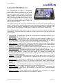
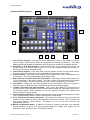
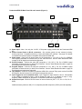
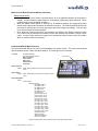
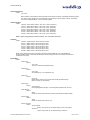
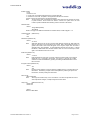
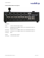
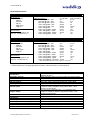
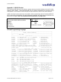
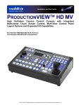
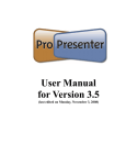
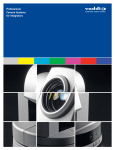
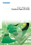
Installation and User Guide
Camera and Electronic Products for Integrators
VADDIO™ PRODUCTIONVIEW™ HD
Camera Control Console with HD/SD Video Switching, Video Transitions,
Up/Down Converting of Inputs and Outputs, Lower Screen Graphics and
Automated Control Functionality
Model Number 999-5600-000 (NTSC)
Model Number 999-5600-001 (PAL)
©2009 Vaddio - All Rights Reserved. ProductionVIEW HD - Document Number 341-759 Rev. C
ProductionVIEW HD
ProductionVIEW HD Overview
The ProductionVIEW HD (Figure 1) incorporates
seamless video switching, camera preset control and
joystick camera control functionality into one of the
most fully featured video consoles on the market
today. In addition, ProductionVIEW HD delivers user
selectable HD or SD inputs, and will up convert or
down convert the output signals to a variety of screen
resolutions and screen formats in component high
definition (HD), standard definition (SD) or RGBHV, all
with only one frame of delay.
Figure 1: ProductionVIEW HD Camera Control Console
Video graphics insertion (i.e. “lower third”) is available through our unique Lower Screen Graphics (LSG)
system. LSG allows users to insert graphics from a variety of graphics programs, including Microsoft®
PowerPoint®, Apple® Keynote®, MediaShout® or virtually any presentation software application. LSG
provides graphics insertion without the added latency or complexity of luminance or chroma keying.
The ProductionVIEW HD control surface is laid out to allow even a novice to operate the system with
minimal training. ProductionVIEW HD is unmatched in today’s camera control, video mixing and video
switching market.
•
•
•
•
•
•
•
•
•
•
Video Switcher -- The internal video switcher can be configured as a traditional video switcher, using
the Take button, or Dual Bus mode.
Dual Bus Mode – Dual Bus allows users to switch two separate programs (i.e. IMAG for live
presentations on the Program output, and a secondary program for a recording of the live event on
the Preview output). The Program output can be a discrete resolution setting from the Preview
outputs. Either set of outputs can be configured for SD, HD or RGBHV video resolution.
Graphic Insertion -- Graphics may be inserted as “lower-thirds” using the Lower Screen Graphics
(LSG) feature. LSG can be set up to cover the bottom ¼,⅓, ½ or full screen, with 10 adjustable steps
of transparency levels between the graphic and the video image behind it.
Anything In / Anything Out – The inputs and outputs have discrete video resolution settings. See the
specifications on page 20 for additional information on all of the resolutions supported.
PTZ Camera Joystick -- The ProductionVIEW HD includes a joystick controller to operate up to six (6)
PTZ cameras directly (without daisy chaining) and the six discrete camera control ports auto-sense
the PTZ camera attached. Vaddio, Sony® and Canon® PTZ cameras are compatible with
ProductionVIEW HD (see the list of specific models). Each input has a camera selector to allow 12
preset PTZ positions to be stored.
Transitions -- On the control surface, buttons for the type of effect (dissolve, wipe or cut) as well as
wipe patterns are selectable. The transition time is adjustable through a knob on the console, from
zero (0) to four (4) seconds.
Automatic Mode -- The console is equipped with an Automatic Camera Switching Mode (for
compatible PTZ cameras on inputs 1 & 2), and when combined with Vaddio’s StepVIEW Mats,
MicVIEW or other trigger devices, allows ProductionVIEW HD to be set up for use without an operator
present.
Tally Outputs -- The ProductionVIEW HD also has six Tally outputs for controlling tally lights on
external sources, such as Vaddio’s WallVIEW CCUs and PreVIEW HD monitors.
Graphic Templates -- A variety of graphic templates are included on a DVD supplied with
ProductionVIEW HD in both Keynote and PowerPoint, to help guide users to create professional
graphics quickly and easily.
Additional Features – Other features include auto/manual focus, auto/manual iris, backlight
compensation and automatic white balance for compatible PTZ cameras.
ProductionVIEW HD Manual 341-759 Rev. C
Page 2 of 24
ProductionVIEW HD
Key Technical Features:
• Camera Auto-Sensing - The ProductionVIEW HD is capable of auto-sensing each PTZ camera
attached. Control codes for the following cameras are built-in:
• Vaddio ClearVIEW HD-18 PTZ Camera
• Vaddio WallVIEW, CCU and PRO Series Cameras
• Vaddio CeilingVIEW 70 PTZ Series Cameras
• Vaddio HideAway Series Cameras
• Vaddio CeilingVIEW Document Cameras
• Vaddio Model Series and PTZCam Series Cameras
• Sony EVI-HD1, EVI-D30, EVI-D100 & EVI-D70 & Sony BRC-300, BRC-Z700 & BRC-H700
• Panasonic AW-HE100
• Vaddio Add-A-Cam and Pan/Tilt PRO
• Canon VC-C50i & VC-C50iR
•
Video Transitions
Video transitions are seamless with exceptional video quality. Transition time is adjustable from zero
(0) to four (4) seconds and include:
• Cross Fades (one image fades into another)
• Wipes (9 different patterns)
• Straight Cuts
• Fade To Black (by pressing, and holding the MIX/FTB button)
Intended Use:
Before operating the Vaddio ProductionVIEW HD, please read the entire manual thoroughly. The system
was designed, built and tested for use indoors, and with the provided power supply and cabling. The use
of a power supply other than the one provided or outdoor operation has not been tested and could
damage the camera and/or create a potentially unsafe operating condition.
Save These Instructions:
The information contained in this manual will help you install and operate your Vaddio ProductionVIEW
HD. If these instructions are misplaced, Vaddio keeps copies of Specifications, Installation and User
Guides and most pertinent product drawings for the Vaddio product line on the Vaddio website. These
documents can be downloaded from www.vaddio.com free of charge.
Important Safeguards:
Read and understand all instructions before using. Do not operate any device if it has been dropped or
damaged. In this case, a Vaddio technician must examine the product before operating. To reduce the
risk of electric shock, do not immerse in water or other liquids and avoid extremely humid conditions.
Use only the power supply provided with the ProductionVIEW HD system.
Use of any unauthorized power supply will void any and all warranties.
UNPACKING:
Carefully remove the device and all of the parts from the packaging.
Unpack and identify the following parts:
• One (1) ProductionVIEW HD Camera Control Console, Part Number 999-5600-000/-001
• One (1) Vaddio PowerRite 18 VDC, 2.78A Power Supply
• One (1) AC Cord Set (US or UK and Europe)
• DVD ROM with templates and sample graphics for Lower Screen Graphics*
• Documentation and Manuals
* User must supply their own compatible version of Keynote or PowerPoint to display and modify
templates on the DVD ROM.
ProductionVIEW HD Manual 341-759 Rev. C
Page 3 of 24
ProductionVIEW HD
ProductionVIEW HD (Figure 2):
10
9
8
1
2
3
4
5
6
7
1. Focus and Iris Controls: Focus and Iris can be adjusted from knobs on the console for real-time
control of these critical functions, when their respective Auto buttons are turned off. Auto White
Balance (AWB) and Backlight Compensation (BLC) functions are available for compatible cameras.
2. Single Bus or Dual Bus Switching: ProductionVIEW HD can be configured as Program and
Preview buses or as discrete video outputs (i.e. one for high resolution IMAG and the other for
delivery to a recording or streaming device).
3. Lower Screen Graphics: Insert “lower third” and other graphics, through our unique LSG function.
A variety of sizes and transparency levels are available through buttons on the console.
4. Picture-In-Picture: Insert video in any quadrant of the program video output to add impact to your
live production. The PIP can be adjusted to three different sizes.
5. Wipe, Fade, Cut, Transition Speed and Fade to Black: Select from a variety of wipe patterns, mix
or cut from buttons on the control console. The Fade to Black (FTB) feature allows the Program
output to fade to black. Transition Speed allows a wipe or fade to be adjusted up to 4 seconds.
6. Take Button: Pressing the Take button switches the input selected from Preview to Program in
Single Bus mode. In Dual Bus mode, it switches the input to the input that is flashing.
7. Joystick PTZ Camera and Speed Controls: Sony, Canon and Vaddio PTZ cameras can be
controlled via the 3-axis Hall-Effect joystick built into ProductionVIEW HD. Adjustable knobs for Pan,
Tilt and Zoom speeds. When the button on top of the joystick is pressed, it will reposition the
selected camera to its home position.
8. Camera Selector and Presets: Select a camera from the top row of buttons, and program (or recall)
up to 12 preset shots per camera, using the camera preset control buttons.
9. 8-Line LCD Screen (for Menus and Status): The internal menu allows the user to configure the
resolution on the outputs, as well as other parameters built into the console. The LCD screen will
also provide status to current settings. See pages 13 to 16 for the menu structures and
programmable functions.
10. Manual and Automatic Modes: In addition to a manual or “operator” mode there is an Automatic
Camera Switching mode for PTZ camera presets assigned to Vaddio input triggers like the
StepVIEW™ mats, AutoVIEW™ IR or TouchVIEW™ buttons.
ProductionVIEW HD Manual 341-759 Rev. C
Page 4 of 24
ProductionVIEW HD
ProductionVIEW HD Back Panel I/O and Controls (Figure 3):
18
11
17
12
16
13
14
15
11. Power Input - Note: Use only the 18 VDC, 2.75A power supply provided with the ProductionVIEW
HD.
12. Camera Control Ports on RJ-45 connectors: One camera control port per camera (no daisychaining required). Compatible with Sony, Canon and Vaddio PTZ cameras. See page 3 for details
on cameras and camera systems compatible with ProductionVIEW HD.
13. Video Inputs: Each input will accept either an SD (composite or Y-C), HD (Y, Pb, Pr) or RGBHV
video signals (selectable via internal menu) on the VGA connector. See the Video Resolutions table
on page 20 for all signals and resolutions supported.
14. Preview Outputs – Delivers the same SD (composite or Y-C), HD (Y, Pb, Pr) or RGBHV signal
(selectable via internal menu) on both VGA connectors. See the Video Resolutions table on page 20
for all signals and resolutions supported.
15. Program Outputs – Delivers the same SD (composite or Y-C), HD (Y, Pb, Pr) or RGBHV signal
(selectable via internal menu) on both VGA connectors. See the Video Resolutions table on page 20
for all signals and resolutions supported.
16. Tally Outputs – Allows for connecting ProductionVIEW HD to external Tally inputs such as PreVIEW
HD monitors, Quick-Connect CCU and other third-party tally sources.
17. Input Triggers for use in Automatic mode - Input Triggers for input channels 1 and 2. Configurable
in two modes (6 triggers for Input 1 and 6 triggers for Input 2, or 12 triggers for input 1 only).
Supports Vaddio AutoVIEW IR, StepVIEW, TouchVIEW and MicVIEW trigger inputs.
18. Control Port Input - DB-9 for RS-232 control of internal functions (Pin 2 = TX, Pin 3 = RX, Pin 5 =
GND).
Vaddio accessory cables for SD (Y-C or composite) and HD component (YPbPr) are sold separately.
ProductionVIEW HD Manual 341-759 Rev. C
Page 5 of 24
ProductionVIEW HD
First Time Set-up with the ProductionVIEW HD:
ProductionVIEW HD was designed to be exceptionally easy to use and operate right out of the box. All of
the Vaddio standards for using video, power and control over Cat. 5 cabling are well documented and are
in the manual and available free of charge from the Vaddio website.
Getting Started:
Connect all of the cameras, monitors and peripheral devices to ProductionVIEW HD. The back panel has
standard VGA connectors, and Vaddio offers three different break out cables – one for SD video inputs
(either Y-C or composite) and two cables (3 ft. or 6 ft.) for high resolution video (YPbPr or RGBHV). See
Figures 2 & 3 for additional information.
NOTE: If only one video monitor or projector will be connected to the Preview and/or Program outputs, use the top
connector labeled Primary. The secondary output will deliver 6 dB of gain, if nothing is connected to the primary
output.
On the next page is a diagram showing how to connect a Vaddio WallVIEW H700 CCU to
ProductionVIEW HD.
Once you have connected all of your inputs, outputs and the PowerRite power supply, plug the AC cord
into an outlet. ProductionVIEW HD will boot up and scan for cameras. As ProductionVIEW HD boots up,
it will automatically scan each input to confirm which ports have compatible PTZ cameras or Add-A-Cam
systems connected. After boot up, a menu will appear on the blue LCD screen.
Configuring Output Resolutions
On the LCD screen, a chevron (>)
will be displayed next to the menu
item that is currently selected.
Press the Arrow Down Button (↓)
adjacent to the LCD screen, until the
chevron is next to “VIDEO OUTPUT
MENU” and then press the SELECT
button.
Select
PROGRAM
OUTPUT, which will display your
options for video output resolution for the PROGRAM OUTPUT. Arrow down to the appropriate resolution
that is compatible with your video monitor, then press the SELECT button. Then, press the CANCEL
button to exit out to the previous menu.
Repeat the process for your Preview Output. Once you have selected the Program and Preview output
resolutions, press the CANCEL button to get back to the Main Menu. For additional information on the
menu tree structure, see pages 13 to 16 for additional information.
Configuring Input Resolutions
From the Main Menu, press the down arrow button, to move the chevron to VIDEO INPUT MENU, and
then press the SELECT button. If all input devices have the same resolution (i.e. 1080i / 59.94), then
select ALL PORTS. If not all inputs have the same resolution, then press the down arrow button to the
first input with a video device attached, and press SELECT. Choose the appropriate video resolution for
the video device connected to the input, and then press SELECT. Press the CANCEL button to exit the
resolution setting for the input. Repeat the process for all video inputs.
NOTE: Whether an input is a PTZ camera, or other peripheral device, the input signal will need to be configured to
the proper video resolution of the device connected.
Additional Programming
Review the ProductionVIEW HD Menu Structure on page 13 for additional information on programming
specific parameters. For API and Programming Language, see information beginning on page 21.
ProductionVIEW HD Manual 341-759 Rev. C
Page 6 of 24
ProductionVIEW HD
Figure 5: Optional HD Accessory Cable
(3 or 6 foot length)
Figure 4: Optional SD Accessory
Cable (Y-C & Composite)
Vaddio Accessory Cable Part Numbers
440-5600-000 – 15-pin to SD (Y-C / CVBS) breakout cable (female BNCs – 1 foot)
440-5600-001 – 15-pin to HD Component (YPbPr/RGBHV) breakout cable (male BNCs – 3 foot)
440-5600-002 – 15-pin to HD Component (YPbPr/RGBHV) breakout cable (male BNCs – 6 foot)
440-5600-003 – 15-pin to HD Component (YPbPr/RGBHV) breakout cable (female BNCs – 7 inch)
NOTE: Strain relief for the 15-pin connectors is recommended on the back of the ProductionVIEW HD.
Figure 6:
Sample configuration of a WallVIEW CCU connected to
ProductionVIEW HD, with video, control and tally cabling.
RS-232
Control
Tally
Video
WallVIEW
CCU HD-18
ProductionVIEW HD Manual 341-759 Rev. C
Page 7 of 24
ProductionVIEW HD
Figure 7: In-depth ProductionVIEW HD Camera Control System Examples
The ProductionVIEW HD is ideal for controlling multiple cameras or more complicated systems (external
control system, SD and HD PTZ cameras, a computer and DVD player, with StepVIEW mats and an
AutoVIEW IR as external triggers) as outlined above.
ProductionVIEW HD Manual 341-759 Rev. C
Page 8 of 24
ProductionVIEW HD
Operating the ProductionVIEW HD:
Most of the console functions and controls are easy and intuitive. Over the next few pages there are
details on how the different functions operate.
Camera Controls
The controls that can be used to adjust a PTZ
camera are highlighted in the diagram to the
right (mechanical functions are in gray, and
electronic in blue).
See notes below for
additional information.
ProductionVIEW HD is shipped with “Select
Follow Preview” as the default setting. In this
configuration, the camera that is selected on the
Preview bus will automatically choose the
appropriate Camera Select button in the upper
right corner. In this example, Input 1 is a PTZ
camera on the Preview bus and the Camera
Select is illuminated on Input 1 (“1” with a circle
around the number).
3-Axis Joystick: Within the menus, the 3-axis joystick is programmable for pan, tilt and zoom direction
control. The zoom-in/zoom-out, tilt-up/tilt-down and pan-left/pan-right commands can be inverted on all 3axis to customize control of the PTZ cameras attached to ProductionVIEW HD. Pan, Tilt and Zoom
speed can be adjusted on controls above the joystick. The PTZ speeds are on a per-camera basis.
Preset Location Storage Options: This feature allows the user to store 12 camera presets in the
ProductionVIEW HD or have the option of storing 6 camera presets (1 through 6) in the camera and 6
presets (7 through 12) in the ProductionVIEW HD. When storing the presets in the camera, the user is
allowed to speed switch camera presets. Please see the ProductionVIEW HD Menu Structure, System
Menu for access to the Preset location parameter.
Setting Camera Presets: To program PTZ camera presets, press and hold the Camera Select button for
three seconds. The Camera Presets buttons (1 thru 12) will begin to flash. Move the camera to the
desired PTZ position, and select one of the Camera Presets buttons to store the position. Repeat the
process for each preset position that is required to be stored, up to 12 total positions per PTZ camera. A
non-flashing preset button has a location stored, but can be overwritten.
Select Follows Preview: When “Select Follows Preview” is activated, the camera selected for control is
the camera selected by the Preview bus selection. The operator selects the camera to be previewed, and
control (joystick and camera control) is transferred to that camera. The default position for this feature
from the factory is ‘on’.
Focus, Iris, Auto White Balance and Backlight Compensation: When the Auto Focus or Auto Iris buttons
are turned off, the manual focus and iris knobs can be used to adjust these functions on compatible PTZ
cameras that are connected to the system. Auto White Balance (AWB) automatically adjusts the
camera’s color settings based on lighting and other factors. Backlight Compensation (BLC) opens the iris
to allow objects in front of windows and other bright backgrounds to be more visible.
Dual Bus Mode: Select Follow Preview is disabled when the system is set for Dual Bus mode.
NOTES: 1) Camera presets contain all the camera information besides the Pan/Tilt/Zoom position including
brightness, focus, backlight, zoom-speed and others as well. 2) The particular control saved under each camera
preset is a function of the parameters available on a per camera basis. 3) Camera presets will not save specific
settings of a Quick-Connect CCU, if it is connected to ProductionVIEW HD. 4) Backlight Compensation can only be
used when the Auto White Balance is turned on. 5) Auto White Balance is a function that will not work with the
Panasonic AW-HE100, as well as the WallVIEW HE100 cameras.
ProductionVIEW HD Manual 341-759 Rev. C
Page 9 of 24
ProductionVIEW HD
Wipe, Dissolve or Cut
To set up the switcher to transition from the
current input selected as the Program output to
another input, select a different video signal on
the Preview bus. In the example to the right,
Program is on Input 1 and Preview is on Input 3.
Select the type of effect (wipe, cut or mix) that
the switcher will use to transition from one input
to the other. Pressing the Take button will
execute the transition from one input to the
other, using the selected transition (mix, cut or
wipe).
Changing Effect: To change the type of transition -- Wipe, Cut or Mix -- select that effect above the Take
button.
Changing Transition Speed: Both the Mix and Wipe effects can be adjusted from .01 to 4 seconds, by
adjusting the Transition Speed knob, which is located above the Mix button.
Transitions in Dual Bus Mode: Both Program and Preview will allow for transitions (the same type of
transition will occur on both outputs). To select the input that will replace the current output on each bus,
press the input that will become the next signal sent to the output for either both buses, or one bus. The
signal that each bus will switch to will flash. Press the Take button, and the transition will occur from the
current output to the next one on each bus, one after the other. The other option for making a transition is
to press the flashing button a second time, which will execute the switch from the current (solid lit button)
video signal, to the next video signal (flashing button).
Fade To Black
The Fade To Black feature allows a user to fade
the Program and Preview outputs to black, and
then fade the outputs up from black. To have
the outputs fade to black, press and hold the
MIX/FTB button for more than one second. The
outputs will start fading to black.
At the point where it is appropriate to fade up
from black, press and hold the MIX/FTB button
again, and the Preview and Program outputs will
return to their selected video inputs that were
selected prior to pressing FTB.
FTB Speed: The speed at which the signal fades in and out can be adjusted through the internal menu of
ProductionVIEW HD. Speed ranges from 01 to 40 (.01 to 4.0 seconds). See the ProductionVIEW HD
Menu Structure section of this manual for the location of the internal menu that adjusts FTB timing.
Dual Mode FTB: Pressing and holding FTB in Dual Mode allows both the Preview and Program outputs
to fade to black, just as it will in Single Mode operation.
Note: FTB transition time is adjusted via the internal menu of ProductionVIEW HD, not from the Transition Speed knob.
ProductionVIEW HD Manual 341-759 Rev. C
Page 10 of 24
ProductionVIEW HD
Lower Screen Graphics
Preparing to display Lower Screen Graphics on
ProductionVIEW
HD,
first
select
your
“background” video input (typically a live
camera) on the Program bus, and then select
the input that has the computer graphics that are
to be displayed, on the Preview bus. In the
example to the right, the background is Input 1
on Program, and the computer is on Input 6.
To initiate the Lower Screen Graphic, press one
of the LSG buttons on either bus, and the
graphic will appear.
Transparency Level: To increase or decrease the transparency of the graphic overlay, press and hold the
Transparency Level button down. The system will toggle through the levels to allow the user to select the
level that is appropriate for the graphics.
Lower Screen Size: To increase or decrease the size of the graphic overlay, press and hold the Lower
Screen Size button. The system will toggle through the sizes (bottom ¼, ⅓, ½ or full screen), to allow the
user to select the level that is appropriate for the graphics that have been created.
Increasing/Decreasing Transparency Level and Lower Screen Size: When LSG is activated, pressing the
PIP Upper Left Button will allow both Transparency Level and Lower Screen Size to increase when either
button is pressed. Pressing the Lower Left PIP button will allow the LSG controls to decrease to
decrease when either button is pressed. Note: This feature does not work in Dual Bus mode.
LSG In Dual Bus Mode: In Dual Bus Mode, where seamless switched outputs with effects and transitions
can be delivered out of both the Preview and Program outputs, select the Input on each bus that will be
the “background” image. Next, select the input that has the computer graphics that will be displayed (the
second button that is pressed on each bus will flash). Press the LSG buttons on the Program and
Preview buses. The graphics will placed on each output seamlessly.
LSG Presets: Preset configurations for LSG can be set up utilizing the Camera Preset buttons in the
upper right of the console. Up to 12 preset configurations of lower screen size and transparency level
can be programmed. To do this, with LSG mode turned on, simply set a Lower Screen Size and
Transparency Level. Next, press and hold one of the 12 Camera Preset buttons for approximately 4
seconds. The Lower Screen Size and Transparency Level will be stored in that preset position, much like
a camera preset can be stored in the system. Change the Transparency Level and/or Size and store the
new preset in one of the other 12 Camera Preset selector buttons. A total of 12 LSG presets can be
stored in the system. The last LSG preset position displayed will be the one recalled when LSG is turned
back on. Currently, the preset positions for the LSG can only be changed when LSG is turned on.
Note:
A DVD containing sample graphics in both Keynote and PowerPoint is supplied with
ProductionVIEW HD. The sample graphics provide users with an easy way of getting started creating
graphics for their own live productions.
ProductionVIEW HD Manual 341-759 Rev. C
Page 11 of 24
ProductionVIEW HD
PIP Display
To set up and display a Picture-In-Picture
on the Program output, select the input that
will be the “background” on the Program
bus. Select the video input that will be the
picture-in-picture, or in the “window” on the
screen. In the example to the right, the
background is Input 1 on the Program bus
and Input 3 is the window on the Preview
bus.
Next, select the corner that the PIP window
will show up in, using the P.I.P. Positioning
buttons (upper left, upper right, lower left
and lower right). In the illustration to the
right, the lower left is selected.
To display the PIP, press either of the PIP buttons, and the PIP will appear on the screen. Input 3 will
now be displayed in a window in the lower left corner of the screen.
Changing PIP Size: To change the size of the PIP (small, medium or large), press and hold the PIP
Positioning button and ProductionVIEW HD will toggle through the sizes.
PIP In Dual Mode: If ProductionVIEW HD is set up for Dual Mode (independently switched live feeds on
Preview and Program buses), select the background source. Next, select the PIP source, which will
flash. Press the PIP button for that specific bus, and the window will be displayed. Press the PIP button
to remove the window from the screen. PIP is discrete for the Program and Preview buses when the
system is in Dual Mode.
Master Power, Manual and Auto Modes
If ProductionVIEW HD is to be used with an
operator at the console, the Manual mode button
will need to be illuminated.
Pressing the Auto button will activate the Auto
mode, which is a configuration when
ProductionVIEW HD is used in conjunction with
Vaddio’s StepVIEW mats, MicVIEW system and
AutoVIEW IR sensors or other trigger devices.
These triggers allow ProductionVIEW HD to
automatically switch between camera inputs and
preset camera positions. In this mode, no
operator is required.
The mats and sensors can be placed in locations, such as podiums, white boards, etc. to allow the
system to be run in “Presenter” or Auto mode. No operator needs to be present when the system is set
up in Auto mode. Camera switching and PTZ movements are handled by ProductionVIEW automatically.
ProductionVIEW HD Manual 341-759 Rev. C
Page 12 of 24
ProductionVIEW HD
Master Power, Manual and Auto Modes (continued)
Master Power Switch
• When the Master Power Switch is powered down, all of the attached cameras will be placed in
standby. Press and hold the power switch for 3 seconds to initiate power down sequence. This is
a safeguard to prevent accidental shutdown.
• When the Master Power Switch is powered up, all attached cameras will activate and select
default camera and preset information as defined in the menu. The ProductionVIEW HD will scan
the inputs for camera type and video signal type and auto-configure accordingly. This can take
up to one minute and is normal operation.
• Note: When the camera control ports are changed or reconfigured, the “Rescan Cameras” option
in the menu must be selected and started to rescan the cameras and reload the proper control
codes. If only the video inputs are changed, then activate the Rescan Video function in the Main
Menu to reset the video input priorities.
ProductionVIEW HD Menu Structure
The ProductionVIEW HD has an 8-line LCD that displays the system menus. The menus are traversed
with the up/down arrows, select and cancel buttons. The menu structure is as follows:
st
1 Screen
ProductionVIEW HD
V01.00.00 (software version)
Rescan Cameras
Video Output
Video Input
Default Camera
Focus Near
Menu Section
Rescan Cameras
>Select (Note: Rescans all RS-232 ports for camera inputs)
>Start
Rescan Video
>Select
(Note: Resets all inputs, outputs and video processor)
>Start
Video Output Menu
>Select
>Video Output
>Program Output
HD 1080p 59.94 Hz
HD 1080p 50 Hz
HD 1080i 59.94 Hz
HD 1080i 50 Hz
HD 720p 59.94 Hz
HD 720p 50 Hz
HV 640 x 480 - 60 Hz
HV 640 x 480 - 75 Hz
HV 800 x 600 - 60 Hz
HV 800 x 600 - 75 Hz
HV 1024 x 768 - 60 Hz
HV 1024 x 768 - 75 Hz
HV 1280 x 768 – 60 Hz
HV 1280 x 1024 - 60 Hz
HV 1366 x 768 – 60 Hz
HV 1400 x 1050 – 60 Hz
HV 1600 x 1200 – 60 Hz
HV 1920 x 1200 – 60 Hz
SD NTSC S-Video
SD PAL S-Video
SD NTSC Composite
SD PAL Composite
>Preview Output (NOTE: Same resolution options as Program Output menu)
ProductionVIEW HD Manual 341-759 Rev. C
Page 13 of 24
ProductionVIEW HD
Video Input Menu
>Select
>All Ports (NOTE: Selecting ALL PORTS will configure all inputs to the same resolution)
Ports 1 - 6 (NOTE: Same resolution options as Program Output menu, minus 1920 x 1200)
Default Camera (Automatic and Start-up Modes – the default input selected on the Program bus when the system is turned on)
>Select
> 01 – 06
Selects inputs 1 through 6 as the default camera (default is 01)
Default Preset (Automatic Mode – the default preset that the camera is sent to when the system is in Auto Mode. Only reverts to
the configured default position after a trigger has been activated in Auto Mode)
>Select
> 01 – 12
Assigns camera preset 1 through 12 as Default Preset on the default camera (default is 01)
Def Idle Rtn (Automatic Mode only using an external trigger such as a StepVIEW Mat)
>Select
>00 – 60
Default Camera Idle Return Timer - with no other trigger input, the system returns to the Default Camera and
Default Preset after this time elapses (default is 10, 00 disables function)
Pan Dir Menu (Pan Direction Menu)
>Select
>All Ports: Normal or Invert (default is Normal) Inverts the Joystick Pan Direction (Inverted - left = right)
>Port 01: Normal or Invert
>Port 02: Normal or Invert
>Port 03: Normal or Invert
>Port 04: Normal or Invert
>Port 05: Normal or Invert
>Port 06: Normal or Invert
>Select Returns to Main Menu
Tilt Dir Menu (Tilt Direction Menu)
>Select
>All Ports: Normal or Invert (default is Normal) Inverts the Joystick Tilt Direction (Inverted - up = down)
>Port 01: Normal or Invert
>Port 02: Normal or Invert
>Port 03: Normal or Invert
>Port 04: Normal or Invert
>Port 05: Normal or Invert
>Port 06: Normal or Invert
>Select Returns to Main Menu
Zoom Direction
>Select
>Normal or Invert (default is Normal)
Inverts the Joystick Zoom Direction (Inverted - Clockwise twist = zoom out)
Preset Pan Speed
>Select
>01 – 24 (default is 18)
Sets the Pan Speed on all cameras between camera presets (24 is fastest)
(This parameter does not affect the Pan Speed or sensitivity of the Joystick)
Preset Tilt Speed
>Select
>01 – 20 (default is 15)
Sets Tilt Speed on all cameras between camera presets (20 is fastest)
(This parameter does not affect the Tilt Speed on the Joystick)
Preset Zoom Speed
>Select
>00 – 07 (default is 04)
Sets Zoom Speed on all cameras between camera presets (06 is fastest
Ext Triggers (Automatic Mode)
>Select
>6 Cam 1, 6 Cam 2
>All 12 Cam 1
External Trigger Assignment - 6 triggers each for cameras 1 and 2, or all 12 triggers for camera 1 presets
ProductionVIEW HD Manual 341-759 Rev. C
Page 14 of 24
ProductionVIEW HD
Select Follow Preview
>Select
>On or Off
When activated, camera selection switching follows the Preview bus selection, immediately transferring joystick
and camera control directly to the camera selected on the Preview bus (On is default). NOTE: This function
only works in Single Bus Mode – and not in Dual Bus Mode.
Cam Search Menu
>Select
>All Ports: (select search method – Auto, Sony, Canon, Panasonic)
>Port 01: (select search method – Auto, Sony, Canon, Panasonic)
>Port 02: (select search method – Auto, Sony, Canon, Panasonic)
>Port 03: (select search method – Auto, Sony, Canon, Panasonic)
>Port 04: (select search method – Auto, Sony, Canon, Panasonic)
>Port 05: (select search method – Auto, Sony, Canon, Panasonic)
>Port 06: (select search method – Auto, Sony, Canon, Panasonic)
NOTE: When using Panasonic HE100 cameras, you must select Panasonic.
CCU Mode
>Select
>All Ports: (Select method – Direct Cam Ctrl or CCU)
>Port 01: (Select method – Direct Cam Ctrl or CCU)
>Port 02: (Select method – Direct Cam Ctrl or CCU)
>Port 03: (Select method – Direct Cam Ctrl or CCU)
>Port 04: (Select method – Direct Cam Ctrl or CCU)
>Port 05: (Select method – Direct Cam Ctrl or CCU)
>Port 06: (Select method – Direct Cam Ctrl or CCU)
NOTE: When Vaddio Quick-Connect CCUs are used with ProductionVIEW HD, CCU mode disables Iris
functions, AWB and BLC on the ProductionVIEW HD console, allowing the user to control these functions from
the Quick-Connect CCU)
System Menu
>Select
>Serial Input
>Select
>Yes or No
Turns on or off serial input (default is Yes)
>Serial Echo
>Select
>Yes or No
Turns Serial Echo on or off (default is Yes)
>Serial Info
>Select
>On or Off
Reports button pushes on front panel out the serial port (default is Off)
(Does not report joy stick position)
>Panel Lights
>Select
>00 through 50
Panel Light Brightness (all lights - 50 is the brightest) (default is 25, off is 00)
>Clear Memory
>Select
>Start
Clears the camera preset memories and sets all parameters to default settings
>Clear Presets
>Select
>Start
Clears the camera preset memory only
>Power Up Preset
>Select
>Home Camera
>Select - Upon power up, all cameras will go to their home position
>Preset 12
> Select - Upon power up, all cameras will go to Preset 12
ProductionVIEW HD Manual 341-759 Rev. C
Page 15 of 24
ProductionVIEW HD
>Preset Location
>Local
>6 InCam 6 Local
In “Local” mode, the ProductionVIEW stores all 12 presets internally
In “6 InCam 6 Local” mode, the presets 1 through 6 will be stored in the cameras.
Presets 7 through 12 will be stored in the ProductionVIEW.
Note:
The “6 InCam 6 Local” mode allows for switching video sources when cameras are moving
to preset locations. Since Presets are stored in Camera, the system does not have
to wait for position feedback before allowing another command to be entered.
>Switcher Mode
>Select
>Single Mode (Default)
>Dual Mode
NOTE: See page 2 for additional information on Dual Bus mode, as well as pages 9 – 12.
>Transition Swap
>On
>Off
(Default is On)
>Settle Time (Default is 20)
>Select
>01 to 90
Note:
Settle time allows the user to set up the time delay between pressing the Take button and
when the next button can be selected on the console. With a lower settle time, there is a
greater chance that a blue screen will appear on the Program output, when the video is
switched quickly, and repeatedly. In most applications this will not be an issue. In Single
Bus Mode, a faster Settle Time will also create a video roll on the Preview output, which
again in most situations will not be an issue.
>FTB Time (Default is 10)
>Select
>10 to 40
Note:
FTB Time allows the user to set up a length of time that a fade to black on the Program
Output will occur. 10 is equal to 1.0 seconds, 11 is equal to 1.1 seconds, etc. FTB is
executed on ProductionVIEW HD by pressing and holding the Mix/FTB button for more
than 2 seconds.
>Program Lockout (Default is On)
>Select
>On
>Off
Note:
Program Lockout prevents a user from selecting a different source on the Program bus of
the switcher. All switching of inputs must be accomplished by selecting an input on the
Preview bus, and then pressing the Take button.
>Save Config
>Save Config Now
Note:
All changes are saved as they occur in the switcher. The Save Config allows the user to
save all parameter changes, if multiple changes have been made.
>Tally Level
(Default is Active Low)
>Active High
>Active Low
>Select
Returns to Main Menu
ProductionVIEW HD Manual 341-759 Rev. C
Page 16 of 24
ProductionVIEW HD
Compliance and CE Declaration of Conformity
FCC Part 15 Compliance
This equipment has been tested and found to comply with the limits for a Class A digital device, pursuant
to Part 15 of the FCC Rules. These limits are designed to provide reasonable protection against harmful
interference when the equipment is operated in a commercial environment. This equipment generates,
uses, and can radiate radio frequency energy and, if not installed and used in accordance with the
instruction manual, may cause harmful interference to radio communications. Operation of this equipment
in a residential area is likely to cause harmful interference in which case the user will be required to
correct the interference at his/her own expense.
Operation is subject to the following two conditions: (1) This device may not cause interference, and (2)
This device must accept any interference including interference that may cause undesired operation of
the device.
Changes or modifications not expressly approved by Vaddio can affect emission compliance and could
void the user’s authority to operate this equipment.
ICES-003 Compliance
This digital apparatus does not exceed the Class A limits for radio noise emissions from digital apparatus
set out in the Radio Interference Regulations of the Canadian Department of Communications.
Le présent appareil numérique n’emet pas de bruits radioélectriques dépassant les limites applicables
aux appareils numeriques de la classe A préscrites dans le Règlement sur le brouillage radioélectrique
édicte par le ministère des Communications du Canada.
European Compliance
This product has been evaluated for Electromagnetic Compatibility under the EN 55103-1/2 standards for
Emissions and Immunity and meets the requirements for E4 environment.
This product complies with Class A (E4 environment). In a domestic environment this product may cause
radio interference in which case the user may be required to take adequate measures.
Standard(s) To Which Conformity Is Declared:
EMC Directive 89/336/EEC
EN 55103-1
Electromagnetic Compatibility - Emissions
EN 55103-2
Electromagnetic Compatibility - Immunity
EN 55022A
Conducted and Radiated Emissions
EN 61000-3-2 Limits for Harmonic Current Emmissions
EN 61000-4-2 Electrostatic Discharge
EN 61000-4-3 Radiated Immunity
EN 61000-4-4 Electrical Fast Transients
EN 61000-4-5 Surge Immunity
EN 61000-4-6 Conducted Immunity
EN 61000-4-8 Power Frequency Magnetic Field
EN 61000-4-11 Voltage Dips, Interrupts and Fluctuations
Annex A
Magnetic Field Immunity
ProductionVIEW HD Manual 341-759 Rev. C
Page 17 of 24
ProductionVIEW HD
Warranty Information:
Hardware* Warranty - One year limited warranty on all parts. Vaddio warrants this product against defects in
materials and workmanship for a period of one year from the day of purchase from Vaddio. If Vaddio receives notice
of such defects during the warranty period, they will, at their option, repair or replace products that prove to be
defective.
Exclusions - The above warranty shall not apply to defects resulting from: improper or inadequate maintenance by
the customer, customer applied software or interfacing, unauthorized modifications or misuse, operation outside the
normal environmental specifications for the product, use of the incorrect power supply, improper extension of the
power supply cable or improper site operation and maintenance.
Vaddio Customer service – Vaddio will test, repair, or replace the product or products without charge if the unit is
under warranty and is found to be defective. If the product is out of warranty, Vaddio will test then repair the product
or products. The cost of parts and labor charge will be estimated by a technician and confirmed by the customer prior
to repair. All components must be returned for testing as a complete unit. Vaddio will not accept responsibility for
shipment after it has left the premises.
Vaddio Technical support - Vaddio technicians will determine and discuss with the customer the criteria for repair
costs and/or replacement. Vaddio Technical Support can be contacted through one of the following resources: e-mail
support at [email protected] or online at www.vaddio.com.
Return Material Authorization (RMA) number - Before returning a product for repair or replacement, request an
RMA from Vaddio’s technical support. Provide a technician with a return phone number, e-mail address, shipping
address, and product serial numbers and describe the reason for repairs or returns as well as the date of purchase
and proof of purchase. Include your assigned RMA number in all correspondence with Vaddio. Write your assigned
RMA number on the outside of the box when returning the product.
Voided warranty – The warranty does not apply if the original serial number has been removed or if the product has
been disassembled or damaged through misuse, accident, modifications, or unauthorized repair. Cutting the power
supply cable on the secondary side (low voltage side) to extend the power to the device (camera or controller) voids
the warranty for that device.
Shipping and handling - Vaddio will not pay for inbound shipping transportation or insurance charges or accept any
responsibility for laws and ordinances from inbound transit. Vaddio will pay for outbound shipping, transportation, and
insurance charges for all items under warranty but will not assume responsibility for loss and/or damage by the
outbound freight carrier.
• If the return shipment appears damaged, retain the original boxes and packing material for inspection by the carrier.
Contact your carrier immediately.
Products not under warranty - Payment arrangements are required before outbound shipment for all out of
warranty products.
*Vaddio manufactures its hardware products from parts and components that are new or equivalent to new in
accordance with industry standard practices.
Other General Information:
Care and Cleaning
Do not attempt to take this product apart at any time. There are no user-serviceable components inside.
•
Do not spill liquids in the ProductionVIEW HD
•
Keep this device away from food and liquid
•
For smears or smudges on the console, wipe with a clean, soft cloth with a light duty household cleaner that
leaves no residue. Repeated use of a “Windex®” type product with vigorous pressure may remove some of
the silk screening and this will void the warranty.
•
Do not use any abrasive chemicals.
Operating and Storage Conditions:
Do not store or operate the ProductionVIEW HD under the following conditions:
•
Temperatures above 40°C (104°F) or temperatures below 0°C (32°F)
•
High humidity, condensing or wet environments or In inclement weather
•
Dusty environments
•
Under severe vibration
ProductionVIEW HD Manual 341-759 Rev. C
Page 18 of 24
ProductionVIEW HD
ProductionVIEW HD Back Panel (Figure 8):
Connectors:
Power:
18 VDC, 2.75A (5.5mm OD x 2.5mm ID)
Inputs 1-6:
Component (Y, Pb, Pr), RGBHV, S-Video (Y-C) or Composite (DE-15 female x 6),
RS-232C Port (RJ-45 x 6)
Preview Out:
Component (Y, Pb, Pr), RGBHV, S-Video (Y-C) or Composite (DE-15 female x 2)
Program Out:
Component (Y, Pb, Pr), RGBHV, S-Video (Y-C) or Composite (DE-15 female x 2)
Control Port:
DB-9 F
Triggers:
14-pin Phoenix type connector
Tally Outputs:
7-pin Phoenix type connector
ProductionVIEW HD Manual 341-759 Rev. C
Page 19 of 24
ProductionVIEW HD
General Specifications:
Input Video Resolutions
HD Resolutions:
1080i 59.94
1080i 50
720p 59.94
720p 50
1080p 59.94 *
1080p 50 *
SD Resolutions:
480i NTSC - Composite or Y/C
576i PAL - Composite or Y/C
RGBHV Resolutions**:
640 x 480 @ 60Hz - VGA
640 x 480 @ 75Hz - VGA
800 x 600 @ 60Hz - SVGA
1024 x 768 @ 60Hz - XGA
1024 x 768 @ 75Hz - XGA
1280 x 768 @ 60Hz
1280 x 1024 @ 60Hz - SXGA
1366 x 768 @ 60Hz - WXGA
1400 x 1050 @ 60Hz - SXGA+
1600 x 1200 @ 60Hz - UXGA
H. Freq (kHz)
31.5
37.5
37.879
48.363
60.023
47.776
63.981
47.775
65.359
75
Pixel Clock (MHz)
27.175
31.5
40
65
78.750
79.5
108
67.43
115
162
RGBHV Resolutions**:
640 x 480 @ 60Hz - VGA
640 x 480 @ 75Hz - VGA
800 x 600 @ 60Hz - SVGA
1024 x 768 @ 60Hz - XGA
1024 x 768 @ 75Hz - XGA
1280 x 768 @ 60Hz
1280 x 1024 @ 60Hz - SXGA
1366 x 768 @ 60Hz - WXGA
1400 x 1050 @ 60Hz - SXGA+
1600 x 1200 @ 60Hz - UXGA
1920 x 1200 @60 HZ – WUXGA***
H. Freq (kHz)
31.5
37.5
37.879
48.363
60.023
47.776
63.981
41.571
65.340
75
74.038
Pixel Clock (MHz)
27.175
31.5
40
65
78.750
79.5
108
74
121.75
162
154
Output Video Resolutions
HD Resolutions:
1080i 59.94
1080i 50
720p 59.94
720p 50
1080p 59.94 *
1080p 50 *
SD Resolutions:
480i NTSC - Composite or Y/C
576i PAL - Composite or Y/C
***With reduced blanking (with monitor support on VGA input)
* Support of 1080p component video (YPbPr) required on third-party equipment
** Certain equipment my not supply appropriate resolutions, and therefore may not function properly
ProductionVIEW HD
Part Numbers:
Compatible Cameras:
Video Formats Supported:
Video Switcher:
Video Transitions:
Video Inputs:
Preview Output:
Program Output:
Camera Control Ports:
Control Interface:
LCD Display:
Power Requirements:
Control Inputs for Auto Mode (input 1 & 2):
Tally Output:
Weight:
Dimensions (H x W x D):
ProductionVIEW HD Manual 341-759 Rev. C
999-5600-000 (NTSC)
999-5600-001 (PAL)
Vaddio, Panasonic, Sony & Canon (see page 3 for specific models)
NTSC and PAL
6x2
Cross Fade, 9 Wipe options and Straight Cuts, Fade to Black
Six (6) RGBHV, HD Component (YPbPr), Y-C or Composite (DE-15F)
Two (2) Preview outputs (DE-15F) -- Y-C, Composite or HD
Component (YPbPr) or RGBHV using breakout cables – same
resolution on both outputs
Two (2) Program outputs (DE-15F) -- Y-C, Composite or HD
Component (YPbPr) or RGBHV using breakout cables – same
resolution on both outputs
Six (6) RS-232 on RJ-45F
One (1) RS-232 on DB-9F
8 - Line Backlit LCD Display
PowerRite 18 VDC, 2.75 Amp
Cameras 1 & 2 have 6 presets each or Camera 1 can have 12
Tally outputs for each of the six video inputs
9.5 lbs. (4.32kg) – approximate weight
16” (40.64cm) x 10” (25.4cm) x 4” (10.16cm)
Page 20 of 24
ProductionVIEW HD
Appendix 1: RS-232 Control
The ProductionVIEW HD has six (6) discrete camera control ports which eliminates the need for daisychaining control cabling. With ProductionVIEW HD, all cabling configurations are home-run wiring
configurations. Each Channel will auto-configure the input channel for control of the camera attached.
Vaddio uses simple control protocols to accomplish custom programming with the ProductionVIEW HD.
The Communication Specification, API and Programming Language are listed below and definitions are
listed on the next page. Note: All commands must be followed by a carriage return.
Communication Specification
Communication Speed: 9600 bps (default)
Start bit: 1
Stop bit: 1
Data bits: 8
Parity: None
No Flow control
Control Port - RS-232 on DB-9F Connector
PIN# Signal
2)
TXD
3)
RXD
5)
GND
All other pins - Unused
API and Programming Language
+--------------------------------------------------------------------------+
|
Vaddio ProductionVIEW HD
|
+--------------------------------------------------------------------------+
| ?
- This Menu
|
+------------------------ System Access -----------------------------------+
|Power
x- Power(On/Off)
|SysMode
x- (Manual/Auto)
|
|ProgIn
x- Program (1-6,7-LSG,8-PIP)|Mix
- Mix/FTB Button
|
|PrevIn
x- Preview (1-6,7-LSG,8-PIP)|Cut
- Cut Button
|
|Camera
x- Switch to Camera(1-6)
|Take
- Take Button
|
|Preset
x- Go to Preset(1-12)
|Wipe
- Wipe Button
|
|Store
x- Store Preset(1-12)
|lsgSize
x- Lsg Size(0-3)
|
|WipeSel
x- Effect select:(0-8)
|lsgDen
x- Lsg Density(0-9)
|
|0:Wipe UL>LR,1:Wipe Top>Bot,
|BLC
x-BacklightComp(On,Off)|
|2:Wipe UR>LL,3:Wipe L>R,4:Wipe Cnt>Out,|AWB
x- AutoWhiteBal(On,Off)|
|5:Wipe R>L,6:Wipe LL>UR,7:Wipe Bot>Top,|PipLoc
x,x- Location,size(0-2) |
|8:Wipe LR>UL
|
0:UL,1:UR,2:LL,3:LR |
+--------------------- Joystick Pan, Tilt, Zoom----------------------------+
|JPanDir
x,x-Port(0-6)Invert/Normal |JPanSpd
x,x-Port(0-6),Spd(1-24)|
|JTiltDir
x,x-Port(0-6)Invert/Normal |JTiltSpd
x,x-Port(0-6),Spd(1-20)|
|JZoomDir
x,x-Port(0-6)Invert/Normal |JZoomSpd
x,x-Port(0-6),Spd(0-7) |
+--------------------- Preset Pan, Tilt, Zoom------------------------------+
|PanSpeed
x- Preset Pan Speed (1-24) |TiltSpeed x-Preset Tilt Spd(1-20)|
|ZoomSpeed x- Preset Zoom Spd (0-7)
|Home
- Home Camera
|
|PresetLoc x- Store Preset (InCam/Lcl) |OnCamInit x- (Home/Preset12)
|
+--------------- Camera ----------------+----------------------------------+
|Move
x,x- (Up/Down/Stop/Left/Right),Value
|
|Zoom
x,x- (In/Out/Stop),Value
|
|Iris
x,x- (Up/Down/Auto/Manual),Value
|
|Focus
x,x- (Up/Down/Auto/Manual),Value
|
+--------------------- System Setup and Utilties---------------------------+
|SetDefault x- Set Default Preset(1-12) |Tally
- Idle Tally(High/Low)|
|DefaultCam x- Set Default Camera(1-6) |IdleRtn
x- Default Timer(0-60) |
|ExtTrigger x- Combine (AllCam1/Cam1&2) |SerialEcho x- Echo Serial (On/Off)|
|FTB
x- Fade U/D/(10-40)
|SerialInfo x- Status (On/Off)
|
|Reset
- 'CPU'Reset
|SwMode
x- Switch(Single/Dual) |
|DspCams
- List connected cameras
|Version
- Firmware Version
|
|ClearAll
- Clear all presets
|Config
- List Config Settings|
|SaveConfig - Manual Config Save
|ResetVideo - Re-Load Video config|
|Rescan
- Rescan cameras
|
|
+--------------------------------------------------------------------------+
ProductionVIEW HD Manual 341-759 Rev. C
Page 21 of 24
ProductionVIEW HD
Appendix 1: Command Structure Definitions
Command
AWB
BLC
Camera
CamFolPrv
ClearAll
Config
Cut
DefaultCam
DspCams
ExtTrigger
Focus
FTB
Home
IdleRtn
Iris
JPanDir
JPanSpd
JTiltDir
JTiltSpd
JZoomDir
JZoomSpd
lsgDen
LSgSize
Mix
Move
OnCamInit
PanSpeed
PipLoc
Power
Preset
PresetLoc
PrevIn
ProgIn
Rescan
Reset
ResetVideo
Save Config
SerialEcho
SerialInfo
SetDefault
Store
SwMode
SysMode
Take
Tally
TiltSpeed
Version
Wipe
WipeSel
Zoom
ZoomSpeed
Parameters
AWB On/Off(cr)
BLC On/Off(cr)
Camera [9](cr)
CamFolPrv On/Off(cr)
ClearAll(cr)
Config(cr)
Cut(cr)
DefaultCam [9](cr)
DspCams(cr)
ExtTrigger AllCam1/Cam1_2(cr)
Focus Up/Dn/Auto/Manual,[9] (cr)
Fade U/D/(10-40)
Home(cr)
IdleRtn [9](cr)
Iris Up/Dn/Auto/Manual,[9] (cr)
JPanDir [9],[9](cr)
JPanSpeed [9],[9](cr)
JTiltDir [9],[9](cr)
JTiltSpeed [9],[9](cr)
JZoomDir [9],[9](cr)
JZoomSpeed [9],[9](cr)
lsgDen [9](cr)
LsgSize [9](cr)
Mix(cr)
Move(Up/Down/Left/Right/Stop)(cr)
OnCamInit Home/Preset12(cr)
PanSpeed [9](cr)
PipLoc [9], [9](cr)
Power On/Off(cr)
Preset [9](cr)
PresetLoc Local/InCam (cr)
PrevIn [9](cr)
ProgIn [9](cr)
Rescan(cr)
Reset(cr)
ResetVideo(cr)
SaveConfig(cr)
SerialEcho On/Off(cr)
SerialInfo(On/Off)(cr)
SetDefault [9](cr)
Store [9](cr)
SwMode Single/Dual(cr)
SysMode Auto/Manual(cr)
Take(cr)
Tally High/Low(cr)
TiltSpeed [9](cr)
Version(cr)
Wipe(cr)
WipeSel [9](cr)
Zoom (in/Out/Stop)(cr)
ZoomSpeed [9](cr)
ProductionVIEW HD Manual 341-759 Rev. C
Description
Auto White Balance On/Off
Backlight Compensation On/Off
Select indicated camera (1-6)
Set Select follows Review selection On/Off
Clear all presets
Display system configuration
Select Cut Transition
Set default camera (1-6)
Display cameras connected(and Port)
Set trigger mode all on cam 1 for 6 on each
Focus Up/Dn/Auto/Manual, Value
Fade To Black
Home Camera
Idle Return 0-60 seconds
Iris change Up/Dn/Auto/Manual, Value
Set Pan Direction by Port(0,1-6), Dir(Normal/Invert)
Set Pan Speed by Port (0,1-6), Speed(1-24)
Set Tilt Direction by Port(0,1-6), Dir(Normal/Invert)
Set Tilt Speed by Port(0,1-6), Speed(1-20)
Set Zoom Direction by Port(0,1-6), Dir(Normal/Invert)
Set Zoom Speed by Port(0,1-6), Speed(0-7)
Set LSG density (0-9)
LSG Size (0-3)
Select Mix/FTB mode
Move camera
Set initialization preset Home camera or content of preset12
Set Preset Pan Speed
Select Pip location (0-3), Size (0-2)
Power system On/Off
Select indicated preset (1-12)
Set Preset location 6 in cam 6 in system, All in system
Select Preview input(1-6)
Select Program input(1-6)
Initiate Camera scan
Soft System reset
Re-Load Video Configuration
Saves configuration of all console settings
Serial Echo On/Off
Serial Information mode on/off
Set default Preset (1-12)
Store indicated preset on the current camera(1-12)
Select operating mode Single/Dual switcher(s)
System Access automatic/Manual
Initiate Transition
Non-selected(Idle) tally level
Set Preset Tilt Speed
Display System Version information
Select Wipe Transition
Select Wipe (0-11)
Zoom Camera
Set Preset Zoom Speed
Page 22 of 24
ProductionVIEW HD
Appendix 2:
Video and Control Pin-out Table for ProductionVIEW HD
Pin
RGBHV
YPbPr
1
Red
Pr
2
Green
Y
3
Blue
Pb
4
ID
-
5
N/C
-
6
Red GND
Pr GND
7
Green GND
Y GND
8
Blue GND
Pb GND
Y/C & Composite
Adapter Cable
9
No Pin
-
10
GND
-
GND
11
ID
-
Y - Luminance
12
ID
-
C - Chrominance
13
H-Sync
-
14
V-Sync
-
15
N/C
-
Composite
Camera Control Ports 1 through 6 - RS-232 on RJ-45 Connectors:
PIN#
1)
2)
3)
4)
5)
6)
7)
8)
Signal
Unused
Unused
Unused
Unused
Unused
GND
TXD (to RXD of camera)
RXD (from TXD of camera)
ProductionVIEW HD Manual 341-759 Rev. C
12345678
Page 23 of 24
ProductionVIEW HD
9433 Science Center Drive, Minneapolis, MN 55428
Toll Free: 800-572-2011 ▪ Phone: 763-971-4400 ▪ FAX: 763-971-4464
www.vaddio.com
©2009 Vaddio - All Rights Reserved. Reproduction in whole or in part without written permission is prohibited. Specifications and pricing are
subject to change without notice. Vaddio, ProductionVIEW, TouchVIEW, Quick-Connect, StepVIEW, AutoVIEW, CeilingVIEW, WallVIEW,
EZCamera, MicVIEW and PowerRite are registered trademarks of Vaddio. All other trademarks are property of their respective owners.
Document Number 341-759 Rev. C
ProductionVIEW HD Manual 341-759 Rev. C
Page 24 of 24