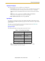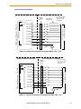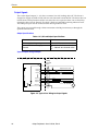
1
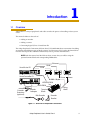
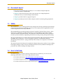
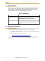
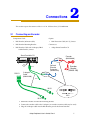
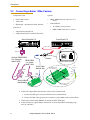
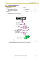
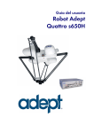
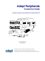
Adept Peripherals
Connection Guide
Common connections to SmartController CX and SmartVision EX
Ethernet
1394b
SmartVision EX
1394a
10
1
to I/O card
SmartController CX
Hirose
*S/N 3562-XXXXX*
SmartServo
OK
HPE
LAN
SF
ES
HD
1
2
3
1.1
SW1
1 2 3 4
1.2
IEEE-1394
2.1
Device Net
2.2
RS-232/TERM
Eth 10/100
BELT ENCODER
RS-232-2
RS-232-1
ON
OFF
XDIO
XUSR
XSYS
XFP
XMCP
XDC1 XDC2
24V
5A
-+
-+
HPDB50-DB50
}
DB50-DB50
Encoder
Extension
(optional)
Encoder
Y-adapter
Hirose
RJ45 - 10 pin
RS-422/485
SmartController CX
CAMERA
R
Terminal
Block
Belt Encoder
Flying
Leads
Encoder
Bracket
P/N: 09672-000, Rev. A
January, 2010
5960 Inglewood Drive • Pleasanton, CA 94588 • USA • Phone 925.245.3400 • Fax 925.960.0452
Otto-Hahn-Strasse 23 • 44227 Dortmund • Germany • Phone +49.231.75.89.40 • Fax +49.231.75.89.450
Block 5000 Ang Mo Kio Avenue 5 • #05-12 Techplace II • Singapore 569870 • Phone +65.6755 2258 • Fax +65.6755 0598
The information contained herein is the property of Adept Technology, Inc., and shall not be reproduced
in whole or in part without prior written approval of Adept Technology, Inc. The information herein is subject to change without notice and should not be construed as a commitment by Adept Technology, Inc. This
manual is periodically reviewed and revised.
Adept Technology, Inc., assumes no responsibility for any errors or omissions in this document. Critical
evaluation of this manual by the user is welcomed. Your comments assist us in preparation of future documentation. Please email your comments to: [email protected].
Copyright © 2010 by Adept Technology, Inc. All rights reserved.
Adept, the Adept logo, the Adept Technology logo, AdeptVision, AIM, Blox, Bloxview, FireBlox,
Fireview, HexSight, Meta Controls, MetaControls, Metawire, Soft Machines, and Visual Machines
are registered trademarks of Adept Technology, Inc.
Brain on Board is a registered trademark of Adept Technology, Inc. in Germany.
Adept ACE, ACE PackXpert, Adept 1060 / 1060+, Adept 1850 / 1850 XP, Adept 540 Adept 560, Adept
AnyFeeder, Adept Award, Adept C40, Adept C60, Adept CC, Adept Cobra 350, Adept Cobra 350 CR/ESD,
Adept Cobra 550, Adept 550 CleanRoom, Adept Cobra 600, Adept Cobra 800, Adept Cobra i600, Adept
Cobra i800, Adept Cobra PLC server, Adept Cobra PLC800, Adept Cobra s600, Adept Cobra s800, Adept
Cobra s800 Inverted, Adept Cobra s850, Adept Cobra Smart600, Adept Cobra Smart800, Adept DeskTop,
Adept FFE, Adept FlexFeeder 250, Adept IC, Adept iSight, Adept Impulse Feeder, Adept LineVision, Adept
MB-10 ServoKit, Adept MC, Adept MotionBlox-10, Adept MotionBlox-40L, Adept MotionBlox-40R, Adept
MV Adept MV-10, Adept MV-19, Adept MV4, Adept MV-5, Adept MV-8, Adept OC, Adept Python, Adept
Quattro s650, Adept Quattro s650H, Adept sDIO, Adept SmartAmp, Adept SmartAxis, Adept
SmartController CS, Adept SmartController CX, Adept SmartModule, Adept SmartMotion, Adept
SmartServo, Adept sMI6, Adept sSight, Adept Viper s650, Adept Viper s850, Adept Viper s1300, Adept
Viper s1700, AdeptCartesian, AdeptCast, AdeptForce, AdeptFTP, AdeptGEM, AdeptModules,
AdeptMotion, AdeptMotion Servo, AdeptMotion VME, AdeptNet, AdeptNFS, AdeptOne, AdeptOne-MV,
AdeptOne-XL, AdeptRAPID, AdeptSight, AdeptSix, AdeptSix 300, AdeptSix 300 CL, AdeptSix 300 CR,
AdeptSix 600, AdeptTCP/IP, AdeptThree, AdeptThree-MV, AdeptThree-XL, AdeptTwo, AdeptVision,
AVI AdeptVision, AGS AdeptVision GV, AdeptVision I, AdeptVision II, AdeptVision VME, AdeptVision
VXL, AdeptVision XGS, AdeptVision XGS II, AdeptWindows, AdeptWindows Controller, AdeptWindows
DDE, AdeptWindows Offline Editor, AdeptWindows PC, AIM Command Server, AIM Dispense, AIM
PCB, AIM VisionWare, A-Series, FlexFeedWare, HyperDrive, IO Blox, MicroV+, MotionBlox, MotionWare,
ObjectFinder, ObjectFinder 2000, PackOne, PalletWare, sAVI, S-Series, UltraOne, V, V+ and VisionTeach
are trademarks of Adept Technology, Inc.
Any trademarks from other companies used in this publication
are the property of those respective companies.
Printed in the United States of America
Introduction
Overview
Adept offers a variety of peripherals and cables to make the process of installing a robot system
easier.
This manual addresses the tasks of:
• Adding an encoder
• Adding a camera
• Connecting digital I/O to a SmartVision EX
The Adept Peripherals Connections fold-out sheet (P/N: 09672-010) shows connections for adding
an encoder, three different types of Basler cameras, and for using an I/O card in the SmartVision
EX. This manual provides additional information, such as pin-outs and limitations.
NOTE: Both this manual and the fold-out sheet assume that you will be using the
optional terminal block and corresponding DB50 cables.
Ethernet
1394b
SmartVision EX
1394a
10
1
to I/O card
SmartController CX
Hirose
*S/N 3562-XXXXX*
CAMERA
R
SmartServo
OK
HPE
LAN
SF
ES
HD
1
2
3
1.1
SW1
1 2 3 4
1.2
IEEE-1394
2.1
Device Net
2.2
RS-232/TERM
Eth 10/100
BELT ENCODER
RS-232-2
RS-232-1
ON
OFF
XDIO
XUSR
XSYS
XFP
XMCP
XDC1 XDC2
24V
5A
-+
-+
HPDB50-DB50
}
DB50-DB50
Encoder
Extension
(optional)
Encoder
Y-adapter
Hirose
RJ45 - 10 pin
RS-422/485
SmartController CX
1.1
1
Terminal
Block
Belt Encoder
Flying
Leads
Encoder
Bracket
Figure 1-1. Overview of Peripheral Connections
Adept Peripherals User’s Guide, Rev A
3
Introduction
Camera Connection Components
Off-the-shelf cables and connectors that are readily available, such as Ethernet and IEEE 1394
cables, are not listed.
Basler 1394a Camera
Components:
SmartVision EX
Basler 1394a Camera
10-pin RJ45 cable
Options:
10 m
DB50 terminal block
09449-100
09438-000
DB50M-DB50F cable
2m
09447-020
DB50M-DB50F cable
5m
09447-050
10 m
09450-100
Basler 1394b Camera and Basler GigE Camera
Components:
SmartVision EX
Basler Camera
12-pin Hirose cable
Options:
DB50 terminal block
09438-000
DB50M-DB50F cable
2m
09447-020
DB50M-DB50F cable
5m
09447-050
0.5 m
09439-000
Encoder Connection Components
Components:
SmartController CX
TR-1 Encoder (with wheel)
Encoder mounting bracket
Options:
09439-100
Encoder cable (Y-adapter)
3m
09443-000
Encoder extension cable
5m
09446-050
I/O Card Connection Components
Components:
SmartVision EX
PCIe I/O card
HPDB50-DB50 cable
Options:
2m
DB50 terminal block
DB50M-DB50F cable
4
09228-040
09448-020
09438-000
5m
Adept Peripherals User’s Guide, Rev A
09447-050
Document Layout
1.2
Document Layout
• This manual supplements the two-sided, 11 x 17 in. fold-out Adept Peripherals
Connections sheet, P/N 09672-010.
• Chapter 2 of this manual consists of the same content as the Adept Peripherals
Connections sheet, in standard Adept manual format.
• Chapter 3 provides details to support Chapter 2.
• Chapter 4 provides pinouts for cables and ports used for connecting Adept peripherals.
1.3
Safety
The installation and use of Adept products must comply with all safety instructions and warnings
in their respective manuals. Installation and use must also comply with all applicable local and
national requirements and safety standards.
We recommend that you read the American National Standard for Industrial Robot Systems - Safety
Requirements, published by the Robotic Industries Association (RIA) in conjunction with the
American National Standards Institute. The publication, ANSI/RIA R15.06, contains guidelines
for robot system installation, safeguarding, maintenance, testing, startup, and operator training.
We also recommend that you read the International Standard IEC 204 or the European Standard
EN 60204, Safety of Machinery – Electrical Equipment of Machines, and ISO 10218 (EN 775),
Manipulating Industrial Robots – Safety, particularly if the country of use requires a CE-certified
installation.
This manual assumes that the user has attended an Adept training course and has a basic working
knowledge of Adept systems. The user should provide the necessary additional training for all
personnel who will be working with Adept systems.
1.4
How to Get Help
For details on getting assistance with your Adept software or hardware, you can access the
following information sources on the Adept corporate website:
• For Contact information: http://www.adept.com/contact/americas
• For Product Support information: http://www.adept.com/support/service-and-support/main
• For further information about Adept Technology, Inc.: http://www.adept.com
Adept Peripherals User’s Guide, Rev A
5
Introduction
1.5
Related Manuals
This manual covers the connection of Adept Peripherals. There are additional manuals that cover
installation and use of the Adept SmartController and Adept SmartVision EX. The following
manuals (available on the Adept Document Library CD-ROM provided with each system)
provide information on advanced configuration and system specifications.
Table 1-1. Related Manuals
Manual Title
1.6
Description
Adept SmartVision EX
User’s Guide
Details the installation, configuration, and use of your Adept
SmartVision EX. The Adept SmartVision EX must be set up and
configured before using some of the peripherals.
Adept SmartController
User’s Guide
Details the installation, configuration, and use of your Adept
SmartController CX. The Adept SmartController CX must be set
up and configured before control programs will execute
properly.
Adept Document Library
The Adept Document Library (ADL) contains documentation for Adept products. You can access
the ADL either from the CD-ROM provided with each system, or on-line as follows:
• Select Support > Document Library from the menu bar on the Adept website Home page,
or
• Type the following URL into your web browser:
http://www.adept.com/Main/KE/DATA/adept_search.htm
To locate information on a specific topic, use the Document Library search engine on the ADL
Search page. To view a list of available document titles, select an option from one of the listed
product categories.
6
Adept Peripherals User’s Guide, Rev A
2
Connections
This section repeats the contents of the 11 x 17 in. fold-out sheet, P/N: 09672-010.
2.1
Connecting an Encoder
Components Used:
Option:
•
Belt Encoder (0.5 meter cable)
•
•
Belt Encoder Mounting Bracket
Connects to:
•
Belt Encoder Cable with Y-Adapter, DB15
to M12 Female, 3 meter
•
M12 Extension Cable (M - F), 5 meter
Adept SmartController CX
SmartController CX
Encoder
(09439-000)
*S/N 3562-XXXXX*
SmartServo
OK
HPE
LAN
SF
ES
HD
1
2
3
1.1
SW1
1 2 3 4
1.2
IEEE-1394
2.1
Device Net
2.2
RS-232/TERM
RS-422/485
Eth 10/100
BELT ENCODER
RS-232-2
RS-232-1
ON
OFF
XUSR
Belt
Encoder
Port
DB15 f
BELT ENC.
09443-000
XFP
XSYS
BELT ENC.
09443-000
XMCP
XDC1 XDC2
24V
5A
-+
-+
M12 - M12
f
m
Optional
Encoder
Extension
(09446-050)
DB15 f
Encoder
Bracket
(09439-100)
M12 - M12
Y-adapter
Cable
(09443-000)
1
XDIO
SmartController CX
CAMERA
R
m
f
2
1
M12 f
M12 f
m
2
f
M12
M12 f
1. Mount the encoder and encoder mounting bracket.
2. Connect the encoder cable to the Y-adapter (an encoder extension cable may be used).
3. Plug the Y-Adapter cable into the Belt Encoder port of the SmartController.
Adept Peripherals User’s Guide, Rev A
7
Connections
2.2
Connecting a Basler 1394a Camera
Components Used:
Options:
•
Basler 1394a camera
•
•
1394a cable
DB50 - DB50 Extension Cable (M - F), 5
meter
•
RJ45 10-pin - unterminated cable, 10 meter
•
Terminal Block
Connects to:
•
Adept SmartController CX
•
Adept SmartVision EX (1394a PCIe board)
•
16- 20 AWG wire, 0.3 meter
•
DB50 - DB50 Cable (M - F), 2 meter
SmartController CX
SmartVision EX
*S/N 3562-XXXXX*
SmartServo
OK
HPE
LAN
SF
ES
HD
1
2
3
1.1
SW1
1 2 3 4
1.2
IEEE-1394
2.1
2.2
Device Net
Eth 10/100
RS-232/TERM
BELT ENCODER
RS-422/485
RS-232-2
RS-232-1
ON
OFF
XDIO
XUSR
XSYS
XFP
XDC1 XDC2
XMCP
24V
5A
-+
-+
SmartController CX
CAMERA
R
1394a Port
1394a cable
XDIO Port
DB50 m
CAMERA I/O
09449-010
Optional DB50-DB50
5 m Extension
DB50-DB50
(09447-050)
2 m Cable
(09447-020)
RJ45
Camera
10
1
Basler 1394a Camera
RJ45 Cable
(09449-100)
DB50 m
from
Camera
wire from terminal
2 to terminal 47
flying
leads
flying
leads
DB50 f
DB50 f
green lead
to terminal 41
Terminal Block
(09438-000)
white/green lead
to terminal 1
1. Connect the 1394a cable from the camera to the 1394a port on the SmartVision EX.
2. Connect the 10-pin RJ45 cable from the camera to the terminal block.
a. Connect the RJ45 green wire to terminal 41 on the terminal block.
b. Connect the RJ45 white/green wire to terminal 1 (signal 1001) on the terminal block.
3. Connect the terminal block DB50 to the SmartController XDIO port.
4. Connect terminal 2 (signal 1001) to terminal 47 on the terminal block with light gauge
wire (16 - 20 AWG).
8
Adept Peripherals User’s Guide, Rev A
Connecting a Basler 1394b Camera
2.3
Connecting a Basler 1394b Camera
Components Used:
Options:
•
Basler 1394b camera
•
•
1394b cable
DB50 - DB50 Extension Cable (M - F), 5
meter
•
Hirose - unterminated cable, 10 meter
•
Terminal Block
Connects to:
•
Adept SmartController CX
•
Adept SmartVision EX (1394b PCIe board)
•
16 - 20 AWG wire, 0.3 meter
•
DB50 - DB50 Cable (M - F), 2 meter
SmartController CX
SmartVision EX
*S/N 3562-XXXXX*
SmartServo
OK
HPE
LAN
SF
ES
HD
1
2
3
1.1
SW1
1 2 3 4
1.2
IEEE-1394
2.1
Device Net
2.2
Eth 10/100
RS-232/TERM
BELT ENCODER
RS-422/485
RS-232-2
RS-232-1
ON
OFF
XDIO
XUSR
XSYS
XFP
XMCP
XDC1 XDC2
24V
5A
-+
-+
SmartController CX
CAMERA
R
1394b Ports
1394b Cable
DB50 m
Camera
Optional DB50-DB50
5 m Extension
(09447-050)
DB50-DB50
2 m Cable
(09447-020)
Hirose
Plug
Hirose Cable
(09450-100)
DB50 m
Basler 1394b Camera
wire from terminal
2 to terminal 47
from
Camera
flying
leads
DB50 f
flying
leads
DB50 f
pink lead
to terminal 41
Terminal Block
(09438-000)
black lead
to terminal 1
1. Connect the 1394b cable from the camera to the 1394b port on the SmartVision EX.
2. Connect the 12-pin Hirose cable from the camera to the terminal block.
a. Connect the Hirose pink wire to terminal 41 on the terminal block.
b. Connect the Hirose black wire to terminal 1 (signal 1001) on the terminal block.
3. Connect the terminal block DB50 to the SmartController XDIO port.
4. Connect terminal 2 (signal 1001) to terminal 47 on the terminal block with light gauge
wire (16 - 20 AWG).
Adept Peripherals User’s Guide, Rev A
9
Connections
2.4
Connecting a Basler GigE Camera
Components Used:
Options:
•
Basler GigE camera
•
DB50 - DB50 Extension Cable (M - F), 5 m
•
Ethernet cable
•
Terminal Block
•
Hirose - unterminated cable, 10 meter
Connects to:
•
Adept SmartController CX
•
Adept SmartVision EX (GigE PCIe board)
SmartController CX
•
16 - 20 AWG wire, 0.3 meter
•
DB50 - DB50 Cable (M - F), 2 meter
SmartVision EX
*S/N 3562-XXXXX*
SmartServo
OK
HPE
LAN
SF
ES
HD
1
2
3
1.1
SW1
1 2 3 4
1.2
IEEE-1394
2.1
2.2
Device Net
Eth 10/100
RS-232/TERM
BELT ENCODER
RS-422/485
RS-232-2
RS-232-1
ON
OFF
XDIO
XUSR
XSYS
XFP
XMCP
XDC1 XDC2
24V
5A
-+
-+
SmartController CX
CAMERA
R
GigE Port
XDIO Port
Ethernet
Cable
DB50 m
Camera
Optional DB50-DB50
5 m Extension
(09447-050)
DB50-DB50
2 m Cable
(09447-020)
Hirose
Plug
Basler GigE Camera
Hirose Cable
(09450-100)
DB50 m
from
Camera
wire from terminal
2 to terminal 47
flying
leads
flying
leads
DB50 f
DB50 f
white lead to
terminal 48
brown lead to terminal 42
Terminal Block
(09438-000)
pink lead to terminal 41
black lead to terminal 1
1. Connect the Ethernet cable from the camera to the GigE port on the SmartVision EX.
2. Connect the 12-pin Hirose cable from the camera to the terminal block.
a. Connect the Hirose pink wire to terminal 41 on the terminal block.
b. Connect the Hirose black wire to terminal 1 (signal 1001) on the terminal block.
c. Connect the Hirose brown wire to terminal 42 on the terminal block.
d. Connect the Hirose white wire to terminal 48 on the terminal block.
3. Connect the terminal block DB50 to the SmartController XDIO port.
4. Connect terminal 2 (signal 1001) to terminal 47 on the terminal block with light gauge
wire (16 - 20 AWG).
10
Adept Peripherals User’s Guide, Rev A
Connecting Digital I/O
2.5
Connecting Digital I/O
Components Used:
Options:
•
•
Terminal Block
•
DB50 - DB50 Extension Cable (M - F), 5
meter
DB50 - HPDB50 Cable, 2 meter
(supplied with the I/O board)
Connects to:
•
Adept SmartVision EX (I/O PCIe board)
SmartVision EX
HPDB50 m
(SCSI-2)
DB50-HPDB50
2 m Cable
(09448-020)
DB50 f DB50 m
Optional DB50-DB50
5 m Extension
(09447-050)
DB50 f
Terminal Block
(09438-000)
1. Connect the HPDB50 end of the 2-meter cable to the I/O card on the SmartVision EX.
2. Connect the DB50 end of the 2-meter cable to the terminal block.
Adept Peripherals User’s Guide, Rev A
11
Peripheral Connection Details
3
The fold-out sheet assumes the simplest installation for the items covered: one encoder only, use
of the first available signal for connections to the terminal block, etc.
This section elaborates a bit, to cover the next level of complexity that you might encounter if your
installation is a bit more complicated.
3.1
Encoders
Y-Adapter Cable
The Y-Adapter Cable can connect to two encoders.
One SmartController CX can process two belt encoders through the Belt Encoder jack.
Encoder Extension Cable
If you need to connect more than two encoder extension cables, contact Adept.
3.2
Cameras
Breakout Terminal Block
Although the terminal block is optional, the fold-out and this manual assume you will be using
one, along with its corresponding DB50 cables.
NOTE: For individual terminal connections, 16 - 20 AWG wire is recommended.
NOTE: Pin numbers on the terminal block match those on the XDIO port on the
SmartController and the PCIe I/O card on the SmartVision EX.
The terminal block is used to connect pins on the SmartController XDIO port and the SmartVision
EX I/O card to user data and power lines. Some Adept-supplied cables, such as the Hirose and
RJ45, have flying leads that connect to individual terminals on the terminal block.
All user connections are made with flying leads attached to individual terminals. See Table 4-3,
“XDIO Digital I/O Connector Pin Assignments,” on page 19 and Table 4-4, “I/O Card Pin
Assignments,” on page 20 for pinout information.
Adept Peripherals User’s Guide, Rev A
13
Peripheral Connection Details
SmartController CX Connections
The terminals you use on the terminal block will determine where the SmartController will find
the corresponding signals. For cameras, these are latch or strobe signals. These are covered in the
next section.
The Input Return for the Input Signal you use needs to be wired back to Ground on the terminal
block. If, for instance, you used Input Signal 1001, then you need to wire Input Return 1001 to
Ground. 16 - 20 AWG wire is recommended.
SmartController CX Latch Configuration
In addition to the physical wiring, the SmartController’s configuration must be set to read the
latch input signal.
This can be done from CONFIG_C or an Adept ACE-based utility program.
Edit the configuration file, and, in the ROBOT section, add the following line:
BELT 1 = “/POS_LATCH 1001”
This means that, when signal 1001 (Pins 1 and 2 on the XDIO connection) goes HIGH, the encoder
value of Belt Index 1 will be latched. If you wired one of the other signals, replace 1001 with the
appropriate signal number.
NOTE: The drawings in the fold-out use signal 1001. You can choose other signals,
and change the wiring and configuration, as needed. Refer to Table 4-3, “XDIO
Digital I/O Connector Pin Assignments,” on page 19 for other signal
connections.
This format is supported on the CX controller. There should be no other references to
“POS_LATCH xxxx” in any of the other config file sections.
NOTE: Do not use “POS_LATCH1”. This is for legacy systems, and is not
supported on the SmartController CX.
Camera Speed (throughput)
GigE
A standalone SmartVision EX (not connected to a SmartController or network) can have
up to four Ethernet ports: two are built-in, and two more are possible with two GigE
expansion cards. The SmartVision EX unit makes no distinction between the different
Ethernet ports. Four ports will support up to four cameras at the full GigE speed of 1000
Mbit/s each.
A SmartVision EX that is connected to a SmartController or network will have one built-in
Ethernet port available, and one more for each GigE expansion card in the unit.
If a switch is used to add more cameras, the 1000 Mbit/s will be shared between all
cameras being serviced by each port. Two cameras on one port can run at a maximum
speed of 500 Mbit/s each, and so on.
14
Adept Peripherals User’s Guide, Rev A
Cameras
1394b
Each 1394b expansion card has three ports. The total capacity of each card is 800 Mbit/s,
which is divided between the number of cameras using that card. The fastest throughput
per camera is obtained with one camera per card, yielding the full 800 Mbit/s for that
camera. Two cameras on one card can operate at 400 Mbit/s each, and so on.
Adding a second 1394b card adds another 800 Mbit/s of bandwidth, which will be
divided between the cameras connected to that card.
1394a
Each 1394a expansion card has two ports. The total capacity of each card is 400 Mbit/s,
which is divided between the number of cameras using that card. The fastest throughput
is obtained with one camera per card, yielding the full 400 Mbit/s for that camera. Two
cameras on one card can operate at a maximum speed of 200 Mbit/s each.
Adding a second 1394a card adds another 400 Mbit/s of bandwidth, which will be
divided between the cameras connected to that card.
Basler 1394a Camera
RJ45 cable pin assignments are listed in Table 4-2, “RJ45 Cable Pin Assignments,” on page 18.
Wire colors for non-Adept RJ45 cables may not match Adept cables.
NOTE: The RJ45 will not be needed for a 1394a camera if a conveyor is not used,
and the camera latch and strobe signals are not used.
NOTE: The RJ45 connector on the back of the Basler 1394a camera looks similar to
an Ethernet connector, but the RJ45 has 10 pins. A standard Ethernet connector
will not work for connecting to a Basler 1394a camera.
Basler 1394b Camera
The Hirose cable provides signal lines for latch and strobe. Hirose cable pin assignments are listed
in Table 4-1, “Hirose Cable Pin Assignments,” on page 17.
NOTE: The Hirose cable will not be needed for a 1394b camera if a conveyor is not
used, and the camera latch and strobe signals are not used.
Basler GigE Camera
NOTE: A GigE camera can be connected to any available Ethernet port on the
SmartVision EX.
24 VDC power, which is normally supplied to a GigE camera through the Hirose cable, can
instead be supplied by a suitable external power supply. The Adept SmartController User’s Guide
and Adept SmartVision EX User’s Guide give guidelines and sources for suitable power supplies.
The Hirose power pins can only reliably supply about 700 mA, so the configuration shown in the
fold-out would work for one or two GigE cameras (Basler specs the cameras at ~250 mA @ 24 V),
assuming that no other I/O is using some of this power. If more cameras are used, or additional
I/O power is used for other purposes, then an external power supply will be needed.
Adept Peripherals User’s Guide, Rev A
15
Peripheral Connection Details
3.3
SmartVision EX I/O Card
This manual is written assuming you will use a terminal block with the SmartVision EX I/O card.
It is also possible to use an HPDB50 cable with flying leads to access the I/O card, but Adept
recommends use of a terminal block for these connections.
16
Adept Peripherals User’s Guide, Rev A
Pinouts
4
This chapter shows pinouts for cables and ports used for connecting Adept peripherals.
4.1
Hirose 12-pin Cable
The Hirose cable is used to provide power for Basler GigE cameras, and to carry latch and strobe
signals for Basler GigE and 1394b cameras.
Table 4-1. Hirose Cable Pin Assignments
Pin
Color
Signal
Pin
Color
Signal
1
White
Camera Power GNDa
7
Violet
I/O Output 2
2
Green
Camera Power GND
8
Brown
Camera Power VCCb
3
Blue
I/O Input 1
9
Yellow
Camera Power VCC
4
Red
I/O Input 2
10
Pink
IO Output VCC
5
Gray
I/O Input GND
11
Gray/Pink
I/O Output 3
6
Black
I/O Output 1
12
Red/Blue
I/O Output 4
a
b
Pins 1 and 2 are tied together inside the camera.
Pins 8 and 9 are tied together inside the camera.
12
5
6
11
4
7
3
8
2
9
1
10
Figure 4-1. Back of Basler GigE Camera, with Hirose Pin Numbers
Adept Peripherals User’s Guide, Rev A
17
Pinouts
4.2
RJ45 10-pin Cable
The Basler 1394a camera uses an RJ45 10-pin cable to carry latch and strobe signals.
NOTE: The wire colors in the following table are for the Adept RJ45 cable only.
RJ45 cables purchased from other sources may have different wire colors.
Table 4-2. RJ45 Cable Pin Assignments
Pin
Wire Color
Signal
Pin
Wire Color
Signal
1
White/Grey
Output Port 3 -
6
White/Blue
In Gnd Comm
2
White/Orange
Output Port 2 -
7
Green
Out VCC Comm
3
Orange
Output Port 1 - (TrigRdy)
8
White/Brown
Input Port 2 +
4
White/Green
Output Port 0 - (IntEn)
9
Brown
Input Port 1 +
5
Blue
Input Port 0 +
10
Grey
Input Port 3 +
By default, Output Port 0 transmits a signal indicating when exposure has taken place.
10
6
5
4
3
2
1
1
Figure 4-2. Back of Basler 1394a Camera, with Pinouts
4.3
XDIO Connector
The XDIO connector on the SmartController is a 50-pin, standard-density D-Sub female connector.
There are 12 inputs and 8 outputs, each optically isolated from the circuitry of the
SmartController. The signals are numbered 1001 through 1012 for the inputs and 1 through 8 for
the outputs. Each channel has an input and a corresponding return line.
All the signals have independent source and ground connections. These inputs contain the four
high-speed inputs that are used by the system for interrupts and latching. The outputs, although
independent, have a lower current rating of 100 mA compared to 700 mA for the extended outputs
on the sDIO. See the V+ Language User’s Guide for information on digital I/O programming.
18
Adept Peripherals User’s Guide, Rev A
XDIO Connector
The connector also provides 24 V pins for powering customer equipment. There are four 24 V pins
and four ground pins, which are limited to a total of 1 A of current. The source of the 24 V is the
XDC connector on the front of the SmartController.
Table 4-3. XDIO Digital I/O Connector Pin Assignments
Pin
Signal
Pin
Signal
1
Input 1001
2
1001 return
3
Input 1002
4
1002 return
5
Input 1003
6
1003 return
7
Input 1004
8
1004 return
9
Input 1005
10
1005 return
11
Input 1006
12
1006 return
13
Input 1007
14
1007 return
15
Input 1008
16
1008 return
17
Input 1009
18
1009 return
19
Input 1010
20
1010 return
21
Input 1011
22
1011 return
23
Input 1012
24
1012 return
25
Output 0001+
26
Output 0001–
27
Output 0002+
28
Output 0002–
29
Output 0003+
30
Output 0003–
31
Output 0004+
32
Output 0004–
33
Output 0005+
34
Output 0005–
35
Output 0006+
36
Output 0006–
37
Output 0007+
38
Output 0007–
39
Output 0008+
40
Output 0008–
41
24 V Outputa
42
24 V Outputa
43
24 V Outputa
44
24 V Outputa
45
V+ High Power On Indicator +
46
V+ High Power On Indicator –
47
24 V return
48
24 V return
49
24 V return
50
24 V return
Pin 17
Pin 33
XDIO
Pin 50
a
Pin 1
Pin 18
Pin 34
Limited to combined total of 1 A of current.
Adept Peripherals User’s Guide, Rev A
19
Pinouts
4.4
PCIe I/O Card Connections
The I/O card on the SmartVision EX has a single port: a 50-pin, half-pitch D-Sub female
(HPDB50). There are 16 inputs and 16 outputs. The signals are numbered 1001 through 1016 for
the inputs and 1 through 16 for the outputs.
Table 4-4. I/O Card Pin Assignments
20
Pin
Signal
Pin
Signal
1
VDD Input (fly-wheel diode)
26
VDD Input (fly-wheel diode)
2-4
Common ground or common
power for inputs 1009 - 1016
27
Isolated power output
5 V (Do not use)
2829
Common ground or common
power for inputs 1009 - 1016
5
Output 8
30
Output 15
6
Output 7
31
Output 16
7
Output 6
32
Output 13
8
Output 5
33
Output 14
9
Output 4
34
Output 11
10
Output 3
35
Output 12
11
Output 2
36
Output 9
12
Output 1
37
Output 10
13
Input 1004 High
38
Input 1008 High
14
Input 1004 Low
39
Input 1008 Low
15
Input 1003 High
40
Input 1007 High
16
Input 1003 Low
41
Input 1007 Low
17
Input 1002 High
42
Input 1006 High
18
Input 1002 Low
43
Input 1006 Low
19
Input 1001 High
44
Input 1005 High
20
Input 1001 Low
45
Input 1005 Low
21
Input 1012
46
Input 1016
22
Input 1011
47
Input 1015
23
Input 1010
48
Input 1014
24
Input 1009
49
Input 1013
25
Output Gnd
50
Output Gnd
Pin 26
Pin 50
Pin 1
Pin 25
Adept Peripherals User’s Guide, Rev A
PCIe I/O Card Connections
Optional I/O Products
These optional products are also available for use with digital I/O:
• Terminal Block, with terminals for user wiring. Connects to the PCIe connector on the I/O
card in the SmartVision EX or the XDIO port on the SmartController CX. (09438-000)
This manual and the corresponding fold-out sheet assume you will be using a terminal
block.
NOTE: The I/O card is supplied with an HPDB50 - DB50 Cable (09448-020), 2
meters long, for connecting the I/O card to the terminal block.
• DB50 - DB50 Extension Cable, 5 meters long. (09447-050)
Input Signals
The 16 inputs are arranged in two groups. Inputs 1001 through 1008 are independently isolated
and differential. Inputs 1009 through 1016 are grouped into a bank, and all share a single common
source/sink line.
The inputs are accessed through direct connection to the 50-pin connector (see Table 4-4 on
page 20), or through the optional terminal block.
Input Specifications
The following table applies to all inputs, 1001 - 1016, on the I/O card.
Table 4-5. I/O Card Input Specifications
Operational voltage range
0 to 30 VDC
“OFF” state voltage range
0 to 3 VDC
“ON” state voltage range
10 to 30 VDC
Typical threshold voltage
Vin = 8 VDC
Operational current range
0 to 12.5 mA
“OFF” state current range
0 to 1.25 mA
“ON” state current range
4.2 to 12.5 mA
Typical threshold current
3.3 mA
Impedance (Vin/Iin)
2.4 KΩ minimum
NOTE: The input current specifications are provided for reference. Voltage
sources are typically used to drive the inputs.
Adept Peripherals User’s Guide, Rev A
21
Pinouts
In the following figure, Example 1 shows inputs 1001 to 1003 with a negative common, Example 2
shows inputs 1004 to 1006 with a positive common, and Example 3 shows inputs 1007 and 1008
with independent power supplies (no common).
NOTE: These are examples. Either method can be used on any channel.
Adept-Supplied Equipment
Customer-Supplied Equipment
(Typical Examples)
(equivalent circuit)
Connector on I/O Card - Differential Inputs
H 19
Input 1001
L 20
Input 1002
H 17
+
L 18
Example 1
+
–
Customer power
supply
H 15
Input 1003
L 16
H 13
Input 1004
Example 2
L 14
H 44
Input 1005
+
L 45
–
Customer power
supply
H 42
Input 1006
L 43
H 40
Input 1007
L 41
H 38
Input 1008
Example 3
+ –
L 39
+ –
Sourcing
Sinking
Figure 4-3. Differential Digital Inputs, 1001 through 1008
22
Adept Peripherals User’s Guide, Rev A
PCIe I/O Card Connections
Typical Input Wiring Example
User-Supplied Equipment
Adept-Supplied Equipment
Wiring
Terminal
Block
(equivalent circuit)
Input 1010
Input 1011
Input Bank
Input 1012
24
Part Present Sensor
23
Feeder Empty Sensor
22
Part Jammed Sensor
21
Sealant Ready Sensor
49
Input 1013
48
Input 1014
47
Input 1015
Bank configured for
Sinking (NPN) Inputs
50-Pin Input Connector - I/O Card
Input 1009
Note: all Input signals
can be used for either
sinking or sourcing
configurations.
Typical User
Input Signals
Input 1016 46
Input Comm
2, 3, 4, 28, 29
10 - 30 VDC
Supply
+
-
Figure 4-4. Typical User Wiring for Sinking Input Signals 1009 - 1016
Adept-Supplied Equipment
User-Supplied Equipment
Note: all Input signals
can be used for either
sinking or sourcing
configurations.
Wiring
Terminal
Block
(equivalent circuit)
Input 1010
Input Bank
Input 1011
Input 1012
Input 1013
Input 1014
Input 1015
Input 1016
Input Comm
24
23
22
Bank configured for
Sourcing (PNP) Inputs
50-Pin Input Connector – I/O Card
Input 1009
21
49
48
47
46
2, 3, 4, 28, 29
+
-
10 - 30 VDC
Supply
Figure 4-5. Typical User Wiring for Sourcing Input Signals 1009 - 1016
Adept Peripherals User’s Guide, Rev A
23
Pinouts
Output Signals
The sixteen digital outputs (1 - 16) share a common, low side (sinking) driver IC. The driver is
designed to supply any kind of load with one side connected to 10 to 30 VDC. The driver does not
include short-circuit protection and the user must take care to prevent shorts. An overload may
damage the driver circuit. Internal “fly-wheel” diodes are included for driving inductive loads.
The VDD power pin must be connected when driving inductive loads.
The outputs are accessed through a direct connection to the 50-pin connector, or through the
optional terminal block.
Output Specifications
Table 4-6. I/O Card Output Specifications
Parameter
Value
Power supply voltage range
10 to 30 VDC
Operational current range, per
channel
Iout ≤ 62.5 mA, all channels active
Iout ≤ 500 mA, one channel active
Typical Output Wiring Example
Adept-Supplied Equipment
VDD
Outputs 1 - 16
Output 1
Output 2
Output 3
Output 14
Output 15
Output 16
1, 26
User-Supplied Equipment
Wiring
Terminal
Block
Typical User Loads
12
11
10
33
30
Load
Load
31
Output Gnd 25, 50
Load
10 - 30 VDC
Figure 4-6. Typical User Wiring for Output Signals
24
Adept Peripherals User’s Guide, Rev A
+
-
P/N: 09672-000, Rev A
5960 Inglewood Drive
Pleasanton, CA 94588
925·245·3400