1
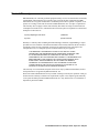
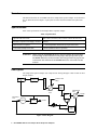
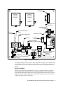
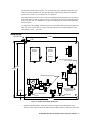
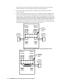
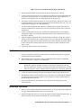
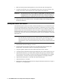
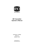
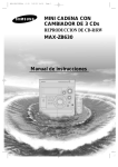
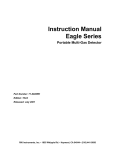
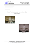
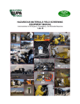
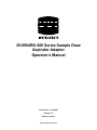
30-0954RK-200 Series Sample Draw
Aspirator Adapter
Operator’s Manual
Part Number: 71-0188RK
Revision: E
Released: 5/16/12
www.rkiinstruments.com
WARNING
Read and understand this instruction manual before operating
detector. Improper use of the detector could result in bodily harm
or death.
Periodic calibration and maintenance of the detector is essential
for proper operation and correct readings. Please calibrate and
maintain this detector regularly! Frequency of calibration
depends upon the type of use you have and the sensor types.
Typical calibration frequencies for most applications are between
3 and 6 months, but can be required more often or less often
based on your usage.
30-0954RK-200 Series Sample Draw Aspirator Adapter
Product Warranty
RKI Instruments, Inc. warrants gas alarm equipment sold by us to be free from defects in materials,
workmanship, and performance for a period of one year from the date of shipment from RKI
Instruments, Inc. Any parts found defective within that period will be repaired or replaced, at our
option, free of charge. Parts must be returned to RKI Instruments, Inc. for repair or replacement.
This warranty does not apply to those items which by their nature are subject to deterioration or
consumption in normal service, and which must be cleaned, repaired or replaced on a routine basis.
Examples of such items are:
a) Pump diaphragms and valves
c) Batteries
b) Fuses
d) Filter elements
Warranty is voided by abuse including mechanical damage, alteration, rough handling, or repair
procedures not in accordance with instruction manual. This warranty indicates the full extend of
our liability, and we are not responsible for removal or replacement costs, local repair costs,
transportation costs, or contingent expenses incurred without our prior approval.
THIS WARRANTY IS EXPRESSLY IN LIEU OF ANY AND ALL OTHER
WARRANTIES AND REPRESENTATIONS, EXPRESSED OR IMPLIED, AND
ALL OTHER OBLIGATIONS OR LIABILITIES ON THE PART OF RKI
INSTRUMENTS, INC. INCLUDING BUT NOT LIMITED TO, THE WARRANTY OF
MERCHANTABILITY OR FITNESS FOR A PARTICULAR PURPOSE. IN NO
EVENT SHALL RKI INSTRUMENTS, INC. BE LIABLE FOR INDIRECT,
INCIDENTAL OR CONSEQUENTIAL LOSS OR DAMAGE OF ANY KIND
CONNECTED WITH THE USE OF ITS PRODUCTS OR FAILURE OF ITS
PRODUCTS TO FUNCTION OR OPERATE PROPERLY.
This warranty covers instruments and parts sold to users only by authorized distributors, dealers
and representatives as appointed by RKI Instruments, Inc.
We do not assume indemnification for any accident or damage caused by the operation of this gas
monitor and our warranty is limited to the replacement of parts or our complete goods. Warranty
covers parts and labor performed at RKI Instruments, Inc. only, and does not cover field labor or
shipment of parts back to RKI.
30-0954RK-200 Series Sample Draw Aspirator Adapter
Overview
This manual describes the 30-0954RK-200 Series sample draw aspirator adapter. It also describes
how to install and use the adapter. A spare parts list at the end of this manual lists replacement
parts.
Specifications
Table 1 lists specifications for the Sample Draw Aspirator Adapter.
Table 1: Specifications
Applicable Detector Heads
RKI S Series, S2 Series, M2, or direct connect detector head
Maximum Compressed Air Supply Pressure
140 PSI
Outlet Pressure to Aspirator
5 - 50 PSI adjustable (determined by required flow rate)
Recommended Sample Flow Rate
3 SCFH (standard cubic feet per hour)
WARNING: When using the 30-0954RK-200 Series, you must follow the instructions
and warnings in this manual to assure proper and safe operation of the
30-0954RK-200 Series and to minimize the risk of personal injury. Be sure
to maintain and calibrate the 30-0954RK-200 Series as described in this
manual.
Description
The sample draw aspirator adapter uses compressed air flowing through a venturi to draw air into a
sample chamber.
Detector
Head 2
(optional)
Calibration Gas
Fitting
Flow Meter
Detector
Head 1
Flow
Fail
Switch
Inlet/Blowback
Valve
Calibration
Valve
Sample
Filter
Compressed
Air In
Regulator
Aspirator
Exhaust
Restrictor
V
(Vaccum
Port)
Figure 1: Flow Diagram
1 • 30-0954RK-200 Series Sample Draw Aspirator Adapter
Drain
Fault
Switch
Flow Meter
Detector
Head with
Chamber
Detector
Head with
Chamber
1
2
IN
(optional)
IN
Calibration Valve
Push Button
OUT
OUT
Calibration
Valve
Pressure Adjustment
Knob
Pressure
Gauge
Pressure Regulator
Aspirator
Calibration Fitting
Drain
Fault
Switch
Low Flow
Switch
Aspirator/Sample
Exhaust (1/8 NPT female)
Adjustment
Screw
-
+
Inlet/Blowback
Valve
Low Flow and Drain
Fault Contact
Housing
Water Trap
Inlet/Blowback Valve Button
1/4 O.D. Tube Compressed Air
Inlet Fitting
1/4 O.D. Tube Sample Inlet Fitting
Figure 2: Component Location
The sample draw adapter consists of eleven major components (see Figure 2 ): the detector head (1
or 2), regulator, aspirator, detector adapter, detector chamber (1 or 2), flowmeter, calibration valve,
inlet/blowback valve, low flow switch, drain fault switch, and low flow and drain fault contact
housing.
Detector Head(s)
Each detector head provides a signal that can be used by a controller to indicate the sample gas
level. Any RKI S Series, S2 Series, M2, or direct connect detector head can be used with the
sample drawing adapter plate. Figure 2 above shows the approximate location of the two detector
heads. Please see the detector head operator’s manual of the detector head(s) in your system for a
complete description of the detector head(s).
30-0954RK-200 Series Sample Draw Aspirator Adapter • 2
Regulator
The regulator has an inlet port on its left side with a 1/4” tube fitting. The maximum allowable inlet
pressure is 140 PSI. A gauge at the bottom of the regulator indicates the output pressure. The output
pressure, and detector flow, can be adjusted using the knob on the front of the regulator. The
detector flow rises or falls as the output pressure is increased or decreased.
Aspirator
The aspirator inlet is connected to the output port on the right side of the regulator and the vacuum
port on top is connected to the detector chamber. It has a venturi tube inside it which generates a
vacuum at its top port when compressed air flows through it. The compressed air and the air drawn
from the detector chamber into the top port of the aspirator both exhaust at the right side of the
aspirator.
Detector Adapter
The detector adapter screws directly onto the detector. It is installed hand tight. It has a gasket
inside it which seals against the detector. When removing this adapter to change the detector, be
sure not to lose this gasket. Each specific sensor requires its own detector adapter.
Detector Chamber
The chamber has three thumbscrews which fasten it to the detector adapter. An O-ring at the top of
the chamber seals the chamber/adapter interface. The inlet of the chamber is on the side and is
connected to the exhaust of the flowmeter. The exhaust of the chamber is at the bottom and is
connected to the vacuum port of the aspirator.
Flowmeter
The flowmeter indicates the flow to the detector(s). It has a 1/4” OD tube fitting at its inlet and
exhaust port. The exhaust port of the flow meter is connected to the detector chamber or to the first
detector chamber if two detector heads are installed. The flowmeter’s indication range is 1 - 10
SCFH. It has no flow adjustment valve because the flowrate is controlled by the regulator setting.
Calibration Valve
The calibration valve is a manual operation spring return valve with a push button actuator. This
valve is used to switch from sample flow to calibration gas during the calibration process. When
the button is pushed and held, the sample port is closed and the calibration port is opened.
Inlet/Blowback Valve
The inlet/blowback valve is a manual operation spring return valve. A push button actuator is
located on the front of the valve. This valve is used to switch from sample flow to blow back in the
event of a clogged sample line. When the push button is pressed and held, the valve diverts the
compressed air supply back through the sample line to clear obstructions.
WARNING:
The blowback pressure can be as high as 140 PSI. Make sure that all personnel
and equipment are clear of the sample line inlet end to avoid personal injury or
equipment damage if a sample line obstruction is blown out of the sample line.
Low Flow/Drain Fault Contact Housing
The low flow switch provides open contacts in normal operation in the low flow/drain fault contact
housing that close in the event of a low flow condition. Two contact wires protrude from the side of
the switch and enter the low flow contact housing through a plastic cable bushing on the left side of
the housing. Terminals are provided in the low flow/drain fault contact housing for field connection
to the switch contacts.
3 • 30-0954RK-200 Series Sample Draw Aspirator Adapter
The drain fault switch senses a break or very low flow in the water drain line and provides open
contacts in normal operation in the low flow/drain fault contact housing which close when the
switch senses a break, a very low drain flow, or a shut down.
Connecting monitoring devices to the low flow and drain fault contact terminals provides the user
with a notification of a contact closure. Each set of contacts may have their own monitoring device
or they may share one. See “Installation” on page 4 for instructions to wire these terminals using
the two scenarios.
A second plastic cable bushing on the bottom of the low flow/drain fault contact housing allows for
cable entry to the housing. The size range of the cable which can be routed through the second
cable bushing is .064’’ - .210’’ OD.
Installation
(4X) Ø 0.50
19.25
0.75
Detector
Head with
Chamber
Detector
Head with
Chamber
1
2
(optional)
IN
IN
Low Flow and Drain Fault
Contact Housing
OUT
OUT
19.25
20.75
Aspirator/Sample Exhaust
-
+
Field Wiring Cable
Entry Bushing for
Switch Contact
0.75
140 PSI Compressed
Air Inlet
Sample Inlet
20.75
Figure 3: Outline & Mounting Dimensions
1.
Install the mounting panel to a flat vertical surface using the four mounting holes (0.50’’
diameter) in the corners of the panel. Make sure that sufficient space is allowed to remove the
30-0954RK-200 Series Sample Draw Aspirator Adapter • 4
detector head’s cover, and to bring power/signal wiring to the detector head. Also provide
sufficient clearance for routing of sample, compressed air, and exhaust lines.
2.
Connect power/signal wiring to the detector head(s) as described in the detector head
operator’s manual.
3.
Connect a contact monitoring device to the low flow and drain fault contact terminals inside
the low flow and drain fault contact housing using the field wiring cable entry bushing. The
contacts may be wired individually or in parallel. When wired individually, you will need one
monitoring device for each set of contacts. When a specific monitoring device goes into alarm,
you will immediately know which set of contacts closed and what the problem is. When wired
in parallel, only one monitoring device is needed to monitor both sets of contacts. However,
when that device goes into alarm, it will be unclear which set of contacts closed without further
investigation. Wiring diagrams for each scenario are shown below.
Contact
Monitoring
Device
Drain
Fault
Contact
Terminal
Block
Yellow
Yellow
Factory
Wired
Blue
Blue
Factory
Wired
Contact
Monitoring
Device
Low
Flow
Figure 4: Low Flow and Drain Fault Wiring, Independent Wiring
Drain
Fault
Yellow
Factory
Wired
Yellow
Blue
Blue
Factory
Wired
Low
Flow
5 • 30-0954RK-200 Series Sample Draw Aspirator Adapter
Contact
Terminal
Block
Contact
Monitoring
Device
Figure 5: Low Flow and Drain Fault Wiring, Parallel Wiring
4.
Start up the detector head(s) as described in the detector head operator’s manual.
5.
Connect a sample line from the area to be sampled to the sample inlet fitting at the bottom right
of the panel. The fitting accepts 1/4” OD rigid metal tubing such as copper, aluminum, or
stainless steel tubing. Be sure to use tubing appropriate for the target gas.
6.
The aspirator exhaust includes the sample air. It may be routed to a different area where it can
be exhausted safely by running tubing from the aspirator exhaust fitting to the “safe” area. The
aspirator exhaust fitting is a 1/4’’ OD tubing fitting.
7.
Turn the regulator adjustment knob completely counterclockwise and then turn it one turn
clockwise so that the flow will start out at a low level when the compressed air is connected
and turned on.
8.
Connect a compressed air source up to a maximum of 140 PSI to the inlet of the regulator.
Although the regulator is rated up to 300 PSI inlet pressure, other components are rated to a
maximum of 140 PSI.
9.
Adjust the regulator adjustment knob so that the flowmeter indicates 3 SCFH. The regulator
exhaust pressure indicated by the regulator gauge will vary for a particular flow depending on
the length of the sample line and other restrictions such as filters. Typically the pressure will be
between 5 and 10 PSI for short sample runs. It will be higher for longer sample runs and if
filters are used.
10. Calibrate the detector head(s) as described below.
Calibration
1.
Follow the instructions in the detector head operator’s manual for setting the zero (fresh air)
reading and making span adjustments.
2.
When introducing gas to the detector, fill a gas sample bag with a regulator or dispensing
valve. See “Parts List” on page 8 for available parts.
NOTE:
A gas bag is recommended for calibration instead of a demand flow regulator because a
demand flow regulator introduces enough flow restriction to significantly reduce the
flow. If a demand flow regulator is used, the flow will have to be adjusted up to 3 SCFH
while the regulator is connected during calibration and down to 3 SCFH after calibration.
3.
Connect the sample bag tubing to the hose barb calibration fitting on the calibration valve.
4.
Push and hold the button on the calibration valve to start the flow of gas through the calibration
gas fitting. Allow the sample draw adapter to draw sample for 2 minutes and then make any
calibration adjustments necessary.
5.
Release the push button on the calibration valve. Disconnect the sample bag from the
calibration fitting.
Blowback Operation
1.
In the event of a clogged sample line, the blowback valve can be used to divert the compressed
air supply back through the sample line to clear obstructions.
2.
Inspect the sample line first to try to remedy the situation without using the blowback valve. If
the line cannot be cleared, operate the blowback valve as described below.
30-0954RK-200 Series Sample Draw Aspirator Adapter • 6
3.
Make sure that all personnel and equipment are clear of the inlet end of the sample line.
4.
To operate the blowback valve, press and hold the button on the front of the blowback valve.
As long as the button is held, compressed air will be applied to the sample line.
WARNING:
5.
The blowback pressure can be as high as 140 PSI. Make sure that all personnel
and equipment are clear of the sample line inlet end to avoid personal injury or
equipment damage if a sample line obstruction is blown out of the sample line.
Release the button on the blowback valve. Verify that the sample is now flowing properly
through the sample line.
Setting the Drain Fault Switch
The drain fault switch is factory set to detect a break in the drain line or very low drain flow from
the water trap during operation. Under normal circumstances, it should not be necessary to adjust
the drain fault switch in the field. If the drain fault switch contacts close to indicate a problem in the
drain line and no cause can be determined, it may be necessary to adjust the drain fault switch. If
the drain fault switch contacts are not operating properly, perform the following procedure to set
the drain fault switch. If the drain fault switch contacts continue to operate improperly, contact RKI
Instruments, Inc.
NOTE: In order to get an accurate open/close reading on the drain fault switch contacts, the low
flow and drain fault switches must not be wired in parallel. Any monitoring device must
also be disconnected from the drain fault switch contacts. Remove any jumpers and
monitoring device wires from the drain fault switch contacts before setting the drain fault
switch.
1.
Ensure that the flowmeter reading is 3.0 SCFH.
2.
Open the enclosure and connect an ohm meter to the drain fault switch terminals on the
terminal block. Check that the contacts are open during normal operation.
3.
Using the regulator, adjust the flow down until the flowmeter reads 1.0 SCFH.
4.
Carefully adjust the drain fault switch using the adjustment screw until the contacts just close.
5.
Adjust the flow back above 1.0 SCFH with the regulator and repeat step 3 until the contacts
close between 0.8 and 1.0 SCFH. To increase the setpoint, turn the adjustment screw slightly
counterclockwise. To decrease the setpoint, turn the adjustment screw slightly clockwise.
6.
Adjust the flow back up above 1.0 SCFH. The contacts should reopen.
7.
Adjust the flowrate to 3.0 SCFH.
8.
Reconnect any wires that were removed before setting the drain fault switch. Refer to Figure 4
and Figure 5 for wiring diagrams.
7 • 30-0954RK-200 Series Sample Draw Aspirator Adapter
Parts List
Table 2 lists replacement parts and accessories for the sample draw adapter.
Table 2: Parts List
Part Number
Description
06-1248RK-03
Tubing, 3/16 x 5/16, polyurethane, 3 foot length, for calibration kit
07-0107RK
Gasket for 1/2 NPT type detector adapter
07-7120RK
O-ring for replaceable sensor type detector
07-7218RK
O-ring, 0.734 ID x 0.139, for 3/4 NPT type detector
07-7225RK
O-ring, 1.243 ID x .139, buna, for detector chamber
13-1070RK
Captive panel screw, 10-32 x 1.75
33-0413RK-02
Filter element for water trap
33-0413RK-10
Water trap
81-1001RK
Dispensing valve, for 34 liter steel cylinders
81-1051RK-60
Regulator with gauge and knob, 6 LPM, for 34 liter aluminum cylinder,
58 liter aluminum or steel, and 103 liter aluminum or steel cylinder
81-1127RK
Gas bag with fittings and hosebarb, 12 inches x 12 inches, 5 liters, tedlar
30-0954RK-200 Series Sample Draw Aspirator Adapter • 8