1
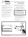
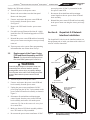
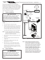
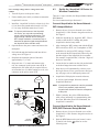
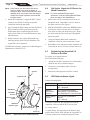
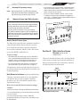
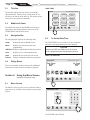
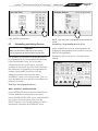
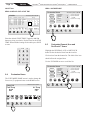
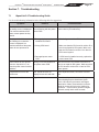
INSTALLATION MANUAL
iAquaLink™ 2.0
Web Connect Device
For use with the following Systems:
AquaLink® RS Systems: Rev R Firmware or later
AquaLink PDA Systems: Rev 6.0 Firmware or later
AquaLink Z4 Systems: All Firmware versions
WARNING
FOR YOUR SAFETY - This product must be installed and serviced by a contractor who is licensed and qualified in
pool equipment by the jurisdiction in which the product will be installed where such state or local requirements exist.
The maintainer must be a professional with sufficient experience in pool equipment installation and maintenance so
that all of the instructions in this manual can be followed exactly. Before installing this product, read and follow all
warning notices and instructions that accompany this product. Failure to follow warning notices and instructions
may result in property damage, personal injury, or death. Improper installation and/or operation will void the warranty.
Improper installation and/or operation can create unwanted electrical hazard which can cause serious injury, property
damage, or death.
ATTENTION
This device complies with part 15 of the FCC Rules. Operation is subject to the following two conditions: (1) This
device may not cause harmful interference, and (2) this device must accept any interference received, including
interference that may cause undesired operation.
NOTE: This equipment has been tested and found to comply with the limits for a Class B digital device, pursuant to
part 15 of the FCC Rules. These limits are designed to provide reasonable protection against harmful interference in
a residential installation. This equipment generates, uses and can radiate radio frequency energy and, if not installed
and used in accordance with the instructions, may cause harmful interference to radio communications. However,
there is no guarantee that interference will not occur in a particular installation. If this equipment does cause harmful
interference to radio or television reception, which can be determined by turning the equipment off and on, the user
is encouraged to try to correct the interference by one or more of the following measures:
• Reorient or relocate the receiving antenna.
• Increase the separation between the equipment and receiver.
H0435500 Rev B
• Connect the equipment to an electrical source on a circuit different from that to which the receiver is connected.
• Consult the dealer or an experienced radio/TV technician for help.
Modifications made to this equipment, which are not authorized by the manufacturer, may void the user’s authority
to operate this equipment.
iAquaLink™ 2.0 Web Connect Device for AquaLink® Control Systems | Installation Manual
ENGLISH
Page 3
Table of Contents
NOTE Some of the features described in this Manual DO NOT apply to all AquaLink models.
Section 1. Important Safety Instructions......... 4
Section 2. Overview of the iAquaLink 2.0 Web
Connect Device................................ 6
2.1
AquaLink 2.0 Requirements...............................6
Section 3. iAquaLink 2.0 Upgrade................. 6
3.1
3.2
Replacement of the CPU Board.........................6
Replacement of the Power Center PCB and
Bezel Assembly and CPU Board.......................7
Section 4. iAquaLink Network Interface
Installation........................................ 7
4.1
4.2
4.3
4.4
4.5
4.6
4.7
4.8
Outdoor Installation............................................8
Indoor Installation...............................................8
Set Up the iAquaLink 2.0 Device for Wireless
Connection.........................................................9
Set Up the iAquaLink 2.0 Device for Wired
Connection.......................................................10
Registering the iAquaLink 2.0 Device on
the web............................................................10
LED Status Indicator Lights.............................10
Account and Location Setup............................ 11
iAquaLink Apps and Web Interface.................. 11
Section 5. Web Interface Home Screen..........11
5.1
5.2
5.3
5.4
Title Bar............................................................12
Middle Info Panel.............................................12
Navigation Bar.................................................12
Dialog Boxes....................................................12
Section 6. Using the Menu Screen................. 12
6.1
Menu Screen....................................................12
6.2
To Set Up Date/Time........................................12
6.3
Scheduling and Adding Devices......................13
6.4
Customize Home.............................................14
6.5
Customize General, Aux and OneTouch™
Items................................................................14
Section 7. Troubleshooting............................ 15
7.1
iAquaLink 2.0 Troubleshooting Guide..............15
EQUIPMENT INFORMATION RECORD
DATE OF INSTALLATION
INSTALLER INFORMATION
INITIAL PRESSURE GAUGE READING (WITH CLEAN FILTER)
PUMP MODEL
HORSEPOWER
FILTER MODEL
SERIAL NUMBER
CONTROL PANEL MODEL
SERIAL NUMBER
NOTES:
Page 4
ENGLISH
iAquaLink™ 2.0 Web Connect Device for AquaLink® Control Systems | Installation Manual
Section 1. Important Safety Instructions
READ AND FOLLOW ALL INSTRUCTIONS
All electrical work must be performed by a licensed electrician and conform to all national, state, and local codes.
When installing and using this electrical equipment, basic safety precautions should always be followed, including the
following:
DANGER
To reduce the risk of injury, do not remove the suction fittings of your spa or hot tub. Never operate a spa or hot
tub if the suction fittings are broken or missing. Never replace a suction fitting with one rated less than the flow rate
marked on the equipment assembly.
WARNING
Prolonged immersion in hot water may induce hyperthermia. Hyperthermia occurs when the internal temperature
of the body reaches a level several degrees above the normal body temperature of 98.6°F (37°C). The symptoms
of hyperthermia include dizziness, fainting, drowsiness, lethargy, and an increase in the internal temperature of
the body. The effects of hyperthermia include: 1) unawareness of impending danger; 2) failure to perceive heat;
3) failure to recognize the need to exit spa; 4) physical inability to exit spa; 5) fetal damage in pregnant women; 6)
unconsciousness resulting in a danger of drowning.
WARNING
To Reduce the Risk of Injury a) The water in a spa should never exceed 104°F (40°C). Water temperatures between 100°F (38°C) and 104°F
(40°C) are considered safe for a healthy adult. Lower water temperatures are recommended for young children
and when spa use exceeds 10 minutes.
b) Since excessive water temperatures have a high potential for causing fetal damage during the early months
of pregnancy, pregnant or possibly pregnant women should consult a physician before using a spa or hot tub,
and should limit spa water temperatures to 100°F (38°C). Water temperature in excess of 38ºC (100ºF) may
be injurious to your health.
c) Before entering a spa or hot tub, the user should measure the water temperature with an accurate
thermometer since the tolerance of water temperature-regulating devices varies.
d) The use of alcohol, drugs, or medication before or during spa or hot tub use may lead to unconsciousness with
the possibility of drowning.
e) Obese persons and persons with a history of heart disease, low or high blood pressure, circulatory system
problems, or diabetes should consult a physician before using a spa.
f) Persons using medication should consult a physician before using a spa or hot tub since some medication
may induce drowsines while other medication may affect heart rate, blood pressure, and circulation.
WARNING
Risk of electric shock - Install the power center at least five (5) feet (1.52m) from the inside wall of the pool and/
or hot tub using non-metallic plumbing. Canadian installations must be at least three (3) meters from the water.
Children should not use spas or hot tubs without adult supervision.
Do not use spas or hot tubs unless all suction guards are installed to prevent body and hair entrapment.
People using medications and/or having an adverse medical history should consult a physician before using a spa
or hot tub.
iAquaLink™ 2.0 Web Connect Device AquaLink® Control Systems | Installation Manual
ENGLISH
Page 5
WARNING
People with infectious diseases should not use a spa or hot tub.
To avoid injury, exercise care when entering or exiting the spa or hot tub.
Do not use drugs or alcohol before or during the use of a spa or hot tub to avoid unconsciousness and possible
drowning.
Do not use a spa or hot tub immediately following strenuous exercise.
Prolonged immersion in a spa or hot tub may be injurious to your health.
Do not permit any electric appliance (such as a light, telephone, radio, or television) within 5 feet (1.52m) of a spa
or hot tub.
The use of alcohol, drugs or medication can greatly increase the risk of fatal hyperthermia in hot tubs and spas.
WARNING
To avoid injury ensure that you use this control system to control only packaged pool/spa heaters which have builtin operating and high limit controls to limit water temperature for pool/spa applications. This device should not be
relied upon as a safety limit control.
WARNING
A terminal bar marked "GROUND" is provided within the power center. To reduce the risk of electrical shock which
can cause serious injury or death, connect this terminal bar to the grounding terminal of your electric service or
supply panel with a continuous copper conductor having green insulation and one that is equivalent in size to the
circuit conductors supplying this equipment, but no smaller than no. 12 AWG (3.3mm2). In addition, a second wire
connector should be bonded with a no. 8 AWG (8.4mm2) copper wire to any metal ladders, water pipes, or other
metal within five (5) feet (1.52 m) of the pool/spa. In Canada the bonding wire must be minimum 6 AWG (13,3mm2).
CAUTION
A ground-fault circuit-interrupter must be provided if this device is used to control underwater lighting fixtures. The
conductors on the load side of the ground-fault circuit-interrupter shall not occupy conduit, boxes, or enclosures
containing other conductors unless the additional conductors are also protected by a ground-fault circuit-interrupter.
Refer to local codes for complete details.
Attention installer: Install to provide drainage of compartment for electrical components.
SAVE THESE INSTRUCTIONS
Page 6
ENGLISH
iAquaLink™ 2.0 Web Connect Device for AquaLink® Control Systems | Installation Manual
Section 2. Overview of the
iAquaLink 2.0 Web
Connect Device
Section 3. AquaLink RS and PDA
Hardware Upgrades
Welcome, and thank you for purchasing the iAquaLink
2.0 Web Connect Device!
The iAquaLink 2.0 Web Connect Device connects an
AquaLink System to the Internet through your existing
residential internet service.
This document gives instructions for installing the
iAquaLink 2.0 Web Connect Device. The instructions
must be followed exactly. Read through the instructions
completely before operating the equipment.
2.1
AquaLink 2.0 Requirements
The iAquaLink 2.0 Web Connect Device requires
compatible firmware as shown below:
AquaLink RS - requires revision R or newer.
AquaLink PDA - requires revision 6.0 or newer
AquaLink Z4 - all revisions will work
This section applies to older AquaLink systems. For
AquaLink RS rev R or later, or AquaLink PDA rev 6.0
or later, skip to section 4 of this manual.
3.1
Replacement of the CPU Board
This step is for the AquaLink RS with revision N
firmware or newer ONLY. For AquaLink PDA systems,
please go to section 3.2.
WARNING
Potentially high voltages in the power center can
create dangerous electrical hazards, possibly
causing death, serious injury or property damage.
Turn off power at the main circuit feeding the power
center to disconnect the power center from the
system.
Before or immediately after replacing the CPU board
the memory must be cleared as follows:
1. Write down current equipment programming, aux
labels and JVA assignments prior to clearing the
memory (This will be used in step 10)
2. Go into the System Setup.
3. Select CLEAR MEMORY and follow the prompts
to clear the memory.
Internet
iAquaLink
Thu June 23, 2011 3:03 PM
Pool Temp
Air Temp
86º
FILTER
PUMP
Home
SPA
Menu
78º
POOL
HEAT
SPA
HEAT
AUX1
AUX2
OneTouch
Help
Back
Status
AUX3
Other
Devices
On/Off
iAquaLink Home Screen
Router
Internet Service
Provider
Computer
Wireless
or
Wired Connection
iAquaLink 2.0
Device
Power Center
Figure 1.
iAquaLink 2.0 Web Connect Device
ENGLISH
iAquaLink™ 2.0 Web Connect Device for AquaLink® Control Systems | Installation Manual
Replace the CPU board as follows:
4. Turn off all power to the power center.
5. Remove the screws that secure the front panel.
Remove the front panel.
6. Unscrew and remove the power center PCB and
bezel assembly from the power center.
See Figure 2.
7. Remove the CPU board from the power center
PCB.
Page 7
power plug to the 24 VAC 3-pin terminal on the
new power center PCB.
7. Re-connect all terminal bars and input/output
control signals to the new power center PCB and
bezel assembly.
8. Reinstall the power center PCB and bezel assembly
in the power center can using the screws previously
removed.
8. For an RS system (Firmware Revision N - QQQ),
install the new CPU board and upgrade to revision
R or later.
Section 4. iAquaLink 2.0 Network
Interface Installation
9. Reinstall the power center PCB and bezel assembly
in the power center can using the screws previously
removed.
The iAquaLink 2.0 device can be installed outdoors, on
the equipment pad, or inside your home with a choice of
wired or wireless connection.
10. Turn on power to the system. Enter programming
information that was written down in step 1.
3.2
Power Center Transformer
24 VAC Power Plug
Replacement of the Power Center
PCB and Bezel Assembly and CPU
Board. (For AquaLink RS Systems prior to
Rev N and PDA systems prior to Rev 6.0)
WARNING
Power Center Can
Potentially high voltages in the power center can
create dangerous electrical hazards, possibly
causing death, serious injury or property damage.
Turn off power at the main circuit feeding the power
center to disconnect the power center from the
system.
Remove old PCB
1. Turn off all power to the power center.
2. Unscrew and remove the power center PCB and
bezel assembly from the power center.
3. Unplug the power center transformer 24 VAC
power plug from the 24 VAC 3-pin terminal on the
power center PCB and bezel assembly as shown in
Figure 2.
4. Disconnect all terminal bars and input/output
control signals from the power center PCB and
bezel assembly and remove it from the power
center can. Tip: Do not disconnect the wires from
the terminal bars.
J2 Connector,
24 VAC 3-Pin Terminal
Power Center PCB and
Bezel assembly
(Rear View)
24V
AC
J24
Install new PCB
CPU Board
5. Make sure the new PCB bezel assembly with the
new CPU board are fully assembled.
6. Re-connect the power center transformer 24 VAC
Figure 2.
Replacement of Power Center PCB and the
CPU Board Assembly
Page 8
ENGLISH
iAquaLink™ 2.0 Web Connect Device for AquaLink® Control Systems | Installation Manual
The wireless iAquaLink 2.0 device will transmit
through walls and around corners. The transceivers do
not require line of sight to communicate. Steel framing,
aluminum siding, wrought iron, cyclone fences, leaded
glass, and other 2.4 GHz frequency items may inhibit/
prevent communication between the iAquaLink 2.0
J-Box and the WiFi Access Point.
4.1
Internet
Router
Internet Service
Provider
Outdoor Installation
WARNING
Potentially high voltages in the power center can
create dangerous electrical hazards, possibly
causing death, serious injury or property damage.
Turn off power at the main circuit feeding the power
center to disconnect the power center from the
system.
Never run high voltage and low voltage in the same
conduit.
1. Turn off all power to the power center.
Computer
Wireless
or
Wired Connection
Pump, Motor or
Air Blower
Minimum
10’ (3 m)
iAquaLink 2.0
Device
6’
(1,8 m)
2. Mount the outdoor iAquaLink 2.0 J-box at least six
(6) feet (1,8 m) above the ground, at least ten (10)
feet (3 m) from any motor or air blowers that may
be in the vicinity, and at least five (5) feet (1.5 m)
away from other transceiver J-boxes. See Figure 3.
Low
Voltage
Area
NOTE To improve performance of the transceiver,
mount the iAquaLink 2.0 device more than six
(6) feet (1.8 m) above the ground.
3. Open the door to the power center and remove the
dead panel.
Ground Level
Red 4-Pin
Terminal Bar
4. Pull cable through a knockout and into the low
voltage area.
Figure 3.
5. Strip back the insulation jacket of the cable
approximately 6" (15 cm).
NOTE When installing the iAquaLink 2.0 device
6. Strip each wire ¼" (6 mm) and connect to the
red, wire connector on the power center PCB. A
multiplex kit (P/N 6584) may be required if there
are more than two (2) cables running to a red, wire
connector on the PCB.
4.2
Indoor Installation
WARNING
Potentially high voltages in the power center can
create dangerous electrical hazards, possibly
causing death, serious injury or property damage.
Turn off power at the main circuit feeding the power
center to disconnect the power center from the
system.
iAquaLink 2.0 J-Box Outdoor Installation
indoors, if another AquaLink wired interface
(ie. OneTouch™, All-button, etc.) is mounted
indoors, the two devices may share an RS-485
(4-wire) cable to communicate from inside the
home to the AquaLink control panel. In this
scenario, the RS-485 cable from the iAquaLink
2.0 device should be connected to the red
4-wire connector in the back of the wired
interface. The red 4-wire connector will then
have two cables running to it: the cable from the
iAquaLink 2.0 device, and the cable that runs to
the AquaLink system on the equipment pad.
iAquaLink™ 2.0 Web Connect Device for AquaLink® Control Systems | Installation Manual
Never run high voltage and low voltage in the same
conduit.
1. Turn off all power to the power center.
2. Find a suitable place inside your home to mount the
iAquaLink 2.0 device.
3. Install the iAquaLink 2.0 device at least six (6) feet
(1.8 m) above the ground and at least five (5) feet
(1.5 m) away from other transceiver J-boxes.
NOTE To improve performance of the iAquaLink
2.0 device, you may wait to permanently
mount it after it has been powered up. The
signal strength indicator shown during the
WiFi Hotspot method is a convenient way to
determine & optimize signal strength between
the iAquaLink device and the router.
4. Open the door to the power center and remove the
dead panel.
5. Pull cable through the knockout and into the low
voltage area. See Figure 4.
6. Strip back the insulation jacket of the cable
approximately 6" (15 cm).
7. Strip each wire ¼" (6 mm) and connect to the
red, wire connector on the power center PCB. A
multiplex kit (P/N 6584) may be required if there
are more than two (2) cables running to a red, wire
connector on the power center PCB.
Internet
4.3
ENGLISH
Page 9
Set Up the iAquaLink 2.0 Device for
Wireless Connection
There are 2 ways to do this, the Hotspot Method and the
WPS Method.
For wired connection skip to Section 4.5
Connect iAquaLink to the Home Network WiFi Hotspot Method
1. Remove the two (2) screws from the cover of the
iAquaLink 2.0 J-box. Remove the gasket and cover.
See Figure 5.
2. Inside the iAquaLink 2.0, toggle the WiFi - Wired
switch to clear the Wi-Fi settings and put the
iAquaLink in desired setup mode.
3. After clearing the WiFi settings and with the Wired/
WiFi switch set to WiFi, use a smartphone or WiFi
enabled device and go to WiFi settings. Connect
to the network labeled iAquaLink, followed by the
last three digits of the iAquaLink device number.
For example, iAquaLink ABC, if the last 3 digits of
the device were ABC.
4. Locate the device number on the side product label
or the door hanger that came with the device
5. Some devices will automatically re-direct you to
the Log In Screen. If not, open a browser and go to
any web page, such as zodiacpoolsystems.com
6. iAquaLink will display the networks it detects,
as well as signal strength. Select the network
iAquaLink should use.
NOTE If prompted for a password, enter the password
Internet Service
Provider
Router
Computer
Wireless
or
Wired Connection
iAquaLink 2.0
Device
Low
Voltage
Area
for the home network (caps sensitive).
iAquaLink will disconnect from the smartphone
at this point.
7. Within 2 minutes, the yellow LED should turn
solid yellow, indicating it is communicating with
the router. When the green LED illuminates, the
iAquaLink is connected.
Connect iAquaLink to the Home Network WPS (WiFi Protected Setup) Method
1. Remove the two (2) screws from the cover of the
iAquaLink 2.0 J-box. Remove the gasket and cover.
See Figure 5.
Red 4-Pin
Terminal Bar
Figure 4.
iAquaLink 2.0 J-Box Indoor Installation
2. Push the WPS Button on the pool owner’s router.
To find it, look for the
symbol or see the
following notes.
Page 10
ENGLISH
iAquaLink™ 2.0 Web Connect Device for AquaLink® Control Systems | Installation Manual
NOTE Some brands use other names (like Quick
Setup) or other icons (such as padlock or
similar) for WPS. Some routers may have WPS
disabled, which may require using the hotspot
method.The hotspot method is recommended
for Apple routers
4.4
Set Up the iAquaLink 2.0 Device for
Wired Connection
NOTE To prevent potential Ethernet signal
interference, order and install part# R0616800.
(Does not apply to wi-fi installations).
3. Inside the iAquaLink 2.0, toggle the WiFi - Wired
switch to clear the Wi-Fi settings and put the
iAquaLink in desired setup mode.
1. Remove the two (2) screws that secure the cover
and gasket on the iAquaLink 2.0 device. Remove
the gasket and cover. See Figure 5.
4. After clearing the WiFi settings and with the Wired/
WiFi switch set to WiFi, press and release the
WPS button on the iAquaLink and wait for the
small yellow LED, next to the WPS button to start
blinking slowly.
2. Slide the Wired/WiFi switch to the WIRED position.
5. Within 2 minutes, the yellow LED should stop
blinking, and the green LED will illuminate. The
iAquaLink is now connected.
4. Using an Ethernet (RJ45) cable connect the
iAquaLink 2.0 device to the homeowner's router.
For additional assistance, contact our Technical Support
Department at 1-800-822-7933.
3. To allow the cable to exit the device, use needle
nose pliers to remove the break-away piece. Wrap
the cable inside the J-box and route it through the
break-away hole.
5. Reinstall the cover and gasket on the iAquaLink 2.0
J-box with the two (2) screws previously removed.
4.5
Registering the iAquaLink 2.0
Device on the Web
To register, go to iAquaLink.com
You will need the following:
1.
iAquaLink 2.0 Web Connect Device serial number
(found on the device, and door hanger)
2. Consumer's e-mail address (this will be the
account name)
Antenna
3. Password (a unique password will be created)
4.6
iAquaLink PCB
LED Status Indicator Lights
Normal Operating Mode
Function
Gasket
WPS Button
WPS LED
Cover
Wired/WiFi
Selector
Hole for cabling
(Break-Away Piece)
Screws (2)
Figure 5.
Power (Red)
ON = Power
OFF = No power
Network
Connection*
(Yellow)
ON = Connected to Network
Fast Flashing = Communication
Slow Flashing/OFF = Not connected
Online Status** ON = On-Line (connected to
(Green)
internet)
OFF = Off-Line
Ethernet / LAN
(RJ45)
LED Status
Indicator Lights
LED Indication
iAquaLink 2.0 Device PCB Components
* Network Connection: the connection between the
iAquaLink 2.0 device and the Wi-Fi access point
(ie. wireles router)
** Online Status: the connection to the internet. Only
possible when Yellow LED indicates the iAquaLink 2.0
is already connected or communicating to the router.
ENGLISH
iAquaLink™ 2.0 Web Connect Device for AquaLink® Control Systems | Installation Manual
4.7
Account & Location setup
NOTE Make sure all three (3) LED status indicator
lights are illuminated before attempting to add
the device to the iAquaLink user account.
4.8
iAquaLink Apps and Web Interface
Page 11
• If the location to be programmed or controlled is shown,
click on the location name. If it is not shown, click the
[Add Location] button, and follow the prompts to add the
device / location to the account.
• Once your device is added to the list, click on it then
a separate window browser will display a "Waiting for
connection..." message followed by the HOME screen of
your iAquaLink Web Interface.
IMPORTANT
Prior to accessing the Smart Device Apps and Web
Browser Interfaces, make sure the installation and
Account setup have been completed.
After the account has been set up, the location
(the specific iAquaLink device) must be added to at
least one user account. The following steps must be
taken using either the homeowner's or the installer's
iAquaLink account.
Mobile Smart Device Apps
The smart device apps offer basic automation solution to
control the pool and spa features anytime, anywhere.
Free iAquaLink smart device apps are available for
devices such as Android®, iPhone®, iPad®, iPod Touch®,
or any other HTML5 enabled device.
To get your App:
• The easiest way to find the app, is to go to iAquaLink.
com, and select MOBILE APPS from the menu bar or
dropdown menu. The site features links to take you
directly to the app on the appstore for that device.
• Or, from the App Store (iOS devices), or Google Play
(Android devices), use the search term: iAquaLink.
Section 5. Web Interface Home
Screen (AquaLink RS
systems only)
This screen functions primarily as the starting point for
each session, providing access to the navigation bar. It
displays the current time, date, temperature, and some
user defined features as shown below.
For instructions on how to use the smart device app, see
the Welcome Brochure (P/N H0369500) included in your
iAquaLink package.
Web Browser Interface (AquaLink RS systems only)
Using any computer or mobile device, the iAquaLink
web interface may be used to program, configure,
& control every device and feature available in the
AquaLink RS system.
How to Access the Web Browser Interface using a
computer
There are two ways to access the Web Browser interface:
1. From a web browser, go to www.iAquaLink.com and log
in to your account.
2. From a mobile device app, click the "Web" tab.
(If multiple locations are on the account, the location must
be selected first).
Middle
Info Panel
iAquaLink
Pool Temp
Air Temp
86º
FILTER
PUMP
Home
Title Bar
Thu June 23, 2011 3:03 PM
78º
SPA
POOL
HEAT
SPA
HEAT
AUX1
AUX2
Menu
OneTouch
Help
Back
Status
Web Interface Home Screen
AUX3
Customize
Buttons
Other
Devices
On/Off
Navigation Bar
Devices
ON/OFF
Page 12
5.1
ENGLISH
iAquaLink™ 2.0 Web Connect Device for AquaLink® Control Systems | Installation Manual
Title Bar
HOME > MENU
Menu
The title bar displays the title of the screen and the
current date/time. The title of the current menu in use
will always be shown on the title bar. This portion of the
screen does not respond to commands.
5.2
Middle Info Panel
The middle info panel on the HOME screen displays
temperature, user defined features and access to the
OTHER DEVICES ON/OFF screen.
5.3
Home
Schedule
Set Temp
Set
Date/Time
Customize
Home
System
Setup
Lockouts
Password
Program
Group
Touch Setup
Set
AquaPure
Menu
OneTouch
Help
Back
Status
Navigation Bar
The navigation bar displays the following links:
HOME
Returns the user to HOME screen.
MENU
Displays the main menu setup and
programming.
ONETOUCH Displays customizable mood/scene macros.
HELP
Displays service and equipment info.
BACK
Returns the user to the previous screen.
STATUS
Displays information about the equipment.
5.4
Thu June 23, 2011 3:03 PM
Dialog Boxes
These are secondary windows that provide additional
information or alerts about an operation in progress.
Section 6. Using the Menu Screen
6.2
To Set Up Date/Time
The DATE/TIME screen is used to set the current date
and time so that programming will work properly.
CAUTION
Make sure DATE and TIME are set up correctly
before programming and scheduling any devices.
MENU > SET DATE/TIME
iAquaLink
Thu June 23, 2011 3:03 PM
Pool Temp
Air Temp
86º
FILTER
PUMP
SPA
78º
POOL
HEAT
SPA
HEAT
AUX1
AUX2
OneTouch
Help
Back
Status
AUX3
Other
Devices
On/Off
(AquaLink RS systems only)
Home
6.1
Menu
Menu Screen
The MENU screen provides access to the main links to
program, set up, schedule, and customize your pool/spa
system.
Set Date/Time
Thu June 23, 2011 3:03 PM
Date:
Date
01/01/09
Time
10:00 PM
Home
Menu
OneTouch
Help
Click ENTER when finished.
Back
00/00/00
7
8
9
4
5
6
1
2
3
0
Clear
Enter
Status
ENGLISH
iAquaLink™ 2.0 Web Connect Device for AquaLink® Control Systems | Installation Manual
Set Date/Time
Thu June 23, 2011 3:03 PM
Time:
Date
01/01/09
Time
10:00 PM
Home
Menu
OneTouch
Help
Back
00:00
7
8
9
4
5
6
1
2
3
0
Clear
Enter
Status
Scheduling and Adding Devices
CAUTION
Make sure DATE and TIME are set up correctly
before programming and scheduling any devices.
The SCHEDULE screen allows ON and OFF times to
be programmed for any circuit (equipment) controlled
by the AquaLink RS system. The circuit can be
scheduled to turn ON or OFF all days, weekends,
weekdays, or any specific day of the week (AquaLink
RS). Each piece of equipment can be programmed for
multiple (AquaLink RS) on/off times each day.
Adding new devices to the circuit list on the
SCHEDULE screen is a two-step procedure. First, you
select and add the device to the circuit list and then you
program it as desired.
First Step - Selecting the new device
MENU > SCHEDULE > SCHEDULE DEVICES
On the SCHEDULE screen, in the circuit schedule list,
click the ADD button to display the screen below.
On the SCHEDULE DEVICES screen, in the DEVICES
list, click the desired equipment. Then, click the
SELECT button to save your selection and you will be
automatically returned to the SCHEDULE screen.
Thu June 23, 2011 3:03 PM
Devices
Filter Pump
VSP Pump
Spa
Pool Heat
Spa Heat
Chiller
Aux 1
Aux 2
PM
Click ENTER when finished.
6.3
Schedule Devices
Page 13
Page
Up
Home
Menu
OneTouch
Page
Down
Help
Select
Back
Status
NOTE Only one piece of equipment can be selected at
a time.
Second Step - Programming the new device
On the SCHEDULE screen, the added equipment will
be displayed and highlighted in the circuit list. Also, the
EDIT will be highlighted.
Enter the day for the new device. Click SAVE when
finished.
Schedule
Circuit
Thu June 23, 2011 3:03 PM
Start Time
Stop Time
Days
VSP
7:00 AM
6:00 PM
Th, Wknd
Pool
8:00 AM
5:00 PM
All
Spa
7:00 PM
10:00 PM
F, Sa
Spa
5:00 PM
9:00 PM
M, W
Spa Heat
6:00 PM
8:00 PM
All
Pool Light
6:00 PM
8:00 PM
All
Add
Home
Edit
Menu
Delete
Page
Down
OneTouch
Page
Up
Help
Run days
All
M
Tu
W
Th
F
Sa
Su
Week Days
Save
Back
Start Time
Status
Weekends
Stop Time
Page 14
ENGLISH
iAquaLink™ 2.0 Web Connect Device for AquaLink® Control Systems | Installation Manual
ON/OFF Times
MENU > CUSTOMIZE HOME
MENU > SCHEDULE > EDIT > START TIME
Schedule
Circuit
Start Time
Stop Time
Days
7:00 AM
6:00 PM
Th, Wknd
Pool
8:00 AM
5:00 PM
All
Spa
7:00 PM
10:00 PM
F, Sa
Spa
5:00 PM
9:00 PM
M, W
Spa Heat
6:00 PM
8:00 PM
All
Pool Light
6:00 PM
8:00 PM
All
Edit
Delete
Page
Down
Page
Up
Run Days
M
Tu
W
Th
F
Sa
Su
Week Days
Start Time
Save
Menu
OneTouch
Help
Back
3) Touch icon to assign
Page
Weekends
Label
One
Stop Time
Label
Two
Menu
Label
Three
OneTouch
Label
Four
Help
Back
01:00
PM
7
8
9
4
5
6
1
2
3
0
Clear
Enter
6.5
Use the UP/DOWN arrows to scroll the list.
Customize Home
iAquaLink
Thu June 23, 2011 3:03 PM
General Items
1) Select label group
Page
Filter Pump
VSP Pump
Spa
Pool Heat
Spa Heat
2) Select label name
from list
3) Touch icon to assign
Page
OneTouch
The CUSTOMIZE HOME screen is used to change the
first seven (7) equipment icons on the HOME screen.
Thu June 23, 2011 3:03 PM
Pool Temp
Air Temp
86º
Menu
Status
Click an icon from the bottom list. The label of the icon
should reflect the assigned item.
Aux
Home
Label
Seven
Highlight the GENERAL, AUX or ONETOUCH
button. Select the desired item from the item list.
General
SPA
Label
Six
Customize General, Aux and
OneTouch™ Items
Customize Home
FILTER
PUMP
Label
Five
Status
Enter the desired START TIME. Toggle the AM/PM
button to select your choice. Do the same for the STOP
TIME. When finished setting all schedules press SAVE
to store.
6.4
2) Select label name
from list
OneTouch
Home
Home
1) Select label group
Page
Filter Pump
VSP Pump
Spa
Pool Heat
Spa Heat
Aux
All
Thu June 23, 2011 3:03 PM
General Items
General
Thu June 23, 2011 3:03 PM
VSP
Add
Customize Home
78º
POOL
HEAT
SPA
HEAT
AUX1
AUX2
OneTouch
Help
Back
Status
AUX3
Other
Devices
On/Off
Label
One
Home
Label
Two
Menu
Label
Three
OneTouch
Label
Four
Help
VSP
Pump
Back
Status
Label
Six
Label
Seven
iAquaLink™ 2.0 Web Connect Device for AquaLink® Control Systems | Installation Manual
ENGLISH
Page 15
Section 7. Troubleshooting
7.1
iAquaLink 2.0 Troubleshooting Guide
Use the troubleshooting information in the following table for suggestions.
Symptom
Problem
Possible Solution
The iAquaLink 2.0 is on and
the startup screen is displayed.
The override switches at the
power center operate as they
should.
The iAquaLink 2.0 is not
communicating with the power
center PCB.
Check the cabling to the iAquaLink 2.0 WebConnect device (all conductors).
The iAquaLink 2.0 is on and
the "Waiting for connection..."
screen is displayed, but
override switches at the power
center do not operate at all.
1. Damaged or improperly
installed CPU board.
1. Check alignment of the CPU board.
2. Wrong CPU board.
2. Make sure that the CPU board is revision R or
later for an AquaLink RS system. Make sure
that the CPU board is revision 6.0 or later for
PDA control system.
3. Damaged power center
PCB.
3. If CPU board is installed correctly, replace the
power center PCB.
Some buttons do not operate
from the iAquaLink 2.0, nor
from the power center override
switches.
Wrong CPU board installed at
the power center PCB.
Make sure that the CPU board is revision R or
later for an AquaLink RS system. Make sure that
the CPU board is revision 6.0 or later for PDA
control system.
Programs do not run at the
correct time.
The iAquaLink does not
display correct time and date.
At the iAquaLink screen, set correct time and
date.
Communication is lost.
Signal Interference.
The wireless iAquaLink 2.0 J-box will stop
communicating anytime interference (such
as a 2.4 GHz device) prevents a valid signal
transmission. When communication is lost the
iAquaLink screen will lock on the "waiting for
connection..." screen until a good link is again
achieved, usually within a few seconds.
Zodiac Pool Systems Canada, Inc.
2115 South Service Road West, Unit 3 Oakville, ON L6L 5W2
1.888.647.4004 | www.ZodiacPoolSystems.ca
Zodiac Pool Systems, Inc.
2620 Commerce Way, Vista, CA 92081
1.800.822.7933 | www.ZodiacPoolSystems.com
Zodiac Group Australia,
ABN 87 002 641 965,
219 Woodpark Rd,
Smithfield NSW 2164, Australia
ZODIAC ® is a registered trademark of Zodiac International, S.A.S.U., used under license.
All trademarks referenced herein are the property of their respective owners.
©2013 Zodiac Pool Systems, Inc. H0435500 Rev B