1
®
Insert
charnwood
Operating & Installation Instructions
CONTENTS
O P E R AT I N G I N S T R U C T I O N S
Quick Guide
4
General
5
Fuel
5
Multifuel Grate
6
Controlling the Fire
6
Lighting
7
Refuelling
8
Ash Clearance
8
Reduced Burning
8
Cleaning and Maintenance
8
Servicing
9
Throatplate and Flueway Cleaning
9
Chimney Sweeping
9
CO Alarm
9
Troubleshooting
10
If you need further help
10
INSTALLATION INSTRUCTIONS
Health and Safety Precautions
11
Air Supply
11
CO Alarms
11
Specification
11
Chimney
12
Hearth and Fire Surround
12
Preparation of Fireplace
13
Fitting the Convection Casing, Flue Pipe and Stove 14
Pre-lighting Check
17
Commissioning
17
CAA and Smoke Control
17
Dimensions
18
Parts Lists
19
Certification
20
REV.C CFOURI 10.14
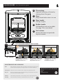
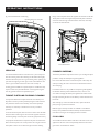
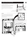
QUICK GUIDE Your Charnwood at a glance
®
a
b
b
a
c
Door handle
Pull up to open
d
Riddler handle
Pull handle in and out to riddle.
See page 5 for more detail
e
Fuel retainer
Ensure fuel does not protrude
beyond retainer
e
c
Throat plate
Improves efficiency of stove by
slowing down flue gases
Door
Keep closed when stove is in use
d
LIGHTING AND CONTROLLING THE FIRE
p5
p6
Boost Nominal Output Low Output
Air control
Add kindling and paper or
firelighters. Keep air control
fully out and close door
Once kindling is alight, add
small logs. Keep air control
fully out and close door
Add larger logs once fire is
established. Air control can
be reduced to nominal
MAINTENANCE AND CLEANING
Glass
Wipe with damp, lint free cloth. Any stubborn deposits on the glass may be
removed with a proprietary stove glass cleaner or ceramic hob cleaner
Throat plate Take down once a month and clean. Sweep sooty deposits into fire
Ash pan
Ash pan is removed using tool provided. Empty ash pan before ash comes
into contact with underside of grate
Chimney
Have chimney swept twice a year. Chimney can be swept through stove
Servicing
Stove should be serviced by a professional at least once a year
p9
Suitable fuels for your Charnwood:
Wood
Peat
p4
Smokeless Fuels
OPERATING INSTRUCTIONS
®
GENERAL
should be cut and split and then left to season in a well ventilated dry
place for at least one year but preferably two years before use and
Before lighting the stove, check with the installer that the work and
should have a moisture content of less than 20%. The maximum log
checks described in the Installation Instructions have been carried
size to be used is 300mm (13.7 inches) long, 75mm (3 inches) in
out correctly and that the chimney has been swept, is sound and free
diameter.
from any obstructions. The stove is not suitable for use in a shared
flue system.
Peat
Remember that the stove will be hot and that it is made from hard
Ensure that the peat is well dried before use. Burning wet peat will
materials – ensure that you have good balance before operating the
give rise to heavy tar deposits and reduced outputs
fire.
Do not use an aerosol spray on or near the stove when it is alight.
There is a risk of explosion or flash ignition of the spray.
When using the stove in situations where children, aged and/or
infirm persons are present, a fireguard must be used to prevent
accidental contact with the stove. The fireguard should be
manufactured in accordance with BS 8423:2002.
The stove is suitable for intermittent operation.
FUEL
Please pay careful attention to the special points made with each
type of fuel as they will help you to get the best from your stove. It
must be remembered that only smokeless fuels may be burnt in
smoke control areas on this stove. If you are not sure whether you
are in a smoke control area, please check with your Local Authority.
At first you may find it helpful to try several fuels to find the most
suitable. If you are unable to obtain the fuel you want, ask your
supplier, or an approved fuel distributor, to suggest an alternative.
PETROLEUM COKE IS NOT SUITABLE FOR USE ON THIS
APPLIANCE. ITS USE WILL INVALIDATE THE GUARANTEE.
Smokeless Fuels
Only authorised smokeless fuels may be burned in smoke control
areas on this appliance. Your local fuel supplier or stove shop will be
able to advise you which fuels are available locally. Take care to only
burn good quality fuels in order to obtain the greatest efficiency and
to maintain the life of the appliance.
Recommended smokeless fuel is HomeFire.
Wood
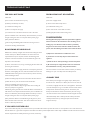
Door Handle
Only dry well seasoned wood logs should be burnt on this appliance
Air Control
Riddler
Fig. 1 Stove Controls
as burning wet unseasoned wood will give rise to heavy tar deposits
in the stove, on the glass and within the chimney. For the same
reason hard wood is better than soft wood. Burning wet unseasoned
wood will also result in considerably reduced outputs. The wood logs
5
OPERATING INSTRUCTIONS
®
OPERATING INSTRUCTIONS
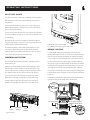
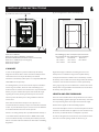
MULTIFUEL GRATE
Your Charnwood stove is fitted with a multifuel grate which enables
both solid fuels and wood to be burned effectively. The grate has
two positions:
1) In the solid fuel position the grate bars are vertical with gaps in
between allowing primary combustion air to come up through the
grate and through the fuel bed.
2) In the wood position the grate bars are horizontal. In this position
ash is able to build up on the grate as is necessary for effective wood
or peat burning.
Movement of the grate from one position to the other is effected
using the riddler handle, as shown in Fig. 3. To put the grate into the
Pull handle in and out to riddle
solid fuel position, pull the handle out fully.
Fig. 3 Riddling and setting the grate: C Four Insert
To riddle the appliance, pull the riddler handle rapidly in and out
several times. When burning wood or peat, the ash should be
BEFORE LIGHTING
allowed to build up and riddling should only be carried out once or
For best results when burning smokeless fuel the undergrate
twice a week, using the glove provided if necessary.
blanking plate needs removing. To remove the undergrate blanking
CONTROLLING THE FIRE
plate start by removing the fuel retainer, this will need to be lifted
out at an angle to avoid knocking the stove. Once the fuel retainer
The rate of burning and hence the output is controlled by the air
has been cleared, lift out the left and right grate plates which will
control (see Fig. 2).
allow access to grate assembly. Carefully remove the grate assembly
Open the air control fully (boost position) when lighting or when
by lifting the grate support bars from underneath. Lift out the rear
rapid burning is required. It should not be left fully open for long
grate support to reveal the undergrate blanking plate. Applying
periods as this can cause over-firing or excessive smoke production.
equal pressure to both sides, push up the undergrate blanking plate
For a higher burning rate move the air control to the ‘nominal
from the hooks on the undergrate air inlet and remove and keep for
output’ position or for low burning to the fully closed position.
future use.
When the fire is burning normally the air control gives enough
Reassemble by following the above steps ensuring that the middle
airwash to keep the glass clean. However, it will not always be
grate bar is located in the riddler slide as shown below.
possible to keep the glass clean with the air control fully closed.
Undergrate
Blanking Plate
Push up
Rear Grate Support
LH Grate plate
RH Grate plate
Boost
Nominal
Output
Low
Output
Grate Assembly
Fig. 2 Air control
6
Fuel Retainer
Middle Grate bar
in riddler slide
OPERATING INSTRUCTIONS
®
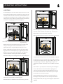
LIGHTING
On initial lighting, the stove may smoke and give off an odour as the
silicon paint with which the firebox is painted reacts to the heat. This
is normal and will cease after a short time, but meanwhile the room
should be kept well ventilated. At first only light a small fire and burn
it slowly for two hours to allow any residual moisture in the chimney
to evaporate. The lighting process is shown in Figs. 4-7.
Fig. 6 Adding larger logs
stove with larger logs to the required fuel load. Logs should be no
more than 75mm in diameter and 300mm long. Close the door.
Maintain the air control at maximum at this stage.
Once long flames appear over the fire, reduce the air control to the
Fig. 4 Initial firing
When burning wood only, light the stove using dry kindling wood
and paper or fire lighters. It is recommended that you use
approximately 1kg to 1.2kg of kindling. Put the paper, or fire
lighters, and kindling in the firebox and cover with a few small dry
logs. Open the air control fully (see Fig. 2). Light the paper or fire
lighters. The door may be left cracked open for a few minutes to
assist the combustion and heat up the firebox more quickly.
Fig. 7 Fire well underway
When the kindling wood is well alight add a few more small logs and
‘nominal output’ setting. Once the fire is well established - with each
log alight at the top - the air setting can be reduced again, depending
on the type of fire required. If at any stage the flames start to go out
or the glass begins to discolour, a higher setting is required. To
achieve this, pull the air control back out to re-establish a consistent
burn.
Once the fire is up to temperature the airwash system will begin to
work, so allow the fire to become hot before adjusting the air
control to the required setting. During the lighting period, do not
leave the stove unattended. Do not leave the door open except as
directed above to avoid excessive smoke.
When relighting the stove, leave the ash on the base unless it is
Fig. 5 Building up the fire
becoming too deep, in which case some of it may be removed. If
close the door, but leave the air control fully open.
burning smokeless fuel, clear the grate and empty the ashpan before
When the flames are established around the smaller logs, load the
relighting.
7
OPERATING INSTRUCTIONS
®
REDUCED BURNING
When burning smokeless fuel follow the same lighting process as
shown in figures 4-7 but use small kindling at first and then 1.9kg of
For reduced burning the fire door must be closed.
heavier section (25mm square section) wood to give a good firebed.
When burning wood in areas that are not smoke controlled, load
Once the heavier section wood has established flame, add the
some large logs on the fire and allow to burn for half an hour before
mineral fuel, shut the door and pull the slider fully out. Push the
closing the air control (this will help to reduce tar deposits in the
slider in to desired setting once the fire is established in the coal.
chimney). Some experimentation may be necessary to find the
setting most suitable for the type of fuel being used and the draw on
REFUELLING
the chimney.
Keep the firebox well filled but do not allow fuel to spill over the top
To revive the fire, empty the ashpan (if burning fuel other than
of the fuel retainer.
wood), riddle the fire, and open the air control to maximum. When
Logs should be evenly distributed, filling the firebed to give the most
the fire is burning well load on more fuel as necessary and adjust the
pleasing flame pattern. The air control must be fully opened after
air control to the desired setting.
refuelling until the flames are established above the fire. It is best to
CLEANING AND MAINTENANCE
refuel on to a hot fire bed of ash. If at this point the fire starts to die,
Cleaning
the door must be cracked open until the fire is revived. If the fire has
started to die down before refuelling, then more kindling wood must
The stove is finished with a high temperature paint which will
be added, the air control opened fully and the door cracked open to
withstand the temperatures encountered in normal use. This may be
re-establish the firebed before adding fresh fuel. This will avoid
cleaned with a damp lint-free cloth when the stove is cold. Should re-
excessive smoke emission.
painting become necessary, high temperature paints are available
from your supplier or from stove shops.
Care should be taken, especially when burning wood, that fuel does
not project over the fuel retainer or damage to the glass may be
Cleaning the Glass
caused when the door is closed. It can also cause blackening of the
Most deposits on the glass may be burnt off simply by running the
glass. Maximum filling height is such that logs cannot fall from the fire
fire at a fast rate for a few minutes. If it becomes necessary to clean
when the door is opened. In smoke controlled areas do not fill the
the glass then open the door and allow it to cool. Clean the glass
stove above the level of the air holes in the back bricks, as
using a damp cloth and then wiping over with a dry cloth. Any
overloading can cause excess smoke. Liquid fuels are not to be used
stubborn deposits on the glass may be removed with a proprietary
on this appliance.
stove glass cleaner or ceramic hob cleaner. Do not use abrasive
When relighting the stove, leave the ash on the base if burning
cleaners or pads as these can scratch the surface which will weaken
wood, unless it is becoming too deep, in which case some of it may
the glass and cause premature failure.
be removed. If burning solid fuel, clear the grate and empty the
When Not in Use
ashpan before relighting.
If the fire is going to be out of use for a long period (for instance in
ASH CLEARANCE
the summer) then to prevent condensation, and hence corrosion,
The ashpan should be emptied regularly before it becomes too full.
the air control should be left fully open and the fire door left ajar. It
Never allow the ash to accumulate in the ashpan so that it comes in
is also advisable to sweep the chimney and clean out the fire.
contact with the underside of the grate as this will seriously damage
Spraying the inside of the door and firebox with a light oil, such as
the grate bars. The ashpan is handled using the tool provided. Care
WD40, will also help to keep all internal parts working well. After
should be taken to ensure that ash is cool before emptying it into
long periods where the fire has been out of use, the chimney and
plastic liners or bins.
appliance flueways should be cleaned before lighting.
To make ash removal easier there is a special Charnwood ash carrier
Door Seals
available. This may be purchased from your supplier or, in case of
For the fire to operate correctly it is important that the door seals
difficulty, directly from Charnwood.
are in good condition. Check that they do not become worn or
frayed and replace them when necessary.
8
OPERATING INSTRUCTIONS
®
Fig. 9 Throat Plate Position and Lowering
flange on the side plates. Raise the opposite side and slide so that the
throat plate is central and supported by both side plates. Slide back
Retaining flanges on side plate
so that the recessed edge at the back of the underside, rests neatly
on the face of the back brick.
Brick Throat Plate
Throat Plate Position
SERVICING
CHIMNEY SWEEPING
It is recommended that the fire is serviced once a year to keep it in
The chimney should be swept at least twice a year. It will generally be
first class working order. After cleaning out the firebox thoroughly,
possible to sweep the chimney through the appliance.
check that all internal parts are in good working order, replacing any
First remove the fuel retainer and the throat plate. Then sweep the
parts that are beginning to show signs of wear. Check that the door
chimney ensuring that soot is removed from all horizontal surfaces
seal is in good condition and that the door seals correctly. A
after sweeping.
servicing guide is available on request. Repairs or modifications may
only be carried out by the Manufacturer or their approved agents.
In situations where it is not possible to sweep through the appliance
Use only genuine Charnwood replacement parts.
the installer will have provided alternative means, such as a soot
door. After sweeping the chimney the appliance flue outlet and the
THROAT PLATE AND FLUEWAY CLEANING
flue pipe connecting the stove to the chimney must be cleaned with a
It is important that the throat plate and all the stove flueways are
flue brush.
kept clean in order to prevent potentially dangerous fume emission.
After clearing any soot from within the stove, replace the throat
They should be cleaned at least monthly, and more frequently if
plate (see Fig. 9) and the fuel retainer.
necessary. It is necessary to let the fire out to carry out these
Different types of sweep’s brushes are available to suit different
operations.
flueways. For prefabricated insulated chimneys the manufacturers
To remove the throat plate, slide it forward so that it clears the back
instructions with regard to sweeping should be consulted.
brick, then slide it either right or left so that the opposite side clears
CO ALARM
the retaining flange on the side plate and can be gently lowered. Any
sooty deposits should then be swept from the plate and into the fire.
Your installer should have fitted a CO alarm in the same room as the
Return the throat plate to its correct position- At an angle, insert the
appliance. If the alarm sounds unexpectedly, follow the instructions
throat plate so that it sits on either the right or the left retaining
given under “Fume Emission” below.
9
TROUBLESHOOTING
®
FIRE WILL NOT BURN
FIRE BLAZING OUT OF CONTROL
Check that:
Check that:
a) the air inlet is not obstructed in any way,
a) The door is tightly closed.
b) chimneys and flueways are clear,
b) The air control slider is fully closed.
c) a suitable fuel is being used,
c) A suitable fuel is being used.
d) there is an adequate air supply,
d) Door seals and air control slider are intact.
e) an extractor fan is not fitted in the same room as the stove.
e)Undergate plate is fitted when burning wood.
f) there is sufficient draw in the chimney. Once the chimney is warm a
draught reading of at least 1.25 mm (0.05 inches) water gauge
FUME EMISSION
(12Pa) should be obtained
Warning Note: Properly installed and operated this appliance
will not emit fumes. Occasional fumes from de-ashing and re-
g) The Undergrate Blanking Plate is fitted for burning wood and
fuelling may occur. Persistent fume emission is potentially
removed for burning smokeless fuels.
dangerous and must not be tolerated. If fume emission does
persist, then the following immediate actions should be taken:
BLACKENING OF DOOR GLASS
Differences in chimney draughts mean that the best settings of the air
a) Open doors and windows to ventilate the room.
controls will vary for different installations. A certain amount of
b) Let the fire out and safely dispose of the fuel from the
experimentation may be required, however the following points
appliance.
should be noted and with a little care should enable the glass to be
kept clean in most situations:
c) Check for flue or chimney blockage, and clean if required.
a) Wet or unseasoned wood, or logs overhanging the front fence will
d) Do not attempt to re-light the fire until cause of fume has
cause the glass to blacken
.
b) The airwash relies on a supply of heated air to keep the glass clean.
been identified. If necessary, seek professional advice.
The most common cause of fume emission is flueway or chimney
Therefore, when lighting the stove, allow the firebed to become well
blockage. For your own safety these must be kept clean.
established before closing the air control. This may also be necessary
when re-fuelling the stove.
CHIMNEY FIRES
c) When re-fuelling keep the fuel as far back from the front fence as
possible. Do not try to fit too much fuel into the firebox.
If the chimney is thoroughly and regularly swept, chimney fires
d) Do not completely close the air control.
It is always more difficult to keep the glass clean when running the
air control, and tightly close the door of the appliance. This should
should not occur. However, if a chimney fire does occur close the
cause the chimney fire to go out in which case the controls should
stove very slowly for long periods.
If blackening of the glass still occurs check that all flue connections are
be kept closed until the stove has gone out. The chimney and
well sealed. It is also important that the chimney draw is sufficient and
flueways should then be cleaned. If the chimney fire does not go
that it is not affected by down-draught. When the chimney is warm a
out when the above action is taken then the fire brigade should be
draught reading of at least 1.25 mm (0.05 inches) water gauge
called immediately. After a chimney fire the chimney should be
(12Pa) should be obtained. Some blackening of the glass may occur
carefully examined for any damage. Expert advice should be
below the level of the fuel retainer. This will not obscure the view of
sought if necessary.
the fire or affect its performance.
IF YOU NEED FURTHER HELP
If you need further help with your Charnwood then your Installer will be able to provide the answers to most questions. Your Local Charnwood
Premier Dealer has a great deal of experience and will also be able to provide helpful advice. Further help is available from the Charnwood Customer
Services department who will be pleased to give advice, if necessary.
10
INSTALLATION INSTRUCTIONS
®
SPECIFICATION
HEALTH AND SAFETY PRECAUTIONS
Please take care when installing the stove that the requirements of
Wood
Multi Fuel
the Health and Safety at Work Act 1974 are met.
Output
5kw
4.9kw
Some types of fire cement are caustic and should not be allowed to
Stove Weight
105kg
105kg
Flue Gas Temperature
279°C
282°C
Flue Gas Mass Flow
4.4g/s
4.3 g/s
installation then please use appropriate protective equipment.
Average refuelling cycle
0.75hrs
1.0 hr
There must not be an extractor fan fitted in the same room as the
Min Flue Draught
12Pa
12Pa
stove as this can cause the appliance to emit fumes into the room.
CO at 13% 02
0.08%
0.18%
The combustion air supply ducting must be connected to a suitable,
Maximum Log Size
300mm long
x 75mm diameter
come into contact with the skin. In case of contact, wash with plenty
of water.
If there is a possibility of disturbing any asbestos in the course of
permanently open air inlet. See ‘Air supply’ section for details. This
stove is capable of intermittent operation. This stove is not suitable
Multifuel results obtained using ‘Homefire’ fuel burned over a 1hr period.
Wood Figures were achieved burning seasoned hardwood logs over a 45
minute refuelling period.
for use in a shared flue system.
In addition to these instructions the requirements of BS 8303 and
BSEN 15287-1:2007 must be fulfilled. Local Authority Bylaws and
CO ALARMS
Building Regulations, including those referring to national and
European Standards, regarding the installation of Solid Fuel burning
Building regulations require that whenever a new or replacement
appliances, flues and chimneys must also be observed.
fixed solid fuel or wood/biomass appliance is installed in a dwelling a
carbon monoxide alarm must be fitted in the same room as the
UNPACKING THE STOVE
appliance. Further guidance on the installation of the carbon
The stove arrives bolted to its pallet and covered with a cardboard
monoxide alarm is available in BS EN 50292:2002 and from the
box. The bands are first removed and then the box is lifted, then the
alarm manufacturer's instructions. Provision of an alarm must not be
stove is released from the pallet by removing the 2 brackets using a
considered a substitute for either installing the appliance correctly or
13mm spanner. The bracket on the rear is removed with a 10mm
ensuring regular servicing and maintenance of the appliance and
Spanner.
chimney system.
The pallet is intended to be cut up and used for kindling fuel
AIR SUPPLY
The ducted air supply provides combustion air to the stove, through
an 80mm diameter duct. One end of the air supply ducting is
connected to the stove and the other can be terminated in the room
if the house design air permeability is greater than 5.0m³/(h.m²), or
can be ducted directly to outside. The ducting must be less than
5.5m long and must not have more than five 90° bends and two 45°
elbows. In both cases the inlet must be permanently open and the
duct free of any constrictions. The inlet must have a suitable open
grille fitted to prevent entry by vermin. A spillage test must be
carried out during commissioning to verify adequate supply to the
stove.
11
INSTALLATION INSTRUCTIONS
®
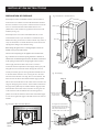
Fig. 11 Limiting Dimensions of Surround and Opening
Fig. 10 Minimum distances from combustibles
D
500mm
A
C
A
B
A
600mm
C
B
E
The shaded grey area on the face of the surround is
the minimum flat area required for inset installation.
Dimension A: 280mm
Dimension B: 251mm (Building regulations)
Recommended:390mm (extension of door over hearth)
Dimension C: 1000mm (in front of glass)
Dimension D: 310mm
Dimension E: 12mm
Dimension A:
Min. 405mm
Max. 430mm
Dimension B:
Min. 555mm
Max. 565mm
Dimension C:
Min. 380mm
CHIMNEY
In order for the appliance to perform satisfactorily the chimney
Single wall flue pipe is suitable for connecting the stove to the
height must not be less than 4 metres measured vertically from the
chimney but is not suitable for using for the complete chimney.
outlet of the stove to the top of the chimney. The internal
It is important that there is sufficient draw in the chimney and that
dimensions of the chimney (either square or round) MUST NOT BE
the chimney does not suffer from down-draught. When the chimney
LESS THAN 150 mm (6 inches).
is warm the draw should be not less than 1.25mm (0.05 inches)
If an existing chimney is to be used it must be swept and checked, it
water gauge (12.pa). If it is found that there is excessive draw in the
must be in good condition, free from cracks and blockages, and
chimney then a draught stabiliser should be fitted. If in doubt about
should not have an excessive cross sectional area. If you find that the
the chimney seek expert advice.
chimney is in poor condition then expert advice should be sought
regarding the necessity of having the chimney lined. If it is found
HEARTH AND FIRE SURROUND
necessary to line the chimney then a lining suitable for Solid Fuel
The stove must be installed above a fireproof hearth in accordance
must be used.
with local building regulations (See fig.10 for dimensions). If in doubt
If the stove has been fitted in the place of an open fire, it is
as to the positioning of the stove expert advice should be sought
recommended that the chimney is swept one month after installation
either from the supplier or the local building inspector.
to clear any soot falls which may have occurred due to the difference
If a wooden mantelpiece or beam is used in the fireplace it should be
in combustion between the stove and the open fire.
a minimum of 310mm above the appliance. In some situations it may
If there is no existing chimney then a prefabricated block chimney or
be necessary to shield the beam or mantelpiece to protect it.
a twin walled insulated stainless steel flue to BSEN 15287-1:2007
In order for the appliance to fit into the fire surround there must be
can be used either internally or externally. These chimneys must be
a flat area around the opening. Details are shown in Fig. 11.
fitted in accordance with the manufacturers instructions and Building
Regulations.
12
INSTALLATION INSTRUCTIONS
®
Fig. 13 Installation in standard chimney
PREPARATION OF FIREPLACE
If the fireplace contains combustible materials, inlet and outlet air
vents with an area of 246cm² each must be fitted below and above
the stove convection case to provide a continual air flow around the
Closure plate
stove. It is recommended that Calcium Silicate board is used
(130mm board, with a 100mm air gap between the stove and the
insulation (see Fig. 12).
Flue
If the fireplace does not contain combustible materials, it is still
recommended to have a layer of insulation or ventilate the space
Flue collar
between the casing and the outer wall. The insulation may consist of
a layer of mineral fibre or calcium silicate board. Insert this into the
opening before sliding in the convection casing.
Before fitting the appliance into an existing fireplace remove the
fireback and any loose in-fill material.
The surround and opening for the appliance must conform with
Fig.11. The flat area around the opening should be a minimum of
500mm wide and 600mm high. Ensure that the hearth and the base
in the opening are flat, level, and at right angles to the surround.
External air kit
to outside wall
The air supply inlet can be fitted in the room or outside, in
accordance with the requirements in 'Air Supply' section (p11). The
inlet grille must not constrict the airflow through the duct and it
must be permanently open. A semi rigid aluminium flexible duct of
Fig. 14 Air Supply
no less than 80mm diameter is used to bring the air to the stove .
The duct must be less than 5.5m long, have no more than five 90º
Warm air
bends and two 45º elbows. The 80mm diameter spigot, provided
with the stove should be fitted on the outside of the convection case,
using two self tapping screws and the duct should be terminated on
the spigot with a jubilee clip. The 100mm diameter spigot provided
Flue
should be fitted to the inside of the convection case using two nuts
on the outside and the self adhesive foam should be glued into
Optional air ducts
can carry heat
to other rooms
position around the circumference of the inside of the 80mm spigot
in order to seal against the spigot on the back of the stove when it is
installed.
Fig. 12 Fireplace With Combustible Material
Air supply duct must be fitted
to bring cool air into the stove.
This could be through an external
wall, from another room, or
from the same room as the stove.
100mm air gap must be ventilated with inlet
and outlet apertures of minimum 246cm²
Non Combustible
Calcium
silicate board
130mm
Rear outlet of stove
Non Combustible
Air supply
Top of stove
13
Flexible tube
ø80mm
INSTALLATION INSTRUCTIONS
®
FITTING THE CONVECTION CASING, FLUE
1. Attach flue collar to length of flexible flue liner
PIPE AND STOVE
Having prepared the fireplace as described, the convection case,
stove and flue pipe can now be fitted.
1. ATTACH FLUE COLLAR TO THE FLUE PIPE
Upper flue collar
Collar can be positioned as necessary
depending on required angle of flue
Flue liner
Fix collar to flue with
screws either side
Self-clinching studs
Some liner manufacturers recommended the use of a rigid pipe with
the liner - please refer to the liner manufacturers instructions. Fix the
upper flue collar to the flue pipe through the screw holes in the side
of the ring. The flue collar can be attached at any of 4 positions
2. Insert convection casing into opening
depending on the required angle of the flue.
It is vital that the connections at both ends of the flue pipe are well
sealed. The flue pipe and collar can be sealed with fire cement
and/or a gasket.
2. INSERT THE CONVECTION CASING INTO THE OPENING
Make sure the four self-clinching studs are in the holes in the flue
collar, pointing downwards. Slide the convection casing into position
in the opening until the flue outlet lines up with the flue pipe. Any
excess air ducting still in the opening can be pulled out at the
external termination point and trimmed to fit the grille selected.
Ensure that the air supply duct is not kinked during the fitting
process.
3. MAKE FLUE CONNECTION
Reaching through the flue outlet, bring the flue collar down through the outlet
until the studs line up with the four holes in the convection casing. Use nuts to
secure the studs into place.
Flue pipe
Sealed with gasket
Upper flue collar
Convection casing
14
INSTALLATION INSTRUCTIONS
®
4. SECURE THE CASING TO THE HEARTH
Secure the stove by inserting screws through the holes in the base (see
diagram).
5. MAKE GOOD THE OPENINGS AND FILL WITH INSULATION
Make good the opening at the top and sides of the convection casing
ensuring that a good seal is made with the side flanges. It is
recommended to use heat resistant plaster on the wall surrounding the
stove.
Follow the liner manufacture’s recommendations regarding insulating
the liner.
If for any reason it is not going to be possible to sweep the chimney
through the appliance, a soot door must be fitted.
6. SLIDE IN STOVE
Carefully slide the stove into the convection casing until the
flue outlet lines up with the flue collar and the air inlet
engages at the rear of the stove.
7. INSERT COACH BOLTS
From the inside of the stove, insert coach bolts into
slots A and B so that they hang down into the stove.
These are held in place by the clips and will secure the
flue collar.
A
A
B
15
B
INSTALLATION INSTRUCTIONS
®
8. SECURE THE FLUE ADAPTORS
Flue pipe
Working from the inside of the stove, push the flue collar up through
the flue outlet to meet the upper flue collar, so that the coach bolts
Convection casing
come down through the holes. Secure bolts with nuts.
Upper flue collar
All flue connections must be well sealed. Check that the flue pipe is
not obstructed or restricted in any way and that all joints are well
sealed.
Inner flue collar
Sealed with 8mm
self-adhesive fibreglass webbing seal
Wall of stove
Secure with nut here
SIDE PIECES
Side pieces
Remove air control knob, undo both allen key bolts in lower panel
and remove it. Fit machine screws through the holes in the lower left
and right hand side to secure the lower end of the side pieces. The
tops of the side pieces are secured with a machine screw. Refit the
lower panel and air slider knob.
9. ATTACH TOP CAP
Slide the cast top cap (a) into position. Finally, with the door
open, insert hex head screw (b) from the underside of the top
shelf. Tighten to secure the assembly into position.
a. Cast top cap
b. Hex head screw
16
INSTALLATION INSTRUCTIONS
®
Further information on the requirements of the Clean Air Act can be
PRE LIGHTING CHECK
found here: http://smokecontrol.defra.gov.uk/
Before initial lighting check the following points:
Your local authority is responsible for implementing the Clean Air
1. The bottom grate bars must all be fitted and should move freely
Act 1993 including designation and supervision of smoke control
and easily when the riddling mechanism is operated.
areas and you can contact them for details of Clean Air Act
2. The plates round the sides and back of the grate must be in
requirements.
position and sitting correctly.
3. The throat plate must be fitted in the roof of the appliance (as
shown in Fig. 9).
4. Check that the front fence is fitted correctly and that the door
closes properly.
COMMISSIONING
On completion of the installation allow a suitable period of time for
the fire cement and mortar to dry out before lighting the fire. Check
to ensure that smoke and fumes are taken from the appliance up the
chimney and emitted safely. Also check all joints and seals. On
completion of the installation and commissioning please leave the
operating instructions with the customer and advise them on the use
of the appliance.
CAA AND SMOKE CONTROL
The Clean Air Act 1993 and Smoke Control Areas
Under the Clean Air Act local authorities may declare the whole or
part of the district of the authority to be a smoke control area. It is
an offence to emit smoke from a chimney of a building, from a
furnace or from any fixed boiler if located in a designated smoke
control area. It is also an offence to acquire an "unauthorised fuel"
for use within a smoke control area unless it is used in an "exempt"
appliance ("exempted" from the controls which generally apply in
the smoke control area).
The Secretary of State for Environment, Food and Rural Affairs has
powers under the Act to authorise smokeless fuels or exempt
appliances for use in smoke control areas in England. In Scotland and
Wales this power rests with Ministers in the devolved
administrations for those countries. Separate legislation, the Clean
Air (Northern Ireland) Order 1981, applies in Northern Ireland.
Therefore it is a requirement that fuels burnt or obtained for use in
smoke control areas have been "authorised" in Regulations and that
appliances used to burn solid fuel in those areas (other than
"authorised" fuels) have been exempted by an Order made and
signed by the Secretary of State or Minister in the devolved
administrations.
17
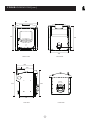
C FOUR I DIMENSIONS (mm)
®
485
595
550
ø77
75
200
400
FRONT VIEW
BACK VIEW
380
115
265
ø155
555
(for 6" flue)
595
310
PLAN VIEW
SIDE VIEW
18
C-FOUR I PARTS LIST
®
Issue B
17
12
19
20
13
14
8
43
51
18
11
52
10
8
7
9
6
56
54
53
50
43
42
5
21
62
23
22
59
49
63
64
65
4
25
48
26
61
24
28
41
40
55
57
58
15
39
29
44
45
16
2
27
30
33
31
34
46
47
38
35
36
37
60
32
Item
Part No.
Description
Item
Part No.
Description
1*
2
3*
4
5
6
7
8
9
10
11
12
13
14
15
16
17
18
19
20
21
22
23
24#
25
26#
27#
28
29#
30
31
32
33
34
008/PV21
006/PV19
008/PV55
004/KV23
010/TR027
010/TR028
011/PV26
011/TR029S
010/ER036
008/FFB125
011/TR031
011/TR032
008/FFW005
008/FFB030
002/BR017
010/TR021
010/TR090
010/TR076
004/GR090
008/FFS006
004/BR021
002/BR020
008/BW39/S
002/BR001/A
002/PV13
004/TR068
004/TR069
008/FFW026
002/BR012
004/BR014
008/FFW015
008/FFB007
008/BR013
010/TR020
Door Seal
Glass
Glass Seal
Glass Retainer
RH Sideplate
LH Sideplate
Side Gasket
Rear Brick Set
Brick Retaining Washer
M6x45 Coach Bolt
Brick Throat Plate
Upper Throat Plate Brick
M8 Light Penny Washer
Hex Hd Screw M6x40
Fuel Retainer
Lower Front Panel
Upper Flue Adaptor
Lower Flue Adaptor
Fastener Retainer
M6x10 Sltd Cheese Hd Screw
Hinge Shim
Hinge Casting
Hinge Pin Set 5mm x 25mm
Door Assembly
Door Latch
RH Side Trim
LH Side Trim
M6 Heavy Brass Washer
Handle Casting
Handle Pivot Pin
Thackery Washer
M8x100 Allen Hd Bolt
Wooden Handle
Air Box Cover Plate
35
36
37
38
39
40
41
42
43
44
45
46
47
48
49#
50
51#
52
53
54
55
56
57
58
59
60
61
62
63
64
65
66*
004/GR086
008/TR047
008/AY37
008/BR052
004/TR007
004/CR005
008/CR006
004/CR048
008/MR125
008/ES36/01
004/BR015
008/CR063
004/CR064
012/TR011
001/TR010
010/TR026
002/GR051
008/FFS049
010/TR099
002/CG01
010/GR057
010/GR056
010/GR006
010/GR042
010/GR044
004/TR017
010/TR040
004/TR045
004/TR042
010/TR044
008/MR067
008/PX95
Air Control Rod
DEFRA Stop
Air Control Knob
Felt Washer
Air Inlet Slide
Air Control Plate Assy
Airbox Upper Gasket
80mm Spigot
100mm Spigot
Brass Ball Catch
Clicker Retainer Plate
Blanking Plate Gasket
Coverplate
Serial No Plate
Firebox
Convection Casing
Cast Top Cap
Hex Hd Screw M8x45
Undergrate Blanking Plate
Bottom Grate Bar
LH Grate Plate
RH Grate Plate
Grate Support
Front Grate Support
Rear Grate Support
Ashpan
Mover Bar
Riddler Arm Cover
Riddler Slide
Riddler Rod
Riddler Handle
Ashpan Tool
To obtain spare parts please contact your local stockist
giving Model, Part No. and Description. In case of
difficulty contact the manufacturer at the address
shown.
This drawing is for identification purposes only.
* These items are not shown on the drawing
# Please specify colour when ordering.
charnwood
T: + 4 4
BISHOPS WAY, NEWPORT, ISLE OF WIGHT
( 0 ) 19 8 3
5 37 7 9 9
•
F : + 4 4
( 0 ) 19 8 3
19
5 37 7 8 8 •
PO30 5WS, UNITED KINGDOM
W W W. C H A R N WO O D . C O M
®
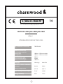
14
A.J WELLS & SONS LTD
Bishops Way, Newport, Isle of Wight PO30 5WS, United Kingdom
A Division of A.J.Wells & Sons Limited Registered in England No. 03809371
EN13229:2001/A2:2004/AC:2007
C Four I
ROOMHEATERS FIRED BY SOLID FUEL
TR-CPD-2014
EC certificate of conformity
no:
Minimum distance to
combustible materials:
Casing Side:
Casing Rear:
100mm + 130mm insulation
100mm + 130mm insulation
Front surround, side:
Front surround above:
Room, in front of glass:
280mm
310mm
1000 mm
Fuel type
Wood logs
Multi Fuel
Emission of CO in combustion
products:
0.08 %
0.18%
Flue gas temperature:
279 °C
282 °C
Space heating thermal output:
5 kW
4.9kW
Energy efficiency:
80 %
77.3%
20
your premier dealer
charnwood
T: + 4 4
BISHOPS WAY, NEWPORT, ISLE OF WIGHT
( 0 ) 19 8 3
5 37777
•
F : + 4 4
( 0 ) 19 8 3
5 377 8 8
PO30 5WS, UNITED KINGDOM
•
W W W. C H A R N WO O D . C O M
®
A D i v i s i o n o f A . J . We l l s & S o n s L i m i t e d Re g i s t e r e d i n E n g l a n d N o . 0 3 8 0 9 371