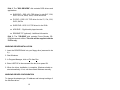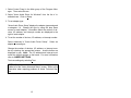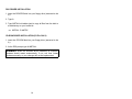
1
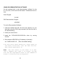
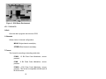
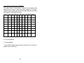
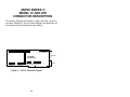
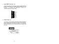
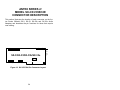
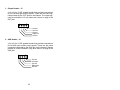
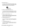
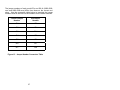
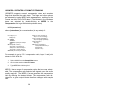
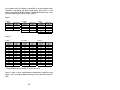
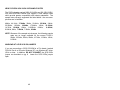
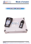
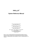
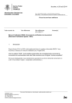
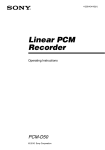
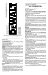
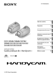
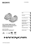
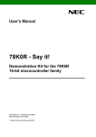
SX-3 SX-33
SX-33b SX-33e
16-BIT PRO SOUND
Digital Audio Adapter
User's Manual
January 18, 1996
ANTEX ELECTRONICS CORPORATION
16100 SOUTH FIGUEROA STREET
GARDENA, CALIFORNIA 90248
9000-2319-7006
TABLE OF CONTENTS
INTRODUCTION ......................................................................1
ABOUT DIGITAL AUDIO ..........................................................1
MINIMUM HARDWARE RECOMMENDED...............................6
ADAPTER INSTALLATION ......................................................6
JUMPER SETTINGS.....................................................6
CONNECTIONS............................................................8
DRIVER INSTALLATION..........................................................11
DISKS ...........................................................................11
WINDOWS DRIVER INSTALLATION ...........................12
WINDOWS DRIVER CONFIGURATION.......................12
DOS DRIVER INSTALLATION......................................14
CD-ROM DRIVER INSTALLATION (Z1/Z1e ONLY)......14
USING DOS DEMONSTRATION SOFTWARE: .......................15
PROBLEMS RUNNING THE DEMO .............................20
USING WINDOWS DEMONSTRATION SOFTWARE..............21
ANTEX MIXER .........................................................................25
MIXER BUSES..............................................................26
RECORD MODE ...........................................................26
PLAY MODE (Feedthrough)..........................................26
MIXER DEVICES ..........................................................26
UTILIZING
DIGITAL
AUDIO
COMPRESSION
UNDER
WINDOWS ...............................................................................28
ISO/MPEG-1 BITRATES & FORMAT EXTENSIONS ...............38
FIGURES
Figure 1. Analog-to-Digital Conversion ....................................3
Figure 2. Digital-to-Analog Conversion ....................................5
Figure 3. Setting JP7 for audio IRQx 10 ..................................7
Figure 4. Setting JP5&6 to the audio I/O address & Z.WAV address .................................................................................7
Figure 5. Z1, Z1e, SX-3, SX-33, SX-33b, SX-33e Connectors. 9
Figure 6. DOS Demo Environment ..........................................16
Figure 7. The Antex Demo Window. ........................................21
Figure 8. Message Box reporting an unavailable compression
format or an invalid sample rate.........................................22
Figure 9. File Open dialog box. ................................................23
Figure 10. Antex Mixer.............................................................25
Figure 11. Z1/Z1e Connector Layout. ......................................30
Figure 12. SX-3/33/33b/33e Connector Layout. .......................34
Figure 13. Jumper Number Conversion Table .........................37
INTRODUCTION
The Series 2 and 3 Digital Audio Adapters are IBM AT compatible
add-on boards which convert high fidelity analog signals to digital
data for storage to, and retrieval from, disk.
The Series 2 and 3 adapters sample two channels of audio from
7.35 kHz to 50kHz with 16 bit resolution. They incorporate Sigma
Delta technology with 64 times oversampling, providing superior
fidelity at greater than 80 dB signal-to-noise ratio.
ABOUT DIGITAL AUDIO
In professional circles, digital audio has been with us for over 10
years. With the advent of the compact disk in 1983, digital audio
has become commonplace as a consumer item. Few will argue
that digital audio has afforded an order of magnitude improvement
in overall sound quality and signal-to-noise ratio over the best
analog systems which preceded them. But just what is digital
audio, and where and how is it used?
It is possible to use digital data transmission techniques to transmit digital audio signals by wire or radio. However, this practice
has not yet become common due to the extremely wide signal
bandwidth required to transmit real-time digital audio signals. For
the present, digital audio techniques seem largely confined to the
recording and playback of music and other audio signals where, in
a few short years, digital audio technology has all but replaced the
previous analog record/playback techniques. In the present decade we will see digital audio technology replace analog technology in most signal processing functions in both the professional
and consumer markets. It is also likely, particularly with the advent
of fiber optic cables, that digital audio technology will be utilized in
the transmission of real-time audio signals on a widespread basis.
But what is digital audio?
1
In essence, digital audio is a technological process whereby an
analog audio signal (produced when sound waves in the air excite
a microphone) is first converted into a continuous stream of numbers (or digits). Once in digital form, the signal is extremely immune to degradation caused by system noise or defects in the
storage or transmission medium (unlike previous analog systems). The digitized audio signal is easily recorded onto a variety
of optical or magnetic media, where it can be stored indefinitely
without loss. The digitized signal is then reconverted to an analog
signal by reversing the digitizing process. In digital audio record/playback systems, each of these two functions is performed
separately. In digital audio signal processing systems (where no
record/playback function occurs) both analog-to-digital and digitalto-analog conversion processes occur simultaneously. A variety of
techniques are possible, but the most common method by which
audio signals are processed digitally is known as linear pulse
code modulation, or PCM. Let's take a brief look at how PCM
works.
Converting an analog signal to digital is a twostage process, sampling and quantization.
This
is illustrated in Figure 1.
At regular intervals, a sample-and-hold circuit instantaneously
freezes the audio waveform voltage and holds it
steady while the quantizing circuit selects the
binary code which most closely represents the
sampled voltage. Most digital audio is based on
a 16-bit PCM system. This means that the quantizer has 65,536 (216) possible signal values to
choose from, each represented by a unique sequence of the ones and zeroes which make up the
individual code "bits" of the digital signal.
The number of these bits generated each second is a function of
sampling rate. At a relatively low sampling rate of 8 kHz (suitable
for voice) far fewer code bits are produced each second than, for
example, at the 44.1 kHz sampling rate used for commercial
compact disks. For a two-channel stereo signal at a 44.1 kHz
sampling rate, some 1.4 million bits are generated each second.
2
Figure 1. Analog-to-Digital Conversion
That's about five billion bits per hour, which is why you'll need at
least an 800 Megabyte hard disk to record an hour of compact
disk quality music.
To visualize the analog-to-digital conversion process, refer to Figure 1. At the top is one cycle of an analog input signal wave.
We've used a simple sine wave to make visualization easier. In
this example, the signal has a peak-to-peak amplitude of 20 units,
measured by the scale on the left. The sampling frequency is
many times higher than the signal being sampled and is shown
along the bottom of Figure 1. Once for each cycle of the sampling
frequency, the sample-and-hold circuit "slices" the input signal,
allowing the quantizing circuit to generate a (digital) number equal
to the closest (of the 65,536 possible discrete values) quantization
value of the input signal at the time the sample is taken. This repeats for each successive cycle of the sampling frequency and
3
the quantizer generates a continuous "bit stream" which represents the quantized signal. The continuous stream of digital audio
information is converted into a digitally modulated signal using a
technique known as linear pulse code modulation.
Digital-to-analog conversion (used in playback) is the exact opposite of the analog-to digital conversion process and is illustrated in
Figure 2.
In digital-to-analog conversion, the PCM bitstream is converted at
the sampling frequency to a continuously changing series of
quantization levels which are individual "steps" of discrete voltage
equal to the quantization levels in the analog-to-digital process.
The shape of this continuously changing stream of quantization
levels approximates the shape of the original wave. This is shown
in the top half of Figure 2. This signal is then passed through a
low-pass filter, which removes the digital "switching noise." The
end result, shown in the bottom half of Figure 2 is an analog output signal whose waveshape is a very close approximation of the
original analog input signal.
The foregoing is a very brief and, of necessity, oversimplified explanation of how digital audio works. For the interested reader,
the book Principles of Digital Audio by Ken C. Pohlmann, copyright 1985 by Howard W. Sams, is highly recommended.
4
Figure 2. Digital-to-Analog Conversion
5
MINIMUM HARDWARE RECOMMENDED
! 12MHz 386 PC or compatible
! 28mSec average access hard disk
! 1:1 Interleave hard disk controller
! Mouse
! VGA display
ADAPTER INSTALLATION
Make sure the main power to your computer is OFF. You will
need a full-size, 16 bit/AT slot. If you are unfamiliar with the internal design of your computer see its "Guide to Operations" manual
for step by step installation procedures.
Read JUMPER SETTINGS and CONNECTIONS for information
about configuring the adapter before plugging it into the slot.
JUMPER SETTINGS
The jumpers on the Z1, Z1e, SX-3, SX-33, SX-33b and SX-33e
have been preset at the factory to insure proper operation for
multimedia testing. Refer to Figures 11 & 12 in the back of the
manual for the jumper locations.
NOTE: These jumper numbers correspond to Z1/Z1e boards
marked 9000-2319-300x and SX-3/SX-33 9000-2334-300x
boards. Refer to Figure 13 for setting jumpers on earlier versions.
The interrupt is currently set to 10 by the JP7 jumper, but may be
changed to 2, 3, 5, 7, or 11 if the Windows drivers are configured
accordingly. Figure 3 illustrates the use of JP7.
6
2 3 5 7 10 11
"
"
"
"
"
"
"
"
"
"
"
"
"
"
Figure 3. Setting JP7 for audio IRQx 10
The I/O address is set to 380h, but may be changed to 180h,
220h, or 280h via jumpers JP5 and JP6. Figure 4 illustrates the
use of JP5 & 6.
NOTE: For the Z1, Z1e, SX-3, SX-33, SX-33e -The Z.WAV address shown is always used, even if no Z.WAV is present.
"
"
"
"
JP5
JP6
X
X
180h
DISABLED
X
-
220h
300h
-
X
280h
320h
-
-
380h
330h
AUDIO I/O
ADDRESS
Z.WAV
MPU-401 ADDRESS
NOTE: "X" indicates an enabled jumper
Figure 4. Setting JP5&6 to the audio I/O address &
Z.WAV address .
For Z1/Z1e only:
The joystick is enabled, but may be disabled by removing
the jumper from JP4.
The SCSI is enabled, but may be disabled by removing the
jumper from JP3. The address of the SCSI interface is
preset to CE00, but may be changed to CA00, C800, or
DE00 using JP1 and JP2.
7
If you are connecting a SCSI CD-ROM to a Z1e board
(marked F2319-4 Rev A or B) under Windows NT, use
Windows NT driver V0.8e or later.
If a Z-Wave is installed, the MPU-401 address is set by
JP5 & 6 (Note that these jumpers simultaneously set the
Audio I/O address). The available addresses are 300h,
320h and 380h(default). Figure 4 shows how the MPU401 address is selected.
CONNECTIONS
There is a five pin internal CD ROM header for connecting a
Z1/Z1e to audio output of a CD-ROM. A 50-pin header is provided on the Z1/Z1e for connecting to an internal SCSI CD-ROM.
For more information about the configuration of these and other
headers located internally on the Z1, Z1e, SX-3, SX-33, SX-33b
and SX-33e, refer to the Connector Descriptions, Figures 11 & 12,
in the back of the manual.
When the internal modifications are completed, push the adapter
firmly into an expansion slot. Take care not to bend or break any
components. The adapter should be seated firmly and the bracket
should be flush with, and secured to, the support rail along the
back edge of the computer.
Now make the connections at the back of the adapter, such as
audio input, output, microphone, etc. Refer to Figure 5 for these
connector locations on the Z1, Z1e, SX-3, SX-33, SX-33b and SX33e.
8
LINE IN
MICROPHONE
CD/AUX
OUTPUT
Z1/Z1e
15-PIN JOYSTICK
CONNECTOR
SX-3/SX-33/SX-33e
LINE IN
MICROPHONE
CD/AUX
OUTPUT
Figure 5. Z1, Z1e, SX-3, SX-33, SX-33b, SX-33e Connectors.
Audio connections are made via 4 stereo mini-phone jacks
mounted on the bracket end. From top to bottom, the jack functions are LINE IN, MIC IN, AUX/CD-ROM IN (SX-3/SX-33/
SX-33b/SX-33e is AUX IN only), and OUT (powered).
In addition, the Z1/Z1e has a 15-pin D connector located on the
bottom end of the bracket for MIDI and joystick connections. This
connector is compatible with a MediaVision joystick/midi breakout
box.
9
Audio Input:
Line:
Stereo 1/8" mini plug, 1 VRMS (2.83 Vpp) max, with an
impedance of 10K ohms.
Microphone:
Stereo 1/8" mini plug, 10 mVRMS max, with an impedance
of 10K ohms.
Aux/ CD-ROM Input (SX-3/SX-33/ SX-33b/SX-33e is AUX
only):
Stereo 1/8" mini plug, 1 VRMS(2.83 Vpp)max, with an impedance of 10K ohms.
Audio Output:
1/8" Stereo mini plug, 1 VRMS max into 8 ohms.
MIDI/Joystick Breakout Connector (Z1/Z1e Only):
DB-15 female
When adapter installation is complete and all audio connections
have been made, the computer power switch may be turned on.
10
DRIVER INSTALLATION
DISKS
Disk 1. The "WINDOWS DRIVERS" disk contains Windows
drivers and applications (Note: The DOS 3.2/Windows 2.0
drivers continue to come on a single disk):
•
ANTEXWAV.DRV - Windows Wave Driver for SX3,
SX5e, SX7, SX9, SX11, SX12a, SX20, SX22, SX23e,
SX26, SX33, SX33e, Z1, Z1e
•
SAPIZ1.DRV - OPL3 FM Synthesizer for Z1 and Z1e
•
VAPIZ1.DRV - YM3802 MIDI driver for Z1 and Z1e
•
MIDIMAP.CFG - MidiMapper config file with Z1 and
Z1e specific maps
•
ANTEXMIX.EXE, MMMIXER.DLL - Antex Mixer Applet
and DLL
•
ANTEXDEM.EXE - Antex Demo
•
OEMSETUP.INF - Windows definition file for manual
driver installation
•
SETUP.EXE and supporting files - Windows driver installation utility
•
README.TXT (optional) - Windows information
11
Disk 2. The "DOS DRIVERS" disk contains DOS drivers and
applications:
•
SX25.EXE - DOS V3.3 TSR driver for the SX7, SX9,
SX11 SX-12a, SX20, SX22, SX23e and SX26
•
Z1.EXE - DOS V3.3 TSR driver for the Z1, Z1e, SX3,
SX33, SX33e
•
SX5E.EXE - DOS V3.3 TSR driver for the SX5e
•
ADG.EXE - Digital audio player/recorder
•
README.TXT (optional) - Additional information
Disk 3. The "CD-ROM" disk contains Future Domain CDROM drivers and utilities. This disk will be supplied with the
Z1/Z1e only.
WINDOWS DRIVER INSTALLATION
1. Insert the DRIVERS disk into your floppy drive (assumed to be
A:)
2. Start Windows.
3. In Program Manager, click on File then Run.
4. Enter A:SETUP in the command line box, then press OK.
5. When the driver installation is complete, Windows should restart automatically. If not, exit then restart Windows manually.
WINDOWS DRIVER CONFIGURATION
To change the adapter type, I/O address and interrupt settings of
the Windows driver:
12
1. Select Control Panel in the Main group of the Program Manager. Then select Drivers.
2. Select "Antex Audio Driver for Windows" from the list of installed drivers. Click on Setup.
3. To set adapter type:
"Antex Audio Driver Setup" displays the adapter types assigned
to adapters 1-4. Change the type by using the drop down
menus for each adapter. Information about the number of devices, I/O address, and interrupt number are displayed to the
right of each adapter.
4. To set the number of devices, I/O address, or interrupt number:
Select Advanced in "Antex Audio Driver Setup".
adapter to reconfigure.
Select an
Change the number of devices, I/O address, or interrupt number by selecting the appropriate buttons. Invalid choices are
displayed in gray. Note: The I/O address and interrupt must
match the jumper settings on the board. For more information
refer to JUMPER SETTINGS.
Test new settings by selecting Test.
NOTE: The driver version number and date displayed in the
middle left of the "Antex Advanced Setup" screen. Refer to this
information when reporting problems to Antex Technical Support.
13
DOS DRIVER INSTALLATION
1. Insert the DRIVERS disk into your floppy drive (assumed to be
A:)
2. Type A:
3. Type INSTALL driveletter:\path to copy all files from the disk to
a subdirectory on your hard disk.
ex. INSTALL C:\ANTEX
CD-ROM DRIVER INSTALLATION (Z1/Z1e ONLY)
1. Insert the CD-ROM disk into your floppy drive (assumed to be
A:)
2. At the DOS prompt type A:INSTALL.
REMEMBER: When the Windows driver installation is complete,
Windows should restart automatically. If not, exit then restart
Windows manually, or your changes will not be implemented.
14
USING DOS DEMONSTRATION SOFTWARE:
On the enclosed disk is the demonstration software for the
Z1, Z1e, SX-3, SX-33 and SX-33e boards. Filenames are as follows:
Driver Program
Z1.EXE
DOS Demonstration Program
ADG.EXE
To run the Demonstration Software:
1. Load the included disk files into their own directory on your
hard disk using the DOS copy command (all files must be in
the same directory)
2. Install your mouse driver.
3. Install the Z1/Z1e/SX-3/SX-33/SX-33e driver by running
Z1.EXE.
4. Run the demo ADG.EXE A=(I/O Address) I=(Interrupt)
ex. C>ADG A=380 I=10
(This is the default setting.)
5.At this point there should be a short pause as
the board initializes, then the demo environment should appear(Fig. 6)
Note: The left button of your mouse is to execute a command, the right is to escape. You may
also use the highlighted letter of the command to
access it directly from the keyboard.
15
Figure 6. DOS Demo Environment
KEY COMMANDS:
Q-Quit
Quits the demo program and returns to DOS.
C-Channels
Allows choice of channel configuration.
MONO-Single channel record/play
STEREO-Dual channel record/play
T-Format
The format for encoding or decoding audio data:
PCM16 - 16 Bit Pulse Code Modulation, uncompressed.
PCM8 - 8 Bit Pulse Code Modulation, uncompressed.
PCMU8 - 8 Bit Pulse Code Modulation, uncompressed. This format is compatible with Microsoft 8
Bit WAV format.
16
ADPCM1 - Series 1 compatible Adaptive Differential Pulse Code Modulation compression.
ADPCME - Enhanced Adaptive Differential Pulse
Code Modulation compression, DVI compatible.
CDIB - Compact Disk Interactive level B compression, CD-ROM XA compatible.
CDIC - Compact Disk Interactive level C compression, CD-ROM XA compatible.
MSADPCM - Microsoft Adaptive Differential Pulse
Code Modulated compression (currently playback
only).
A-law - CCITT G.711 compression (European).
µ-law - CCITT G.711 compression (North American.
MPEG - ISO/MPEG-1, Layer I/II. MPEG is available on the Z1e, SX-33 and SX-33e only. Refer to
"ISO/MPEG-1
BITRATES
&
FORMAT
EXTENSIONS " for more information.
G.728 - CCITT CELP voice compression.
The following formats are available on the SX-3
only:
G.721 - CCITT 4-bit ADPCM compression.
G.723 - CCITT 3-bit ADPCM compression.
F-File
Audio file name to record or play.
17
I-FileFormat
The file format for recording/playback. Choices are:
ATX - The Antex default audio file format
WAV - The Microsoft audio file format
HEADERLESS - Raw digital audio data without
header information
A-SampleRate
Allows you to change the sample rate. Enter the desired
rate in Hz.(ex 44.1 kHz=44100 Hz)
Rec Vol dB
Left: < >
Right: < >
To adjust the recording volume, click the mouse over the <
or > symbol on the screen. < lowers the volume from 0 to 30 dB in one dB increments. > raises the volume from -30
to 0 dB in one dB increments.
Play Vol dB
Left: < >
Right: < >
To adjust the playback volume, click the mouse over the <
or > symbol on the screen. < lowers the volume from 0 to 30 dB in one dB increments. > raises the volume from -30
to 0 dB in one dB increments. Note: 0 dB = full volume.
Record/Play Level dB
Bargraph displaying the volume of each channel.
18
S-Stop
Stops record or playback.
S-Start
Starts playing or recording. You must select SetPlay or
Monitor (Set Record) prior to executing this command.
D-Append
Allows you to append new recorded material onto the end
of an existing file.
P - Play
Play a file.
R - Record
Record a file.
M - Monitor
Monitor the record channel (equivalent to Set Record
command).
E - SetPlay
Queues a file for playing. Press Start to begin playing
19
Center of Screen - Mixer
Controls the connections between source and destination
lines. To change a connection, click and hold on the
source channel button of the connection you wish to redirect. Drag the pointer to the new destination channel button and release the mouse button (you will see a line as
you move across the mixer screen).
Bottom Right of Screen
Displays driver status and errors.
PROBLEMS RUNNING THE DEMO
Symptom:
The screen appears to be frozen.
Solutions:
1. Verify that the driver is loaded.
2. Make sure you type the correct I/O and interrupt
locations on the command line of ADG.
3. Make sure to use the HEX value for the I/O.
4. Make sure syntax of ADG line is correct.
5. Make sure the I/O and interrupt of the Z1/Z1e/
SX-3/SX-33/SX-33e are not conflicting with
other system hardware.
20
USING WINDOWS DEMONSTRATION SOFTWARE
Figure 7. The Antex Demo Window.
The Antex Demo program allows basic recording and playback of
.WAV files in any of the compression formats available on the
Antex audio board you have installed in your system.
Sample Rate
This list box selects specific sample rates for recording,
and displays the sample rate of the file that is currently
playing. Not all sample rates are available for each compression format. If a sample rate is invalid for a specific
compression format, the program will display a message
box similar to Figure 8.
21
Figure 8. Message Box reporting an unavailable
compression format or an invalid sample rate.
Compression:
This list box selects specific compression formats for recording, and displays the compressed format of the file
currently playing. Each audio board has specific compression formats that it supports. If the compression format
selected is unavailable on the audio board, a message box
similar to Figure 8 will appear.
To select the compression ratio of an MPEG file, double
click on MPEG in the Compression list. A drop-down
menu displays the bitrates available for the current sample
rate.
Channels:
These buttons select mono or stereo recording, and display the number of channels of the current file.
VU Meters:
The VU meters show the relative signal of the current file
that is being recorded or played.
Wave Device:
If your driver is configured for dual devices or your computer has more than one Antex audio board, this drop
down list box will allow selection of the specific device/board to be used for recording and playback. Each
file must be assigned a unique device/board.
22
Figure 9. File Open dialog box.
File:
This button selects a filename for recording or playback.
Once this button has been pressed the dialog box in Figure 9 will appear.
Play/Stop:
Once a file has been selected, pressing the play button will
start the playback. During playback, this button changes
to "Stop". If a file has not been selected the "Open" dialog
box appears and allows selection of a specific file to playback.
Record/Stop:
Once a file has been selected, pressing the record button
will start the recording. During recording, this button
changes to "Stop". If a file has not been selected the
"Save As" dialog box appears and allows selection of a
specific file to record into.
23
Volume:
These controls allow changing the volume of the playback
only.
Customer support is available from Antex @ 1-800-338-4231.
24
ANTEX MIXER
Figure 10. Antex Mixer
The ANTEX Mixer allows you to control the volume of the inputs
and outputs on the ANTEX digital audio cards. The Mixer is also
the way you route audio sources to either the record bus, for recording to hard disk, or to the play bus, which diverts signals to
the line outputs.
Features of the Antex Mixer include:
SLIDE CONTROLS for adjusting input or output volume levels on
all active components and the master volume control. With your
mouse, drag the slide control bar up to increase the volume level,
and drag the slide control bar down to reduce the volume level.
BUTTONS that toggle for recording or playing on the individual
devices available. Clicking on the REC/PLAY button lets you select the destination for each input device.
SOUND LEVEL METERS to show input or output levels when recording or playing in digital audio or Wave audio.
25
MIXER BUSES
Each mixer input may be routed to either the record or play bus by
toggling the bus button directly above each pair of input sliders.
RECORD MODE
The record bus is a composite mix of all audio inputs with their
REC buttons pressed. This mix is routed to the A/D converter and
digitized for recording to hard disk. You can then minimize the
ANTEX Mixer and use the Antex Demo, Microsoft Sound Recorder, etc. to record.
Note: You will not hear any audio until the recording has started.
For instance, pressing the REC button in the Antex Demo.
PLAY MODE (Feedthrough)
The play bus is a composite mix of all audio inputs with their
PLAY buttons pressed. This mix is routed to the output jacks.
Note: You must toggle the button to REC if you want to record
audio to the hard disk.
MIXER DEVICES
On the Series 3/Z1 and Z1e there are 6 audio devices. On the
Series 2/SX-3, SX-33, SX-33b and SX-33e there are only 5 valid
devices:
LINE
IN jack.
MIC
MIC input jack.
CD
AUX/ CD-ROM input jack.
26
SYNTH
OPL3 FM Synthesizer.
Note:
This function is not
SX-3/SX-33/SX-33b/SX-33e.
Z.WAV
available on the
Wavetable synthesizer.
Note: Optional hardware is required.
WAVE
Digital audio playback.
Note: This device is playback only, so its Mixer mode
is always PLAY.
REC IN
Record volume control. This slider is a master volume
control for all inputs assigned to the record bus.
MASTER Play volume control. This slider is a master volume
control for all inputs assigned to the play bus.
27
UTILIZING DIGITAL AUDIO COMPRESSION UNDER
WINDOWS
At this point in time Microsoft is in the early stages of supporting
various compression formats for waveform audio under Windows.
An update to the multimedia standards was released that defines
the methods of passing data about compressed files as well as a
preliminary list of recognized compression formats. However, due
to the fact that Antex is the only manufacturer to offer multiple
compression formats today, there has been a lack of motivation
for software developers to create applications that take advantage
of digital audio compression. As a result, there are currently no
Windows applications that can demonstrate the full capabilities of
Antex digital audio hardware.
We have provided a Windows demo, ANTEXDEM.EXE to allow
you to access the extended compression functionality of the Antex
adapters.
28
Audio Adapter Compression Capabilities
The Antex Series 2 and Series 3 product line contains audio
adapters with a range of signal processing capability. The following table itemizes each product's record and playback functionality
with respect to compression format.
Product
OKI
ADPCM
8-Bit
PCM
16-Bit
PCM
DVI
CDIB
CDIC
Dolby
AC-2
MPEG
MSADPCM
SX-7
P
P
P
P
P
P
P
-
-
SX-9
P
P
P
P
P
P
P
P
-
SX-12a
R/P
R/P
R/P
R/P
R/P
R/P
-
-
-
SX-20
R/P
R/P
R/P
R/P
R/P
R/P
R/P
-
-
SX-22
R/P
R/P
R/P
R/P
R/P
R/P
R/P
-
-
SX-23e
R/P
R/P
R/P
R/P
R/P
R/P
R/P
R/P
-
Z1/
SX-3
R/P
R/P
R/P
R/P
R/P
R/P
-
-
P*
Z1e/
SX-33/
SX-33e
R/P
R/P
R/P
R/P
R/P
R/P
-
R/P
P*
R = record capability
P = play capability
* current DSP software supports play mode only, but record capability will be added soon
29
ANTEX SERIES 3/
MODEL Z1 AND Z1E
CONNECTOR DESCRIPTION
This section illustrates the location of each connector on the Antex Series 3/Model Z1 and Z1e Audio Adapters and describes the
pin functions for those that require user cabling.
1
1
J12
J11
J3
OUT
J2
1
J4
J5
AUX/ MIC
CD-ROM
IN
MIC
AUX/CD-ROM
Z1/Z1e
OUT
J10
J14
(Z1e only)
J13
(Z1 only)
J1
JP4 JP5&6 JP7
JP1&2 JP3
JOY I/O
SCSI SCSI
IRQ
ADDR ENABLE ENABLE
Figure 11. Z1/Z1e Connector Layout.
30
JOYSTICK/
MIDI
1. Joystick/MIDI Connector - J10
J10 is a 15-pin female D connector located on the bracket that
provides connections for an IBM joystick and MIDI I/O. This
connector is compatible with MediaVision's external joystick/MIDI breakout box (MIDI Mate).
1
8
9
15
+5V
+5V
Button A1
Button B1
Pot A,X
Pot B,X
Ground
MIDI Out
Ground
Pot B,Y
Pot A,Y
Button B2
Button A2
MIDI In
No connect
2. Output Header - J3
J3 is a 5-pin, 0.100" spaced header that provides connections
for the left and right output signals. These are the same signals provided by the OUT jack on the bracket. The output signals are switched to J3 only when the is there no plug in the
OUT jack.
1
5
Ground
Left Out
Ground
Right Out
Ground
31
3. AUX/CD-ROM Header - J4
J4 is a 5-pin, 0.100" spaced header that provides connections
for left and right auxiliary or CD-ROM input signals. These are
the same connections provided by the AUX jack on the
bracket. Signals present at J4 are switched in only when there
is no plug in the AUX jack.
5
1
Ground
Left Input
Ground
Right Input
Ground
4. Microphone Header - J5
J5 is a 2-pin, 0.100" spaced header that provides a microphone input connection. This is the same connection provided
by the MIC jack on the bracket. A signal present at J5 is
switched in only when there is no plug in the MIC jack.
1 2
Ground
MIC Input
5. SCSI CD-ROM Header - J1
J1 is a 50-pin, dual-row, 0.100" spaced header that provides
connections for a standard SCSI CD-ROM drive.
6. Synthesizer Daughtercard MIDI Header - J2
J2 is a 26-pin, dual-row, 0.100" spaced header the provides
connections for an Antex Z.WAV Sound Module or any Sound
Blaster 16 compatible daughtercard. Data is transmitted serially according to the MIDI specification, but at TTL levels.
32
7. Z.WAV Sound Module MPU-401 Header - J11
J11 is a 26-pin, dual-row, 0.100" spaced header the provides
connections for an Antex Z.WAV Sound Module. The interface
to the Z.WAV via this connector is Roland MPU-401 compatible.
8. Z.WAV Sound Module DSP Header - J12
J12 is a 6-pin, dual-row, 0.100" spaced header that provides a
connection for digital audio data from an Antex Z.WAV Sound
Module to the Z1/Z1e DSP.
9. C52 DSP Emulation Header - J13
J13 is a 14-pin, dual-row, 0.100" spaced header provided for
connecting a T.I. XDS510 emulator used for debugging DSP
software.
10. C31 DSP Emulation Header - J14
J14 is a 12-pin, dual-row, 0.100" spaced header provided for
connecting a T.I. XDS500 or XDS1000 emulators used for debugging DSP software.
33
ANTEX SERIES 2/
MODEL SX-3/33/33B/33E
CONNECTOR DESCRIPTION
This section illustrates the location of each connector on the Antex Series 2/Model SX-3, SX-33, SX-33b and SX-33e Audio
Adapters and describes the pin functions for those that require
user cabling.
1
1
J12
J3
OUT
J11
1
J4
AUX
J5
MIC
IN
MIC
AUX
SX-3/SX-33/SX-33b/SX-33e
JP5&6
I/O
J14
(SX-33 only)
JP7
IRQ
J13
(SX-3 only)
Figure 12. SX-3/33/33b/33e Connector Layout.
34
OUT
1. Output Header - J3
J3 is a 5-pin, 0.100" spaced header that provides connections
for the left and right output signals. These are the same signals provided by the OUT jack on the bracket. The output signals are switched to J3 only when the is there no plug in the
OUT jack.
1
5
Ground
Left Out
Ground
Right Out
Ground
2. AUX Header - J4
J4 is a 5-pin, 0.100" spaced header that provides connections
for left and right auxiliary input signals. These are the same
connections provided by the AUX jack on the bracket. Signals
present at J4 are switched in only when there is no plug in the
AUX jack.
1
5
Ground
Left Input
Ground
Right Input
Ground
35
3. Microphone Header - J5
J5 is a 2-pin, 0.100" spaced header that provides a microphone input connection. This is the same connection provided
by the MIC jack on the bracket. A signal present at J5 is
switched in only when there is no plug in the MIC jack.
1 2
Ground
MIC Input
4. Z.WAV Sound Module MPU-401 Header - J11
J11 is a 26-pin, dual-row, 0.100" spaced header the provides
connections for an Antex Z.WAV Sound Module. The interface
to the Z.WAV via this connector is Roland MPU-401 compatible.
5. Z.WAV Sound Module DSP Header - J12
J12 is a 6-pin, dual-row, 0.100" spaced header that provides a
connection for digital audio data from an Antex Z.WAV Sound
Module to the SX-3/SX-33/SX-33e DSP.
6. C52 DSP Emulation Header - J13
J13 is a 14-pin, dual-row, 0.100" spaced header provided for
connecting a T.I. XDS510 emulator used for debugging DSP
software.
7.
C31 DSP Emulation Header - J14
J14 is a 12-pin, dual-row, 0.100" spaced header provided for
connecting a T.I. XDS500 or XDS1000 emulators used for debugging DSP software.
SETTING JUMPERS ON EARLY MODEL Z1/SX-3
36
The jumper numbers of early model Z1s and SX-3s (9000-2283xxxx and 9000-2309-xxxx) differ from those on the current revisions. Use the conversion table below to translate the jumper
numbers used in the text into the numbers for the earlier versions.
Current Jumper
Number
Old Jumper
Number
JP1
JP3
JP2
JP4
JP3
JP11
JP4
JP5
JP5
JP6
JP6
JP7
JP7
JP8
Figure 13. Jumper Number Conversion Table
37
ISO/MPEG-1 BITRATES & FORMAT EXTENSIONS
ISO/MPEG supports several compression rates and encodes
flags that describe the audio data. The flags and other options
are selected by typing MPEG with[extensions] switches in the
Format text box of the DOS demo. (The bitrates in the Windows
demo are selected by double-clicking on MPEG in the
Compression list to get a bitrate drop-down menu)
MPEG[extensions]"
where [extensions] is a concatenation (in any order) of:
/E =1 (crc error checking) or
=0 (no crc error checking),
/C =1 (copyright protected) or
=0 (not copyright protected),
/O=1 (original) or
=0 (copy),
/Em =0 (no emphasis) or
=1 (emphasis 50/15ms) or
=2 (reserved)
=3 (CCITT J17)
/L =1 (layer 1) or
=2 (layer 2),
/sr =32000
=44100 or
=48000 (to specify the sample
rate),
/M =st (mode = stereo)
=js (mode = joint-stereo) or
=dc (mode = dual channel) or
=sc (mode = single channel)
/kB =Kbits per second per channel
For example to get a 5.5:1 compression ratio, layer II and joint
stereo in a 44.1kHz file:
1. Select 44100 from the SampleRate menu
2. Click on the text box lableled Format
3. Type MPEG/kb=128/m=js/l=2
MPEG-1 has a range of compression ratios that are user selectable. The compression ratio selected will depend upon the audio
quality required. The MPEG-1 format specifies the compression
ratio by defining the desired bitrate. The compression ratio obtained for a given output bitrate therefore changes with sample
rate.
38
In the Antex driver the bitrate is specified on a per-channel basis.
Therefore, requesting 64 kbits/s and stereo will result in a 128
kbits/s compressed MPEG stream. Supported bitrates (per channel) and compression ratios are as follows:
Layer I
32 Khz
44.1 Khz
48 Khz
Bitrate
(kbits/s)
Compression
ratio
Bitrate
(kbits/s)
Compression
ratio
Bitrate
(kbits/s)
Compression
ratio
32
64
96
16
8.0
5.3
32
64
96
128
22.1
11.0
7.4
5.5
32
64
96
128
160
24.0
12.0
8.0
6.0
4.8
Layer II
32 Khz
44.1 Khz
48 Khz
Bitrate
(kbits/s)
Compression
ratio
Bitrate
(kbits/s)
Compression
ratio
Bitrate
(kbits/s)
Compression
ratio
32
48
56
64
80
96
112
128
160
192
224*
256*
320*
384*
16
10.7
9.1
8.0
6.4
5.3
4.6
4.0
3.2
2.7
2.3
2
1.6
1.3
32
48
56
64
80
96
112
128
160
192
224*
256*
320*
384*
22.1
14.7
12.6
11.0
8.8
7.4
6.3
5.5
4.4
3.7
3.2
2.8
2.2
1.8
32
48
56
64
80
96
112
128
160
192
224*
256*
320*
384*
24
16
13.7
12.0
9.6
8.0
6.9
6.0
4.8
4.0
3.4
3.0
2.4
2.0
* These bitrates are available for mono files only.
Layer II uses a more sophisticated compression algorithm than
Layer I, so it is recommended that Layer II be used wherever possible.
39
NEW Z1/Z1E/SX-3/SX-33/SX-33E SAMPLE RATES
The Z1/Z1e boards marked 9000-2319-300x and SX-3/SX-33/SX33e 9000-2334-300x boards now support 8 new sample rates
which provide greater compatibility with industry standards. The
sample rates currently supported are listed below - the new sample rates are in boldface:
48kHz, 44.1kHz, 37.8kHz, 32kHz, 29.4kHz, 25.2kHz, 24kHz,
22.05kHz, 19.2kHz, 18.9kHz, 17.64kHz, 16kHz, 15.12kHz,
14.7kHz, 12.6kHz, 12kHz, 11.025kHz, 9.6kHz,
9.45kHz,
8.82kHz, 8kHz, 7.56kHz, 7.35kHz, 6.3kHz
NOTE: Because of the sample rate changes, the following sample
rates are no longer available on the current Z1/SX-3:
50kHz, 33.3kHz, 25kHz, 20kHz, 16.7kHz, 12.5kHz, 10kHz,
8.33kHz
WINDOWS NT & Z1E SCSI IRQ JUMPER
If you are connecting a SCSI CD-ROM to a Z1e board (marked
F2319-4 Rev A or B) under Windows NT, use Windows NT driver
V0.8e or later. In addition, DO NOT CONNECT the SCSI IRQx
jumper as described on pg. 8. Leave the SCSI IRQx jumper
open.
40
TECHNICAL/ORDERING INFORMATION:
If you have any questions concerning the operation of your board,
or would like to place an order, please contact us at:
ANTEX ELECTRONICS CORPORATION
16100 S. FIGUEROA STREET
GARDENA, CA 90248
TOLL FREE: (800) 338-4231
PHONE: (310) 532-3092
FAX: (310) 532-8509
BBS: (310) 768-3947
41