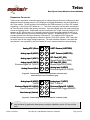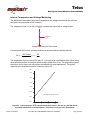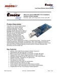
1
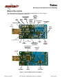
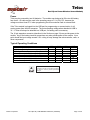
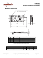
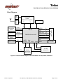
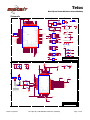
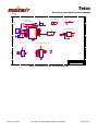
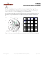
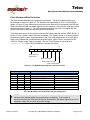
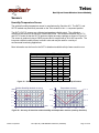
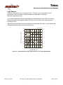
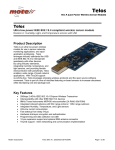
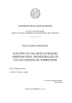
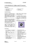
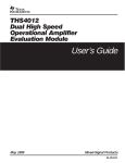
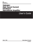
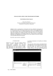
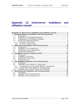
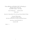
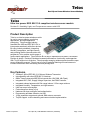
Telos
Rev B (Low Power Wireless Sensor Module)
Telos
Ultra low power IEEE 802.15.4 compliant wireless sensor module
Revision B : Humidity, Light, and Temperature sensors with USB
Product Description
Telos is an ultra low power wireless module
for use in sensor networks, monitoring
applications, and rapid application
prototyping. Telos leverages industry
standards like USB and IEEE 802.15.4 to
interoperate seamlessly with other devices.
By using industry standards, integrating
humidity, temperature, and light sensors,
and providing flexible interconnection with
peripherals, Telos enables a wide range of
mesh network applications. Telos Revision B is a drop-in replacement for Moteiv’s successful
Revision A design. Revision B includes increased performance, functionality, and expansion.
With TinyOS support out-of-the-box, Telos leverages emerging wireless protocols and the open
source software movement. Telos is part of a line of modules featuring on-board sensors to
increase robustness while decreasing cost and package size.
Key Features
•
•
•
•
•
•
•
•
•
•
•
•
250kbps 2.4GHz IEEE 802.15.4 Chipcon Wireless Transceiver
Interoperability with other IEEE 802.15.4 devices
8MHz Texas Instruments MSP430 microcontroller (10k RAM, 48k Flash)
Integrated ADC, DAC, Supply Voltage Supervisor, and DMA Controller
Integrated onboard antenna with 50m range indoors / 125m range outdoors
Integrated Humidity, Temperature, and Light sensors
Ultra low current consumption
Fast wakeup from sleep (<6µs)
Hardware link-layer encryption and authentication
Programming and data collection via USB
16-pin expansion support and optional SMA antenna connector
TinyOS support : mesh networking and communication implementation
Moteiv Corporation
Telos (Rev B) : PRELIMINARY Datasheet (12/5/2004)
Page 1 of 28
Telos
Rev B (Low Power Wireless Sensor Module)
Table of Contents
Module Description .......................................................................................................................3
Power ....................................................................................................................................4
Typical Operating Conditions ................................................................................................4
Mechanical Characteristics ...................................................................................................5
Block Diagram.......................................................................................................................6
Schematic .............................................................................................................................7
Microprocessor .............................................................................................................................9
Description ............................................................................................................................9
Typical Operating Conditions ................................................................................................9
PC Communication ...............................................................................................................9
Programming.......................................................................................................................10
Block Diagram.....................................................................................................................12
Radio...........................................................................................................................................13
Description ..........................................................................................................................13
Typical Operating Conditions ..............................................................................................14
Measured Output Power .....................................................................................................14
Antenna.......................................................................................................................................15
Internal Antenna..................................................................................................................15
Internal Antenna without Battery Pack ................................................................................16
Internal Antenna with Battery Pack .....................................................................................16
Radiation Pattern ................................................................................................................17
SMA Connector...................................................................................................................18
External Flash .............................................................................................................................19
Typical Operating Conditions ..............................................................................................19
Flash Hardware Write Protection ........................................................................................20
Sensors.......................................................................................................................................21
Humidity/Temperature Sensor ............................................................................................21
Light Sensors ......................................................................................................................22
Expansion Connector..........................................................................................................23
Internal Temperature and Voltage Monitoring.....................................................................25
General Information ....................................................................................................................26
Document History................................................................................................................26
Product Status Definitions...................................................................................................26
Disclaimer ...........................................................................................................................27
Address Information ............................................................................................................28
Headquarters ......................................................................................................................28
Moteiv Corporation
Telos (Rev B) : PRELIMINARY Datasheet (12/5/2004)
Page 2 of 28
Telos
Rev B (Low Power Wireless Sensor Module)
Module Description
The Telos module is a low power “mote” with integrated sensors, radio, antenna,
microcontroller, and programming capabilities.
User
Button
USB Transmit LED
Humidity
Photosynthetically
Temperature
Active Radiation
Sensor
Sensor
(optional)
Reset
(optional)
Total Solar
Button
Radiation
6-pin expansion
Sensor
connector
(optional)
10-pin expansion
connector
USB
Connector
Internal
Antenna
USB Receive LED
LEDs
USB
Microcontroller
Digital switch
Isolating USB from
microcontroller
JTAG
connector
Texas Instruments
MSP430 F1611
microcontroller
CC2420
Radio
SMA
Antenna
Connector
(optional)
48-bit silicon
serial ID
2-pin SVS
connector
USB
Flash (2kB)
32kHz
oscillator
ST Code
Flash (1MB)
Figure 1 : Front and Back of the Telos module
Moteiv Corporation
Telos (Rev B) : PRELIMINARY Datasheet (12/5/2004)
Page 3 of 28
Telos
Rev B (Low Power Wireless Sensor Module)
Power
Telos may be powered by two AA batteries. The module was designed to fit the two AA battery
form factor. AA cells may be used in the operating range of 2.1 to 3.6V DC, however the
voltage must be at least 2.7V when programming the microcontroller flash or external flash.
If the Telos module is plugged into the USB port for programming or communication, it will
receive power from the host computer. The mote operating voltage when attached to USB is
3V. If Telos will always be attached to a USB port, no battery pack is necessary.
The 16-pin expansion connector (described in the Section on page 19) can provide power to the
module. Any of the battery terminal connections may also provide power to the module. At no
point should the input voltage exceed 3.6V—doing so may damage the microcontroller, radio, or
other components.
Typical Operating Conditions
Supply voltage
Supply voltage during flash memory programming
Operating free air temperature
Current Consumption: MCU on, Radio RX
Current Consumption: MCU on, Radio TX
Current Consumption: MCU on, Radio off
Current Consumption: MCU idle, Radio off
Current Consumption: MCU standby
MIN
2.1
2.7
-40
NOM
21.8
19.5
1800
54.5
5.1
MAX
3.6
3.6
85
23
21
2400
1200
21.0
UNIT
V
V
o
C
mA
mA
µA
µA
µA
Caution!
ESD
sensitive
device.
Precaution should be used when handling
the device in order to prevent permanent
damage.
Moteiv Corporation
Telos (Rev B) : PRELIMINARY Datasheet (12/5/2004)
Page 4 of 28
Telos
Rev B (Low Power Wireless Sensor Module)
Mechanical Characteristics
O n -b o a rd a n t e n n a ; d o n o t c o v e r
w it h c o n d u c t in g m a t e ria ls
3
6
1.267
1
4
5
2
.513
2.580
3.163
.256
Tag
1
2
3
4
5
6
X
Y
Size
Notes
0.183 0.099 Ø 0.090 Mounting hole, do not use metal fixture
2.454 0.099 Ø 0.090 Mounting hole
2.454 1.151 Ø 0.090 Mounting hole
0.755 0.162 Ø 0.066 Pin 1 of 10-pin 0.1in rect IDC connector
1.099 0.163 Ø 0.066 Pin 1 of 6-pin 0.1in rect IDC connector
2.139 0.909 Ø 0.034 Pin 1 of 8-pin 2mm rect JTAG connector
Figure 2 : Physical dimensions of Telos Revision B.
All units are in inches unless otherwise noted.
Width
Length
Height (without battery pack and SMA antenna)
Moteiv Corporation
MIN
1.24
2.55
0.24
NOM
1.26
2.58
0.26
Telos (Rev B) : PRELIMINARY Datasheet (12/5/2004)
MAX
1.29
2.60
0.27
UNIT
in
in
in
Page 5 of 28
Telos
Rev B (Low Power Wireless Sensor Module)
Block Diagram
PCB
Antenna
CC2420 Radio
2.4 GHz
IEEE 802.15.4 compliant
SMA
Coax
SPI
6
4
Power
PAR
Sensor
ADC[4]
TSR
Sensor
ADC[5]
JTAG 8-pin
2mm IDC header
JTAG
SPI[0]
I/O
P1[0,3,4]
P4[1,5,6]
TI MSP430 Microcontroller
UART[0]
2
I2C[0]
2
ADC[0-3,6-7]
6
GPIO
4
Reset
10-pin + 6-pin
IDC header
Humidity
Temperature
Sensor
Silicon Serial ID
1-wire
I/O
User
UART[1] Reset
P1.1/P2.2 TCK I2C[0]
2
2
Power
7
SVSin
4
RX/TX RTS/DTR
JTAG
USB 2.0
UART/RS232
Functionality
SVS 2-pin
IDC header
SPI[0] SVSout
Write Protection
ST Flash
1024k (2.7V)
Figure 3 : Functional Block Diagram of the Telos Module, its components, and buses
Moteiv Corporation
Telos (Rev B) : PRELIMINARY Datasheet (12/5/2004)
Page 6 of 28
Telos
Rev B (Low Power Wireless Sensor Module)
Schematic
5
4
3
1
2
R1
S E N S OR S
RESET
LED2
P5.5/SMCLK
49
45
P5.0/STE1
44
P6.7/A7/DAC1/SVSIN
Vref+
8
XIN
9
XOUT/TCLK
10
43
P4.6/TB6
42
P4.5/TB5
41
P4.4/TB4
40
39
F L A SH _ H O L D
R A D I O _ R E S ET
R A D I O _ V R EF_ EN
F L A SH _ C S
Pr e v Fl a s h Pwr
RADIO_CS
37
R A DIO_SFD
P4.0/TB0
36
P3.7/URXD1
35
UART1RX
P3.6/UTXD1
34
UART1TX
P3.5/URXD0
33
UART0RX
D
L2
1
2
F Be a d 2 4 0 - 1 0 3 5 - 1
OPTI ONAL
R 12
1 0 0 k 1%
1
2
2
UART0RX
4
4
UART0TX
6
6
I 2 C _ SC L
8
8
I 2 C _ SD A
3
5
7
7
9
9
10
10
SW2
A DC3
U s e r IN T
2
1
EVQ-P2K02Q
G IO 0
ACL K
U 28
C9
0 .1 u
0 open
A DC6
1 1
DAC0
G IO 2
3
Ti me r A Ca p t u r e 3
U s e r IN T
5 5
A DC7
DAC1 / SVSi n
G IO 3
DMAE0
RESET
6
2
2
4
4
6
R 15
M O U N T ING HO L ES
S V S out
0 open
6 pin Header
1
P3.4/UTXD0
J TA G
32
U8
J10
TDO
TDO
1
1
2
2
TDI
TDI
3
3
4
4
TMS
TMS
5
5
6
6
TCK
TCK
7
7
8
8
J11
DV CC
DV CC
D4
S
Q
W
Vss
L ED 1
2
D5
U5
1
2
3
4
R7
1
R e d C l e a r - 404-1017-1-ND
470
F L A SH
F L A SH _ C S
R A D IO_ SO
P_DVCC
B
J12
No n p l a t e d
n e ar ant enna
L EDS
RESET
8 p i n H e a d e r - 2m m
R2
2.2k
Vcc
HOLD
C
D
8
7
6
5
R8
1
DV CC
F L A SH _ H OL D
R A D I O_ SC L K
RADIO_SI
L ED 2
2
G r e e n C lear - 4 0 4 - 1 0 2 1 - 1 - N D
220
C6
0 .1 u
R9
D6
1
L ED 3
2
B l u e C le a r - 4 0 4 - 1 0 2 8 - 1 - N D
100
S E R IA L ID
A
U9
1Wire
1
I/O Vcc
GND
2
3
DV CC
Title
Size
B
D S2 4 1 1
D a te:
4
3
2
4
3
2
Tel o s
D o c u ment Number
R ev
B
(c ) Co p y r i g h t 2004: UC B er k el ey
Wednesday, September 29, 2004
S h eet
1
of
3
1
1
C 64
1 0 u F L o w E SR < 5 o h m
NC
37
39
38
XOSC16_Q2
CC24K_DVDD
40
CC24K_DVDD3
41
VREG_EN
VREG_OUT
42
44
43
45
R_BIAS
VREG_IN
AVDD_IF1
47
46
ATEST2
AVDD_XOSC16
32
R A D I O_ SC L K
CSn
31
RADIO_CS
FIFO
30
R A D IO _ G IO 0
FIFOP
29
CCA
28
R A D IO _ G IO 1
AVDD_SW
SFD
27
R A DIO_SFD
DVDD1.8
26
C C 2 4 K _ D VD D
DVDD3.3
25
C C 2 4 K _ D VD D 3
13
B
DSUB_CORE
NC
2 . 4 GHz ma t c h i n g n e t wo r k
CC2420
PKT_INT
24
NC
DGND
NC
12
RESETn
11
DSUB_PADS
RF_N
21
C 81
0 . 5 p + / - 0 .2 5 p n p 0
RADIO_SI
SCLK
GND
DGUARD
7 .5 n 5 %
a t 2 . 4 GHz
ma t c h e d t o 5 0 o h ms
C
R 4 76
1 0k
R A D IO_ SO
8
10
2
TXRX_SWITCH
C C 2 4 K _ D VD D 3
R 4 74
10k
C C 2 4 K _ D VD D
9
DGND_GUARD
1
RF_P
20
L81
u s e 50 ohm t r ac es
GND
19
1
33
AVDD_RF1
5
7
5 . 6 p 1 0 % x5 r
SI
4
6
DVDD_ADC
1
1
5 . 6 p + / - 0 .2 5 p n p 0
34
AVDD_ADC
2
L61
7 .5 n 5 %
SO
NC
C 71
DVDD_RAM
AVDD_PRE
18
3
2
AVDD_VCO
17
L62
5 .6 n 5 %
C C 2 4 K _ D VD D 3
36
35
16
2
C C 2 4 K_ AVD D
NC
3
D
C 3 81
2 2 p 5% np0
1 6 MH Z - 1 6pf
GND_EX
AVDD_IF2
0 . 5 p + / - 0 .2 5 p n p 0
C 73
C391
2 2 p 5% np0
X1
VCO_GAURD U 10
2
AVDD_RF2
C 61
ATEST1
48
1
AVDD_CHP
49
15
CC24K_AVDD
A2
SMA
1
C
14
1
2
3
GND
GND
GND
RF GND
5
4
3
2
A1
C C 2 4 2 0 _ PC B_ AN T
DVCC
C8
0 .1 u
R 4 73
1m
R 4 75
0
R 4 51
43k 1%
L3
2
F Be a d 2 4 0 - 1 0 3 5 - 1
C7 i s o l a t i o n
0 .1 u
C C 2 4 K _ D VD D 3 1
R A D I O _ V R EF_ EN
XOSC16_Q1
C 87
0 .1 u
23
C 86
68p
22
C 85
0 .1 u
C 84
10n
CC24K_AVDD
C 83
68p
CC24K_AVDD
C C 2 4 K _ D VD D
D
B
C
R4
4 7 0k
U S E R S W I TC H
R14
1 0 p i n H e a d e r - 0 .1 "
UART1RX
RESET
2
DV CC
M25P80
C 82
68p
C3
10uF
EVQ-P2K02Q
5
DV CC
5
DV CC
R E S E T S W I TC H
RADIO_SI
C C 2 4 K_ AVD D
DVCC
C2
0 . 1u
1
A DC1
R A D IO _ SO
5
DV CC
C1
0 .1 u
D3
S1087-01 Photodiode
0 open
R A D I O_ SC L K
A
2SVS out
PW R _ C O NN
V C C in
3
G IO 1
UART0TX
31
P3.2/SOMI0
P3.0/STE0
P3.1/SIMO0/SDA
29
30
RADIO_SO
I2C_SDA RADIO_SI
P2.7/TA0
28
27
P2.6/ADC12CLK/DMAE0
GIO3
UserINT
26
P2.5/Rosc
25
P2.4/CA1/TA2
1Wire
24
P2.3/CA0/TA1
23
GIO2
P2.1/TAINCLK
P2.0/ACLK
20
19
18
17
HUM_SDA
HUM_PWR
HUM_SCL
B
GIO0
P1.4/SMCLK
P1.7/TA2
P1.3/TA2
16
P1.6/TA1
15
P1.5/TA0
R A D I O _ G IO 0
R A D I O _ G IO 1
P2.2/CAOUT/TA0/BSLRX
TI_MSP430_F1611
I2C_SCL RADIO_SCLK
P1.1/TA0/BSLTX
P3.3/UCLK0/SCL
38
P4.1/TB1
P1.2/TA1
1
R 16
P4.3/TB3
13
H U M_ S D A
A DC0
A DC2
P4.2/TB2
14
H U M_ S C L
2
A DC5
AV CC
Vref-/VeREF-
P_DVCC
2
SW1
P1.0/TACLK
UART1TX
3
SDA
U2
VeREF+
P_DVCC
1
2 p i n H e a d e r - 2m m
E X P A N S ION
11
UART1TX
SCLK
OPTI ONAL
R 11
1 0 0 k 1%
12
22
PKT_INT
P4.7/TBCLK
MCU
21
3 2kHz
R5
5 .1 M
6
7
GIO1
A DC7
S V S in 1
V C C in
1
P5.1/SIMO1
S V S in
U7
V C C in
1
P6.5/A5
P6.6/A6/DAC0
2
1
4
5
1
-
1
52
51
50
P5.6/ACLK
54
53
XT2IN
XT2OUT
P5.7/TBoutH/SVSOUT
TDI
TDO/TDI
55
56
TCK
TMS
57
58
46
A DC6
+
1
LED3
SVSout
TDI
TDO
TCK
RESET
TMS
ADC0
P6.0/A0
RST/NMI
59
60
61
47
P5.2/SOMI1
1
C
P6.1/A1
P5.3/UCLK1
P6.4/A4
UART1RX
2
P6.2/A2
P6.3/A3
3
D AC0
GND
3
63
P5.4/MCLK
2
A DC4
DVcc
VCC
GND
D2
S1087 Photodiode
L ED 1
10k
SHT11
OPTI ONAL
A DC4
A DC3
A DC5
X0
U0
1
C5
0 .1 u
48
1
U4
R 10
U3
HUMI DI TY/
TEMP SENSOR
4
62
64
AVcc
DV CC
P O WE R
H U M_ P W R
0 .1 u
AVss
D
DVss
AVCC
C4
ADC1
ADC2
1 0 0k
C C 2 4 K_ AVD D
C C 2 4 K _ D VD D
C C 2 4 K _ D VD D
R A D I O _ R E SET
R472
1m
C C 2 4 K _ D VD D 3
A
A
Title
Size
B
D a te:
5
Moteiv Corporation
4
3
2
Telos (Rev B) : PRELIMINARY Datasheet (12/5/2004)
Tel o s
CC2420 802.15.4 Wi r el es s Rad i o
D o c u ment Num ber
R ev
B
(c ) Co p y r i g h t 2004: UC B er k el ey
Wednesday, September 29, 2004
S h eet
2
of
3
1
Page 7 of 28
Telos
Rev B (Low Power Wireless Sensor Module)
5
4
3
2
U S B P OW E R F I L T E R
1
MOTE POWER
USB INTERFA CE
1
1
27
U _ VCC
8
USBDM
7
USBDP
1 .5k
5
4
27
X3
GND
3
E EC S
EESK
EEDATA
R 32
1m
2
1
6 M r e s o n a to r
28
32
1
2
31
25
24
23
22
21
20
19
18
TXDEN
TXLED#
RXLED#
16
12
11
PWRCTL
PWREN#
SLEEP#
14
15
10
RSTOUT#
RESET#
XTOUT
EECS
EESK
EEDATA
TEST
FT232BM
P_DVCC
1
V C C in
2
V C C in
1
13
30
3
26
VCC
TXD
RXD
RTS#
CTS#
DTR#
DSR#
DCD#
RI#
XTIN
P_DVCC
GND
Vout
Vin
2
L L SD 1 0 3 A
R 29
1 0k
C25
10u
D
U _ VCC
U 25
T C 5 5 R P3 3
C 22
0 . 1u
VCCIO
3V3OUT
U SBU SB+
R 24
R 23
VCC
6
R 22
27
3
C 24
0 . 1u
TXD
RXD
RTS
DSR
D TR
U S B ID E N T I F I C A T ION EEPROM
D20
R 25
D CD
RI
2
1 00
1
E EC S
1
CS
VCC
8
EESK
2
SK
NC
7
EEDATA
R 27
3
DIN
NC
6
4
DOUT
GND
5
G r e e n C lear - 4 0 4 - 1 0 2 1 - 1 - N D
D21
R 26
2
1 00
U 23
U _ V C C 3 .3
1
R e d C l e a r - 404-1017-1-ND
2.2k
GND
2
GND
3
AGND
4
3
2
9
4
U SB A
C
U 20
AVCC
0 . 1u
C 21
33n
U _ V C C 3 .3
R 20
470
U_AVCC
C 23
0 . 1u
U _ VCC
C
9 3 C46
R28
U _ VCC
17
C20
U 22
P_DVCC
U _ VCC
2
F Be a d 2 4 0 - 1 0 3 5 - 1
1
29
L20
D
D 22
U _ VCC
Used for Reading Serial / Programming
Connects and Powered via USB
10k
I/O B UFFER
R E S E T S E QU E N C E R E C OGN ITION
1Y
6
P_DVCC
UART1TX
7
5
2OE
2A
2Y
3
UART1RXUART1RX
RXD
D TR
RTS
3
1
23
24
22
VCC
DV CC
TD O
TDI
TMS
TCK
TCK
R ESET
R 30
10k
TCK
SDA
SCLK
RST
A0
A1
21
4
P_DVCC
B
A D G 7 1 5 BR U
D8 1 9
D7 1 7
TDO
D6 15
TDI
D5 13
TMS
D4 12
TCK
D3 10
TC K
8
D2
RESET
6
D1
GND
1OE
1A
VSS
1
2
S8
S7
S6
S5
S4
S3
S2
S1
4
DV CC
8
P_DVCC
TXD
Gnd
UART1TX
D CD
RI
DSR
D TR
N C7W Z126
Vcc
U 29
U 27
20
18
16
14
11
9
7
5
2
DV CC
DVCC
DVCC
B
A
A
Title
Size
B
D a te:
5
4
3
2
Tel o s
USB In t er f ac e
D o c u ment Number
R ev
B
(c ) Co p y r i g h t 2004: UC B er k el ey
Wednesday, September 29, 2004
S h eet
3
of
3
1
Figure 4 : Schematics for the Telos module (Rev B)
Moteiv Corporation
Telos (Rev B) : PRELIMINARY Datasheet (12/5/2004)
Page 8 of 28
Telos
Rev B (Low Power Wireless Sensor Module)
Microprocessor
Description
The low power operation of the Telos module is due to the ultra low power Texas Instruments
MSP430 F1611 microcontroller featuring 10kB of RAM, 48kB of flash, and 128B of information
storage. This 16-bit RISC processor features extremely low active and sleep current
consumption that permits Telos to run for years on a single pair of AA batteries. The MSP430
has an internal digitally controlled oscillator (DCO) that may operate up to 8MHz. The DCO
may be turned on from sleep mode in 6µs, however 292ns is typical at room temperature.
When the DCO is off, the MSP430 operates off an eternal 32768Hz watch crystal. Although the
DCO frequency changes with voltage and temperature, it may be calibrated by using the 32kHz
oscillator.
In addition to the DCO, the MSP430 has 8 external ADC ports and 8 internal ADC ports. The
ADC internal ports may be used to read the internal thermistor or monitor the battery voltage.
A variety of peripherals are available including SPI, UART, digital I/O ports, Watchdog timer,
and Timers with capture and compare functionality. The F1611 also includes a 2-port 12-bit
DAC module, Supply Voltage Supervisor, and 3-port DMA controller.
The features of the MSP430 F1611 are presented in detail in the Texas Instruments
MSP430x1xx Family User’s Guide available at http://ti.com/msp430.
Typical Operating Conditions
Supply voltage during program execution
Supply voltage during flash memory programming
Operating free air temperature
Low frequency crystal frequency
Active current at Vcc = 3V, 1MHz
Sleep current in LPM3 Vcc = 3V, 32.768kHz active
Wake up from LPM3 (low power mode)
MIN
1.8
2.7
-40
NOM
32.768
500
2.6
MAX
3.6
3.6
85
600
3.0
6
UNIT
V
V
o
C
kHz
µA
µA
µs
PC Communication
Telos uses a USB controller from FTDI to communicate with the host computer. In order to
communicate with the mote, the FTDI drivers must be installed on the host. FTDI provides
drivers for Windows, Linux, BSD, Macintosh, and Windows CE. These drivers are included on
the Moteiv CD shipped with your order. Windows users will need the Virtual Com Port (VCP)
drivers. They may also be downloaded from FTDI’s website at: http://www.ftdichip.com/
After installing the driver, Telos appears as a COM port in Windows’ device manager (or as a
device in /dev in Linux, OSX, and BSD). Multiple Telos motes may be connected to a single
computer’s USB ports at the same time. Each mote will receive a different COM port identifier.
In the example below, one Telos is connected and assigned COM6 “USB Serial Port”.
An application may read from Telos by opening the COM port assigned to the Telos mote.
Telos communicates with the host PC through USART1 on the TI MSP430.
Moteiv Corporation
Telos (Rev B) : PRELIMINARY Datasheet (12/5/2004)
Page 9 of 28
Telos
Rev B (Low Power Wireless Sensor Module)
Figure 5 : Device Manager showing Telos installed as COM6
The motelist command line utility lists all of the Telos motes currently connected to a
computer. This utility optionally lists previously connected motes that the system has cached.
Invoke motelist with the -h option for more information.
> motelist
Reference CommPort
Description
---------- ---------- ---------------------------------------M4MXVA4Y
COM6
Telos (Rev B 2004-09-27)
NOTE: Telos (Revision B) uses an I2C digital switch to prevent unwanted conventional
serial port signals from reaching the TI microcontroller. The I2C protocol must be
implemented and sent over the RTS and DTR lines in order to obtain direct access
between the Telos and USB controller. The UART lines do not use the I2C switch allowing
direct communication (but not programming or JTAG) without additional software.
Programming
The Telos module is programmed through the onboard USB connector. A modified version of
the MSP430 Bootstrap Loader, msp430-bsl, programs the microcontroller’s flash. Telos has a
unique hardware circuit that prevents the mote from spuriously resetting. This hardware circuit
makes it necessary to have a special sequence sent to the module in order to program it.
By invoking msp430-bsl, verify you have the patched BSL by looking for the “telos” keyword.
Version 1.39-telos-6 or later is required for Telos (Rev B).
> msp430-bsl
MSP430 Bootstrap Loader Version: 1.39-telos-6
Use -h for help
Moteiv Corporation
Telos (Rev B) : PRELIMINARY Datasheet (12/5/2004)
Page 10 of 28
Telos
Rev B (Low Power Wireless Sensor Module)
To communicate with Telos, the MSP430 Bootstrap Loader requires a set of options to provide
the proper signals to the microcontroller to initiate programming. For convenience, the options
have been folded into a single Telos (Revision B) flag:
--telosb
To program a Telos module on COM3 (or /dev/ttyUSB2 in Linux) with an application image
named app.ihex, invoke the MSP430 Bootstrap loader with the following options.
> msp430-bsl --telosb -c 2 -r -e -I -p app.ihex
MSP430 Bootstrap Loader Version: 1.39-telos-6
Mass Erase...
Transmit default password ...
Invoking BSL...
Transmit default password ...
Current bootstrap loader version: 1.61 (Device ID: f16c)
Changing baudrate to 38400 ...
Program ...
2742 bytes programmed.
Reset device ...
If you are using TinyOS, it has support for programming Telos. After compiling your application,
you may install it with the following command
> make telosb install.x bsl,n
Where x is the 16-bit address assigned to the mote and n is the COM port that Telos is
currently using. Note that not including “bsl” or “bsl,n” will program automatically using the
bsl to the first Telos mote found on the USB bus using the motelist command.
For more information about the options in the MSP430 Bootstrap loader, invoke msp430-bsl
with the -h option to display the help information.
Motelist and msp430-bsl are available from Moteiv Corporation at http://www.moteiv.com in
the “Support” section.
NOTE: msp430-bsl starts counting from 0, but COM ports in Windows start counting at 1.
If Telos is connected to COM3 in Windows, you must program it using “-c 2” or “bsl,2”
when invoking msp430-bsl. In Linux, Telos will appear as /dev/ttyUSB2 and may be
programmed using “-c 2” or “bsl,2”.
Moteiv Corporation
Telos (Rev B) : PRELIMINARY Datasheet (12/5/2004)
Page 11 of 28
Telos
Rev B (Low Power Wireless Sensor Module)
Block Diagram
32kHz
Oscillator
Flash
ACLK
System
Clock
SMCLK
RAM
12-bit ADC
8 Channels
<10µs Conv
12-bit DAC I/O Port 1/2 I/O Port 3/4 I/O Port 5/6
16 I/Os
16 I/Os
8 I/Os
2 Channels
Interrupts
MCLK
16-bit bus
CPU
16 bit
16 reg
multiply
DMA
Controller
3 Channels
Watchdog
Timer
15/16 bit
Timer A
3 CC reg
Timer B
7 CC reg
Comparator
A
USART0
UART
SPI
I 2C
USART1
UART
SPI
CC2420 Radio
Interrupts & SPI
PC
UART via USB
Figure 6 : Block diagram of the TI MSP430 microcontroller and its connection to other peripherals
in the Telos module
Moteiv Corporation
Telos (Rev B) : PRELIMINARY Datasheet (12/5/2004)
Page 12 of 28
Telos
Rev B (Low Power Wireless Sensor Module)
Radio
Description
Telos features the Chipcon CC2420 radio for wireless communications. The CC2420 is an
IEEE 802.15.4 compliant radio providing the PHY and some MAC functions. With sensitivity
exceeding the IEEE 802.15.4 specification and low power operation, the CC2420 provides
reliable wireless communication. The CC2420 is highly configurable for many applications with
the default radio settings providing IEEE 802.15.4 compliance. Features and usage of the
CC2420 is available in Chipcon’s datasheet at http://www.chipcon.com
The CC2420 is controlled by the TI MSP430 microcontroller through the SPI port and a series of
digital I/O lines and interrupts (see the Schematics on page 7 for more information). The radio
may be shut off by the microcontroller for low power duty cycled operation.
The CC2420 has programmable output power. Common CC2420 register values and their
corresponding current consumption and output power are shown in Figure 7.
PA_LEVEL
31
27
23
19
15
11
7
3
Current Consumption [mA]
TXCTRL register Output Power [dBm]
0xA0FF
0
17.4
0xA0FB
-1
16.5
0xA0F7
-3
15.2
0xA0F3
-5
13.9
0xA0EF
-7
12.5
0xA0EB
-10
11.2
0xA0E7
-15
9.9
0xA0E3
-25
8.5
Figure 7 : Output power configuration for the CC2420
The CC2420 provides a digital received signal strength indicator (RSSI) that may be read any
time. Additionally, on each packet reception, the CC2420 samples the first eight chips,
calculates the error rate, and produces a link quality indication (LQI) value with each received
packet. A mapping from RSSI to the RF level in dBm is shown in Figure 8.
Figure 8 : Received Signal Strength Indicator mapping to RF Power [dBm]
Moteiv Corporation
Telos (Rev B) : PRELIMINARY Datasheet (12/5/2004)
Page 13 of 28
Telos
Rev B (Low Power Wireless Sensor Module)
Typical Operating Conditions
Supply voltage during radio operation (Vreg on)
Operating free air temperature
RF frequency range
Transmit bit rate
Nominal output power
Programmable output power range
Receiver sensitivity
Current consumption: Radio transmitting at 0 dBm
Current consumption: Radio receiving
Current consumption: Radio on, Oscillator on
Current consumption: Idle mode, Oscillator off
Current consumption: Power Down mode, Vreg off
Voltage regulator current draw
Radio oscillator startup time
MIN
2.1
-40
2400
250
-3
-90
13
NOM
MAX
3.6
85
2483.5
250
0
40
-94
17.4
19.7
365
20
1
29
860
20
580
UNIT
V
o
C
MHz
kbps
dBm
dBm
dBm
mA
mA
µΑ
µΑ
µΑ
µΑ
µs
Measured Output Power
The RF output power of the Telos module from the CC2420 radio is shown in Figure 9. For this
test, the Telos module is transmitting at 2.405GHz (IEEE 802.15.4 channel 11) using the OQPSK modulation with DSSS. The CC2420 programmed output power is set to 0 dBm. The
measured output power of the entire modulated spectrum is 2.4 dBm.
0
RWB: 100 kHz
VWB: 100 kHz
Sweep: 50ms
−5
−10
Output power (dBm)
−15
−20
−25
−30
−35
−40
−45
−50
2.4
2.401
2.402
2.403
2.404
2.405
2.406
Frequency (GHz)
2.407
2.408
2.409
2.41
Figure 9 : Measured RF output power over the modulated spectrum from the Telos module
Moteiv Corporation
Telos (Rev B) : PRELIMINARY Datasheet (12/5/2004)
Page 14 of 28
Telos
Rev B (Low Power Wireless Sensor Module)
Antenna
Telos has two antenna options—and internal antenna built into the module and an external SMA
connector for connecting to external antennas. By default, Telos is shipped with the internal
antenna enabled. If an application requires an external antenna or a different directional pattern
than the internal antenna, an SMA connector may be installed and an antenna may be
connected directly to Telos’ SMA female connector.
In order to switch between the internal antenna and the SMA connector, the capacitor at C73
must be moved from the two left pads to the two right pads connecting the radio to the SMA
connector. This process may be completed quickly with a heat gun and tweezers by sliding the
capacitor over to the adjacent pad once the solder begins to melt.
To Internal
Antenna
To SMA
Connector
Figure 10 : Moving C73 to select between the internal antenna and the SMA connector
Internal Antenna
Telos’ internal antenna is an Inverted-F microstrip design protruding from the end of the board
away from the battery pack. The Inverted-F antenna is a wire monopole where the top section
is folded down to be parallel with the ground plane. Although not a perfect omnidirectional
pattern, the antenna may attain 50-meter range indoors and upwards of 125-meter range
outdoors. Measurements of the internal antenna’s performance with and without a battery pack
are show in Figure 11 and Figure 12. Approximate radiation patterns for the Inverted-F antenna
as provided by Chipcon AS are shown in Figure 13 and Figure 14.
Moteiv Corporation
Telos (Rev B) : PRELIMINARY Datasheet (12/5/2004)
Page 15 of 28
Telos
Rev B (Low Power Wireless Sensor Module)
Internal Antenna without Battery Pack
2004/11/25 Thr 14:44:06
CH2 S11
SMITH(R+jX)
FS
0
1.000
MKR 3: 2.483 958 333GHz
65.166
4.083
−5
1
−10
Cor
4
−15
Log(|S11|) (dB)
2
3
2
3
−20
−25
−30
−35
1
−40
1:2.400 000GHz
2:2.450 000GHz
3:2.483 958GHz
40.014
39.757
65.041
START 2.3GHz
-40.598
-4.623
4.227
[ 10.00 dBm]
1.633pF
14.050pF
270.843pH
STOP 2.55GHz
1:
2:
3:
−45 4:
2.400 GHz
2.450 GHz
2.485 GHz
2.500 GHz
−50
2.3
2.325
−7.40 dB
−16.58 dB
−16.58 dB
−12.50 dB
2.35
2.375
2.4
2.425
2.45
2.475
2.5
2.525
2.55
Frequency (GHz)
Figure 11 : S11 measurements for the internal inverted-F antenna when no battery pack is present
Internal Antenna with Battery Pack
2004/11/25 Thr 14:49:13
CH2 S11
SMITH(R+jX)
FS
0
1.000
MKR 3: 2.483 958 333GHz
57.265
7.168
−5
1
−10
Cor
Log(|S11|) (dB)
−15
3
4
2
−20
3
−25
−30
2
−35
−40
1
1:2.400 000GHz
2:2.450 000GHz
3:2.483 958GHz
START 2.3GHz
38.610
34.763
57.205
-49.225
-8.204
7.146
[ 10.00 dBm]
1.347pF
7.917pF
457.900pH
STOP 2.55GHz
1:
2:
3:
−45 4:
2.400 GHz
2.450 GHz
2.485 GHz
2.500 GHz
−50
2.3
2.325
−5.10 dB
−13.27 dB
−20.92 dB
−12.24 dB
2.35
2.375
2.4
2.425
2.45
2.475
2.5
2.525
2.55
Frequency (GHz)
Figure 12 : S11 measurements for the internal inverted-F antenna with battery pack underneath
Moteiv Corporation
Telos (Rev B) : PRELIMINARY Datasheet (12/5/2004)
Page 16 of 28
Telos
Rev B (Low Power Wireless Sensor Module)
Radiation Pattern
Figure 13 : Radiated pattern of the Inverted-F antenna with horizontal mounting (from Chipcon AS)
Figure 14 : Radiated pattern of the Inverted-F antenna with vertical mounting (from Chipcon AS)
Moteiv Corporation
Telos (Rev B) : PRELIMINARY Datasheet (12/5/2004)
Page 17 of 28
Telos
Rev B (Low Power Wireless Sensor Module)
SMA Connector
The SMA connector is a surface mount female coax connector for attaching an external
antenna. The default Telos configuration does not include the SMA connector. The connector
may be purchased separately from Digikey (http://www.digikey.com). The manufacturer’s part
number is 901-144 from Amphenol RF (Digikey part number ARF1205-ND).
The performance of the SMA connector is independent of the presence of the battery pack. The
S11 network analyzer measurements for the SMA connector performance are shown in Figure
15.
2004/11/25 Thr 13:37:58
CH1 S11
SMITH(R+jX)
FS
1.000
MKR 3:
64.698
0
4
2.486 25GHz
3
−5
2
1
−10
Cor
−15
3
Log(|S11|) (dB)
2
1
−20
−25
−30
−35
−40
1:2.400 000GHz
2:2.450 000GHz
3:2.486 250GHz
START 2.3GHz
63.063
43.059
64.625
29.795
44.470
97.928
[ 10.00 dBm]
1.975nH
2.888nH
6.268nH
STOP 2.55GHz
1:
2:
3:
−45 4:
2.400 GHz
2.450 GHz
2.485 GHz
2.500 GHz
−50
2.3
2.325
−7.91 dB
−4.97 dB
−2.55 dB
−1.02 dB
2.35
2.375
2.4
2.425
2.45
2.475
2.5
2.525
2.55
Frequency (GHz)
Figure 15 : S11 measurements of the SMA connector (minimal variance with/without battery pack)
Moteiv Corporation
Telos (Rev B) : PRELIMINARY Datasheet (12/5/2004)
Page 18 of 28
Telos
Rev B (Low Power Wireless Sensor Module)
External Flash
Telos Revision B uses the ST M25P80 40MHz serial code flash for external data and code
storage. The flash holds 1024kB of data and is decomposed into 16 segments, each 64kB in
size. The flash shares SPI communication lines with the CC2420 transceiver. Care must be
taken when reading or writing to flash such that it is interleaved with radio communication,
typically implemented as a software arbitration protocol for the SPI bus on the microcontroller.
DVCC
U5
P 4.4
P _DVCC
USB Power
FLASH_CS
RADIO_SO
R29
10k
1
2
3
4
S
Q
W
Vss
Vcc
HOLD
C
D
8
7
6
5
DVCC
FLASH_HOLD
R ADIO_SCLK
RADIO_SI
P 4.7
M25P80
Figure 16 : External serial flash schematic
Typical Operating Conditions
Supply voltage during flash memory programming
Operating free air temperature
Erase/Programming cycles
Data Retention
Active current (READ)
Active current (WRITE/ERASE)
Standby current
Deep Power Down current
MIN
2.7
-40
NOM
8
1
MAX
3.6
85
100,000
20
4
20
50
10
UNIT
V
o
C
cycles
years
mA
mA
µA
µΑ
NOTE: The ST M25P-series of code flash always starts in the standby state. For low
power applications, the flash must be sent a command at boot time to place it in the deep
power down mode. If using TinyOS, the flash is automatically put into deep power down
mode and must be instructed to exit deep power down mode the first time the flash is
accessed. See the ST M25P80 datasheet for more information.
http://www.st.com/stonline/books/pdf/docs/8495.pdf
Moteiv Corporation
Telos (Rev B) : PRELIMINARY Datasheet (12/5/2004)
Page 19 of 28
Telos
Rev B (Low Power Wireless Sensor Module)
Flash Hardware Write Protection
The flash includes hardware write protection functionality. The write protection exists on a
sector basis as shown in Figure 18. The hardware write protection pin (Pin 3 of the M25P80
shown in Figure 16) only disables write protection when the module is powered by the USB port.
When connected to USB, the status register must be updated by removing the write protect and
block protect bits in Figure 17. The write protected segments may only be changed after the
module connected to USB and the write protect bit is cleared.
Telos ships with sector 15 (the upper sixteenth sector) write protected and the SRWD bit set. In
sector 15 is the “Golden Image” and factor metadata. The “Golden Image” is a factory program
image that includes network reprogramming so that Telos may always return to a known good
state, even if loaded with a malfunctioning program image. When Telos is connected to the
USB, the “Golden Image” may be changed. See the TinyOS Deluge documentation in
tinyos-1.x/docs of the TinyOS distribution included with Telos.
b7
SRWD
b0
0
0
BP2
BP1
BP0
WEL
WIP
Status Register
Write Protect
Block Protect Bits
Write Enable Latch Bit
Write In Progress Bit
Figure 17 : ST M25P80 Status Register contents (from ST).
Status Register Content
Memory Content (Sectors)
BP2 Bit BP1 Bit BP0 Bit Protected Area
Unprotected Area
0
0
0
None
All sectors (0-15)
0
0
1
Upper sixteenth (15)
Lower fifteen-sixteenths (0-14)
0
1
0
Upper eighth (14-15)
Lower seven-eighths (0-13)
0
1
1
Upper quarter (12-15)
Lower three-quarters (0-11)
1
0
0
Upper half (8-15)
Lower half (0-7)
1
0
1
All sectors (0-15)
None
1
1
0
All sectors (0-15)
None
1
1
1
All sectors (0-15)
None
Figure 18 : Write protection settings for the ST M25P80 flash.
Telos Rev B modules are shipped with the gray setting (001).
NOTE: When programming data to write protected segments of external flash, do not
disconnect the module before the programming is completely. If the module is
disconnected from the USB, the write may be interrupted or the status register may not be
updated to reflect the new write protection settings.
Moteiv Corporation
Telos (Rev B) : PRELIMINARY Datasheet (12/5/2004)
Page 20 of 28
Telos
Rev B (Low Power Wireless Sensor Module)
Sensors
Humidity/Temperature Sensor
The optional humidity/temperature sensor is manufactured by Sensirion AG. The SHT11 and
SHT15 models may be directly mounted on the Telos module in the U3 component position.
The SHT11/SHT15 sensors are calibrated and produce a digital output. The calibration
coefficients are stored in the sensor’s onboard EEPROM. The difference between the SHT11
and SHT15 model is that the SHT15 produces higher accuracy readings as shown in Figure 20.
The sensor is produced using a CMOS process and is coupled with a 14-bit A/D converter. The
low power relative humidity sensor is small in size and may be used for a variety of
environmental monitoring applications.
More information can be found in the SHT1x datasheet available at http://www.sensirion.com
Parameter
Humidity
Resolution
Repeatability
Range
Temperature
Resolution
MIN
TYP
MAX
Units
0.5
8
0.03
12
±0.1
0.03
12
%RH
Bit
%RH
%RH
0
Relative Humidity absolute accuracy
±4
o
±2 °C
SHT15
±2
0.01
0.02
14
Temperature accuracy
±3 °C
SHT11
±3
0.01
0.02
14
±0.1
±0.2
o
C
F
bit
o
Repeatability
C
o
F
Range
-40
123.8 oC
-40
254.9 oF
Figure 19 : Sensirion relative humidity and temperature performance specifications
%RH
±5
0.04
0.07
12
100
SHT15
±1
±0
0 10 20 30 40 50 60 70 80 90 100
%RH
±3.6 °F
SHT11
±1 °C
±5.4 °F
±1.8 °F
0 °C
0 °F
-40°C
-40°F
0°C
32°F
40°C
104°F
80°C
176°F
120°C
248°F
Figure 20 : Accuracy of Sensirion relative humidity and temperature sensors (courtesy Sensirion)
Moteiv Corporation
Telos (Rev B) : PRELIMINARY Datasheet (12/5/2004)
Page 21 of 28
Telos
Rev B (Low Power Wireless Sensor Module)
Light Sensors
A variety of light sensors may be used with Telos. Telos (rev A) has connections for two
photodiodes. Moteiv currently uses photodiodes from Hamamatsu Corporation
(http://www.hamamatsu.com)
If your mote is populated with light photodiodes, the default diodes are the S1087 for sensing
photosynthetically active radiation and the S1087-01 for sensing the entire visible spectrum
including infrared
Although these photodiodes from Hamamatsu have been tested with Telos, any photodiode with
similar physical dimensions may be used with Telos.
(Typ. Ta=25oû
C)
0.7
S1087-01
PHOTO SENSITIVITY (A/W)
0.6
0.5
QE=100 %
0.4
0.3
0.2
S1087
0.1
0
200
400
600
800
1000
WAVELENGTH (nm)
Figure 21 : Photo Sensitivity of the Light sensors on Telos (from Hamamatsu)
Moteiv Corporation
Telos (Rev B) : PRELIMINARY Datasheet (12/5/2004)
Page 22 of 28
Telos
Rev B (Low Power Wireless Sensor Module)
Expansion Connector
Telos has two expansion connectors and a pair of onboard jumpers that may configured so that
additional devices (analog sensors, LCD displays, and digital peripherals) may be controlled by
the Telos module. On the far side of the board from the USB connector is a 10-pin IDC header
at position U2 and a 6-pin IDC header at U28. The 10-pin connector has the same connections
as Telos Revision A and is the primary connector. It provides digital input and output signals as
well as and analog inputs. Peripherals may be connected to the 10-pin connector using an IDC
header, an IDC ribbon cable, or by designing a printed circuit board that solders directly on to
the IDC header providing a robust connection to the module. An additional 6-pin (U28) header
provides access to the exclusive features of Revision B. Two additional ADC inputs are
provided that may be reconfigured by software to be two 12-bit DAC outputs. ADC7 may also
act as the input to the supply voltage supervisor. The user interface elements—the reset and
user buttons—are exported by the 6-pin header for use in external interfaces and packaging.
Analog VCC (AVcc)
1
2
UART Receive (UART0RX)
Analog Input 0 (ADC0)
3
4
UART Transmit (UART0TX)
Analog Input 1 (ADC1)
5
6
I2C Clock (I2C_SCL)
Shared Digital I/O 4 (GIO4)
Analog Input 2 (ADC2)
Exclusive Digital I/O 1 (GIO1)
7
8
I2C Data (I2C_SDA)
Shared Digital I/O 5 (GIO5)
Analog Ground (Gnd)
9
10
Analog Input 3 (ADC3)
Exclusive Digital I/O 0 (GIO0)
Figure 22 : Functionality of the 10-pin expansion connector (U2).
Alternative pin uses are shown in gray.
Analog Input 6 (ADC0)
DAC0
1
2
Analog Input 7 (ADC7)
DAC 1 / SVS in
Exclusive Digital I/O 2 (GIO2)
Timer A Capture (TA1)
3
4
Exclusive Digital I/O 3 (GIO3)
External DMA Trigger (DMAE0)
User Interrupt (UserInt)
5
6
Reset
Figure 23 : Functionality of the 6-pin expansion connector (U28).
NOTE: The I2C pins are shared with the radio’s data input pin and the radio clock. Care
must be taken by application developers to multiplex operations on the I2C bus and the
radio.
Moteiv Corporation
Telos (Rev B) : PRELIMINARY Datasheet (12/5/2004)
Page 23 of 28
Telos
Rev B (Low Power Wireless Sensor Module)
If expansion pin 10 (ADC3) is used for digital I/O instead of analog inputs, R14 must be
populated with a 0 ohm resistor to enable the pin for digital I/O (GIO0) on the microcontroller.
R16 must be populated with a 0 ohm resistor to enable GIO1. R14 and R16 are located on the
top side of Telos between the USB controller and the radio.
NOTE: When R14/R16 is populated (GIO0/GIO1 enabled), ADC3/ADC2 will not provide
reliable readings if an application reverts to using the ADC input instead of the digital I/O
port input on the microcontroller. R14/R16 should be removed when using ADC3/ADC2 for
analog input.
The 6-pin IDC header also has an optional jumper, R15. By installing a 0 ohm resistor at R15,
GIO3 is directly connected to SVSout. By making GIO3 an input and using the SVS features of
the microcontroller, the SVSout function can be exported via pin 4 of U28.
A separate Supply Voltage Supervisor (SVS) 2-pin IDC header is provided underneath the USB
connector at position U7. The SVS header allows add-on boards to be built that connect to the
positive and negative battery terminals and the SVS pins in order to provide power the module
and use the microcontroller’s advanced SVS functionality for boost converters, solar systems,
and rechargeable systems. The SVS header is shown in Figure 24 and includes the SVSin and
SVSout pins from the microcontroller.
Analog Input 7 (ADC7)
DAC 1 / SVS in
1
2
SVS out
Figure 24 : Functionality of the 2-pin Supply Voltage Supervisor connector (U7).
Moteiv Corporation
Telos (Rev B) : PRELIMINARY Datasheet (12/5/2004)
Page 24 of 28
Telos
Rev B (Low Power Wireless Sensor Module)
Internal Temperature and Voltage Monitoring
The MSP430 microcontroller has internal temperature and voltage sensors that may be used
through the microcontroller’s ADC interface.
The voltage port (input 11) on the 12-bit ADC monitors the output from a voltage divider.
DVcc
R
AD C11
R
Voltage monitoring for Telos motes.
Converting the ADC units to a voltage reading can be done with the following formula:
DVcc =
ADCCounts
2R
× Vref ×
R
4096
The temperature input is internal ADC port 10. It consists of an uncalibrated diode. When using
the temperature sensor, the sample period must be greater than 30 µs. The temperature sensor
offset error can be large, and may need to be calibrated for most applications. The typical
response of the temperature sensor is shown in Figure 25.
Volts
1.300
1.200
1.100
1.000
0.900
VTEMP=0.00355(TEMPC)+0.986
0.800
0.700
Cels ius
–50
0
50
100
Figure 25 : Typical response of the internal temperature sensor. Results vary and the sensor
should be calibrated for most applications. Response curve from Texas Instruments.
Moteiv Corporation
Telos (Rev B) : PRELIMINARY Datasheet (12/5/2004)
Page 25 of 28
Telos
Rev B (Low Power Wireless Sensor Module)
General Information
Document History
Revision
Date
Notes
1.0
2004/12/05
Initial Release
Product Status Definitions
Data Sheet Identification
Product Status
Definition
Advance Information
Planned or under
development
Preliminary
Engineering
samples or first
production
No Identification Noted
Full production
Obsolete
Not in production
This data sheet contains the design specifications
for product development. Specifications may
change in any manner without notice.
This data sheet contains preliminary data, and
supplementary data will be published at a later
date. Moteiv reserves the right to make changes at
any time without notice in order to improve design
and supply the best possible product.
This data sheet contains the final specifications.
Moteiv reserves the right to make changes at any
time without notice in order to improve design and
supply the best possible product.
This data sheet contains specifications on a
product that has been discontinued by Moteiv. The
data sheet is printed for reference information only.
Moteiv no longer supports this product.
Moteiv Corporation
Telos (Rev B) : PRELIMINARY Datasheet (12/5/2004)
Page 26 of 28
Telos
Rev B (Low Power Wireless Sensor Module)
Disclaimer
Moteiv Corporation believes the information contained herein is correct and accurate at the time
of this printing. However, Moteiv Corporation reserves the right to make changes to this product
without notice. Moteiv Corporation does not assume any responsibility for the use of the
described product; neither does it convey any license under its patent rights, or the rights of
others. This product is not designed for use in life support devices or any other system where
malfunction can reasonably be expected to result in significant personal injury to the user. This
product is not designed for critical systems where failure of the product to perform affects safety
or effectiveness. Moteiv Corporation customers using or selling products for use in such
applications do so at their own risk and agree to fully indemnify Moteiv Corporation for any
damages resulting from improper use or sale.
As far as possible, major changes of product specifications and functionality, will be stated in
product specific errata notes published at the Moteiv website. The latest updates are available
from the Moteiv website at www.moteiv.com or by contacting Moteiv directly.
Moteiv Corporation
Telos (Rev B) : PRELIMINARY Datasheet (12/5/2004)
Page 27 of 28
Telos
Rev B (Low Power Wireless Sensor Module)
Address Information
Web site:
E-mail:
Technical Support E-mail:
Phone Number:
Fax Number:
http://www.moteiv.com
[email protected]
[email protected]
+1.510.965.1312
+1.510.295.2411
Headquarters
Moteiv Corporation
7224 View Ave
El Cerrito, CA 94530
© 2004 Moteiv Corporation
Moteiv Corporation
Telos (Rev B) : PRELIMINARY Datasheet (12/5/2004)
Page 28 of 28