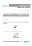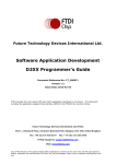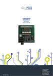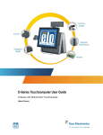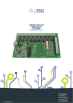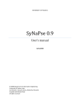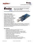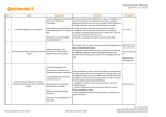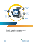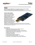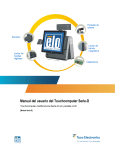
1
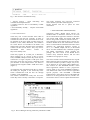
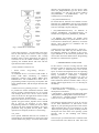
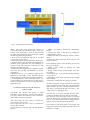
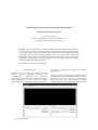
VISUALIZATION APPLICATION FOR SENSOR NETWORKS
Sorin Dumitru, Dorian Cojocaru
University of Craiova,
Faculty of Automation, Computers and Electronics,
Automation & Mechatronics Department
Abstract wireless communications and electronics has been enabled the development of
low-cost sensor networks. The sensor networks can be used for various application areas
(e.g., health, military, home). For different application areas, there are different technical
issues that researchers are currently resolving. In this paper our aim was to design and
implement an application for monitoring the data from a Tmote Sky that is measuring the
temperature. The application was developed to the Czech Technical University in Prague
in the ERASMUS/SOCRATES program.
Keywords: sensor network, visualization.
1. INTODUCTION
Hardware for sensor nodes that combine physical
sensors, actuators, embedded processors, and
communication
components
has
advanced
significantly over the last decade, and made the largescale deployment of such sensors a reality.
Applications range from monitoring applications such
Fig. 1. Main interface
as inventory maintenance over health care to military
applications.
This paper deals with the design and implementation
of an application for monitoring the data from a mote.
The entire project was realized in Visual Studio
DotNet using C# code. The connection between
computer and mote was made using an USB port and
Fig. 2. Tmote Sky module
the downloading of data it was possible using
FD2XX driver.The visualization of data in columns
and in graph is possible using main interface.
applications may be small or large, and the networks
may be wired or wireless. However, ubiquitous
wireless networks of microsensors probably offer the
most potential in changing the world of sensing .
2. SENSOR NETWORKS
Networked microsensors technology is a key
technology for the future. In September 1999,
Business Week heralded it as one of the 21 most
important technologies for the 21st century. Cheap,
smart devices with multiple onboard sensors,
networked through wireless links and the Internet and
deployed in large numbers, provide unprecedented opportunities for instrumenting and controlling homes,
cities, and the environment. In addition, networked
microsensors provide the technology for a broad
spectrum of systems in the defense arena, generating
new capabilities for reconnaissance and surveillance as
well as other tactical applications.
Smart disposable microsensors can be deployed on
the ground, in the air, under water, on bodies, in
vehicles, and inside buildings. A system of
networked sensors can detect and track threats (e.g.,
winged and wheeled vehicles, personnel, chemical and
biological agents) and be used for weapon targeting
and area denial. Each sensor node will have
embedded processing capability, and will potentially
have multiple onboard sensors, operating in the
acoustic, seismic, infrared (IR), and magnetic
modes, as well as imagers and microradars. Also
onboard will be storage, wireless links to neighboring
nodes, and location and positioning knowledge
through the global positioning system (GPS) or local
positioning algorithms.
Networked microsensors belong to the general family
of sensor networks that use multiple distributed
sensors to collect information on entities of interest.
Current and potential applications of sensor networks
include: military sensing, physical security, air traffic
control, traffic surveillance, video surveillance,
industrial and manufacturing automation, distributed
robotics, environment monitoring, and building and
structures monitoring. The sensors in these
2.1 Tmote Sky
Tmote Sky is an ultra low power wireless module for
use in sensor networks, monitoring applications, and
rapid application prototyping. Tmote Sky leverages
industry standards like USB and IEEE 802.15.4 to
interoperate seamlessly with other devices. By using
industry standards, integrating humidity, temperature,
and light sensors, and providing flexible
interconnection with peripherals, Tmote Sky enables
a wide range of mesh network applications.
Tmote Sky is a drop-in replacement for Moteiv’s
successful Telos design. Tmote Sky includes
increased performance, functionality, and expansion.
With TinyOS support out-of-the-box, Tmote Sky
leverages emerging wireless protocols and the open
source software movement. Tmote Sky is part of a
line of modules featuring on-board sensors to
increase robustness while decreasing cost and
package size.
Key Features:
• 250kbps 2.4GHz IEEE 802.15.4 Chipcon Wireless
Transceiver
• Interoperability with other IEEE 802.15.4 devices
• 8MHz Texas Instruments MSP430 microcontroller
(10k RAM, 48k Flash)
• Integrated ADC, DAC, Supply Voltage Supervisor,
and DMA Controller
• Integrated onboard antenna with 50m range indoors
/ 125m range outdoors
• Integrated Humidity, Temperature, and Light
sensors
• Ultra low current consumption
• Fast wakeup from sleep (<6μs)
• Hardware link-layer encryption and authentication
• Programming and data collection via USB
• 16-pin expansion support and optional SMA
antenna connector
Fig. 3. The motelist command line utility
• TinyOS support : mesh networking and
communication implementation
• Complies with FCC Part 15 and Industry Canada
regulations
• Environmentally friendly – complies with RoHS
regulations
This utility optionally lists previously connected
motes that the system has cached (Figure 4).
Invoke motelist with the -h option for more
information.
2.2. PC Communication
Technology FTDI’s “D2XX Direct Drivers” for
Windows offer an alternative solution to our VCP
drivers which allows application software to interface
with FT232 USB UART and FT245 USB FIFO
devices using a DLL instead of a Virtual Com Port.
The architecture of the D2XX drivers consists of a
Windows WDM driver that communicates with the
device via the Windows USB Stack and a DLL which
interfaces the Application Software (written in
VC++, C++ Builder, Delphi, VB etc.) to the WDM
driver. An INF installation file, Uninstaller program
and D2XX Programmers Guide complete the
package. The new version of the D2XX drivers
contains many enhanced features and has been
divided into four groups for clarity.
Tmote Sky uses a USB controller from FTDI to
communicate with the host computer. In order to
communicate with the mote, the FTDI drivers must
be installed on the host. FTDI provides drivers for
Windows, Linux, BSD, Macintosh, and Windows
CE. These drivers are included on the Moteiv CD
shipped with your order. Windows users will need the
Virtual Com Port (VCP) drivers. They may also be
downloaded
from
FTDI’s
website
at:
http://www.ftdichip.com/
Tmote Sky appears as a COM port in Windows’
device manager (or as a device in /dev in Linux,
OSX, and BSD). Multiple Tmote Sky motes may be
connected to a single computer’s USB ports at the
same time. Each mote will receive a different COM
port identifier. In the example below, one Tmote is
connected and assigned COM6 “USB Serial Port”
(Figure 3).
An application may read from Tmote Sky by opening
the COM port assigned to the Tmote Sky mote.
Tmote communicates with the host PC through
USART1 on the TI MSP430.
The motelist command line utility lists all of the
Tmote Sky motes currently connected to a computer.
3. THE TMOTESKY DRIVER(FD2XX)
The Classic Interface Section documents the original
D2XX functions that are retained in this new release.
The Classic Interface provides a simple, easy to use,
set of functions to access these FTDI USB devices.
New sections are “The EEPROM Interface” which
allows application software to read / program the
various fields in the 93C46 EEPROM including a
user defined area which can be used for application
specific purposes; “The FT232BM / FT245BM
Enhancements” which allow control of the additional
features in our 2nd generation devices, and the “FTWin32 API” which is a more sophisticated alternative
Fig. 4. Device Manager showing Tmote Sky installed as COM6
timeouts (FT_SetTimeouts); get the receive queue
status (FT_GetQueueStatus); get the device status
(FT_GetStatus); set and reset the break condition
(FT_SetBreakOn,
FT_SetBreakOff);
and
set
conditions for event notification
• (FT_SetEventNotification).
For FT232 devices, functions are available to set the
baud rate (FT_SetBaudRate), and set a non-standard
baud rate (FT_SetDivisor); set the data characteristics
such as word length, stop bits and parity
• (FT_SetDataCharacteristics); set hardware or
software handshaking (FT_SetFlowControl); set
modem control signals (FT_SetDTR, FT_ClrDTR,
• FT_SetRTS, FT_ClrRTS); get modem status
(FT_GetModemStatus); set special characters such as
event and error characters (FT_SetChars). For FT245
devices, these functions are redundant and can
effectively be ignored.
Fig. 5. D2XX Driver Arhitecture
to the Classic Interface – our equivalent to the native
Win 32 API calls that are used to control a legacy
serial port. Using the FT-Win32 API, existing
Windows legacy Comms applications can easily be
converted to use the D2XX interface simply by
replacing the standard Win32 API calls with the
equivalent FT-Win32 API calls.
“Classic Interface” Functions are:
• D2XX Classic Programming Interface –
Introduction
An FTD2XX device is an FT232 USB UART or
FT245 USB FIFO interfacing to Windows
application software using FTDI’s WDM driver
FTD2XX.SYS. The FTD2XX.SYS driver has a
programming interface exposed by the dynamic link
library FTD2XX.DLL, and this chapter describes that
interface.
• D2XX Classic Programming Interface – Overview
FT_ListDevices returns information about the FTDI
devices currently connected (Figure 4.1). In a system
with multiple devices this can be used to decide
which of the devices the application software wishes
to access (using FT_OpenEx below).
Before the device can be accessed, it must first be
opened. FT_Open and FT_OpenEx return a handle
that is used by all functions in the Classic
Programming Interface to identify the device. When
the device has been opened successfully, I/O can be
performed using FT_Read and FT_Write. When
operations are complete, the device is closed using
• FT_Close.
Once opened, additional functions are available to
reset the device (FT_ResetDevice); purge receive and
transmit buffers (FT_Purge); set receive and transmit
• D2XX Classic Programming Interface – Reference
The functions that make up the D2XX Classic
Programming Interface are defined in this section.
Type definitions of the functional parameters and
return codes used in the D2XX Classic Programming
Interface are contained in the Appendix.
4. PROGRAMMING LANGUAGES
In this section it will be covering what the .NET
Platform is made up of and its layers will be defined.
To start, .NET is a framework that covers all the
layers of software development above the Operating
System. It provides the richest level of integration
among presentation technologies, component
technologies, and data technologies ever seen on
Microsoft, or perhaps any, platform. Secondly, the
entire architecture has been created to make it easy to
develop Internet applications, as it is to develop for
the desktop.
Constituents of .NET Platform are:
• .NET Framework – a completely re - engineered
development environment.
• .NET Products – applications from MS based on the
.NET platform, including Office and Visual Studio.
• .NET Services – facilitates 3rd party developers to
create services on the .NET Platform.
The following diagram (Figure 6) gives an overview
of the .NET architecture. At the bottom of the
diagram is your Operating System above that sits the
.NET framework that acts as an interface to it. The
.NET wraps the operating system, insulating software
developed with .NET from most operating system
specifics such as file handling and memory
allocation.
The next layer up in the framework is called the .NET
Class Framework also referred as .NET base class
Fig. 6. .NET Platform Architecture
library. The .NET Class Framework consists of
several thousand type definitions, where each type
exposes some functionality. All in all, the CLR and
the .NET Class Framework allow developers to build
the following kinds of applications:
• Web Services. Components that can be accessed
over the Internet very easily.
• Web Forms. HTML based applications (Web Sites).
• Windows Forms. Rich Windows GUI applications.
Windows form applications can take advantage of
controls, mouse and keyboard events and can talk
directly to the underlying OS.
• Windows Console Applications. Compilers, utilities
and tools are typically implemented as console
applications.
• Windows Services. It is possible to build service
applications controllable via the Windows Service
Control Manager (SCM) using the .NET Framework.
• Component Library. .NET Framework allows you
to build stand-alone components (types) that may be
easily incorporated into any of the above mentioned
application types.
5. COMPLET REPORT OF THE PROJECT USER’S GUIDE
The folder that contains this project is called
Nettviewer. For being able to view the main interface
you must purchase the following steps: Netviewer>bin->debug->NetviewerInterface.
After those steps, the user is able to visualise the
main interface of the project.
In the upper part the user is able to visualise the
current table with data.
In the right-down corner the user has the following
options:
• adding a new table by pushing the “Add Table”
button;
• changing the name of the table by pushing the
“Change Name” button;
• deleting the table by pushing the “Remove Table”
button;
• entering the name of the table in the text-box with
the label “Name”;
In the left-down corner of the interface, the user has
also a list of options:
• adding a new column by pushing the “Add
Column” button;
• writing a name for the current column in the text
box “Name”;
• choosing the type : byte, boolean, decimal from the
“Type” option;
• changing the name of the column from the “Change
Name” button;
• removing a column from the “Remove Column”.
For data acquisition it must purchase the following
steps: Operations->Take Data The code behind this
interface allows the user to download data from the
mote that is connected in the usb port of our pc. The
“Open” button is opening the mote.
The next step is receiving the data from the mote,
visualising the data and saving them in xml format.
First the user must choose the number of columns
and rows, because the programme will take from the
mote as many data as the result of multiplying the
number of rows with the number of columns.
The acquisition and saving data in xml format will
begin at the time the user pushes the button “Receive
and Save as *.XML”.
Data took from the mote will be displayed in the
lower part of our interface. A new window will
appear after the data are downloaded in which the
user must enter the name of the xml file that will
contain the respective data and the place in the hard
disk where the user wants to store it.
For seeing the saved data in table form, we must
return to the main interface, and from the File menu
choose Open and than double-click on the name of
the file. The data from the respective xml file will be
arranged into columns for a better visualisation. The
number of the rows and columns will be exactly the
one choosed from the Data Acquisition interface.
Having the data in this format, now the graph
visualisation can be done.
From the View menu, we choose View Graph. The
result of this command is the graph visualisation of
the data that are in the respective table. Our project
also gives to the user the possibility of saving the data
in CSV format and export them to other programmes
like Excel or Matlab :
For this the user must choose from File menu the
option Export As *.CSV. It has also been made
possible for the user to write some comments about a
data acquisition and save the comments with
respective xml, so that in future when the user wants
to reanalyze the xml file, he/she can already have
some information about the respective data. This
function it is situated in the File menu, Save
Description.
6. CONCLUSIONS
As it has showed in the previous chapters, this
application is implemented in Visual Studio 2005, in
the C#/C++ language and it’s purpose is the data
acquisition from a sensor network, saving those data
into an XML format, and visualize them into a
tabular format and into a graphical format .
The device that was used, Tmote Sky, has a large
area of applicability. It has specialized drivers that are
used for the control and the communication between
the data destination computer and the acquisition
mote, the transfer, in our case, being made by USB
port.
The user has the possibility to export the downloaded
data in other programs like Matlab or Excel. It is also
possible the introducing of some comments about the
downloaded data.
With the help of the Netviewer interface it is possible
to administrate the downloaded data, to modify those
data, to delete or to introduce new columns and new
data and save them into an XML and CSV format.
The application includes also a very complete
comment of the code and a user’s manual, so that any
future developer of this application to modify it by
adding other acquisition facilities or saving/exporting
of the data. For example there can be realised other
options of extanding, so that the data not to be
downloaded only from one mote, but from a larger
number of motes by forming a database of the used
motes and appealing this database every time the user
wants to download data. It is also possible to form a
database with motes that are measuring different type
of data such as: temperature, humidity, pressure etc.
REFERENCES
Edgar H. Callaway (2004), “Wireless Sensor
Networks: Architectures and Protocols”
O’Reilly (2003), „.NET and XML”
Scott Short (2002), “Building XML Web Services for
the Microsoft .NET Platform”
Yee Chong and Srikanta P. Kumar (2002), “Sensor
Networks:
Evolution, Opportunities
and
Challenges”
http://www.ftdichip.com/Documents/ProgramGuides
http://download.microsoft.com/download
http://www.btnode.ethz.ch/pub/uploads/Projects
http://www.codeproject.com/csharp/zedgraph.asp
http://nesl.ee.ucla.edu/tutorials/mobicom02
http://diy-zoning.sourceforge.net/Advanced