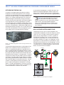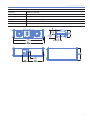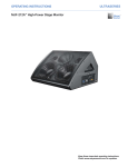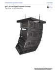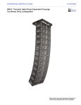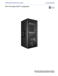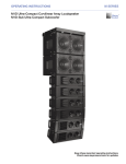
1
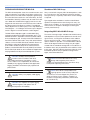
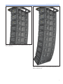
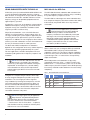
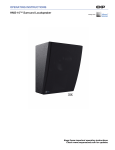
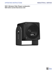
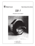
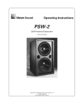
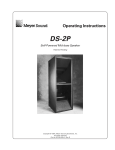
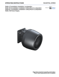
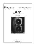
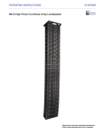
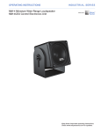
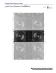
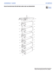
OPERATING INSTRUCTIONS ADDENDUM
M SERIES
MILO 60 High-Power Narrow Coverage
Curvilinear Array Loudspeaker
Addendum to MILO Operating Instructions (PN 05.132.095.01 A)
Keep these important operating instructions.
Check www.meyersound.com for updates.
DECLARATION OF CONFORMITY ACCORDING TO ISO/IEC GUIDE 22 AND EN 45014
Manufacturer's Name:
Meyer Sound Laboratories Inc.
Manufacturer's Address:
2832 San Pablo Avenue
Berkeley, CA 94702-2204, USA
declares that the products
Product Name: MILO 60
conforms to the following Product Specifications
Safety: EN60065: 1998
IEC60065: 1998
EMC:
EN55103-1: 1997 emission1
EN55103-2: 1997 immunity2
This device also complies with EN 55103-1 & -2.
Operation is subject to the following two conditions:
(1) this device may not cause harmful interference, and
(2) this device must accept any interference received, including
interference that may cause undesired operation.
Supplementary Information
The product herewith complies with the requirements of the Low
Voltage Directive 73/23/EEC and the EMC Directive 89/336/EEC.
Office of Quality Manager
Berkeley, California USA
January 30, 2005
European Contact: Your local Meyer Sound dealer or Meyer Sound
Germany, GmbH. Carl Zeiss Strasse 13, 56751 Polch, Germany.
Telephone: 49.2654.9600.58 Fax: 49.2654.9600.59
Environmental specifications for Meyer Sound Electronics products
Operating temperature
Non-operating temperature
Humidity
Operating altitude
Non-operating altitude
Shock
Vibration
0°C to +45°C
-40°C to +75°C
to 95% at 35°C
to 4600 m (15,000ft)
to 6300 m (25,000ft)
30 g 11 msec half-sine on each of
6 sides
10 Hz to 55 Hz (0.010 peak-to-peak
excursion)
Made by Meyer Sound Laboratories
Berkeley, California USA
European Office:
Meyer Sound Lab. GmbH
Carl Zeiss Strasse 13
56751 Polch, Germany
© 2005 Meyer Sound. All rights reserved.
Operating Instructions Addendum: MILO 60 High-Power Narrow Coverage Curvilinear Array Loudspeaker
The contents of this manual are furnished for informational purposes only, are subject to change without notice, and should not be construed as a
commitment by Meyer Sound Laboratories Inc. Meyer Sound assumes no responsibility or liability for any errors or inaccuracies that may appear
in this manual. Except as permitted by applicable copyright law, no part of this publication may be reproduced, stored in a retrieval system, or
transmitted, in any form or by any means, electronic, mechanical, recording or otherwise, without prior written permission from Meyer Sound.
MILO, TruPower, RMS and REM are trademarks of Meyer Sound. Meyer Sound, Meyer Sound MAPP Online, SIM and QuickFly are registered
trademarks of Meyer Sound Laboratories Inc. (Reg. U.S. Pat. & Tm. Off.). All third-party trademarks mentioned herein are the property of their
respective trademark holders.
Printed in the U.S.A.
Part Number: 05.132.095.02 A
ii
SYMBOLS USED
These symbols indicate important safety or operating features in this booklet and on the chassis:
!
Dangerous voltages: risk of
electric shock
Important operating
instructions
Frame or chassis
Protective earth ground
Pour indiquer les risques
résultant de tensions
dangereuses
Pour indequer important
instructions
Masse, châssis
Terre de protection
Zu die gefahren von
gefährliche spanning zeigen
Zu wichtige betriebsanweisung und unterhaltsanweisung zeigen
Rahmen oder chassis
Die schutzerde
Para indicar voltajes
peligrosos.
Instrucciones importantes
de funcionamiento y/o
manteniento
Armadura o chassis
Tierra proteccionista
IMPORTANT SAFETY INSTRUCTIONS
1
Read these instructions.
2. Keep these instructions.
3. Heed all warnings.
4. Follow all instructions.
11. Only use attachments/accessories specified by Meyer
Sound.
12. Use only with the caster rails or rigging specified by
Meyer Sound, or sold with the loudspeaker. Handles
are for carrying only.
5. Do not use this loudspeaker near water.
6. Clean only with dry cloth.
7. Do not block any ventilation openings. Install in accordance with Meyer Sound’s installation instructions.
8. Do not install near any heat sources such as radiators,
heat registers, stoves, or other apparatus that produce
heat.
9. Do not defeat the safety purpose of the groundingtype plug. A grounding-type plug has two blades and
a third grounding prong. The third prong is provided
for your safety. If the provided plug does not fit into
your outlet, consult an electrician for replacement of
the obsolete outlet.
10. Protect the power cord from being walked on or
pinched, particularly at plugs, convenience receptacles, and the point where they exit from the loudspeaker. The AC mains plug or appliance coupler shall
remain readily accessible for operation.
CAUTION: Rigging should only be done by
experienced professionals.
13. Unplug this loudspeaker during lightning storms or
when unused for long periods of time.
14. Refer all servicing to qualified service personnel.
Servicing is required when the loudspeaker has been
damaged in any way, such as when the power-supply cord or plug has been damaged; liquid has been
spilled or objects have fallen into the loudspeaker; rain
or moisture has entered the loudspeaker; the loudspeaker has been dropped; or when for undetermined
reasons the loudspeaker does not operate normally.
iii
SAFETY SUMMARY
English
-
-
-
-
-
-
To reduce the risk of electric
shock, disconnect the loudspeaker
from the AC mains before installing
audio cable. Reconnect the power
cord only after making all signal
connections.
Connect the loudspeaker to a
two-pole, three-wire grounding
mains receptacle. The receptacle
must be connected to a fuse or
circuit breaker. Connection to any
other type of receptacle poses a
shock hazard and may violate local
electrical codes.
Do not install the loudspeaker
in wet or humid locations
without using weather protection
equipment from Meyer Sound.
Do not allow water or any
foreign object to get inside the
loudspeaker. Do not put objects
containing liquid on or near the
unit.
To reduce the risk of overheating
the loudspeaker, avoid exposing it
to direct sunlight. Do not install the
unit near heat-emitting appliances,
such as a room heater or stove.
This loudspeaker contains
potentially hazardous voltages. Do
not attempt to disassemble the
unit. The unit contains no userserviceable parts. Repairs should
be performed only by factorytrained service personnel.
-
-
-
Deutsch
-
-
Français
-
-
-
iv
Pour réduire le risque
d’électrocution, débrancher
la prise principale de l’hautparleur, avant d’installer le câble
d’interface allant à l’audio. Ne
rebrancher le bloc d’alimentation
qu’après avoir effectué toutes les
connections.
Branchez l’haut-parleur dans une
prise de courant à 3 dérivations
(deux pôles et la terre). Cette
prise doit être munie d’une
protection adéquate (fusible ou
coupe-circuit). Le branchement
dans tout autre genre de prise
pourrait entraîner un risque
d’électrocution et peut constituer
une infraction à la réglementation
locale concernant les installations
électriques.
Ne pas installer l’haut-parleur dans
un endroit où il y a de l’eau ou une
humidité excessive.
Ne pas laisser de l’eau ou tout
objet pénétrer dans l’haut-parleur.
Ne pas placer de r´cipients
contenant un liquide sur cet
appareil, ni à proximité de celui-ci.
Pour éviter une surchauffe de
l’haut-parleur, conserver-la à
l’abri du soleil. Ne pas installer à
proximité d’appareils dégageant
de la chaleur tels que radiateurs
ou appareils de chauffage.
Ce haut-parleur contient des
circuits haute tension présentant
un danger. Ne jamais essayer
de le démonter. Il n’y a aucun
composant qui puisse être
réparé par l’utilisateur. Toutes les
réparations doivent être effectuées
par du personnel qualifié et agréé
par le constructeur.
-
-
-
Um die Gefahr eines elektrischen
Schlages auf ein Minimum zu
reduzieren, den Lautsprecher
vom Stromnetz trennen, bevor
ggf. ein Audio-Schnittstellensign
alkabel angeschlossen wird. Das
Netzkabel erst nach Herstellung
aller Signalverbindungen wieder
einstecken.
Der Lautsprecher an eine
geerdete zweipolige DreiphasenNetzsteckdose anschließen.
Die Steckdose muß mit einem
geeigneten Abzweigschutz
(Sicherung oder Leistungsschalter)
verbunden sein. Der Anschluß
der unterbrechungsfreien
Stromversorgung an einen
anderen Steckdosentyp kann
zu Stromschlägen führen und
gegen die örtlichen Vorschriften
verstoßen.
Der Lautsprecher nicht an einem
Ort aufstellen, an dem sie mit
Wasser oder übermäßig hoher
Luftfeuchtigkeit in Berührung
kommen könnte.
Darauf achten, daß weder
Wasser noch Fremdkörper in
das Innere den Lautsprecher
eindringen. Keine Objekte, die
Flüssigkeit enthalten, auf oder
neben die unterbrechungsfreie
Stromversorgung stellen.
Um ein Überhitzen dem
Lautsprecher zu verhindern,
das Gerät vor direkter
Sonneneinstrahlung fernhalten
und nicht in der Nähe von
wärmeabstrahlenden
-
Haushaltsgeräten (z.B. Heizgerät
oder Herd) aufstellen.
Im Inneren diesem Lautsprecher
herr-schen potentiell gefährliche
Spannungen. Nicht versuchen,
das Gerät zu öffnen. Es
enthält keine vom Benutzer
reparierbaren Teile. Reparaturen
dürfen nur von ausgebildetem
Kundenienstpersonal durchgeführt
werden.
Español
-
-
-
-
-
Para reducir el riesgo de descarga
eléctrica, desconecte de la red
de voltaje el altoparlante antes de
instalar el cable de señal de audio.
Vuelva a conectar la alimentacion
de voltaje una vez efectuadas
todas las interconexiones de
señalizacion de audio.
Conecte el altoparlante a un
tomacorriente bipolar y trifilar
con neutro de puesta a tierra.
El tomacorriente debe estar
conectado a la protección de
derivación apropiada (ya sea
un fusible o un disyuntor). La
conexión a cualquier otro tipo de
tomacorriente puede constituir
peligro de descarga eléctrica
y violar los códigos eléctricos
locales.
No instale el altoparlante en
lugares donde haya agua o
humedad excesiva.
No deje que en el altoparlante
entre agua ni ningún objeto
extraño. No ponga objetos con
líquidos encima de la unidad ni
cerca de ella.
Para reducir el riesgo de
sobrecalentamiento, no exponga
la unidad a los rayos directos del
sol ni la instale cerca de artefactos
que emiten calor, como estufas o
cocinas.
Este altoparlante contiene
niveles de voltaje peligrosos en
potencia. No intente desarmar la
unidad, pues no contiene piezas
que puedan ser repardas por el
usuario. Las reparaciones deben
efectuarse únicamente por parte
del personal de mantenimiento
capacitado en la fábrica.
Operating Instructions Addendum: MILO 60
MILO™ 60 HIGH-POWER NARROW COVERAGE CURVILINEAR ARRAY
INTRODUCING THE MILO 60
A variation on the popular MILO high-power curvilinear
loudspeaker, the MILO 60 high-power narrow coverage
curvilinear array loudspeaker excels where controlled narrow
horizontal coverage is needed. The self-powered MILO 60
(Figure 1) is a compact, lightweight four-way system that
provides 60 degrees of horizontal coverage, and vertical
coverage matching the original MILO (nominally 10 degrees
in the high-frequency and very-high-frequency sections;
vertical coverage across all frequency bands within a line array varies, depending on the length and configuration of the
array). The coverage pattern is optimized for applications requiring tight horizontal coverage, such as at the top in mixed
arrays with standard MILO line array loudspeaker systems,
or for sidefill systems to extend horizontal coverage.
Figure 1. The MILO 60 high-power narrow coverage curvilinear array
loudspeaker
The MILO 60 loudspeaker produces a peak output of 140
dB SPL with exceptionally flat phase and frequency response. Its wide operating frequency range (60 Hz to 18
kHz) is complemented by extended high-frequency headroom and a dedicated very-high-frequency section (4.2 kHz
to 18 kHz) that renders delicate transient information with
detailed resolution through its coverage pattern. The driver
complement is identical to that of MILO, with the compression drivers in the high- and very-high-frequency sections
going through patented REM™ ribbon emulation manifolds
into custom 60-degree constant-directivity horns. Control
electronics are designed to maintain flat frequency and
phase response throughout the loudspeaker’s coverage
pattern. The MILO 60 loudspeaker’s acoustical characteristics are designed to facilitate seamless integration when
used with other MILO curvilinear array elements.
As with all MILO loudspeakers, the MILO 60 comes standard with integrated amplification, RMS™ remote monitoring system, TruPower® limiting system, and AlignaLink
hardware for use with the MILO QuickFly® rigging hardware.
NOTE: For more detail about these features,
plus information on the SIM® source independent measurement system and the Meyer Sound
MAPP Online® acoustical prediction program,
please see the MILO High-Power Curvilinear Array
Loudspeaker Operating Instructions (Part Number
05.132.095.01).
MILO 60 DRIVER INTERCONNECTIONS
The MILO 60 uses the same 4-channel amplifier as the
standard MILO loudspeaker, and the low-frequency control
card is the same. The upper control card for the high-frequency and very-high-frequency sections is specific to
the MILO 60. Each front 4-ohm, 12-inch, low-frequency
cone driver is powered by one 1125-watt channel of the
HP-4/MILO amplifier. The single 4-inch diaphragm, 8-ohm
high-frequency compression driver is powered by a single
560-watt channel and the three 2-inch diaphragm, 12-ohm
very-high-frequency compression drivers share the fourth
1125-watt channel. The following diagram shows how the
drivers are connected to the amplifier.
Very High
Mid-High
60
Figure 2. MILO 60 internal wiring harness diagram
1
Operating Instructions Addendum: MILO 60
FLYING AND ARRAYING THE MILO 60
Standalone MILO 60 Arrays
The MILO 60 loudspeaker shares the same dimensions and
rigging components as the MILO to facilitate seamless integration, and uses the MG-3D/M multipurpose grid for flying.
Since the MILO 60 is identical in size to the MILO, all of the
standard MILO QuickFly hardware may be used. Each cabinet is fitted with the MRF-MILO rigging frame for use with
AlignaLinks that attach to the front and rear of the cabinets
for splaying them when flown or stacked. The hardware
allows adjustments of cabinet splay in nine steps between 0
and 5 degrees — in 0.5-degree increments up to 3 degrees,
and in 1-degree increments between 3 and 5 degrees.
Arrays can be built using only MILO 60 loudspeakers, creating a sound source with a 60-degree horizontal coverage.
This type of array is especially useful when narrow coverage
is required.
The MG-3D/M multipurpose grid is used for both flying
and ground support for the MILO loudspeaker arrays. The
MLK-MILO link kit is required to connect any MILO cabinet
to the multipurpose grid. A variety of transition hardware allows MILO cabinets to be used in arrays with other M Series
cabinets such as the M3D, M3D-Sub, and M2D. Please see
the M Series section of the QuickFly Overview brochure
(Part Number 18.990.126.02 D) for an overview of these
products, and the MG-3D/M Assembly Guide (Part Number
05.132.036.01) for details on the installation and applications
of flying hardware for Meyer Sound loudspeaker systems.
CAUTION: All Meyer Sound products
must be used in accordance with local,
state, federal and industry regulations. It is the
owner’s and/or user’s responsibility to evaluate the
reliability of any rigging method for their application.
Rigging should be carried out only by experienced
professionals.
CAUTION: Always use properly rated rigging
hardware.
CAUTION: It is important to inspect rigging
hardware regularly and replace worn or
damaged components immediately.
2
Typical applications would be as audience side-fill loudspeakers to complement the front-facing main arrays in a
wider venue or stadium, as main reinforcement array(s) for
narrow venues, or for precise 60-degree sectioning of a
centrally mounted array.
Integrating MILO 60 with MILO Arrays
The various coverage angles available with the MILO family
of loudspeakers may be used to optimize the overall coverage of venues, assuring that all members of the audience
receive consistent sound — with as uniform frequency response and SPL as possible. The standard MILO cabinets
with their 90-degree horizontal coverage may be supplemented with the extended coverage MILO 120 cabinets at
the bottom of the array to provide fill to the audience nearer
to the stage. MILO 60 cabinets would most often be used
toward the top of the array to provide coverage for the
higher, more distant balconies.
NOTE: For more information on line array
design and integration please refer to
Chapter 4 of the MILO High-Power Curvilinear Array
Loudspeaker Operating Instructions.
NOTE: Since MILO 120 expanded coverage high-power curvilinear array loudspeakers make use of custom AlignaLinks, please see
details on how to use this rigging in Chapter 7 of
the MILO 120 Operating Instructions (Part Number:
05.142.003.01 A).
Operating Instructions Addendum: MILO 60
Figure 3. Example configuration: combined MILO 60 (top three cabinets) and MILO array
Figure 4. Example configuration: combined MILO 60 (top), MILO, and
MILO 120 (bottom) array
3
Operating Instructions Addendum: MILO 60
USING SUBWOOFERS WITH THE MILO 60
MILO 60 with the M3D-Sub
A MILO 60 system (or combined MILO 60/MILO/MILO 120
system) will provide full bandwidth frequency response
down to 60 Hz. The height of the array (number of cabinets)
will determine the total SPL available and how much low
frequency energy can be provided, proportional to the
upper-frequency spectrum.
The M3D-Sub directional subwoofer adds substantial lowfrequency headroom to MILO curvilinear arrays, extending
the system frequency response to 30 Hz.
If higher SPL is necessary, or the program content requires
additional low-frequency energy (e.g., the reinforcement
of popular music), then subwoofers should be used to
augment your MILO curvilinear array.
The M3D-Sub has advantages over other subwoofers due
to its unique low-frequency directional control and its ability
to be vertically arrayed with MILO since they share the
same width.
NOTE: For most applications, you want to
keep low frequencies from being produced
behind the array to reduce or eliminate the low
frequency reverberant noise traditionally associated
with large-scale, full-range loudspeaker arrays. The
M3D-Sub’s award-winning and patent-pending
cardioid directional pattern provides maximum lowfrequency attenuation from 6 to 12 meters behind
the cabinet (-20 dB at 8 meters).
Meyer Sound subwoofers, such as the M3D-Sub and
700-HP, can achieve frequency response down in the 30
Hz range, extending the system response appreciably and
increasing the acoustic power of the system in the lowest
frequencies. In addition, the use of high-pass filters to drive
a MILO system with subwoofers increases the headroom of
the array in the lowest end of its usable spectrum.
The ideal ratio of MILO loudspeakers to subwoofers
depends on the configuration of the array and the frequency
content of the signal being reproduced by the system.
For most applications, two MILO loudspeakers for each
subwoofer yields good results in frequency response and
headroom.
NOTE: The limit LEDs indicate when the safe
power level is exceeded. If the subwoofers
used in the system begin to limit before reaching the
required SPL at low frequencies, consider adding
more subwoofers to satisfy the SPL requirements
without exposing the drivers to excessive heat and/
or excursion.
Table 1 shows how you can integrate MILO (or combined
MILO 60/MILO/MILO 120) arrays with the M3D-Sub
subwoofer using the LD-3 line driver’s filtering capabilities
to fine-tune the system. All the data in Table 1 is based on
system designs with a 2:1 ratio and in a close-proximity,
coplanar orientation.
When loudspeakers and subwoofers are physically
separated by more than 4 feet — or delay must be used
between them — a measurement system such as the SIM
audio analyzer (covered in Chapter 5 of the MILO Operating
Instructions) should be used to determine the correct delay
and polarity.
Table 1. MILO 60/MILO/MILO 120 and M3D-Sub
Using the LD-3 compensating line driver’s filters helps
to easily integrate and optimize your MILO arrays with
subwoofers. The use of high-pass filters augments
array headroom by removing lower frequencies near the
unit’s lower operating range, while low-pass filters can
remove unwanted mid-low frequencies reproduced by
the subwoofers. The use of these filters reduces the area
of overlap and minimizes the interaction and possible
cancellations between subsystems.
NOTE: Full-range signals may be applied to
Meyer Sound’s self-powered loudspeakers
and subwoofers because they have built-in active
crossovers. However, the use of external filters
— like the ones in the LD-3 line driver — is optional,
and should be used very carefully to minimize phase
shifts that can cause cancellations.
4
HPF
LPF
ø Reverse
Result
Switch
80
80
Engaged
Flat response
80
Off
Engaged
Flat response
160
Off
Engaged
Very flat response
Off
Off
Off
Boost in the 80 Hz region
Operating Instructions Addendum: MILO 60
MILO 60 with the 700-HP Subwoofer
In applications where M3D-Sub features like directional
low-frequency control are not needed, a MILO 60 array
can be deployed in combination with Meyer Sound 700HP subwoofers. The 700-HP subwoofer extends the MILO
system frequency response down to 30 Hz.
Table 2 shows how you can integrate MILO (or combined
MILO 60/MILO/MILO 120) arrays with 700-HP using the
LD-3 line driver’s filtering capabilities to fine-tune the
system. All data in Table 2 is based on system designs with
a 2:1 ratio and in a close-proximity, coplanar orientation.
When loudspeakers and subwoofers are physically
separated by more than 4 feet – or delay must be used
between them – a measurement system such as SIM
should be used to determine the correct delay and polarity.
Table 2. MILO 60/MILO/MILO 120 and 700-HP Subwoofer
HPF
LPF
ø Reverse
Additional information on the LD-3 can be found in the
LD-3 Compensating Line Driver Operating Instructions (Part
Number 05.118.040.01 B).
Figure 5. LD-3 compensating line driver, front panel
USING THE RMS REMOTE MONITORING
SYSTEM WITH THE MILO 60
Meyer Sound’s RMS remote monitoring system is fitted as
standard, providing comprehensive monitoring of system
performance parameters over a Windows®-based network.
For details, please see Chapter 3 of the MILO Operating
Instructions.
Result
Switch
Off
Off
Engaged
Boost in the 100 Hz region
160
Off
Engaged
Very flat response
80
80
Off
Very flat response
160
80
Off
Flat response
LD-3 LINE DRIVER SETTINGS FOR THE MILO 60
LD-3 Array Correction
The LD-3 line driver’s array correction filters are used to
compensate for the low and low-mid frequency buildup that
occurs in all line arrays. Because the low and mid-low sections of all MILO systems are identical, set the Array Type
to MILO and set the Array Size to match the total number
of loudspeakers in the array; this is true of reinforcement
systems consisting of the MILO 60 by itself or in combination with other MILO loudspeakers.
Figure 6. MILO 60 loudspeaker icon in RMS page
USING MAPP ONLINE™ FOR SYSTEM DESIGNS
INCLUDING THE MILO 60
The MAPP Online acoustical prediction program is a powerful, cross-platform, Java-based application for accurately
predicting the coverage pattern, frequency response,
impulse response and maximum SPL output of single or
arrayed Meyer Sound loudspeakers. Coverage data for the
MILO 60 cabinet is included in the MAPP Online database.
Detailed information on the use and application of MAPP
Online can be found in the MILO Operating Instructions at
the end of the “Line Arrays and System Integration" section.
MAPP Online can be accessed through the Meyer Sound
Web site at: www.meyersound.com.
LD-3 Atmospheric Correction
Use the Atmospheric Correction section of the LD-3
to compensate for the air attenuation effects on higher
frequencies, which are especially noticeable in longer-throw
applications (typical of a stadium, an outdoor shed, and
other larger events). Enter the altitude plus the temperature
and humidity conditions at the venue, and then set the
distance from the array to the listeners to introduce the
correction. With the use of the individual distance settings
available on each of the outputs of the LD-3, the line array
can be divided into up to three sections to correspond to the
loudspeaker-to-audience distance for the near, medium and
long-throw sections of the array.
WEATHER PROTECTION OPTIONS
A weather-protected version with a folding rain hood that
safeguards the electronics is optionally available. See Appendix A within the MILO Operating Instructions for details
on how to deploy the rain hood.
5
Operating Instructions Addendum: MILO 60
6
Operating Instructions Addendum: MILO 60
APPENDIX A: MILO 60 SPECIFICATIONS
ACOUSTICAL
Note: The low-frequency power response of the system will increase according to the length of the array.
Operating frequency range
60 Hz - 18 kHz
Note: Recommended maximum operating frequency range. Response depends upon
loading conditions and room acoustics.
Free field frequency
response
65 Hz - 17.5 kHz ±4 dB
Phase response
750 Hz - 16 kHz ±30°
Maximum peak SPL
140 dB
Note: Measured with 1/3-octave frequency resolution at 4 meters.
Note: Measured with music at 1 meter.
Dynamic range
>110 dB
Horizontal coverage
60°
Vertical coverage
Varies, depending on array length and configuration
Acoustical crossover
560 Hz, 4.2 kHz
Note: At these frequencies, the transducers produce equal sound pressure levels: 560 Hz
for the low-mid and mid-high and 4.2 kHz for the mid-high and very-high frequency drivers.
TRANSDUCERS
Low/low-mid frequency
Two 12" cone drivers with neodymium magnets
Nominal impedance: 4 Ω
Voice coil size: 4"
Power-handling capability: 1200 W (AES)
Note: Power handling is measured under AES standard conditions: transducer driven
continuously for two hours with band limited noise signal having a 6 dB peak-average ratio.
Note: To eliminate interference at short wavelengths, the two 12-inch drivers work in combination at low frequencies
(60 Hz – 300 Hz). At mid frequencies (300 Hz – 560 Hz) only one cone driver is fed from the crossover to maintain optimal
polar and frequency response characteristics.
Mid-high frequency
One 4" compression driver
Nominal impedance: 8 Ω
Voice coil size: 4"
Diaphragm size: 4"
Exit size: 1.5"
Power handling capability: 250 W (AES) on REM
Note: Power handling is measured under AES standard conditions: transducer driven
continuously for two hours with band limited noise signal having a 6 dB peak-average ratio.
Note: The driver is coupled to a 60-degree-horizontal constant-directivity horn through a proprietary acoustical
combining manifold (REM).
Very-high frequency
Three 2" compression drivers
Nominal impedance: 12 Ω
Voice coil size: 2"
Diaphragm size: 2"
Exit size: 0.75"
Power handling capability: 100 W (AES) on REM
Note: Power handling is measured under AES standard conditions: transducer driven
continuously for two hours with band limited noise signal having a 6 dB peak-average ratio.
Note: The three drivers are coupled to a 60-degree-horizontal constant-directivity horn through a proprietary acoustical
combining manifold (REM).
7
Operating Instructions Addendum: MILO 60
AUDIO INPUT
Type
Differential, electronically balanced
Max. common mode range
±15 V DC, clamped to earth for voltage transient protection
Connectors
Female XLR input with male XLR loop output or VEAM
Input impedance
10 kΩ differential between pins 2 and 3
Wiring
Pin 1: Chassis/earth through 220 kΩ, 1000 pF, 15 V clamp network to provide virtual
ground lift at audio frequencies
Pin 2: Signal +
Pin 3: Signal Case: Earth ground and chassis
DC Blocking
None on input, DC blocked through signal processing
CMRR
>50 dB, typically 80 dB (50 Hz – 500 Hz)
RF filter
Common mode: 425 kHz
Differential mode: 142 kHz
TIM filter
<80 kHz, integral to signal processing
Nominal input sensitivity
0 dB V (1 V rms, 1.4 V pk) continuous is typically the onset of TPL limiting for noise and
music.
Input level
Audio source must be capable of producing a minimum of +20 dBV (10 V rms, 14 V pk)
into 600 Ω in order to produce maximum peak SPL over the operating bandwidth of the
loudspeaker
AMPLIFIERS
Amplifier type
Output power
Complementary power MOSFET output stages (class AB/H)
3935 W (four channels; 3 x 1125 W, 1 x 560 W)
Note: Amplifier wattage rating is based on the maximum unclipped burst sine-wave rms
voltage the amplifier will produce in to the nominal load impedance low, mid and very high
channels 67 V rms (95 V pk) into 4 ohms; mid-high channel 67 V rms (95 V pk) into 8 ohms.
THD, IM TIM
< .02%
Load capacity
4 Ω low, low-mid and very-high channels; 8 Ω mid-high channel
Cooling
Forced air cooling, 4 fans total (2 ultra-high-speed reserve fans)
AC POWER
AC power connector
250 V AC NEMA L6-20 (twistlock) inlet, IEC 309 male inlet, or
VEAM all-in-one connector (integrates AC, audio and network)
Voltage selection
Automatic, two ranges, each with high-low voltage tap (uninterrupted)
Safety agency rated
operating voltage
95 V AC – 125 V AC, 208 V AC - 235 V AC, 50/60 Hz
Turn on/turn off points
85 V AC – 134 V AC; 165 V AC - 264 V AC
Current Draw
Idle current
1.1 A rms (115 V AC), 0.55 A rms (230 V AC), 1.3 A rms (100 V AC)
Max. long-term continuous
current (>10 sec)
11.2 A rms (115 V AC), 5.6 A rms (230 V AC), 12.9 A rms (100 V AC)
Burst Current (<1 sec)
14.4 A rms (115 V AC), 7.2 A rms (230 V AC), 16.6 A rms (100 V AC)
Note: AC power cabling must be of sufficient gauge so that under burst current rms conditions, cable transmission
losses do not drop voltage below specified operating range at the speaker.
Ultimate Short-Term Peak
Current Draw
32 A rms (115 V AC), 16 A rms (230 V AC), 37 A rms (100 V AC)
Inrush Current
7 A rms (115 and 110 V AC), 10 A rms (230 V AC)
RMS NETWORK
Equipped for two conductor twisted-pair network, reporting all operating parameters of
amplifiers to system operator’s host computer.
8
Operating Instructions Addendum: MILO 60
PHYSICAL: MILO 120 Loudspeaker
Enclosure
Multi-ply hardwood
Finish
Black textured
Protective grille
Powder-coated hex stamped steel
Rigging
QuickFly MRF-MILO rigging frame, custom AlignaLink connectors and quick release pins
Dimensions
54.00" w x 14.47" h x 22.00" d (1372 mm x 368 mm x 559 mm)
Weight
235 lbs (106.60 kg)
�
�
�
�
�
�
�
�
�
�
9
Operating Instructions Addendum: MILO 60
10
Meyer Sound Laboratories Inc.
2832 San Pablo Avenue
Berkeley, CA 94702
www.meyersound.com
T: +1 510 486.1166
F: +1 510 486.8356
© 2005
Meyer Sound Laboratories Inc.
05.132.095.02 A