1
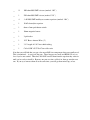
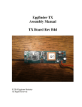
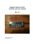
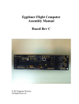
Eggtimer TRS Flight Computer
Assembly Manual
Board Rev A5
© 2014 Eggtimer Rocketry
All Rights Reserved
California Proposition 65 Warning
WARNING: This product contains chemicals (lead) known to the State of
California to cause cancer and birth defects or reproductive harm.
This kit includes a special low-temperature ultra-fine leaded solder wire.
Including the solder with the kit ensures that you will have solder that can be
used to mount the surface-mount parts in the kit. Leaded solders have been used
for over a century in electronic assembly, but you should take the following
precautions when using it (or just about any chemical, for that matter):
• Do not eat or drink while using it
• Wash your hands after handling it
• Keep it in the protective bag when you’re not using it
The MSDS can be found at
http://www.kester.com/download/245%20FluxCored%20Wire%20Lead%20Allo
y%20SDS.pdf
The European Union RoHS (Restriction on Hazardous Substances) regulations
exempt kits such as the Eggtimer TRS from its regulations, because they are not
for resale and since it is well known that hand soldering with non-leaded solder is
much more difficult and more damaging to heat-sensitive components.
Important Regulatory Information
This device complies with Part 15 of the FCC Rules. Operation
is subject to the following two conditions: (1) this device may
not cause harmful interference, and (2) this device must
accept any interference received, including interference that
may cause undesired operation.
It is intended to be used ONLY for educational and
experimental use in Model Rockets and Class II/III amateur
High Power Rockets which are classified as aircraft by the
Federal Aircraft Administration (CFR 14 §101.25), and which
must by FAA and NFPA regulations be operated at least 1,500’
away from any populated buildings. Although unlikely, this
device may cause interference with consumer devices that
run on the unlicensed 902-928 MHz band, and therefore must
not be used in residential areas.
The Eggtimer TRS uses RF modules in the 902-928 MHz ISM band manufactured by Hope
RF, model HM-TRP-915. They are intended to be used in the United States or other countries
with similar RF band and regulatory rules. These modules have been tested by Hope RF to be
compliant with the FCC Part 15 regulations for non-licensed intentional emitters, and as such
have been permitted to be imported into the US. However, Hope RF (at the time of this
document) has not obtained formal certification with the FCC. As a hobby kit, designed for
educational and experimental purposes, the Eggtimer TRS is considered by the FCC to be
“generally exempt” from authorization requirements. Nonethless, we have made a good faith
attempt to comply with all technical regulations, and you should too by building it exactly as
per the instructions, and by using only the antenna on the transmitter module that we
recommend in the instructions, or a suitable replacement as outlined in the Appendix.
Because the Eggtimer TRS runs on an unlicensed band, there is no protection against
interference from other sources; basically, you get what you get. We’ve done substantial
testing and are confident that your Eggtimer TRS system is unlikely to be significantly affected
by outside radio sources, but there’s no guarantee.
If your Eggtimer TRS causes interference in a residential setting, or with licensed radio
systems (such as TV or ham radio), you must stop using it until you correct the problem. This
is extremely unlikely given the small amount of power and the “tightness” of the transmitter’s
output, and in particular the distance from any population that HPR rockets must be flown.
Nevertheless, you need to be aware of this, and be willing to abide by the rules. These are the
same rules that govern other non-licensed transmitters, such as cordless phones, WiFi and
Bluetooth® devices, and garage door openers.
Important Links:
FCC Part 15 (governing unlicensed intentional emitters)
http://www.ecfr.gov/cgi-bin/textidx?SID=adb12f74b498e43ec453f7899d9df0fd&node=47:1.0.1.1.16&rgn=div5
Hope RF HM-TRP Documentation (FCC test documentation)
http://www.hoperf.com/upload/rf/HM-TRP-915(20dBm)-FCC.pdf
FAA Regulations for Amateur Rocketry (Part 101)
http://www.ecfr.gov/cgi-bin/textidx?c=ecfr&rgn=div5&view=text&node=14:2.0.1.3.15&idno=14
~~~~~~~~~~~~~~~~~~~~~~~~~~~~~~~~~~~~~~~~~~~~~~~~~~~~
Before You Start…
• Go to our web site at www.Eggtimerrocketry.com and download the latest Release Notes.
• Go to our web site at www.Eggtimerrocketry.com and download the latest Assembly/Users
Guide..
• Read them thoroughly before starting… it will save you some grief later, we promise!
• Go to our web site and download the latest firmware version, if your Eggtimer TRS wasn’t
shipped with the latest and greatest.
~~~~~~~~~~~~~~~~~~~~~~~~~~~~~~~~~~~~~~~~~~~~~~~~~~~~~~~~~~~~~~~~~~~~~~
Thanks for buying an Eggtimer TRS Flight Computer! The Eggtimer TRS is a hobby rocketry
flight computer and GPS tracker that uses a GPS module and a 900 MHz license-free
transmitter module to broadcast your rocket’s location in real-time to a computer or tablet. In
addition, it’s a full-function 2-channel flight computer that can support dual-deployment and
records up to 32 flights. With appropriate GPS tracking software, which is available for free
on the Internet, you can actually track your rocket in flight, and ultimately find out exactly
where it landed. With the Eggfinder LCD receiver, you can get the real-time altitude updates
during your flight, and program the flight settings remotely without having to open up your AV
bay.
Like other Eggtimer Rocketry products, we sell it as a kit, to keep costs down and provide an
outstanding value. This means that you have to do a little work, of course, but considering that
most hobby rocketeers that would use our products have some degree of electronics expertise,
this should not be much of an impediment. If you do not have any experience soldering kits
such as the Eggtimer TRS, we recommend that you ask around… chances are that somebody in
your rocketry club would be more than happy to assist you for a small bribe (beverages work
well!).
In order to use your Eggtimer TRS Flight Computer to track your rocket, you’ll need a
compatible receiver. The Eggfinder RX “dongle” receiver will allow you to download the
NMEA data stream to a computer in real-time. With a NMEA-compatible mapping program,
you can generate a track of where your rocket went, and track it in real-time.
The Eggfinder LCD handheld receiver will give you the coordinates and real-time altitude
during your flight, and will also allow you to program the flight settings remotely without
having to use a cable. You can also add a Bluetooth module (not included) to stream real-tiem
NMEA data wirelessly to your laptop, just like the RX “dongle” receiver. Whichever receiver
you choose, we recommend that you build the Eggtimer TRS first, because it’s easier to tell if
it’s working, and when you have the RX or LCD kit completed it will be easy to tell if that one
is working too since it will be easy to see if they are transmitting/receiving data.
About Soldering Your Eggtimer TRS Kit…
Assembling your Eggtimer TRS isn’t that hard, but we recommend that you don’t choose it as
your first kit project. You must be able to solder small components using fine solder and get
nice shiny solder joints. If you have never soldered before, you need to learn anyway, because
if you are going to do rocketry electronics you’re going to be doing some soldering. If you
want to get into advanced projects like telemetry, you’re probably going to be doing a lot of
soldering. We recommend that you get a few small kits from Ramsey or SparkFun, put them
together, and hone your skills on them first. There’s a lot of fun stuff out there, so go for it!
The Eggtimer TRS uses quite a few Surface Mount Technology (SMT) parts, they are large by
SMT standards, and are within the realm of being hand-solderable. In our case, there are two
“modules”, the GPS module and the RF module, that could potentially be damaged by the heat
of surface-mounting them in an oven; that’s why we chose to have you hand-solder them. In
order to help make your assembly successful, we have included about 36” of very fine (.020”),
very low temperature (about 180°C), no-residue solder. This is not the stuff that you get at
Radio Shack… it’s designed for soldering small temperature-sensitive parts without
transferring much heat to the part itself.
Important note about using extra flux with this board: The solder that comes with the kit is
Kester 245, it uses a water-based “no-clean” flux. If you wish to use extra flux with the board,
it MUST be compatible. You want a liquid (not paste) water-based no-clean flux. Kester 951
is ideal, if you can get it. Chip-Quik sells little 2ml tubes for about $2 each (unfortunately they
sell them in 6-packs, you can’t just get one) which works very well. If you decide to add flux,
you must use only a tiny amount. One drop will suffice for the entire GPS module. DO NOT
use Rosin Core flux, or you will make a mess of the board and possibly damage components.
We have built many kits without using any additional flux without any issues, the board is pretinned to make solder adhesion easier so in general you should not need to use additional flux.
For soldering components on a board like the Eggtimer TRS, we recommend a small pencil
soldering iron, about 15W. If you are only going to use it occasionally, Weller makes a decent
cheap 12W iron, it’s about $15. There is also a similar iron that’s sold by ECG. We like those,
but the copper tips seem to oxidize and corrode rather quickly compared to some more
expensive irons; fortunately, the tips are replaceable and cheap. Better would be a fancier
soldering pencil with iron tips; those run about $30, but they’ll last forever. The best iron
would be a temperature-controlled solder station, they typically start at about $50 for a cheap
one and can go to a few hundred dollars if you want to get really fancy. Weller makes a good
one for about $50, if you make the investment that will probably be the last soldering iron you
will ever need to buy. These solder stations usually have a little well with a tip-cleaning
sponge, so they end up taking less room on your workstation too. Get the smallest tip you can
find, preferably a small conical tip. It should be just about the same width as the GPS module
pads, about .025”.
General Assembly Information
We’re sure that you are ready get started, but before you do you will need to get some tools
together. The tools that you will need are:
___
Low-wattage soldering iron, 15W or less, with a fine conical tip
___
Small needle-nose pliers
___
Small diagonal cutters
___
Tweezers to handle the SMT parts (bent nose are best)
___
A small damp sponge for cleaning the tip of your soldering iron
___
A lighted magnifier (either a lighted “ring” type, or a lighted “head” type)
___
A jeweler’s loupe or small 10x magnifier, for inspecting the SMT solder joints
(not essential but VERY helpful)
___
A well-lighted place to work, preferably with a wood or metal surface,
also preferably not carpeted. If you drop an SMT part on a carpeted surface,
you will NEVER find it…
___
Some PAPER masking tape (do NOT use Scotch® tape or electrical tape)
___
A round wooden toothpick
___
Optional – NO-CLEAN flux (Kester 951 or equivalent)
Each installation step has a check-off line, we strongly recommend that you check them off as
you go, and that you perform the steps in sequence. We have listed the steps in order to make
it easiest to assemble the Eggtimer TRS, deviating from them isn’t going to make your life any
easier.
We strongly recommend that you consult the assembly pictures on the Eggtimer Rocketry web
site, at :
http://www.eggtimerrocketry.com
Each step is pictured, so you can see exactly what you need to be soldering. Looking at the
pictures as you go will help prevent you from soldering the wrong thing, or putting something
in the wrong way.
If you bought a Starter Set, you’re going to be assembling the Eggtimer TRS transmitter board
first, because you’ll need the transmitter to be operational before you can test the receiver
board. Both boards have signal status LEDs on their RF modules, so you can pretty much tell
if it’s working by the status of the lights; if the transmitter’s “TX” light is blinking and the
receiver’s “RX” light is blinking, then they’re talking to each other so they must both be
working.
A Note About Soldering the SMT Parts
This kit contains a lot of really small parts, the resistors and capacitors are all 0805-size SMT.
You WILL need to use some kind of lighted magnifier to build this kit… don’t even try it
without one, unless you have Superman’s eyes and really steady hands.
The general technique for mounting these parts is this:
• Tin ONE pad very lightly
• Hold the part in place with tweezers
• Heat up the lead over the tinned pad until the solder starts to melt
• Hold the iron for about 3 more seconds to allow the solder to flow around the part
• Remove the heat while continuing to hold the part in place
• After about 5 seconds, remove the tweezers
• Solder the other terminal to the board, using as little solder and heat as possible. If you put
too much heat on it, you will probably melt the other solder joint and the part will lift off the
board when you withdraw your iron.
• THE MOST IMPORTANT STEP… INSPECT THE PART AFTERWARDS WITH A
SMALL MAGNIFIER OR JEWELER’S LOUPE.
• If you have a solder bridge or the joint doesn’t look perfect, reheat it and do it over
There are some SMT components that are mounted UNDERNEATH the processor chip. You
are going to have one, and only one, shot at getting them right. Once you solder the processor
chip over them, if one of them has a solder bridge or didn’t get completely soldered, the only
fix is to cut all the leads on the processor to remove it, clean out all 28 holes, and email us to
get another processor. Neither one of us wants to see that happen, so take your time and make
sure that you get it right the first time.
Powering your Eggtimer TRS
The Eggtimer TRS requires 4.5V-20V, with a nominal working current of about 70 mA.
However, when first powering up it may have peaks of up to 200 mA as the GPS module
acquires satellites. For this reason, we recommend that you use a 7.4V 2S LiPo battery pack;
just about any one you buy will have enough capacity for run your Eggtimer TRS board for at
least a few hours. You CAN use 9V alkaline batteries, they will work and we have used them
in testing for relatively low-altitude flights, but we strongly recommend that you plan on using
a battery that will power your Eggtimer TRS for at least 3 hours. A 350 mAH 7.4V 2S LiPo is
ideal, it’s a little smaller and slightly lighter than a 9V battery and will easily power your
Eggtimer TRS for over 4 hours. If you have a big rocket and can afford a little more weight, a
800 mAH 2S LiPo will run your Eggtimer TRS for the whole flying day.
We do not include a battery connection cable because there are several different ones that you
may use, depending on your battery. Most 2S LiPo batteries have a “JST” connector, so it is
very common to use a JST female “pigtail” on the board. Whichever connector you use, make
sure that you solder it properly; almost all of the connectors’ pigtails have a RED “+” wire and
a BLACK “-“ wire, make sure that you get it right when you solder it to the board. We HAVE
seen some connectors with the colors reversed, so check the bare pigtail with your battery
BEFORE you solder it to the board. The connector needs to be soldered to the “BATT”
terminals. You will need to tin the leads before you solder them to the board, to prevent stray
“whiskers” of wire from becoming dislodged and shorting something out. (Yes, we have seen
this happen!)
The Eggtimer TRS, like the “classic” Eggtimer, is designed to use a separate battery for the
deployment power. The deployment circuitry is separated by optoisolators, and uses bipolar
power transistors rather than FET’s that are common with other multiple-deployment
controllers that you may be familiar with. We explain the philosophy behind that a little
further in the Eggtimer TRS User’s Guilde, but suffice it to say for now that you need to
provide power to the deployment side as well as the computer side if you’re doing
deployments. You CAN use a single battery for both… if it’s big enough; read on.
Most people will use a battery similar to the computer battery to power the deployment side,
e.g. a 2S 7.4V LiPo. In case you are wondering, yes, you CAN use one battery to power both
sides. If you decide to do that, you’ll want to put a switch ONLY on the deployment power
side so you can have it powered off at the RSO table, and you’ll want the battery to be big
enough so that the voltage won’t drop out and shut off the Eggtimer TRS if the igniter shorts.
In general, a battery that can source at least 10x the “all-fire” current of the igniter should be
fine. For a typical ematch like a J-Tek, this is around 1A, so a 2S 7.4V LiPo rated 500 mAH
and 20C will put out 10A and would suffice. I you are using Quest Q2G2’s, they have an allfire current of about 200 mA, so a small 200 mAH 10C battery is more than sufficient (and fits
very nicely in a skinny rocket like a Wildman Mini).
If you’re using a separate battery for the deployment side, you don’t need to worry about that;
even a dead-short won’t affect the computer because it’s isolated from the deployment power.
You can actually use a very small battery for the deployment igniters, because they’re only on
for a few seconds at most. In theory, a 200 mah battery firing J-Tek matches should last for at
least 360 2-second firing cycles; that assumes that the bridgewire on the match doesn’t burn
through, so the reality is that it’s probably more like 1,000 cycles. That’s a lot of launches.
Assembling your Eggtimer TRS TX Board
Step 1: Sort the Components
Before you start soldering anything, you need to lay everything out and make sure that you are
familiar with all of components, and that you have everything. (Yes, we ARE human and
sometimes make mistakes… if you are missing something, let us know immediately so we can
send you whatever you need). You should have the following parts, check them off as you sort
them. Pay particular attention to the SMT resistors, they all look exactly the same except for
the number that’s marked on them; you may want to write the code on the back of the carrier
so you don’t mix them up.
__
Qty
1
Description
Circuit board with pre-mounted Bosch BMP180 pressure sensor
__
1
Maestro Wireless A2235H GPS module
__
1
Hope RF HM-TRP-915 RF module
__
1
Atmel ATTINY85-AU Microcontroller (pre-programmed)
__
1
CAT24C512WI-GT3 512Kb EEPROM (SOIC-8 package)
__
1
SN74HC02N Quad NOR Gate (14-pin SOIC package)
__
1
AP1117-33 3.3V voltage regulator (SOT-223 package)
__
2
FZT689BTA Darlington Transistors (SOT-223 package)
__
2
MOCD217M2 Dual Optoisolators (SOIC-8 package)
__
1
3mm Red LED
__
1
3mm Amber LED (it may be clear)
__
1
330 ohm 0805 SMT resistors (marked “331”)
__
1
1K ohm 0805 SMT resistor (marked “102”)
__
5
2.2K ohm 0805 SMT resistors (marked “222”)
__
2
4.7K ohm 0805 SMT resistors (marked “472”)
__
11
10K ohm 0805 SMT resistors (marked “103”)
__
1
22K ohm 0805 SMT resistor (marked “223”)
__
4
.1 uF 0805 SMT multilayer ceramic capacitors (marked “104”)
__
1
10 uF electrolytic capacitor
__
1
6mm x 3mm push button switch
__
1
10mm magnetic buzzer
__
1
3-pin header
__
1
1/32” Brass Antenna Wire (4”)
__
1
3 ½” length of 1/16” heat-shrink tubing
__
1
Coil of .020” 63/37 No-Clean solder wire
Note that you will find that you got a few more 0805-size components that you actually need.
This is intentional… in case you drop one. Those buggers are small, and REALLY easy to
lose if you’re not careful. Therefore, DO NOT remove them from the tape that they come in
until you’re ready to install it. Remove one part at a time, solder it in, then go onto the next
one. If you try to remove them all at the same time, you will get them mixed up, or lost.
Note that some of the components are static sensitive, so you should avoid sources of static
electricity while you are handling them. We recommend that you assemble the Eggtimer TRS
on a wood or metal surface unless you are fortunate enough to have a high-temperature antistatic mat (don’t buy one just to build the Eggtimer TRS, however!) Avoid putting it on plastic
surfaces that generate static, and preferably put it together in a room that’s not carpeted. That
being said, it’s very unlikely that you will zap any of the components in the Eggtimer TRS
with static electricity, but consider yourself notified of the possibility…
Also note that some of the components are polarized, i.e. it matters which way you put them in.
If you solder one of these components in backwards, the effect will range from something not
lighting up (LEDs) to nothing at all working. It is CRITICAL that you test-fit the parts before
you solder, and that you make SURE that you have them pointed the right direction before
soldering. Like the old adage says, “Measure twice, cut once.” If you solder a part onto the
board incorrectly, it can be a minor pain to remove if it only has two pins, or it can be virtually
impossible for something with a lot of pins. The Eggtimer TRS Limited Warranty does not
cover incorrect assembly, so if you mess up badly enough you may end up having to get
another kit and starting over; neither of us want that.
There are several different resistor values, so make sure you get the right ones in the right
place. They are marked on the boards, but once again you need to make SURE that you have
them in the right place before soldering. Unsoldering parts on a small circuit board like the
Eggtimer TRS isn’t a lot of fun, even if you have a vacuum desoldering tool. Trust us, we’ve
been there before…
It is very important that you assemble the Eggtimer TRS in the order listed. This makes it
easier to access the surface-mount components, if you start soldering out of order it’s going to
be tough for you to get to the pads of the SMT parts. Some of the instructions will call for you
to tack-tape parts to the board to maintain alignment while you solder, or to protect sensitive
areas from solder. You should ONLY use paper masking tape for that purpose, DO NOT use
“Scotch”® tape or electrical tape for this; plastic tapes can pick up static electricity and
damage parts, and electrical tape tends to leave a sticky residue.
Before you solder anything, make absolutely sure that you have the correct part and that it is
inserted in the board correctly. The board has all of the component values, outlines, and
polarities silk-screened on the top, so there shouldn’t be any doubt about what goes where and
how. Nevertheless, if you have any questions about the assembly procedure, do not hesitate to
drop us a line at [email protected] before you solder the parts to the board. You
may have to wait a day for the answer, but it could save you a lot of grief later on!
The Eggtimer TRS Limited Warranty does not cover damage to parts while attempting to
desolder them because you inserted something incorrectly. We spent a lot of time making
sure that the assembly instructions were clear, but once again if you have any questions about
the assembly procedures drop us a line at [email protected] before you solder.
In general, you are going to be soldering components from the inside of the board outwards.
This makes it easier to reach those itty bitty SMT pads than if you did it by component type
and had to keep going back and forth across the board. Most importantly with the SMT parts,
and particularly the GPS module, INSPECT YOUR SOLDER JOINTS IMMEDIATELY
AFTER SOLDERING THEM. That’s why we recommend having a 10x jeweler’s loupe
handy… they work very well for making sure that you have nice shiny solder joints that cover
the pad and the component, and for checking to make sure that you don’t have solder bridges.
It’s MUCH easier to fix ONE component right after you mess it up than it is to go looking for
the “bad” part when the board doesn’t work after you first power it up, and is fully populated.
You will be mounting all of the SMT components first, then the through-hole parts except for
the processor, resonator, and buzzer. This will allow you to test it to make sure the GPS/RF
side is working before you install the processor; without those components, it will behave like
an Eggfinder TX transmitter. If you have an Eggfinder LCD receiver or an Eggfinder RX
receiver on 915 MHz (ID = 0), you should be able to get an NMEA GPS feed.
Once you know that the GPS/RF side is working, you’ll finish up the processor side, and you
should have a working Eggtimer TRS Flight Computer.
OK, with all that behind us, let’s get started…
Section 1 - Mounting the GPS Module
The very first thing you will be mounting is the Maestro Wireless A2235H GPS module. It’s a
square part about 5/8” square and ¼” deep, it is actually a small circuit board with an integral
patch antenna. There are very tiny parts mounted on the board, fortunately you don’t need to
worry about any of that, you’re just going to solder the GPS’ pads onto the Eggtimer TRS
board.
It is CRITICALLY important that you get this part mounted properly, because once you solder
it in it will be impossible to remove it. We’re not talking “difficult”, we’re talking
“impossible”. Work slowly and carefully!!!
It is also very important that you do not overheat the GPS module. While it IS designed to be
heated in a commercial SMT reflow oven, it CAN be damaged by overheating. You’re not
likely to generate enough heat to damage the module, but you don’t want to be taking chances.
The solder joints on the top of the board are primarily electrical connections, the ones on the
bottom of the board provide the main mechanical mounting. While every solder joint is
important, the ones on the bottom are especially so, because they hold the GPS module in place
and provide a good ground path for the GPS patch antenna. If those joints aren’t good, it may
be possible for G forces and vibration to break a solder joint.
If you’re used to soldering SMT components and using no-clean flux, you may want to use
some on the GPS’ pads. Use ONLY a no-clean flux such as Kester 951 or Chip-Quik #xxxx;
do NOT under any circumstances use rosin-core flux! You don’t need much; one drop spread
lightly over the pads is enough for the entire GPS module.
__
Lay the Eggtimer TRS PC board down in front of you with the “ANT” side to the left.
With some PAPER masking tape, tape the left and right edges of the board to your work
surface so it will not move.
__
Locate the 8 square pads with holes in the middle, they are just above and below the
large hole. Fill up the holes with solder, and LIGHTLY tin the pads. There should not be a
solder “bubble” above the pads, but just enough that you can see that it’s tinned. If you get too
much on the pads, use some solder wick to remove the excess.
The reason that we have you do this is because later on you’re going to be turning over the
board and heating up the solder that’s in the holes. When it melts, assuming you get enough
heat on it, it will also melt the tinned solder on the pads, and reflow-solder the board to the
matching square pads on the bottom of the GPS module. This provides a good ground for the
GPS’ antenna, as well as a solid mechanical mounting, so this is an important step.
__
Carefully remove the GPS module from its packing. You will notice that one row of
pads goes all the way up the side, and the other row has a “break” in it. You will also notice
that the GPS module’s pads have a “half moon” in the center of the pads; this is to increase the
solder mounting surface when hand-soldered. You will also notice that there are eight square
pads on the bottom of the GPS module; this is to provide a better ground plane with the PC
board when soldered (more on that later).
__
Cut a piece of PAPER masking tape about ½” wide by 2” long. CAREFULLY lay it
across the top of the GPS module, between the sides that DO NOT have the pads.
__
CAREFULLY place the GPS module on the Eggtimer TRS’s GPS pads, making sure
that the “long” row of pads lines up with the “long” row on the board, and that the “halfmoons” on the GPS module’s pads are centered on the Eggtimer TRS’s pads. With one hand,
hold the module in place, and with the other hand smooth the masking tape down against the
top of the module so that it securely holds the GPS module in place. Gently tap the GPS
module, it should not move; if it does, repeat the procedure with a new piece of masking tape.
__
DOUBLE-CHECK that the GPS module is properly oriented, and that the pads are
centered on the PC board’s pads. A jeweler’s loupe or small 10x magnifier is very handy for
this purpose.
__
Using as little solder as possible, solder ONLY the pad at the upper-right corner of the
GPS module. Use only enough solder to get the GPS pad mounted to the board, it won’t take
very much. You should hold the iron for about 5 seconds after the solder flows, then remove
the heat and wait at least 30 seconds before you touch anything. If you do this right, you
should see a nice shiny solder joint filling in the gap between the PC board and the GPS
module’s pad, with a slight radius as it transitions from the board up to the GPS module’s pad.
The solder should just fill in the half-moon on the side of the GPS module’s pad.
Refer to the picture of this step on the Eggtimer Rocketry web site for details,
http://www.eggtimerrocketry.com/page16.php?view=preview&category=7&image=92
__
CHECK AGAIN that the GPS module is properly oriented and that the pads are
centered on the PC board’s pads. Make sure that solder wicks up to the “half moon” in the
GPS pad. If the GPS module moved a little during soldering, heat up the solder joint and
GENTLY move it into place. If you cannot get it to move without removing it, remove the
masking tape, heat up the solder joint, then GENTLY lift the module from the board. Get a
new piece of masking tape, and try again.
__
Once you have successfully soldered the upper-right corner pad and confirmed that the
module is properly oriented on the board, repeat the procedure for the other three corners in
this order: Lower-Left Corner, Upper-Left Corner, Lower-Right Corner. Be sure to wait at
least 30 seconds between each solder joint to allow the module to cool down.
__
Remove the masking tape from the GPS module, and remove the masking tape holding
the board to your work surface. Turn the module over, and with two new pieces of masking
tape tack it down to your work surface so it will not move (yes, it will be upside-down).
You will now be soldering those eight square pads on the bottom of the GPS module to the PC
board. You will see that there are eight square pads with holes in the middle, these are aligned
with the square pads on the GPS module. What you are going to be doing is to flow solder
down those holes onto the pads, so that they are bonded to the board. Please read this
procedure carefully BEFORE you start soldering, it is important that you do not overheat the
pads on the GPS module.
__
Melt some solder onto the UPPER-LEFT PAD and hold the iron close to the hole,
melting the solder that you had previously flowed into the hole. Keep the iron there for about
10 seconds; if the solder gets sucked down into the hole (which is a good thing because that
means that it’s getting on the GPS pad below), add a little more. When you’re satisfied that the
solder has melted onto the GPS pad, remove the iron and let the board cool for at least 30
seconds.
__
Repeat the procedure for the other pads, numbered 2-8, in this order (the one that you
did before was pad #1). Wait 30 seconds between pads to allow the GPS module to cool down.
1
7
5
3
4
8
2
6
__
Remove the masking tape from the board, turn it over so that the GPS module is now
on top, and tape the board down to your work surface again.
__
Using as little solder as possible, solder the remaining pads on the GPS module,
skipping pads and alternating sides so that you do not solder adjacent pads consecutively. This
helps prevent the GPS module from getting too hot. Be sure to allow each solder joint to cool
for at least 30 seconds before you move on to the next one.
__
Inspect all GPS module solder joints to make sure that they are nice and shiny, and that
they properly bridge the GPS module pads and the PC board pads. Leave the board taped
down to your work surface for now.
__
kit!
Take a break and get a beverage… you just completed the hardest part of building the
Section 2 – The Deployment Side
Next you will be soldering the SMT components that make up the deployment side of the
board. They are to the right of the GPS module. In general, you will be working from the GPS
module outwards towards the edge of the board.
__
Locate the space for the two MOCD217M2 optoisolators, they are just below the GPS
module. They are a SOIC-8 package, 8 pins with “J” leads.
__
On the UPPER optoisolator’s spot, flow a little solder on the bottom-right pad, just
enough to cover the pad.
__
Remove ONE of the MOCD217M2 optoisolators from its carrier. With tweezers,
gently place it onto the upper pads. If there is a notch on the optoisolator, it should be facing
up. If not, the writing should be going from top to bottom (i.e. readable from the left side of
the board).
__
With the other hand, gently touch the soldering iron to the lead on the pad that you
tinned earlier, until the solder melts and flows around the lead. Hold the iron for another 5
seconds to allow the solder to wick under the lead. Remove the iron and hold the optoisolator
in place for at least 5 seconds to allow the solder to cool.
__
With a 10x jeweler’s loupe, inspect the leads to make sure that they are all centered on
the pads. If they are not, get out the tweezers, heat up the solder joint, and gently move it into
place.
__
Once you are satisfied with the alignment, carefully solder the remaining pads, skipping
pads and alternating sides to help prevent solder bridges and to prevent overheating the part.
Wait at least 10 seconds between each solder joint to allow the part to cool.
__
Inspect all of the solder joints with a 10x jeweler’s loupe, and redress them as
necessary.
__
Similarly, solder the LOWER optoisolator into place.
__
Locate the two 10K 0805 SMT resistors immediately to the right of the optoisolators,
they will be marked “103” on the board. There are actually a group of four of them, but we are
only concerned with the two immediately next to them optoisolators right now.
__
Using only a tiny bit of solder, tin ONE pad of the UPPER of the two 10K resistors.
__
Remove ONE 10K resistor (marked “103”) from the carrier tape.
__
With the tweezers, gently place the 10K resistor onto the pads. Holding the soldering
iron in your other hand, gently heat up the resistor lead above the tinned pad until the solder
flows, hold the heat for another 2-3 seconds, then remove the iron. Hold the part in place for at
least 5 seconds to allow the solder to cool.
__
Using only a tiny amount of solder, solder the other pad into place. You may want to
use a very small piece of PAPER masking tape to hold the resistor in place so that it won’t
come off the board in case you overheat it a little and heat transfers to the other pad. (Trust us,
this happens…)
__
With a 10x jeweler’s loupe, inspect the solder joints. Redress as necessary.
__
Similarly, solder the LOWER of the two 10K resistors.
__
Now, solder the OTHER two 10K resistors that are immediately to the right of the ones
that you just soldered.
__
Before you go onto the next step, take this opportunity to look at the GPS pads on the
right-hand side one more time with your 10x jeweler’s loupe, to make sure that you have good
solder joints that cover the pad AND the half-moon pads on the GPS module. Once you start
soldering components next to the GPS module, it’s going to be harder to get to it, so one more
look right here may save you a lot of time later…
__
Locate the two 10K resistors just to the right of the GPS module. Solder them into
place, being careful to avoid solder bridges and inspecting them as you go.
__
Locate the 2.2K resistor (marked “222”) located near the top of the board between the
10uF capacitor’s place and the LED’s place. Carefully mount it, being careful to avoid solder
bridges and inspecting the solder joints.
___
Mount the Voltage Regulator
Locate the large pad and the three small pads for the voltage regulator. Remove the voltage
regulator from its package. Make sure you have the voltage regulator and not one of the
transistors, which look very similar; there is only ONE voltage regulator, and the number on it
should end in a “33” or it will have a “33” followed by a few letters. Heat up the large pad
with your soldering iron and flow some solder on the large pad, just enough to cover it. Place
the voltage regulator IC in place, and hold it down, then heat up the large pad on the voltage
regulator until the solder starts to flow. Hold your soldering iron on the pad for another 5
seconds, then remove it and wait at least 15 seconds. The large pad on the voltage regulator
should be firmly bonded to the pad, if not then wait 45 seconds, heat it up again, until it is.
You may have to apply a little more solder if you reheat it.
One by one, solder the three small three small leads to the pads, using enough solder to cover
the pads, but making sure that there is enough solder to completely bond the leads of the
voltage regulator. Wait at least 15 seconds between each pad to prevent the chip from
overheating.
When you are done, inspect the solder joints to make sure that they are nice and shiny and that
there are no solder bridges. Note: A solder bridge in the voltage regulator can cause a short
that may destroy your Eggtimer TRS, and possibly your LiPo battery too. Be very careful
here!
__
Mount the Deployment Transistors
Locate the two large pads and two sets of three small pads for the deployment transistors, they
are located just below the voltage regulator but are turned 90 degrees. Remove ONE of the
transistors from its package. You are going to be mounting the TOP transistor first, since it’s
easier to do that one than to go back and do it after you’ve mounted the bottom one.
Heat up your iron, and flow a small amount of solder onto the large pad. With tweezers,
position the transistor, making sure that it is centered on the pads. Holding the soldering iron
in your other hand, heat up the large lead on the transistor until the solder on the pad begins to
flow. Hold the iron for another 5 seconds to allow the solder to wick onto the pad, then
remove the heat. Hold the transistor in place for another 10 seconds to allow the solder to cool.
One by one, solder the three small three small leads to the pads, using enough solder to cover
the pads, but making sure that there is enough solder to completely bond the leads of the
voltage regulator. Wait at least 15 seconds between each pad to prevent the chip from
overheating.
When you are done, inspect the solder joints to make sure that they are nice and shiny and that
there are no solder bridges. Note: A solder bridge in an deployment transistor can cause a
short that may destroy your Eggtimer TRS, and possibly your LiPo battery too. It may also
possibly cause an unexpected deployment when you connect the battery. Be very careful here!
Similarly, mount the BOTTOM deployment transistor.
__
Locate the spot for the 22K ohm resistor, it’s near the bottom of the board just below
the deployment transistors (marked “223”). Solder the 22K ohm resistor (marked “223” in
place). Inspect the solder joints with a 10x jeweler’s loupe to make sure you don’t have any
solder briges.
Section 3 – The Interface Side
This section deals with the components to the left of the GPS module. Note that there are some
resistors very close to the GPS module, you need to be careful to make sure you don’t touch
the solder joint that you so carefully made earlier on. A little paper masking tape over the GPS
solder joints is cheap insurance. Also, there are some “vias” close to the components as well,
be careful not to create solder bridges between the resistors and the vias. If you do manage to
bridge one, use some solder wick to clear the bridge; if the component comes off the board
when you’re desoldering, just solder it back on.
__
Locate the spot for the 330 ohm resistor, it’s near the top of the board just to the left of
the GPS module. Solder the 330 ohm resistor (marked “331” in place). Inspect the solder
joints with a 10x jeweler’s loupe to make sure you don’t have any solder briges.
__
Locate the 2.2K resistor just to the left of the GPS module and just below the 330 ohm
resistor that you just mounted (it will be marked “222”). Remove ONE 2.2K resistor (marked
“222”) from the tape and solder it in place. Inspect the solder joints with a 10x jeweler’s
loupe to make sure you don’t have any solder briges.
__
Locate the 2.2K resistor just to the left of the GPS module and just below the 2.2K
resistor that you just mounted (it will be marked “222”). Remove ONE 2.2K resistor (marked
“222”) from the tape and solder it in place. Inspect the solder joints with a 10x jeweler’s
loupe to make sure you don’t have any solder briges.
__
Locate the 10K resistor near the top of the board and to the left of the resistors that you
just mounted (it will be marked “103”). Remove ONE 10K resistor (marked “103”) from the
tape and solder it in place. Inspect the solder joints with a 10x jeweler’s loupe to make sure
you don’t have any solder briges.
__
Locate the .1 uF capacitor about ½ inch below the resistor you just soldered, it will be
marked .1 uF. It is just above the long row of pads for the processor, and is just to the left of
the spot for the LED marked “1S”. Remove ONE .1 uF capacitor from the tape (it will be
brown), and solder it in place. Inspect the solder joints with a 10x jeweler’s loupe to make sure
you don’t have any solder briges.
__
Locate the spot on the board for the SN74HC02 Quad NOR Gate, it’s a SOIC-14
package (14 leads, surface mount with “J” leads). Using only a tiny bit of solder, tin the lower
right pad on the PC board.
Remove the SN74HC02 from it’s package. Note that there is a notch, dot, or bar marked on
one end, this should be facing UP. With tweezers, hold the SN74HC02 in place, making sure
it’s centered on the pads. If you have trouble with this, you can cut an 1/8” wide strip of paper
masking tape and use it to hold the part to the board while you solder. Holding the soldering
iron in your other hand, heat up the lead on the pad that you tinned, hold the iron for 5 seconds
after the solder flows then remove the iron. Wait at least 10 seconds before releasing the
tweezers to give the solder a chance to cool.
With a 10x jeweler’s loupe, inspect the solder pads to make sure that the leads are centered on
the pads. If they are not, reheat the solder joint and move the part into place.
When you are satisfied with the alignment, solder the other leads to the pads. Skip over pads
and alternate sides to help prevent solder bridges, and allow at least 10 seconds between each
solder joint to allow the part to cool.
With the 10x jeweler’s loupe, inspect all of the solder joints to make sure that they are nice
and shiny, cover the pad and the lead, and that there are no bridges. Reheat/resolder as
necessary, and use solder wick to clean up any bridges.
Section 4 – The Processor Side
Looking at the bottom of the board, you can see the spot for the processor, it’s a long 28-pin
part with the notch on the left side. You will also see that there are a number of SMT
components sitting right smack dab in the middle of it. These parts are installed first, then after
the board is tested the actual processor is installed. Because you cannot acces s these parts
once the processor is installed, it is CRITICAL that you make SURE that they are installed
correctly and that there are no solder bridges.
__
Locate the 2.2K resistor just to the left of the optoisolators (it will be marked “222”).
Remove ONE 2.2K resistor (marked “222”) from the tape and solder it in place. Inspect the
solder joints with a 10x jeweler’s loupe to make sure you don’t have any solder briges.
__
Locate the 2.2K resistor just to the left of the resistor you just installed (it will be
marked “222”). Remove ONE 2.2K resistor (marked “222”) from the tape and solder it in
place. Inspect the solder joints with a 10x jeweler’s loupe to make sure you don’t have any
solder briges.
__
Locate the 10K resistor just to the left of the resistor you just installed (it will be
marked “103”). Remove ONE 10K resistor (marked “103”) from the tape and solder it in
place. Inspect the solder joints with a 10x jeweler’s loupe to make sure you don’t have any
solder briges.
__
Locate the 10K resistor just to the left of the resistor you just installed (it will be
marked “103”). Remove ONE 10K resistor (marked “103”) from the tape and solder it in
place. Inspect the solder joints with a 10x jeweler’s loupe to make sure you don’t have any
solder briges.
__
Locate the .1 uF capacitor just to the left of the resistor you just soldered, it will be
marked .1 uF. Remove ONE .1 uF capacitor from the tape (it will be brown), and solder it in
place. Inspect the solder joints with a 10x jeweler’s loupe to make sure you don’t have any
solder bridges.
__
Locate the 10K resistor just below the capacitor that you just installed (it will be
marked “103”). Remove ONE 10K resistor (marked “103”) from the tape and solder it in
place. Inspect the solder joints with a 10x jeweler’s loupe to make sure you don’t have any
solder briges.
__
Moving to the left, locate the 1K resistor next to the .1uF capacitor that you installed a
few steps ago. Remove ONE 1K resistor (marked “102”) from the tape and solder it in place.
Inspect the solder joints with a 10x jeweler’s loupe to make sure you don’t have any solder
briges.
__
Moving to the left, locate the 10K resistor next to the “notch” that’s marked on the
board (it will be marked “103”). Remove ONE 10K resistor (marked “103”) from the tape and
solder it in place. Inspect the solder joints with a 10x jeweler’s loupe to make sure you don’t
have any solder briges.
__
Locate the .1 uF capacitor just to the left of the pressure sensor (the small silver part
with a hole in it), it will be marked .1 uF. Remove ONE .1 uF capacitor from the tape (it will
be brown), and solder it in place. Inspect the solder joints with a 10x jeweler’s loupe to make
sure you don’t have any solder bridges.
__
Locate the spot for the CAT24C512 EEPROM, it’s a SOIC-8 package (8 pins with “J”
leads) and is just to the left of the capacitor you just mounted. Note that there is a dot on the
lower-left corner pin; that is Pin 1, and should match the dot on the part.
Slightly tin the bottom right pad. Remove the CAT24C512 EEPROM from its package, and
hold it in place with tweezers. With the soldering iron in your other hand, heat up the lead over
the tinned pad until the solder melts. Hold the iron on the pad for another 5 seconds to allow
the solder to flow, then remove the heat. Hold the part in place for at least 10 seconds to allow
the solder to cool.
With a 10x jeweler’s loupe, inspect the solder joint to make sure that it’s good. Inspect the
other pads to make sure that the leads are centered over the pads. If not, reheat the solder joint
and move the part as necessary.
When you are satisfied that all of the leads are centered on the pads, solder the remaining leads,
alternating sides and skipping leads to help prevent solder bridges and overheating the part.
Wait at least 10 seconds between each solder joint.
__
Locate the .1 uF capacitor just to the left of the EEPROM, it will be marked .1 uF.
Remove ONE .1 uF capacitor from the tape (it will be brown), and solder it in place. Inspect
the solder joints with a 10x jeweler’s loupe to make sure you don’t have any solder bridges.
__ Cover the pressure sensor, memory, and the two capacitors with a small piece of paper
masking tape, but leaving the two sets of pads marked “472” uncovered. This is to protect
them against any stray solder splatter.
__
Locate the 4.7K resistor just above the pressure sensor (it will be marked “472”).
Remove ONE 4.7K resistor (marked “472”) from the tape and solder it in place. Inspect the
solder joints with a 10x jeweler’s loupe to make sure you don’t have any solder briges.
__
Locate the 4.7K resistor just above the EEPROM (it will be marked “472”). Remove
ONE 4.7K resistor (marked “472”) from the tape and solder it in place. Inspect the solder
joints with a 10x jeweler’s loupe to make sure you don’t have any solder briges. Remover the
masking tape over the pressure sensor et al afterwards.
Section 5 – Mounting the Through-Hole Parts
Next, you will be mounting most of the through-hole parts. In general, you will want to use a
small piece of paper making tape to hold them in place so they don’t fall out as you turn the
board over to solder them. Also, you will want to double-check the polarity on the parts…
they don’t work very well backwards!
__
Locate the spot for the RED LED, it’s just above and to the left of the voltage regulator.
Note that there is a “+” next to one pad. Insert the RED LED into the holes with the LONG
lead in the pad marked “+”. Hold it in place with a piece of paper masking tape. Turn the
board over and solder the leads to the pads, using just enough solder to cover the pad and get a
nice fillet around the lead. Do not oversolder! Trim the leads afterwards, and save the
trimmed leads… you’ll need them later.
__
Locate the spot for the 10uF electrolytic capacitor, it’s above and to the left of the
voltage regulator. Note that there is a “+” next to one pad. Insert the capacitor into the holes
with the side marked “- - - -“ in the pad OPPOSITE the one marked “+”. (Yes, it’s annoying
that they’re marked “-“, not “+” like other polarized components….) Hold it in place with a
piece of paper masking tape. Turn the board over and solder the leads to the pads, using just
enough solder to cover the pad and get a nice fillet around the lead. Do not oversolder! Trim
the leads afterwards, and save the trimmed leads… you’ll need them later.
___
Insert the push button switch into the holes on the board. It has a little kink in the leads,
so it will stand off about 1/16” if you have the kink centered in the middle of the hole. Turn
over the board and solder the leads to the board.
___
Insert the AMBER LED into the holes for the 1S LED, make sure that the LONG lead
is in the hole maked “+”. Note that it may actually be clear. Hold it in place with a piece of
paper masking tape. Turn the board over and solder the leads to the board. Trim the leads
flush.
Section 6 – Mounting the RF Module
You will be surface-mounting the Hope RF radio module to the board, similar to the GPS
module. The pad spacing is larger, and the part itself is lighter, so it is much easier to solder.
There are no pads on the bottom either, so it should be a breeze once you’ve mounted the GPS
module.
__
With a piece of paper masking tape about 2” long, tape the board to your work surface
so it won’t move.
__
Cut another piece of masking tape about 2” long and about ½” wide.
__
Carefully position the Hope RF module on the board so that its pads line up in the
center of the top pads, the “half-moon” cutouts on the module should be centered on the pads
on the board. With the masking tape that you just cut, lay it across the top to hold it in place on
the board. Make sure that it’s properly positioned, there are some small holes on the pads on
the module, they should line up with similar holes on the board. You may find that a few
pieces of extra resistor lead are very helpful for lining up the holes, put one in each corner to
line it up before you tape the module down. If you do that though, be sure to remove it before
you solder that pad… you don’t want to solder the lead onto the pad!
It is important that the masking tape covers as much of the RF module as possible, up to the
exposed pads. This is to prevent any errant solder splatter from getting onto the RF module,
since the SMT parts on the module are exposed. There are some VERY tiny exposed parts on
the RF module, if you get the tiniest bit of errant solder on the module chances are excellent
that it will be ruined.
__
Solder the TOP RIGHT pad of the Hope RF module to the board. Make sure that the
board is properly positioned after you solder this joint; it it moves, heat up the solder joint and
move the board slightly so that it is properly positioned. Wait 30 seconds after soldering
before continuing.
__
Stick a round toothpick in the hole in the middle of the solder pad marked ANT. This
is to prevent any solder from getting into the hole. Solder the BOTTOM LEFT pad of the
Hope RF module to the board, this is the one next to the ANT terminal. Wait 30 seconds,
then remove the toothpick.
__
Solder the remaining pads to the board, waiting 30 seconds between pads to prevent the
module from overheating. If you inserted resistor leads into the holes to line them up, be sure
to remove them before soldering.
Preliminary Testing
At this point of construction, your board will actually behave just like an Eggfinder TX board,
that is, it will stream NMEA GPS data continuously from the RF module. The difference is
that the frequency will be 915 MHz (ID = 0 if you have an LCD receiver), and there is no “onoff” button; the data is always “on”.
__
Solder the battery connector that you’re going to be using for the computer power to the
two BATT terminals on the right side of the board. CHECK THE POLARITY: Normally, the
“+” lead is red, and the “-“ lead is black. If you’re not sure, connect a battery to the bare
pigtail, and check it with a DVM BEFORE you connect it to the board.
__
Connect the battery. The RED LED should immediately light. If it does not,
IMMEDIATELY disconnect the battery and check all the solder joints in and around the
voltage regulator, 10 uF capacitor, RED LED, and the 2.2.K resistor next to the LED.
__
After about one second you should see the little red LED on the RF module start
blinking, about once per second. This means that the GPS module is sending data to the RF
module. If it does not, IMMEDIATELY disconnect the battery and start troubleshooting.
__
If you have an Eggfinder LCD receiver, turn it on, set the frequency to 915, ID=0, reset
it, and it should start receiving data. If you’re outdoors you should start seeing a fix within a
minute or so: The amber light on the the Eggtimer TRS board should start flashing, and you
should see coordinates on the LCD display.
__
If you have an Eggtinder RX receiver on 915 MHz, connect it to your laptop, and start a
GPS monitoring application such as Visual GPS. You should see some satellites in view, and
hopefully you have enough signal to get a fix.
When you are satisfied that the GPS and RF sections are working, unplug the battery… you
can continue with the assembly.
Mounting the Processor and Remaining Parts
__
Remove the processor from the package. Note that it has a notch on one end; this
should match up with the notch on the left side of the PC board.
Test-fit the leads into the board. If they are a little wide, gently lay it against a table and bend
the leads slightly inwards. When you get a good fit, tape the processor to the board with a
piece of paper masking tape. Note that the processor will sitting about 2mm above the board,
since it will be resting on the resistors and capacitors below it. Try to get it to lay as square as
possible to the board; it won’t hurt anything if it’s crooked, but you want it to look nice.
Turn the board over and solder ONLY the upper right pin. Use enough solder to cover the pad
and make a nice solder fillet on the pin, but do not oversolder them so that you get a solder
“blob” covering the pin. Turn the board over, and make sure that the processor is facing the
proper direction. Turn it over, and solder the remaining pins.
__
Locate the spot for the resonator, it’s 3 pads at the bottom of the board right in the
middle of the processor, marked “XTAL”. Place the resonator in its place, tape it down so it
won’t fall out, turn the board over and solder the pins. Trim the leads flush.
__
Locate the spot for the 3-pin header, at the bottom of the board near the left edge of the
processor. Tape it down so it won’t fall out, and solder the header to the board.
__
Locate the spot on the board for the buzzer, there are two pads in a square just to the
left of the RF module marked “BUZZER”. Note that the buzzer is polarized, one lead is longer
and there is a “+” on one side of the case. Insert the leads into the pads with the long lead in
the pad marked “+”, it’s the one on the left side of the board. Tape the buzzer down. Note that
it will be slightly off the board, it will be sitting on top of the SN74HC02 Quad NOR Gate;
leave a little slack in the tape so it doesn’t end up crooked. Turn the board over, solder the
pads, and trim the leads.
Now you’re almost done… you just need to add the antenna.
Eggtimer TRS Antenna Options
The Eggtimer TRS has pads for either a permanent “stick” antenna or a RP-SMA edge
connector for a removable/remote antenna. Your choice of antenna will depend largely on
your rocket, how you plan to mount it, and how much range you need.
The standard Eggtimer TRS ¼ wave “stick” antenna is very simple and produces decent gain
without being directional (i.e., the signal strength is pretty much the same in all directions).
We have maintained a line-of-sight range of over 8,000’ with this antenna, we think that most
people will find that this simple antenna will suit their needs just fine if your primary goal is to
get good enough GPS data to help you easily find your rocket. It’s relatively small, very
lightweight, and easy to build.
In some cases, however, you may need to use a different antenna, or a remote antenna (for
example, if you have a carbon fiber rocket; you can’t mount an antenna inside a CF rocket
because they block RF signals). You will also need to use an external antenna if you are
planning to mount the Eggtimer TRS in a AV bay with allthreads. If you want to track your
rocket’s flight as accurately as possible or if you are intending to fly over 10,000’, you may
need to use a higher gain antenna, such as a 5 dB dipole antenna. In that case, you will want to
go with the RP-SMA connector option.
Note that any antenna that you get must have an RP-SMA MALE connector on it; this
connector has INSIDE threads with a JACK in the center of the connector. It must also be rated
for the 900 MHZ band, NOT 2.4 GHz. Be careful what you buy, we have seen some eBaytype vendors that are selling 2.4 GHz “WiFi” antennas for use with 900 MHz systems. They
“will” work, but they are certainly not optimal, and would most likely produce less range than
the stick antenna. Also, be sure that it’s a RP-SMA antenna; we’ve seen some vendors selling
standard SMA antennas but calling them RP-SMA. Finally, we recommend that you don’t buy
an antenna unless the vendor has the data sheets for it, showing the SWR and the beam pattern.
An optimal SWR for a 900 MHz band antenna would have a center frequency of about 915
MHz, with a SWR in the low 1’s at that frequency. If the graph doesn’t look like that, it’s
probably a wideband antenna and you need to look elsewhere.
Note: You MUST use an “omnidirectional” antenna on the Eggtimer TRS board. The gain on
the antenna must be 6 dB or less. Do NOT use a “directional” antenna; they only work in one
direction, so if your rocket isn’t pointing in your direction you’re not going to be able to pick
up a signal.
Typical antennas that you might use are the Linx Technologies ANT-916-CW-QW or ANT916-CW-HWR-RPS, they’re about $10 from major electronic distributors. The first one is a ¼
wave antenna, the second is a ½ wave antenna, which is a bit longer but will give you higher
gain.
Directions for installing a RP-SMA connector are at the end of this manual; the following
instructions are for the “stick” antenna, and can be skipped if you are going to use a connector.
Building the “Stick” Antenna
___
Using a hard eraser or emery cloth, clean about ½” from one end of the antenna to
remove any signs of oxidation.
___
Bend one end of the 1/32” brass antenna wire in a 90° angle, about 1/8” from the
cleaned end.
___
Put the bent end of the antenna into the hole on the top of the board marked ANT, but
do not solder it in. Tape it down so that it points straight out from the board
___
Measure 80 mm from the edge of the board, and mark the antenna wire there.
___
With a pair of sharp diagonal pliers, cut the wire at the 80 mm mark.
___
Remove the wire from the board.
___
With some emery cloth or a jeweler’s file, file down any sharp edge at the cut so that it
is flat. Feel the edge with your finger, if you feel a sharp edge then keep filing until it’s
smooth. The goal is to get rid of any sharp edges, as these rob RF power and cause unwanted
harmonics in your output signal.
___
Cover the pads on either side of the ANT pad with some masking tape to keep solder
off of them… a solder bridge between the ANT pads and the ground pads next to them will
prevent the signal from getting out.
___
Insert the bent end of the wire into the ANT hole on the top of the board. Solder it in
place on the ANT pad on the TOP of the board making sure that it sticks straight out from the
board. Clip any protruding lead on the BOTTOM of the board flush, then solder the bottom.
The idea is to not have any antenna lead protruding from the bottom of the board.
___
Solder the antenna wire to the exposed pad on the top of the board, all the way up to the
edge of the board. Remove the masking tape covering the pads on the sides.
___
Wrap 3 or 4 turns of masking tape around the RF Module. Slide the heat-shrink tubing
over the antenna wire, then with a heat gun or small torch on VERY low heat, carefully shrink
it over the wire. Wait at least 60 seconds, then remove the masking tape.
~~~~~~~~~~~~~~~~~~~~~~~~~~~~~~~~~~~~~~~~~~~~~~~~~~~~~~~~~~~~~~~~~~~~~
Assembly of your Eggtimer TRS is now complete. Inspect the board carefully, looking for
“cold” solder joints or incomplete solder joints. Cold solder joints appear dull instead of shiny,
and may appear as blobs of solder and not have the nice “wetting” of the pad that you will see
with good joints. A magnifying light is good for checking the board. We do not recommend
using flux remover or other cleaners on this board, as they may not be compatible with the noclean flux in the solder.
Final Testing of Your Eggtimer TRS
To test your Eggtimer TRS TX, first connect the battery. The PWR (RED) light should
immediately light up. (If it does not, immediately unplug the battery and go to the
Troubleshooting section). You should hear a long beep indicating that it’s going through the
power-up sequence, then it should start beeping slowly for about 45 seconds. You will also see
the little red LED on the RF module flash briefly in sync with the buzzer. This means that it’s
looking for an Eggfinder LCD receiver to pair up with (more on that later).
If it doesn’t pair up with a LCD receiver, it will start beeping quickly for about 30 seconds,
indicating that it’s looking to see if a programming cable is connected. If not, then it will
pause, you will hear one more long beep, then it will start “chirping” which indicates that it’s
starting a “Ready for Flight” phase. At that time, you will also see the red LED on the RF
module blink on briefly about once per second as the GPS data is transmitted; if you leave it
alone for awhile, the 1S (amber) LED should come on as the GPS module picks up enough
satellites to get a fix. This could be as long as 10 minutes if you are testing it indoors, so be
patient. Once that happens, you know that it’s working, congratulations! To turn off the
Eggtimer TRS, simply disconnect the battery. If you want to use a power switch on the
Eggtimer TRS, please consult the Eggtimer TRS Users Guide; there are GPS considerations
that need to be taken into account.
To test the Eggtimer TRS with an Eggfinder LCD receiver, configure your receiver for 915
MHz, ID=0. Turn on the Eggfinder LCD receiver, then connect the battery to the Eggtimer
TRS. The Eggtimer TRS will start beeping slowly while it’s handshaking with the LCD
receiver, after about 10-15 seconds you will see
Eggtimer TRS x.xx
If you press the button on the Eggfinder LCD receiver, you should see
Main Menu
Check Status
Hold the button down for over one second and release it, you should see
Status Display
Drog:OFF Main:OFF
If you get here, congratulations! It’s all working! Turn off your Eggfinder LCD receiver,
disconnect the Eggtimer TRS from the battery, and start reading the Eggtimer TRS Users
Guide.
Troubleshooting
If your Eggtimer TRS doesn’t work after assembly and testing, take a deep breath, get out a
beverage to clear you mind, and start troubleshooting…
Check Your Solder Joints
The very first thing you should do is to check out all of the solder joints under a lighted
magnifier, and a 10x jeweler’s loupe. The most common reason for things not working are
solder bridges, i.e. putting too much solder on the pads and shorting two adjacent pads
together. You can also get into problems by bridging pads with “vias” on the board, the
smaller holes that don’t have any components soldered to them. This is especially true with
some of the pads around the resistors. Also, the pads on the GPS module are small, so you
want to make sure that you got just enough solder on them to bond the module to the pads.
Most of the holes and the pads are very small, so it doesn’t take much solder to get a nice
“tented” solder joint. If you get a solder bridge, heat it up and use a solder wick or a vacuum
bulb to remove the excess; afterwards, we recommend resoldering the joints. Note: NEVER
use “canned air” or compressed air to “blow away” excess solder. The resulting splatter will
almost always cause more damage than the original solder bridge, and if you get solder splatter
on the RF module or inside the GPS module, there’s no way to fix it.
Another thing to look out for is “cold” solder joints, they look dull and blobby compared to a
nice shiny “tented” solder joint. If you have a cold solder joint, it won’t conduct well; at the
low power that the Eggtimer TRS uses this could easily keep things from working. If you have
a cold solder joint, heat it up and put just a little bit of solder on it, the main idea is to get a
little more flux on the joint. If there’s too much solder, use a fine solder wick or a vacuum
bulb to remove the excess, then heat it up and resolder the joint.
Check Your Component Polarity
Most of the through-hole components are polarized. You need to make sure that you have
them in correctly…
• The electrolytic capacitor, the side marked “-------“ should be OPPOSITE the side marked
“+” on the board. (Yes, that’s counter-intuitive and annoying… don’t ask us why they mark
them that way!) If you find that it got installed backwards, carefully unsolder it and put it in
correctly; at the low voltages and currents that the Eggtimer TRS uses you probably won’t
damage it if you put it in backwards, but it won’t do its job filtering the power either.
• The LEDs, the long leads should have been inserted in the pad marked “+”. Unfortunately,
once you clip the leads it may be difficult to tell if you have inserted it correctly. For example,
if the amber LED is backwards, you’ll see the little red LED on the RF module blink, but the
amber LED will never come on.
If you inserted a component incorrectly, you will have to carefully unsolder it, clear any solder
residue from the holes, and resolder it. If you find that a component was soldered incorrectly,
you will have to use a vacuum bulb or vacuum desoldering tool to unsolder it. We cannot
stress enough that you need to check the orientation of the parts before you solder them. The
Eggtimer TRS Limited Warranty does not cover damage to a component while attempting to
unsolder it, so make take your time and make sure you get it right before you solder.
Check Your Power Supply
Make sure that you are using one of the recommended batteries to test with. Make sure that
you have the polarity correct: The RED wires must go to the “+” side and the BLACK wires
must go to the “-“ side. Your battery connector must be soldered to the pads marked “BATT”
+ and -. The “DPWR” pads are for the deployment power… if you solder your battery to
them, it’s not going to do anything at all since that only powers the deployment side.
If It Still Doesn’t Work…
There is, of course, always an outside chance that you have a bad component. We test each PC
board and the surface mounted components before they leave us. Nevertheless, it is always
possible that something may be wrong; there may be a bridge on the PC board itself, etc. If
you have gone through all of the troubleshooting steps and the board still doesn’t work, let us
know at [email protected] . A high-resolution picture (5 megapixel or better) of
both sides of your circuit board and a description of the problem would be very helpful…
Troubleshooting Tips (in approximate order of likelihood)
RED PWR LED doesn’t come on
•
•
•
•
•
•
•
Check the polarity of the LED… it may be in backwards
Bad solder joint on the RED LED or the 2.2K resistor next to it
Incorrect battery polarity, or bad solder joint on battery connector pads
Bad solder joint on voltage regulator
Bad polarity on electrolytic capacitor
Bad solder joint on electrolytic capacitor
Battery connector soldered to “DPWR” pads instead of the “BATT” pads
RED LED on the RF MODULE doesn’t flash
• Bad solder joint and/or bridge on the GPS module
(In particular, the second one from the bottom on the left side)
• Bad solder joint and/or bridge on the RF Module
• Bad solder joint and/or bridge on the SN74HC02 Quad NOR gate
• SN74HC02 Quad NOR Gate installed backwards
• Bad solder joint and/or bridge on the processor
• Bad solder joint on the 2.2K resistors to the left of the GPS module
• Bad solder joint on the 10K resistor to the right of the GPS module
No buzzer, RED LED on the RF Module is flashing
• Bad solder joint and/or bridge on the processor
• Bad solder joint and/or bridge on the buzzer
• Bad solder joint and/or bridge on the resonator
AMBER LED doesn’t flash, RED LED on RF module is flashing and buzzer beeps OK
• Very weak GPS signal, try it outdoors
• Few satellites in view, let it run for about 30 minutes
• Bad solder joint on GPS module
(in particular the 5th & 6th joints on the left, and the 5th and 7th joints on the right)
• Solder bridge on GPS module pads (see above)
• Bad solder joint/bridge on the 2.2K resistors to the left of the GPS module
• Bad solder joint;/bridge on the 10K resistor immediately to the right of the GPS module
• Amber LED is backwards
• Bad solder joint on Amber LED
• Bad solder joint on 330 ohm resistor
Installing a RP-SMA Connector for an External Antenna
If you decide to install a RP-SMA connector for an external antenna on your Eggtimer TRS
board rather than using the “stick” antenna, you will need to follow the directions below.
For each board on which you want to install a connector, you will need:
___
RP-SMA board-edge connector, straight, .062” (1.5mm) board thickness
(Linx Wireless part number CONREVSMA003.062 or equivalent)
You can get these from Eggtimer Rocketry, and you can also get them from electronics
distributiors such as DigiKey, Mouser, and Future Electronics. They’re under $5 each in small
quantities.
If you look at the connector, you will see that there are two sides, separated by the thickness of
the PC board. The TOP side has three pins, the BOTTOM side only has two (there is no center
pin). Inside the outside-threaded connector is a pin; this is why it’s called a “reverse”
connector, normally outside-threaded connectors have a socket in them and the matching
connector (with inside-threads) has a pin.
___
Slide the RP-SMA connector on the edge of the board, so the three pins on the top line
up with the pads on the top of the PC board. With some masking tape, tape it into place on the
bottom side of the board so it won’t move, leaving the pins and pads on the top side untouched.
___
Solder ONE of the side pins on the top side to the pad on the top of the board. (Note:
You may find that the solder that comes with the Eggtimer TRS kit is too fine for soldering
these large pins to the board; if that is the case, use some “conventional” .032” 60/40 rosincore solder for the outer pins, but you DO need to use the included solder for the center
antenna pin.) Let it cool for at least 30 seconds.
___
Check the connector to make sure that it is straight. If it has gotten a little crooked,
heat up the solder joint and gently move the connector into place.
___
Solder the other two pins to the pads on the top of the board.
___
Turn the board over, remove the masking tape, and solder the remaining two pins to the
pads on the bottom of the board.