1
Graphic Logic Controller
Smooth system integration of Pro-face products
is assured with a total support network.
W
D EE SS U
U PP PPOORRT T
WOO RR LL D
DW
WID
Touch
Panel
Coventry, ENGLAND
Hoofddorp, THE NETHERLANDS
Malmö,, SWEDEN
Malm
Copenhagen, DENMARK
Information
Integration
Seoul, SOUTH KOREA
Paris, FRANCE
Solingen, GERMANY
Dielsdorf, Switzerland
Osaka, JAPAN
Saline, Michigan
Shanghai, P. R. CHINA
Milan, ITALY
Barcelona, SPAIN
Beautiful
Graphics
Taipei, TAIWAN
Bangkok, THAILAND
Control
Functions
Pro-face regional offices and partners offer technical support and repair services around the world.
Contact your local Pro-face office for more information about support services available.
www.pro-face.com
Worldwide Contacts:
Conformity with International Safety Standards
Pro-face products and component parts bearing the CE Mark and the UL or
C-UL Listing and Recognized Component Marks are your guarantees of
compliance with safety standards accepted in countries and regions worldwide.
General Info: [email protected]
Technical Info: [email protected]
/
/
Caution: Before operating any of these products, please be sure to read all related manuals thoroughly.
For printing purposes, the colors in this catalog may differ from those of the actual unit.
Actual user screens may differ from the screens shown here.
LCD screens may exhibit minute grid-points (light and dark) on the Display Panel surface. Also,
"Contouring" - where some parts of the screen are brighter than others, producing a wavelike pattern may occasionally occur. Both are normal for an LCD display and are not defects.
Microsoft® Excel, Access are registered trademarks of Microsoft Corporation.
All product names used in this catalog are the registered trademarks of their respective companies.
All information contained in this catalog is subject to change without notice.
2004 Digital Electronics Corporation All Rights Reserved.
Global Head Office
China
South Korea
Taiwan
Digital Electronics Corporation
8-2-52 Nanko-higashi
Suminoe-ku, Osaka 559-0031
JAPAN
Tel: +81-(0)6-6613-3116
Fax: +81-(0)6-6613-5888
http://www.pro-face.com
[email protected]
Wuxi Pro-face Electronics Co., Ltd.
Shanghai Office
Room 2001, Singluar Mansion
No.322, Xian Xia Road
Shanghai 200336
P. R. CHINA
Tel: +86-(0)21-6208-6367
Fax: +86-(0)21-6208-4816
http://www.proface.com.cn
[email protected]
Pro-face Korea Co., Ltd.
4th floor, Cheil Bldg. 94-46
Youngdeungpo-Dong 7Ka,
Youngdeungpo-Ku Seoul 150-037
SOUTH KOREA
Tel: +82-(0)2-2630-9850
Fax: +82-(0)2-2630-9860
Support Center (A/S Center)
Tel: +82-(0)31-940-3713
Fax: +82-(0)31-940-3780
http://www.proface.co.kr
[email protected]
Pro-face Taiwan Co., Ltd.
4F, No. 77, Section 3, Nanjing East Road
Taipei 104
TAIWAN R.O.C.
Tel: +886-(0)2-2507-1102
Fax: +886-(0)2-2507-1104
http://www.proface.com.tw
[email protected]
Asia Pacific Regional Office
Digital Electronics Corporation
Bangkok Representative Office
2034/52 (11-07/4), 11th floor
Italthai Tower,
New Phetchburi Road
Bangkapi, Huaykwang,
Bangkok 10320
THAILAND
Tel: +66-(0)2-716-1733
Fax: +66-(0)2-716-1737
North/South American Head Office
France
Pro-face France S.A.S.
Le Vinci 7
1, rue Henri Becquerel
77290 Mitry-Mory
FRANCE
Tel: +33 (0)1 60 21 22 91
Fax: +33 (0)1 60 21 22 92
http://www.proface.fr
[email protected]
Pro-face America, Inc. / Xycom
750 North Maple Road
Saline, MI 48176-1292
U.S.A.
Tel: +1-734-429-4971
Fax: +1-734-429-1010
http://www.profaceamerica.com
[email protected]
European Head Office
Scandinavia
Sweden
Germany
Switzerland
Pro-face Scandinavia ApS
Copenhagen Vallensbækvej 18A
DK-2605 Brøndby
DENMARK
Tel: +45 70 22 01 22
Fax: +45 70 22 01 33
http://www.pro-face.dk
[email protected]
Pro-face Sweden AB
Malmö Amiralsgatan 20
SE-211 55 Malmö
SWEDEN
Tel: +46 (0)40 660 19 55
Fax: +46 (0)40 660 19 40
http://www.pro-face.dk
[email protected]
Pro-face Deutschland GmbH
Albertus-Magnus-Straße 11
42719 Solingen
GERMANY
Tel: +49 (0)212 258 260
Fax: +49 (0)212 258 2640
http://www.pro-face.de
[email protected]
Pro-face Deutschland GmbH
Niederlassung Schweiz
Krummibuckweg 6
8157 Dielsdorf
SWITZERLAND
Tel: +41 (0)1 8853322
Fax: +41 (0)1 8853330
http://www.pro-face.ch
[email protected]
Italy
United Kingdom
Spain and Portugal
Pro-face Italia S.p.a.
Via G. di Vittorio 26
20030 Bovisio Masciago (Milano)
ITALY
Tel: +39 0362 59 96 1
Fax: +39 0362 59 96
http://www.proface.it
[email protected]
Pro-face UK Ltd
Pro-face House 8 Orchard Court
Binley Business Park Coventry CV3 2TQ
ENGLAND
Tel: +44 (0)2476 440088
Fax: +44 (0)2476 440099
http://www.profaceuk.com
[email protected]
Pro-face España
Apartado de Correos No 62
E-08440 Cardedeu Barcelona
SPAIN
Tel: +34 (0)93 846 07 45
Fax: +34 (0)93 845 48 68
http://www.pro-face.es
[email protected]
Pro-face Europe B.V.
Jadelaan 34-36 2132 XW Hoofddorp
THE NETHERLANDS
Tel: +31 (0)23 55 44 099
Fax: +31 (0)23 55 44 090
http://www.proface.com
[email protected]
GLC2600T
GLC2500T
GLC2400T
GLC2300T
GLC2300L
NP040522-GLC2000-05E15
Graphic Logic Controller
2000SERIES
The next-generation 1-box solution
combining HMI and control functions
for a wide range of systems.
Aluminum body for superb cooling and dust resistance.
12.1 inch
TFT Color
800 x 600 pixels
256 Colors
4MB FEPROM
256KB SRAM
128KB Program Memory
64KB Variable Data Memory*
2CH Flex Network Master I/F
COM1 (RS-232C/RS-422)
COM2 (RS-232C)
Ethernet
CF Card
Sound Interface
Printer Interface,
Narrow-pitch D-sub
Optional Video
10.4 inch
TFT Color
640 x 480 pixels
256 Colors
4MB FEPROM
256KB SRAM
128KB Program Memory
64KB Variable Data Memory
2CH Flex Network Master I/F
COM1 (RS-232C/RS-422)
COM2 (RS-232C)
Ethernet
CF Card
Sound Interface
Printer Interface,
Narrow-pitch D-sub
Optional Video
*Models with revisions prior to number 1 are 32 KB
1
GLC2000 Series
7.4 inch
TFT Color
640 x 480 pixels
256 Colors
4MB FEPROM
256KB SRAM
128KB Program Memory
64KB Variable Data Memory*
2CH Flex Network Master I/F
COM1 (RS-232C/RS-422)
COM2 (RS-232C)
Ethernet
CF Card
Sound Interface
Printer Interface,
Narrow-pitch D-sub
5.7 inch
TFT Color
320 x 240 pixels
256 Colors
2MB FEPROM
256KB SRAM
128KB Program Memory
64KB Variable Data Memory
2CH Flex Network Master I/F
COM1 (RS-232C/RS-422)
COM2 (RS-232C)
Ethernet
CF Card
5.7 inch
Monochrome LCD
320 x 240 pixels
Black & White, Gray Scale
2MB FEPROM
256KB SRAM
128KB Program Memory
64KB Variable Data Memory
2CH Flex Network Master I/F
COM1 (RS-232C/RS-422)
COM2 (RS-232C)
Ethernet
CF Card
*Models with revisions prior to number 1 are 32 KB
GLC2600T
GLC2500T
GLC2400T
GLC2300T
GLC2300L
GLC2600-TC41-200V
GLC2500-TC41-200V
GLC2400-TC41-24V
GLC2300-TC41-24V
GLC2300-LG41-24V
GLC2600-TC41-24V
GLC2500-TC41-24V
GLC2000 Series
2
Graphic Logic Controller
2600 Series
12.1 inch
TFT
Adding the Video-mix Unit allows simultaneous video/PC display
on the easy-viewing 12.1-inch screen of the top GLC model.
Color
800 x 600
Pixels
GLC2600T
GP-PRO/PBIII C-Package
SYSTEM DESIGN
FUNCTIONAL SPECIFICATIONS
INTERFACES
GPPRO-CNT01W-P**
GP-Web
Pro-Server with Pro-Studio
1 Ethernet Interface
3
PSW-ED01-V**
1
5
GP-Viewer
PC
PSW-GV01-V**
Display Type
Display Colors
Backlight
Display Resolution
Effective Display Area
Brightness Control
Language Fonts
4
7
10
2 Flex Network Communication Interface
Flex Network
I/O Unit, Analog Unit
Flex Network Communication Cable
CA1-PFSALL-21
CA1-DNSALL-21
CA1-COSALL-21
GP2000-VM41
8
Printer
Printer Cable
Commercial Type
2 9
PSM-PRCB00
6 Tool Connector
Conversion Cable
Data Transfer
Cable
GPPRO-CNT01W-P**
Mitsubishi GPP
Software
GPW-CB02
Used for transferring data to and from the Logic Program Development software and the GLC.
<During RUN Mode>
8 [0.31]
Expansion CF Card
Interface
9 Sound Interface
1 slot (CompactFlash™)
CF Card Front Maintenance Unit Connector
Compatible with NEC PC-PR201/PL, EPSON ESC/P24-J84(C), HP Laser Jet PCL 4 command, EPSON PM/Stylus (6-color ink),
EPSON Stylus (4-color) compatible printers*8
External Reset Input I/F
Remote Reset Input:1 point
Input Voltage: DC24V+/–10%, Input Current: 4mA (TYP), Min. Input Pulse Width:2ms
Operating Voltage: (When ON) Min. DC21.2V, (When OFF) Max. DC3V
Isolation Method: Photo-coupler Isolation
Expansion Unit Interface
Communication Style
Connection Format
Communication Range
Communication Format
Communication Speed
Communication I/F
Error Check
Max. Number of Nodes
Sound Output
Video-Mix Unit
1: N
Multi Drop Connection
200m/CH at 6Mbps, 100m/CH at 12Mbps
Cyclic Data Transfer, Half-duplex
6Mbps, 12Mbps
Differential method, Pulse Transformer Insulation method
Format Test, Bit Test, CRC-12 Test
63 (1008 I/O points)
External Speaker Connection (Terminal Block)
Monaural 1CH
Sound Line Out Output 2.7Vp-p (Rated Load: 10kΩ)
Speaker Output 70mW (Rated Load: 8Ω, Frequency: 1kHz)
Recommended Wire: AWG#28 to #16
243 [9.57]
227 [8.94]
CF Card Adapter
PC
Panel Cutout
GP077-CFFM10
Speaker
Model
RS-232C Cable
Host Controller
RS-422 Connector Terminal Adapter
GP070-CN10-O
Mitsubishi PLC A, QnA,
FX Series 2 Port Adapter II
GP070-MD11
Mitsubishi PLC A-Series Program Port I/F Cable
GP430-IP10-O
Mitsubishi PLC FX-Series Program Port I/F Cable
GP2000-CBLFX / 1M-01
GP2000-CBLFX / 5M-01
3
GLC2600 Series
Structural
GP070-MDCB11
PLC etc.
Environmental
RS-422 Cable
GP230-IS11-O
GP230-IS12-O
(for Multi-link cable)
*3 Only available when using “1/2 2 Byte Character”
settings via software. (Only Japanese, Chinese,
Taiwanese, and Korean characters)
*4 128 KB of SRAM is reserved for the Online Editor.
*5 A Lithium battery's lifetime is :
• 10 years when the battery's ambient temperature
is 40°C or less.
• 4.1 years when the battery's ambient temperature
is 50°C or less.
• 1.5 years when the battery's ambient temperature
is 60°C or less.
When used for backup :
• Approximately 60 days, with a fully charged battery.
• Approximately 6 days, with a half-charged battery.
*6 Models with revisions prior to number 1 are 32 KB.
*7 SIEMENS SIMATIC S7-200/300/400 series (MPI port
only). Please contact your Pro-face sales
representative for supported models and other details.
*8 Printers with only Windows drivers cannot be used.
However, certain types of printers with both
Windows® and DOS® drivers can be used. For
details, contact your local GLC distributor.
GENERAL SPECIFICATIONS
4-R3 [0.12] or less
Maintenance Unit
GP410-IS00-O
*2 The font size varies depending on the selected
language and expansion ratio.
301.5 +10 [11.87 +0.04
0 ]
CA3-CFCALL/64MB-01 GP077-CFAD10
CA3-CFCALL/128MB-01
CA3-CFCALL/256MB-01
CA3-CFCALL/512MB-01
0 ]
227.5 +10 [8.96 +0.04
CF Card
CF Card Interface
Expansion CF Card Interface
Printer Interface
317 [12.48]
Temperature Controllers, Boards, etc.
8 CF Card
Asynchronous TTL level nonprocedural command I/F
Used for transferring data to and from the GLC application software and the GLC.
Used for data transfer with the 2-Port feature.
301 [11.85]
58 [2.28]
Commercial Type
*1 Changing the colors setting to “256 colors” will
disable the blink feature on all screens in your
project. If you wish to use the blink feature, do not
change this setting to “256 colors”.
IEEE802.3 10BASE-T
<During Logic Program Development>
Unit: mm [in.]
When using
the Internal
2-Port Feature
Bar-Code Reader, 2-D Code Reader
Asynchronous Transmission : RS-232C
Data Length : 7 or 8 bits Stop Bit : 1 or 2 bits Parity : None, Odd or Even
Data Transmission Speed : 2,400 bps to 38.4kbps
<During screen file development>
Bar-Code Reader Recommended Type
7 Expansion Serial Interface (COM2)
64KB SRAM*6 - uses a lithium battery*5
Asynchronous Transmission : RS-232C/RS-422
Data Length: 7 or 8 bits Stop Bit: 1 or 2 bits Parity: None, Odd or Even
Data Transmission Speed: 2,400bps to 115.2kbps (MPI: 187.5kbps)*7
Used for a variety of devices, including bar-code readers.
Color switching is done
via software
GPW-CB03
Ethernet Interface
Tool Connector Interface
EXTERNAL
DIMENSIONS
GP-PRO/PBIII C-Package
PC
Expansion Serial Interface
(COM2)
Commercial Type
GPW-CB02
USB Data Transfer
Cable
6
Serial Printer
Prepared by user
Data Transfer
Cable
Variable Area
Serial Interface
(COM1)
Electrical
5 Printer Interface
2 Port Adapter II Cable
100 Char. x 75 rows
100 Char. x 37 rows
50 Char. x 37 rows
25 Char. x 18 rows
8 x 8 dot font, 8 x 16 dot font, 16 x 16 dot font, 32 x 32 dot font
Width: 1~8 times expandable / Height: 1/2*3, 1~8 times expandable
40 x 30 keys / screen - 1 or 2 point touch
4MB FLASH FEPROM (Approx. 1280 screens at 3.2KB/screen)
256KB SRAM - uses a lithium battery*5
128KB FLASH EPROM
Control
Memory*4 Memory
Video-Mix Unit
Flex Network
4 Expansion Unit Interface (2)
10 Serial Interface (COM1)
(Code page 850) Alphanumeric (including European characters)
ASCII:
(GB2312-80 codes) simplified Chinese fonts
Chinese:
Japanese: ANK 158, Kanji: 6962 (JIS Standards 1 and 2)
(KSC5601-1992 codes) Hangul fonts
Korean:
Taiwanese: (Big 5 codes) traditional Chinese fonts
8 x 8 dots
8 x 16 dots
16 x 16 dots
32 x 32 dots
Character Sizes*2
Font Sizes
Touch Panel Resolution
Application
Data Backup
Program Area
PROFIBUS Slave Unit
DeviceNet Slave Unit
CANopen Slave Unit
3 Expansion Unit Interface (1)
GLC2600
Series
TFT Color LCD
256 colors, No blink/64 colors, 3-speed blink (Color switching is done via software)*1
CCFL (Service life: 50,000 hrs. at 25°C and 24 hrs. operation) User replaceable.
800 x 600 pixels
W246.0mm [9.69in.] x H184.5mm [7.27in.]
4 levels of adjustment available via touch panel
Text
FN-CABLE2010-31-MS
FN-CABLE2050-31-MS
FN-CABLE2200-31-MS
GLC2600-TC41-200V/GLC2600 -TC41-24V
Model
GW-CJ01-V**
GLC2600-TC41-200V
GLC2600-TC41-24V
Rated Voltage
Rated Voltage Range
Power Consumption
AC100V to AC240V
DC24V
AC85V to AC265V
DC19.2V to DC28.8V
50VA or less (ACIN100V)
50W or less
85VA or less (ACIN240V)
Allowable Voltage Drop
20ms or less
10ms or less
Voltage Endurance
AC1500V 20mA for 1 minute (between charging and FG terminals) AC1000V 20mA for 1 minute (between charging and FG terminals)
Insulation Resistance
10MΩ or higher at DC500V (between charging and FG terminals)
Ambient Operating Temperature
0°C to +50°C*1
Storage Temperature
-20°C to +60°C
Operating Humidity
10%RH to 90%RH (Non-condensing, wet bulb temperature:39°C or less)
Storage Humidity
10%RH to 90%RH (Non-condensing, wet bulb temperature:39°C or less)
Vibration Resistance
IEC61131-2 (JIS B 3501) compliant
When vibration is NOT continuous:10Hz to 57Hz 0.075mm, 57Hz to 150Hz 9.8m/s2
When vibration is continuous:
10Hz to 57Hz 0.035mm, 57Hz to 150Hz 4.9m/s2 X, Y, Z directions for 10 times (80min.)
Noise Immunity (via noise simulator)
Noise Voltage:1500Vp-p, Pulse Duration:1 µs Arise Time: 1ns
Electrostatic Discharge
Contact Discharge Method 6kV (complies with IEC 61000-4-2 Level 3)
Immunity
Air Purity (Dust)
0.1mg/m3 or less (non-conductive levels)
Atmospheric Endurance
800hPa to 1,114hPa (2,000 meters or lower)
Corrosive Gasses
Free of corrosive gases
Grounding
100Ω or less, or your country’s applicable standard*2
3
Ratings
Equivalent to IP65f (JEM1030)* , and NEMA#250 Type4 X/ 12 (limited to the front face after installation in a panel)
Certifications
EN55011 Class A, EN61000-3-2, EN61000-3-3,
EN55011 Class A, EN61000-6-2,
EN61000-6-2, EN60950, UL 60950, UL1604
UL 508, UL 1604
External Dimensions
W317mm [12.48in.] x H243mm [9.57in.] x D58mm [2.28in.] (main unit only)
Weight
3.5kg (7.72lb) or less (main unit only)
Cooling Method
Natural air circulation
*1 Operating temperature reflects the panel external
(GLC unit front face) and panel internal
temperatures.
*2 Grounding requirements differ from country to
country. Be sure to confirm your work environment
requirements prior to installation. For more
information, please contact your GLC distributor.
*3 The degree of protection provided by these
products is equivalent to IP65f, however their
performance cannot be guaranteed for every
environment. Be sure to confirm your work
environment requirements prior to installation.
GLC2600 Series
4
Graphic Logic Controller
2500 Series
10.4 inch
TFT
10.4-inch TFT color LCD with two power supplies to choose from.
Standard models with a wide range of interfaces.
Color
640 x 480
Pixels
GLC2500T
GP-PRO/PBIII C-Package
SYSTEM DESIGN
FUNCTIONAL SPECIFICATIONS
INTERFACES
GPPRO-CNT01W-P**
GP-Web
Pro-Server with Pro-Studio
1 Ethernet Interface
3
PSW-ED01-V**
1
5
GP-Viewer
PC
PSW-GV01-V**
Display Type
Display Colors
Backlight
Display Resolution
Effective Display Area
Brightness Control
Language Fonts
4
7
10
2 Flex Network Communication Interface
Flex Network
I/O Unit, Analog Unit
Flex Network Communication Cable
CA1-PFSALL-21
CA1-DNSALL-21
CA1-COSALL-21
GP2000-VM41
8
Printer
Printer Cable
Commercial Type
2 9
PSM-PRCB00
6 Tool Connector
Conversion Cable
Data Transfer
Cable
Prepared by user
Mitsubishi GPP
Software
GPW-CB02
<During Logic Program Development>
Used for transferring data to and from the Logic Program Development software and the GLC.
<During RUN Mode>
301 [11.85]
58 [2.28]
8 [0.31]
243 [9.57]
Temperature Controllers, Boards, etc.
CF Card
Expansion CF Card
Interface
9 Sound Interface
1 slot (CompactFlash™)
CF Card Front Maintenance Unit Connector
Compatible with NEC PC-PR201/PL, EPSON ESC/P24-J84(C), HP Laser Jet PCL 4 command, EPSON PM/Stylus (6-color ink),
EPSON Stylus (4-color) compatible printers*7
External Reset Input I/F
Remote Reset Input:1 point
Input Voltage: DC24V+/–10%, Input Current: 4mA (TYP), Min. Input Pulse Width:2ms
Operating Voltage: (When ON) Min. DC21.2V, (When OFF) Max. DC3V
Isolation Method: Photo-coupler Isolation
Expansion Unit Interface
Communication Style
Connection Format
Communication Range
Communication Format
Communication Speed
Communication I/F
Error Check
Max. Number of Nodes
Sound Output
Video-Mix Unit
1: N
Multi Drop Connection
200m/CH at 6Mbps, 100m/CH at 12Mbps
Cyclic Data Transfer, Half-duplex
6Mbps, 12Mbps
Differential method, Pulse Transformer Insulation method
Format Test, Bit Test, CRC-12 Test
63 (1008 I/O points)
External Speaker Connection (Terminal Block)
Monaural 1CH
Sound Line Out Output 2.7Vp-p (Rated Load: 10kΩ)
Speaker Output 70mW (Rated Load: 8Ω, Frequency: 1kHz)
Recommended Wire: AWG#28 to #16
CF Card Adapter
PC
Panel Cutout
GP077-CFFM10
Speaker
Model
RS-232C Cable
Host Controller
RS-422 Connector Terminal Adapter
GP070-CN10-O
GP070-MDCB11
PLC etc.
Environmental
RS-422 Cable
GP230-IS11-O
GP230-IS12-O
(for Multi-link cable)
Mitsubishi PLC A, QnA,
FX Series 2 Port Adapter II
GP070-MD11
Mitsubishi PLC FX-Series Program Port I/F Cable
GP2000-CBLFX / 1M-01
GP2000-CBLFX / 5M-01
5
GLC2500 Series
Structural
Mitsubishi PLC A-Series Program Port I/F Cable
GP430-IP10-O
*2 The font size varies depending on the selected
language and expansion ratio.
*3 Only available when using “1/2 2 Byte Character”
settings via software. (Only Japanese, Chinese,
Taiwanese, and Korean characters)
*4 128 KB of SRAM is reserved for the Online Editor.
*5 A Lithium battery's lifetime is :
• 10 years when the battery's ambient temperature
is 40°C or less.
• 4.1 years when the battery's ambient temperature
is 50°C or less.
• 1.5 years when the battery's ambient temperature
is 60°C or less.
When used for backup :
• Approximately 60 days, with a fully charged battery.
• Approximately 6 days, with a half-charged battery.
*6 SIEMENS SIMATIC S7-200/300/400 series (MPI port
only). Please contact your Pro-face sales
representative for supported models and other details.
*7 Printers with only Windows drivers cannot be used.
However, certain types of printers with both
Windows® and DOS® drivers can be used. For
details, contact your local GLC distributor.
GENERAL SPECIFICATIONS
4-R3 [0.12] or less
Maintenance Unit
GP410-IS00-O
*1 Changing the colors setting to “256 colors” will
disable the blink feature on all screens in your
project. If you wish to use the blink feature, do not
change this setting to “256 colors”.
301.5 +10 [11.87 +0.04
0 ]
CA3-CFCALL/64MB-01 GP077-CFAD10
CA3-CFCALL/128MB-01
CA3-CFCALL/256MB-01
CA3-CFCALL/512MB-01
0 ]
227.5 +10 [8.96 +0.04
8 CF Card
CF Card Interface
Expansion CF Card Interface
Printer Interface
317 [12.48]
227 [8.94]
Commercial Type
IEEE802.3 10BASE-T
Asynchronous TTL level nonprocedural command I/F
Used for transferring data to and from the GLC application software and the GLC.
Used for data transfer with the 2-Port feature.
Unit: mm [in.]
When using
the Internal
2-Port Feature
Bar-Code Reader, 2-D Code Reader
Asynchronous Transmission : RS-232C
Data Length : 7 or 8 bits Stop Bit : 1 or 2 bits Parity : None, Odd or Even
Data Transmission Speed : 2,400 bps to 38.4kbps
<During screen file development>
Bar-Code Reader Recommended Type
7 Expansion Serial Interface (COM2)
64KB SRAM - uses a lithium battery*5
Asynchronous Transmission : RS-232C/RS-422
Data Length: 7 or 8 bits Stop Bit: 1 or 2 bits Parity: None, Odd or Even
Data Transmission Speed: 2,400bps to 115.2kbps (MPI: 187.5kbps)*6
Used for a variety of devices, including bar-code readers.
Color switching is done
via software
GPW-CB03
Ethernet Interface
Tool Connector Interface
EXTERNAL
DIMENSIONS
GPPRO-CNT01W-P**
PC
Expansion Serial Interface
(COM2)
Commercial Type
GP-PRO/PBIII C-Package
USB Data Transfer
Cable
6
Serial Printer
GPW-CB02
Data Transfer
Cable
Variable Area
Serial Interface
(COM1)
Electrical
5 Printer Interface
2 Port Adapter II Cable
80 Char. x 60 rows
80 Char. x 30 rows
40 Char. x 30 rows
20 Char. x 15 rows
8 x 8 dot font, 8 x 16 dot font, 16 x 16 dot font, 32 x 32 dot font
Width: 1~8 times expandable / Height: 1/2*3, 1~8 times expandable
32 x 24 keys / screen - 1 or 2 point touch
4MB FLASH FEPROM (Approx. 1280 screens at 3.2KB/screen)
256KB SRAM - uses a lithium battery*5
128KB FLASH EPROM
Control
Memory*4 Memory
Video-Mix Unit
Flex Network
4 Expansion Unit Interface (2)
10 Serial Interface (COM1)
(Code page 850) Alphanumeric (including European characters)
ASCII:
(GB2312-80 codes) simplified Chinese fonts
Chinese:
Japanese: ANK 158, Kanji: 6962 (JIS Standards 1 and 2)
(KSC5601-1992 codes) Hangul fonts
Korean:
Taiwanese: (Big 5 codes) traditional Chinese fonts
8 x 8 dots
8 x 16 dots
16 x 16 dots
32 x 32 dots
Character Sizes*2
Font Sizes
Touch Panel Resolution
Application
Data Backup
Program Area
PROFIBUS Slave Unit
DeviceNet Slave Unit
CANopen Slave Unit
3 Expansion Unit Interface (1)
GLC2500
Series
TFT Color LCD
256 colors, No blink/64 colors, 3-speed blink (Color switching is done via software)*1
CCFL (Service life: 50,000 hrs. at 25°C and 24 hrs. operation) User replaceable.
640 x 480 pixels
W211.2mm [8.31in.] x H158.4mm [6.24in.]
4 levels of adjustment available via touch panel
Text
FN-CABLE2010-31-MS
FN-CABLE2050-31-MS
FN-CABLE2200-31-MS
GLC2500 -TC41-200V/ GLC2500 -TC41-24V
Model
GW-CJ01-V**
GLC2500-TC41-200V
GLC2500-TC41-24V
Rated Voltage
Rated Voltage Range
Power Consumption
AC100V to AC240V
DC24V
AC85V to AC265V
DC19.2V to DC28.8V
50VA or less (ACIN100V)
50W or less
85VA or less (ACIN240V)
Allowable Voltage Drop
10ms or less
20ms or less
Voltage Endurance
AC1500V 20mA for 1 minute (between charging and FG terminals) AC1000V 20mA for 1 minute (between charging and FG terminals)
Insulation Resistance
10MΩ or higher at DC500V (between charging and FG terminals)
Ambient Operating Temperature
0°C to +50°C
Storage Temperature
-20°C to +60°C
Operating Humidity
10%RH to 90%RH (Non-condensing, wet bulb temperature:39°C or less)
Storage Humidity
10%RH to 90%RH (Non-condensing, wet bulb temperature:39°C or less)
Vibration Resistance
IEC61131-2 (JIS B 3501) compliant
When vibration is NOT continuous:10Hz to 57Hz 0.075mm, 57Hz to 150Hz 9.8m/s2
When vibration is continuous:
10Hz to 57Hz 0.035mm, 57Hz to 150Hz 4.9m/s2 X, Y, Z directions for 10 times (80min.)
Noise Immunity (via noise simulator)
Noise Voltage: 1500Vp-p, Pulse Duration:1 µs Arise Time: 1ns
Electrostatic Discharge
Contact Discharge Method 6kV (complies with IEC 61000-4-2 Level 3)
Immunity
Air Purity (Dust)
0.1mg/m3 or less (non-conductive levels)
Atmospheric Endurance
800hPa to 1,114hPa (2,000 meters or lower)
Corrosive Gasses
Free of corrosive gases
Grounding
100Ω or less, or your country’s applicable standard*1
2
Ratings
Equivalent to IP65f (JEM1030)* , and NEMA#250 Type4 X/ 12 (limited to the front face after installation in a panel)
Certifications
EN55011 Class A, EN61000-3-2, EN61000-3-3,
EN55011 Class A, EN61000-6-2,
EN61000-6-2, EN60950, UL 60950, UL1604
UL 508, UL 1604
External Dimensions
W317mm [12.48in.] x H243mm [9.57in.] x D58mm [2.28in.] (main unit only)
Weight
3.5kg (7.72lb) or less (main unit only)
Cooling Method
Natural air circulation
*1 Grounding requirements differ from country to
country. Be sure to confirm your work environment
requirements prior to installation. For more
information, please contact your GLC distributor.
*2 The degree of protection provided by these
products is equivalent to IP65f, however their
performance cannot be guaranteed for every
environment. Be sure to confirm your work
environment requirements prior to installation.
GLC2500 Series
6
Graphic Logic Controller
2400 Series
7.4 inch
TFT
The 7.4-inch size with 640 x 480 pixels resolution meets a variety of
applications, from large-size equipment to panel integration.
Color
640 x 480
Pixels
GLC2400T
GP-PRO/PBIII C-Package
SYSTEM DESIGN
FUNCTIONAL SPECIFICATIONS
INTERFACES
GPPRO-CNT01W-P**
GP-Web
Pro-Server with Pro-Studio
1 Ethernet Interface
PSW-ED01-V**
3
GP-Viewer
PC
7
1
PSW-GV01-V**
2 Flex Network Communication Interface
Display Type
Display Colors
Backlight
Display Resolution
Effective Display Area
Brightness Control
Language Fonts
Flex Network
I/O Unit, Analog Unit
Flex Network Communication Cable
FN-CABLE2010-31-MS
FN-CABLE2050-31-MS
FN-CABLE2200-31-MS
PROFIBUS Slave Unit
DeviceNet Slave Unit
CANopen Slave Unit
2 8
Commercial Type
9
PSM-PRCB00
6
5
Conversion Cable
Data Transfer
Cable
Expansion Serial Interface
(COM2)
Serial Printer
Prepared by user
Commercial Type
GPW-CB02
GPPRO-CNT01W-P**
Mitsubishi GPP
Software
GPW-CB02
PC
Unit: mm [in.]
Used for transferring data to and from the Logic Program Development software and the GLC.
<During RUN Mode>
CF Card Interface
Expansion CF Card Interface
Printer Interface
204.0 [8.03]
215 [8.46]
170 [6.69]
159 [6.26]
Temperature Controllers, Boards, etc.
GLC2400
Series
8 Sound Interface
Communication Style
Connection Format
Communication Range
Communication Format
Communication Speed
Communication I/F
Error Check
Max. Number of Nodes
Sound Output
1: N
Multi Drop Connection
200m/CH at 6Mbps, 100m/CH at 12Mbps
Cyclic Data Transfer, Half-duplex
6Mbps, 12Mbps
Differential method, Pulse Transformer Insulation method
Format Test, Bit Test, CRC-12 Test
63 (1008 I/O points)
External Speaker Connection (Terminal Block)
Monaural 1CH
Sound Line Out Output 2.7Vp-p (Rated Load: 10kΩ)
Speaker Output 70mW (Rated Load: 8Ω, Frequency: 1kHz)
Recommended Wire: AWG#28 to #16
PC
204.5
+1
0
[8.05
+0.04
0
Speaker
4-R3 [0.12] or less
Host Controller
GP070-CN10-O
Mitsubishi PLC A, QnA,
FX Series 2 Port Adapter II
PLC etc.
Environmental
RS-422 Cable
RS-422 Connector Terminal Adapter
GP070-MD11
Mitsubishi PLC FX-Series Program Port I/F Cable
7
GLC2400 Series
Structural
Mitsubishi PLC A-Series Program Port I/F Cable
GP430-IP10-O
*2 The font size varies depending on the selected
language and expansion ratio.
*3 Only available when using “1/2 2 Byte Character”
settings via software. (Only Japanese, Chinese,
Taiwanese, and Korean characters)
*4 128 KB of SRAM is reserved for the Online Editor.
*5 A Lithium battery's lifetime is :
• 10 years when the battery's ambient temperature
is 40°C or less.
• 4.1 years when the battery's ambient temperature
is 50°C or less.
• 1.5 years when the battery's ambient temperature
is 60°C or less.
When used for backup :
• Approximately 60 days, with a fully charged battery.
• Approximately 6 days, with a half-charged battery.
*6 Models with revisions prior to number 1 are 32 KB.
*7 SIEMENS SIMATIC S7-200/300/400 series (MPI port
only). Please contact your Pro-face sales
representative for supported models and other details.
*8 Printers with only Windows drivers cannot be used.
However, certain types of printers with both
Windows® and DOS® drivers can be used. For
details, contact your local GLC distributor.
GENERAL SPECIFICATIONS
]
Model
RS-232C Cable
GP230-IS11-O
GP230-IS12-O
(for Multi-link cable)
*1 Changing the colors setting to “256 colors” will
disable the blink feature on all screens in your
project. If you wish to use the blink feature, do not
change this setting to “256 colors”.
CF Card Adapter
Panel Cutout
GP410-IS00-O
-
Remote Reset Input:1 point
Input Voltage: DC24V+/–10%, Input Current: 4mA (TYP), Min. Input Pulse Width:2ms
Operating Voltage: (When ON) Min. DC21.2V, (When OFF) Max. DC3V
Isolation Method: Photo-coupler Isolation
Electrical
CF Card
CA3-CFCALL/64MB-01 GP077-CFAD10
CA3-CFCALL/128MB-01
CA3-CFCALL/256MB-01
CA3-CFCALL/512MB-01
159.5 +10 [6.28 +0.04
0 ]
7 CF Card
1 slot (CompactFlash™)
Compatible with NEC PC-PR201/PL, EPSON ESC/P24-J84(C), HP Laser Jet PCL 4 command, EPSON PM/Stylus (6-color ink),
EPSON Stylus (4-color) compatible printers*8
External Reset Input I/F
Flex Network
8 [0.31]
Commercial Type
Asynchronous TTL level nonprocedural command I/F
Used for transferring data to and from the GLC application software and the GLC.
Used for data transfer with the 2-Port feature.
Bar-Code Reader Recommended Type
Bar-Code Reader, 2-D Code Reader
IEEE802.3 10BASE-T
<During Logic Program Development>
60 [2.36]
6 Expansion Serial Interface (COM2)
Asynchronous Transmission : RS-232C
Data Length : 7 or 8 bits Stop Bit : 1 or 2 bits Parity : None, Odd or Even
Data Transmission Speed : 2,400 bps to 38.4kbps
<During screen file development>
When using
the Internal
2-Port Feature
GPW-CB03
64KB SRAM*6 - uses a lithium battery*5
Asynchronous Transmission : RS-232C/RS-422
Data Length: 7 or 8 bits Stop Bit: 1 or 2 bits Parity: None, Odd or Even
Data Transmission Speed: 2,400bps to 115.2kbps (MPI: 187.5kbps)*7
Used for a variety of devices, including bar-code readers.
Color switching is done
via software
USB Data Transfer
Cable
Ethernet Interface
Tool Connector Interface
EXTERNAL
DIMENSIONS
GP-PRO/PBIII C-Package
Data Transfer
Cable
Variable Area
Serial Interface
(COM1)
4
5 Tool Connector
GP2000-CBLFX / 1M-01
GP2000-CBLFX / 5M-01
80 Char. x 60 rows
80 Char. x 30 rows
40 Char. x 30 rows
20 Char. x 15 rows
8 x 8 dot font, 8 x 16 dot font, 16 x 16 dot font, 32 x 32 dot font
Width: 1~8 times expandable / Height: 1/2*3, 1~8 times expandable
32 x 24 keys / screen - 1 or 2 point touch
4MB FLASH FEPROM (Approx. 1280 screens at 3.2KB/screen)
256KB SRAM - uses a lithium battery*5
128KB FLASH EPROM
Control
Memory*4 Memory
Printer
Printer Cable
GP070-MDCB11
(Code page 850) Alphanumeric (including European characters)
ASCII:
(GB2312-80 codes) simplified Chinese fonts
Chinese:
Japanese: ANK 158, Kanji: 6962 (JIS Standards 1 and 2)
(KSC5601-1992 codes) Hangul fonts
Korean:
Taiwanese: (Big 5 codes) traditional Chinese fonts
8 x 8 dots
8 x 16 dots
16 x 16 dots
32 x 32 dots
Character Sizes*2
Font Sizes
Touch Panel Resolution
Application
Data Backup
Program Area
CA1-PFSALL-21
CA1-DNSALL-21
CA1-COSALL-21
4 Printer Interface
2 Port Adapter II Cable
TFT Color LCD
256 colors, No blink/64 colors, 3-speed blink (Color switching is done via software)*1
CCFL (Service life: 50,000 hrs. at 25°C and 24 hrs. operation) User replaceable.
640 x 480 pixels
W149.8mm [5.90in.] x H112.3mm [4.42in.]
4 levels of adjustment available via touch panel
Text
3 Expansion Unit Interface (1)
9 Serial Interface (COM1)
GLC2400 -TC41-24V
Model
GW-CJ01-V**
Rated Voltage
Rated Voltage Range
Power Consumption
GLC2400-TC41-24V
DC24V
DC19.2V to DC28.8V
28W or less
Allowable Voltage Drop
10ms or less
Voltage Endurance
AC1000V 20mA for 1 minute (between charging and FG terminals)
Insulation Resistance
10MΩ or higher at DC500V (between charging and FG terminals)
Ambient Operating Temperature
0°C to +50°C
Storage Temperature
-20°C to +60°C
Operating Humidity
10%RH to 90%RH (Non-condensing, wet bulb temperature:39°C or less)
Storage Humidity
10%RH to 90%RH (Non-condensing, wet bulb temperature:39°C or less)
Vibration Resistance
IEC61131-2 (JIS B 3501) compliant
When vibration is NOT continuous:10Hz to 57Hz 0.075mm, 57Hz to 150Hz 9.8m/s2
When vibration is continuous:
10Hz to 57Hz 0.035mm, 57Hz to 150Hz 4.9m/s2 X, Y, Z directions for 10 times (80min.)
Noise Immunity (via noise simulator)
Noise Voltage: 1500Vp-p, Pulse Duration:1 µs Arise Time: 1ns
Electrostatic Discharge
Contact Discharge Method 6kV (complies with IEC 61000-4-2 Level 3)
Immunity
Air Purity (Dust)
0.1mg/m3 or less (non-conductive levels)
Atmospheric Endurance
800hPa to 1,114hPa (2,000 meters or lower)
Corrosive Gasses
Free of corrosive gases
Grounding
100Ω or less, or your country’s applicable standard*1
Ratings
Equivalent to IP65f (JEM1030)*2, and NEMA#250 Type4 X/ 12 (limited to the front face after installation in a panel)
Certifications
EN55011 Class A, EN61000-6-2, UL 508, UL 1604
External Dimensions
W215mm [8.46in.] x H170mm [6.69in.] x D60mm [2.36in.]
Weight
1.7kg (3.7lb) or less
Cooling Method
Natural air circulation
*1 Grounding requirements differ from country to
country. Be sure to confirm your work environment
requirements prior to installation. For more
information, please contact your GLC distributor.
*2 The degree of protection provided by these
products is equivalent to IP65f, however their
performance cannot be guaranteed for every
environment. Be sure to confirm your work
environment requirements prior to installation.
GLC2400 Series
8
Graphic Logic Controller
2300 Series
5.7 inch
5.7 inch
TFT
The mid-size 5.7-inch models with network connectivity.
Monochrome
LCD
Color
320 x 240
320 x 240
Pixels
Pixels
GLC2300L
GLC2300T
GP-PRO/PBIII C-Package
FUNCTIONAL SPECIFICATIONS
INTERFACES
GPPRO-CNT01W-P**
GP-Web
Model
Display Type
Display Colors
GW-CJ01-V**
Pro-Server with Pro-Studio
3
PSW-ED01-V**
GP-Viewer
PC
Backlight
7
PSW-GV01-V**
4
2 Flex Network Communication Interface
5
Flex Network
I/O Unit, Analog Unit
Flex Network Communication Cable
PROFIBUS Slave Unit
DeviceNet Slave Unit
CANopen Slave Unit
3 Expansion Unit Interface (1)
6
CA1-PFSALL-21
CA1-DNSALL-21
CA1-COSALL-21
Conversion Cable
Data Transfer
Cable
2
1
Serial Printer
Prepared by user
Commercial Type
GP-PRO/PBIII C-Package
Mitsubishi GPP
Software
GPW-CB02
Color switching is done
via software
USB Data Transfer
Cable
GPW-CB03
Ethernet Interface
Tool Connector Interface
Used for transferring data to and from the Logic Program Development software and the GLC.
Used for a variety of devices, such as bar-code readers and serial printers.
155.5 [6.12]
60 [2.36]
138 [5.43]
Temperature Controllers, Boards, etc.
123 [4.84]
Commercial Type
CF Card Adapter
PC
Model
4-R3 [0.12] or less
Panel Cutout
RS-232C Cable
GP410-IS00-O
RS-422 Cable
Host Controller
GP230-IS11-O
GP230-IS12-O
(for Multi-link cable)
RS-422 Connector Terminal Adapter
GP070-CN10-O
2 Port Adapter II Cable
GP070-MDCB11
Mitsubishi PLC A, QnA,
FX Series 2 Port Adapter II
PLC etc.
GP070-MD11
Mitsubishi PLC A-Series Program Port I/F Cable
GP430-IP10-O
Mitsubishi PLC FX-Series Program Port I/F Cable
Structural
7 Serial Interface (COM1)
*2 In order to set the monochrome (eight levels of
gray) mode, GP-PRO/PB III for Windows Ver.6.2 or
later is required. Depending on the color used,
selecting MONOCHROME 8 HUES may cause the
GLC unit’s screen to flicker and make it difficult to
distinguish colors. Confirm that all colors display as
expected prior to using this mode.
*3 The font size varies depending on the selected
language and expansion ratio.
*4 Only available when using “1/2 2 Byte Character”
settings via software. (Only Japanese, Chinese,
Taiwanese, and Korean characters)
-*8
-
1: N
Multi Drop Connection
200m/CH at 6Mbps, 100m/CH at 12Mbps
Cyclic Data Transfer, Half-duplex
6Mbps, 12Mbps
Differential method, Pulse Transformer Insulation method
Format Test, Bit Test, CRC-12 Test
63 (1008 I/O points)
-
*6 A Lithium battery's lifetime is :
• 10 years when the battery's ambient temperature
is 40°C or less.
• 4.1 years when the battery's ambient temperature
is 50°C or less.
• 1.5 years when the battery's ambient temperature
is 60°C or less.
When used for backup :
• Approximately 60 days, with a fully charged battery.
• Approximately 6 days, with a half-charged battery.
*7 SIEMENS SIMATIC S7-200/300/400 series (MPI port
only). Please contact your Pro-face sales
representative for supported models and other details.
*8 GLC2300T/L supports serial printers.
GENERAL SPECIFICATIONS
156 +10 [6.14 +0.04
0 ]
123.5 +10 [4.86 +0.04
0 ]
CA3-CFCALL/64MB-01 GP077-CFAD10
CA3-CFCALL/128MB-01
CA3-CFCALL/256MB-01
CA3-CFCALL/512MB-01
*1 Changing the colors setting to “256 colors” will
disable the blink feature on all screens in your
project. If you wish to use the blink feature, do not
change this setting to “256 colors”.
*5 128 KB of SRAM is reserved for the Online Editor.
1 slot (CompactFlash™)
CF Card Interface
Expansion CF Card Interface
Printer Interface
External Reset Input I/F
Communication Style
Connection Format
Communication Range
Communication Format
Communication Speed
Communication I/F
Error Check
Max. Number of Nodes
Sound Output
Flex Network
Bar-Code Reader, 2-D Code Reader
CF Card
IEEE802.3 10BASE-T
Asynchronous TTL level nonprocedural command I/F
<During RUN Mode>
171 [6.73]
6 CF Card
Asynchronous Transmission : RS-232C
Data Length : 7 or 8 bits Stop Bit : 1 or 2 bits Parity : None, Odd or Even
Data Transmission Speed : 2,400 bps to 38.4kbps
Used for transferring data to and from the GLC application software and the GLC.
Used for data transfer with the 2-Port feature.
5 [0.20]
GLC2300
Series
64KB SRAM - uses a lithium battery*6
Asynchronous Transmission : RS-232C/RS-422
Data Length: 7 or 8 bits Stop Bit: 1 or 2 bits Parity: None, Odd or Even
Data Transmission Speed: 2,400bps to 115.2kbps (MPI: 187.5kbps)*7
<During Logic Program Development>
Bar-Code Reader Recommended Type
5 Expansion Serial Interface (COM2)
40 Char. x 30 rows
40 Char. x 15 rows
20 Char. x 15 rows
10 Char. x 7 rows
8 x 8 dot font, 8 x 16 dot font, 16 x 16 dot font, 32 x 32 dot font
Width: 1~8 times expandable / Height: 1/2*4, 1~8 times expandable
16 x 12 keys / screen - 1 or 2 point touch
2MB FLASH FEPROM (Approx. 640 screens at 3.2KB / screen)
256KB SRAM - uses a lithium battery*6
128KB FLASH EPROM
<During screen file development>
Unit: mm [in.]
When using
the Internal
2-Port Feature
PC
Expansion Serial Interface
(COM2)
EXTERNAL
DIMENSIONS
GPPRO-CNT01W-P**
Data Transfer
Cable
(Code page 850) Alphanumeric (including European characters)
ASCII:
(GB2312-80 codes) simplified Chinese fonts
Chinese:
Japanese: ANK 158, Kanji: 6962 (JIS Standards 1 and 2)
(KSC5601-1992 codes) Hangul fonts
Korean:
Taiwanese: (Big 5 codes) traditional Chinese fonts
8 x 8 dots
8 x 16 dots
16 x 16 dots
32 x 32 dots
Character Sizes*3
Font Sizes
Touch Panel Resolution
Application
Data Backup
Program Area
Variable Area
Serial Interface
(COM1)
GPW-CB02
GLC2300-LG41-24V
TFT Color LCD
Monochrome LCD
Black and White, 2 levels of gray/Black and White,
256 colors, No blink/64 colors,
8 levels of gray*2 (Color switching is done via software)
3-speed blink (Color switching is done via software)*1
CCFL (Service life: 50,000 hrs. or more at 25°C and
CCFL (Service life: 50,000 hrs. or more at 25°C and
24 hrs. operation) User replaceable
24 hrs. operation) Not user replaceable
320 x 240 pixels
W115.2mm [4.54in.] x H86.4mm [3.40in.]
4 levels of adjustment available via touch panel
8 levels of adjustment available via touch panel
-
Control
Memory*5 Memory
4 Tool Connector
GLC2300-TC41-24V
Text
FN-CABLE2010-31-MS
FN-CABLE2050-31-MS
FN-CABLE2200-31-MS
Display Resolution
Effective Display Area
Brightness Control
Contrast Adjustment
Language Fonts
Electrical
1 Ethernet Interface
Environmental
SYSTEM DESIGN
Rated Voltage
Rated Voltage Range
Power Consumption
GLC2300-TC41-24V
GLC2300-LG41-24V
DC24V
DC19.2V to DC28.8V
22W or less
Allowable Voltage Drop
10ms or less
Voltage Endurance
AC1000V 20mA for 1 minute (between charging and FG terminals)
Insulation Resistance
20MΩ or higher at DC500V (between charging and FG terminals)
Ambient Operating Temperature
0°C to +50°C*1
Storage Temperature
-20°C to +60°C
Operating Humidity
10%RH to 90%RH (Non-condensing, wet bulb temperature:39°C or less)
Storage Humidity
10%RH to 90%RH (Non-condensing, wet bulb temperature:39°C or less)
Vibration Resistance
IEC61131-2 (JIS B 3501) compliant
When vibration is NOT continuous:10Hz to 57Hz 0.075mm, 57Hz to 150Hz 9.8m/s2
When vibration is continuous:
10Hz to 57Hz 0.035mm, 57Hz to 150Hz 4.9m/s2, 10 times (80min.) for each (X, Y, Z) direction
Noise Immunity (via noise simulator)
Noise Voltage: 1000Vp-p, Pulse Duration:1 µs Arise Time: 1ns
Electrostatic Discharge
Contact Discharge Method 6kV (complies with IEC 61000-4-2 Level 3)
Immunity
Air Purity (Dust)
0.1mg/m3 or less (non-conductive levels)
Atmospheric Endurance
800hPa to 1,114hPa (2,000 meters or lower)
Corrosive Gasses
Free of corrosive gases
Grounding
100Ω or less, or your country’s applicable standard*2
Ratings
Equivalent to IP65f (JEM1030)*3, and NEMA TYPE#250 4 X/ 12 (limited to the front face after installation in a panel)
Certifications
EN55022 Class A, EN50082-2, UL1604, UL60950
External Dimensions
W171mm [6.73in.] x H138mm [5.43in.] x D60mm [2.36in.]
Weight
1.2kg (2.65lb) or less (main unit only)
Cooling Method
Natural air circulation
*1 Operating temperature refers to the panel external
(GLC unit front face) and panel internal
temperatures.
*2 Grounding requirements differ from country to
country. Be sure to confirm your work environment
requirements prior to installation. For more
information, please contact your GLC distributor.
*3 The degree of protection provided by these
products is equivalent to IP65f, however their
performance cannot be guaranteed for every
environment. Be sure to confirm your work
environment requirements prior to installation.
GP2000-CBLFX / 1M-01
GP2000-CBLFX / 5M-01
9
GLC2300 Series
GLC2300 Series
10
System Design
Software
EASY SCREEN CREATION & LOGIC PROGRAM DEVELOPMENT
INFORMATION
Data Collection and Distribution
Information flows smoothly to and from the host PC
via CF card or Ethernet, forming a highly reliable
system for process control or data collection and
providing reliable, assured support for management
strategy building.
GPPRO-CNT01W-P03
Easy data
transfer by
CF card.
Ethernet
Screen Editor and Logic Program Development Software
Secured and real-time data exchange with
commonly used PC applications over CF card,
Ethernet or the Internet.
Web Operation Software
Data Collection Software
GW-CJ01-V
PSW-ED01-V
**
The GP-PRO/PBIII C-Package combines screen creation and
logic programming capabilities into one handy package.
Using the simple "settings navigator," even beginners can
create easy-to-use operating environments.
EASY SCREEN CREATION
**
Time Scheduling
COMMUNICATION
SIO
Expansion
Unit I/F
Useful Interfaces to Meet Your Needs
The Video-mix Unit enables more
realistic monitoring and control
Versatile interfaces support flexible expansion
for a control system that meets your needs.
Adding the Video-mix Unit enables high-precision
line surveillance and control over a single screen.
Remote operation and monitoring ensures trouble
free line control. Plus, the expandability of the
GLC2600T/2500T with the 3-way control opens up
a wealth of new production possibilities.
SIO 1ch (COM1)
To connect various controllers
System
example...
Single-board
Computer
Precision equipment field,
semiconductor inspection line
*Only for GLC2600T/2500T.
PC
Inverter
Temperature
Controller
GLC
PLC
VM
Surveillance
camera
SIO 2ch (COM2)
Serial devices, such as bar code
readers or two-dimensional code readers.
Flex
Network
Expansion Unit Interface
Fieldbus slave connection*
PROFIBUS
CANopen
1-axis
Positioning
Unit
Amplifier Servomotor
Flex Network
Distributed I/O Terminals
for up to 1008 Points
The remote I/O system contributes to more reliable,
high-speed control, cutting wiring costs and labor.
64-point I/O Unit
16-point I/O Units
32-point Sink/Source Input,
32-point Sink-type Transistor Output
16-point
Sink/Source Input
*For details of Flex Network, contact
your local sales representative.
8-point Sink/Source Input,
8-point Sink Transistor Output
8-point I/O Unit
16-point
Sink Output
16-point
Source Output
8-point Relay
Output/1 Common
FN-XY32SKS41
(Spring Clamp Connector)
FN-X16TS41
32-point I/O Units
FN-X32TS41
11
System Design
16-point
Sink/Source Input,
16-point Sink
Transistor Output
FN-XY16SK41
16-point
Sink/Source Input,
16-point Source
Transistor Output
FN-XY16SC41
FN-XY08TS41
FN-Y16SK41
FN-Y16SC41
FN-Y08RL41
High-spec Units
4-channel Analog
Input Unit
FN-AD04AH11*1
Bit On/Off and word setting can
be scheduled by day of the
week or for a specific time.
The weekly and time setting
can also be changed on the
display device.
Additionally, because the current values/set values
can be altered not only from the ladder monitor but
also the display screen, the
contact point's ON/OFF and
timer/counter's tuning can
be performed even if a
computer is not available.
Security Level Function
Restrict user access depending by operator level.
Use the 15-level password protection function to
restrict access to specific screens, such as
management and maintenance screens.
This protection function helps
to improve screen security,
which also means greater
safety for machines that are
unattended or installed off-site.
Add New Instructions
15 kinds of ladder instructions, such as arithmetic
functions, have been added. This makes developing
programs much easier.
*Supported by GLC2000 series only
(except for GLC2400/2600's old revisions.)
Type
We expanded the setting parameter display
function for more efficient on-screen input.
Remote I/O (Flex Network) System
32-point
Sink/Source Input
Current values and set values can be changed
from the display screen.
Improved Keypad Display Function
* Only available from Pro-Face Europe B.V.. For further information,
please contact Pro-face Europe B.V..
CONTROL
Supports Ladder Monitor
This function makes it easier to set up devices
and handle routine tasks.
Command Extensions
Video images provide virtually on-site
monitoring of line conditions.
DeviceNet
LOGIC PROGRAM
4-channel Analog
Output Unit
FN-DA04AH11*1
High-speed
Counter Unit
Single-axis
Positioning Unit
FN-HC10SK41
FN-PC10SK41
*1 4-channel Analog
Input / Output Units
are not CE marked,
UL/c-UL (CSA) listed
products.
Teaching Loader
FN-PC10LD41
Touch input for input mode activation.
A sequence designation function
for inputting multiple items
(with the group function).
Designation of the change
notification bit for individual setting
parameter displays.
A more flexible arrangement
for the popup keyboard.
Arc Sine
Arc Cosine
Arc Tangent
Natural Logarithm Loge(x)->y
Text Screen's Multi-language Function
The text screen now supports multiple
languages. A and X tags can be used
to display different languages.
More Convenient to Operate
Inserted commands and variables are graphically displayed,
making ladder programming mistakes easy to avoid.
Improved Editing
Expanded Alarm Summary
Display Function Using Q Tags
Software
12
Ladder Logic Instruction List
Connectable Controllers
All equipment in these lists has been tested with the GP-PRO/PBIII C-Package03 software (as of February 2004).
Class
Type
Inst.
Symbol
Class
Type
Inst.
Symbol
Class
Type
Inst.
Symbol
Class
Type
Inst.
Symbol
PLCs
Bit Manipulation
Negative
Transition
Output Coil
Retention Coil
Negated Coil
A
P
PT
Rotate Right
EQ
A
OUT
M
NEG
Negated
Retention Coil
NM
IM
Unlatch Coil
RST
R
Unlatch
Retention Coil
RM
RM
Latch Coil
SET
S
Greater
Than (>)
C
GT
SHL
EN DN
SHL
A
C
N
Shift Right
SHR
SHR
EN DN
A
C
N
Left Rotation
with Carry
RCL
EN DN
RCL
*1
A
GT
EN Q
A
C
B
N
Shift Left
A
B
ROR
EN DN
ROR
N
NT
M
Equal To (=)
C
N
NC
Shift Instructions
Positive
Transition
ROL
EQ
EN Q
Greater or
Equal To (>=)
GE
GE
EN Q
Convert Instructions
Rotate Left
Normally
Closed
ROL
EN DN
NO
Comparison Instructions
Normally Open
A
B
Binary
Conversion
Degree
Conversion
(Radian
Degree)
BIN
DEG
*1
BIN
EN DN
A
B
Series Name
FANUC Series
DEG
EN DN
A
B
FANUC Power Mate
(Motion Controller)
Radian
Conversion
RAD
(Degrees
Radians)
RAD
EN DN
A
Series Name
Facon FB
Less Than (<)
LT
LT
EN Q
A
Sine
Function
SIN
Cosine
Function
COS
Tangent
Function
TAN
SIN
EN DN
A
B
Series Name
MICREX-F
B
LE
EN Q
Less or
Equal To (<=)
LE
Not Equal (<>)
NE
A
B
COS
EN DN
A
B
N
C
RCR
*1
A
AND
EN DN
A
C
Arithmetic Shift
Left
B
SAL
*1
SAL
EN DN
A
C
Logic Operation
N
Bit Negation
Logical Add
NOT
OR
NOT
EN DN
A C
Arithmetic Shift SAR
Right
*1
SAR
EN DN
A
PID
EN DN
PID Calculation PID
PV
TB
Timer
On-Delay
C
TON
N
ADD
EN DN
C
B
Add
ADD
A
Timer
Off-Delay
C
TOF
A
C
B
Subtract
SUB
SUB
EN DN
A
C
B
BMOV
EN DN
A E
Block Move
BMOV
Multiply
D
FMOV
EN DN
Movement Instructions
FMOV
A
D
B
C
Move
MOV
MOV
EN DN
IN OUT
Mathematical Instructions
C
File Move
MUL
EN DN
B
MUL
SUM
*1
A
D
C
B
Divide
DIV
DIV
EN DN
A
Residual
Processing
MOD
A
DEC
DEC
EN DN
A
B
A
D
BCNT
*1
Increment
INC
INC
EN DN
A
B
BCNT
EN DN
A B
Counter Up
TOF
IN Q
PT ET
Square root
SQRT
*1
Arc Sine
Arc Cosine
ASIN
*1
ASIN
EN DN
A B
ACOS
*1
ACOS
EN DN
A B
Arc Tangent
ATAN
*1
ATAN
EN DN
A B
Cotangent
COT
*1
COT
EN DN
A B
TP
IN Q
PT ET
CTU
Exponent
CTU
CE Q
EXP
*1
EXP
EN DN
A B
R
PV CV
Counter
Up Down
C
C
Bit count
TON
IN Q
PT ET
CTD
Natural
Logarithm
CTD
CE Q
LN
*1
LN
EN DN
A B
R
CTUD
CE Q
CTUD
UP QU
R
QD
PV CV
AVE
EN DN
AVE
*1
TP
B
Decrement
B
PV CV
MOD
EN DN
SQRT
EN DN
A B
FLEX-PC
Series Name
CPU
Link
Direct
FBE-20MC
FBE-28MC
FBE-40MC
●
●
●
●
●
●
CPU
Link
F30
F50
F60
F70S
F80
F80H
F81
F120
F120H
F120S
F200
F250
NB1
NB2
NB3
NJ
NS
●
●
●
●
●
●
●
●
●
●
●
●
●
●
●
●
●
CPU
CPU311
Series90-30
CPU331
CPU360/363/364
CPU313/323
CPU340/341
CPU350/351/352
CSE311/313
CSE323/331/340
CPU731/732
Series90-70 CPU771/772
CPU780/781/782
CPU788/789
CPM915/925
CPX935
CGR935
CPM790
CSE784
CSE924/925
CPX772/782
CPX928
CGR772
BCD
Conversion
Encode*3
Decode*3
BCD
ENCO
DECO
BCD
EN DN
A
B
ENCO
EN DN
A
B
Jump
JMP –>>LabelName
Jump to
Subroutine
JSR –>>SubroutineName<<–
Return from
Subroutine
RET
Series Name
FA-3S
MICRO3
Direct
●
●
●
●
●
●
●
T-Link
Series Name
JPCN-1
Series Name
HIDIC-H
FOR
–<RETURN>–
FOR
EN DN
A
Repeat*3
B
NEXT
NEXT
CPU
H20
H28
H40
H64
H-200
H-252C
H-300
H-302
H-700
H-702
H-1002
H-2000
H-2002
H4010
EH-150
Link
●
●
●
●
●
●
●
●
●
●
●
●
●
●
●
●
●
●
●
●
●
●
●
●
●
●
●
●
Direct Multi-Link DeviceNet Ethernet JPCN-1
●
●
●
●
●
●
●
●
●
Direct Multi-Link DeviceNet Ethernet JPCN-1
●
●
●
●
MICRO-EH
●
●
●
●
●
CPU
Link
Direct
●
●
●
●
●
●
●
●
●
●
●
●
●
●
(EH-CPU448)
●
●
●
Idec Izumi
FA-2
FA-2J
PF2-CPU1
PF2-CPU5M
PF2J-CPU1
PF3S-CP11
PF3S-CP12
●
●
●
●
●
●
●
●
●
●
●
CPU
Link
Direct
●
●
●
KZ-300
KZ-350
KZ-A500
KZ-A500
KV-10A□,KV-10D□
KV
KV-16A□,KV-16D□
(Visual KV)
KV-24A□,KV-24D□
KV-40A□,KV-40D□
KV-10RW,KV-10T2W
KV-16RW,KV-16T2W
KV-24RW,KV-24T2W
KV-40RW,KV-40T2W
KV-80RW,KV-80TW
KV-700
Koyo Electronics Industries
Series Name
CPU
SG-8
KOSTAC SG
SU-5
SU-6
KOSTAC SU
SU-6B
KOSTAC SZ
SZ-4
SR-21
KOSTAC SR
SR-22
DL-205
D2-240
DL-305
D3-330
D4-430
DL-405
D4-440
D0-05AA
DL05
D0-05AD
D0-05AR
D0-05DA
D0-05DD
D0-05DD-D
D0-05DR
D0-05DR-D
Series Name
Multi-Link
●
●
●
●
●
●
●
●
●
●
●
●
●
●*1
Link
●
●
●
●
●
●
●
●
●
●
●
●
●
●
●
●
●
●
●
Matsushita Electric
Series Name
CPU
P7000-PLC-001
Panadac 7000
P7000-PLC-031H
P7000-PLC-031S
P7000-PLC-A01
UNISEQUE
Series Name
Series Name
SYSMAC C
Direct
Multi-Link
●
●
●
●
●
●
●
●
●
●
●
RC100
ADC4000
ADC7000
●
●
●
SYSMAC α
Multi MELSECCC
Link Direct 1:n
Ethernet
JPCN-1
-Link Net/IO
-Link
●
●
●
●
●
●
●
●
●
●
●
●
●
●
●
●
●
●
●
●
●
●
●
●
●
●
●
●
●
●
●
●
●
●
●
●
●
●
●
●
●
●
●
●
●
●
●
●
●
●
●
●
●
●
●
●
●
●
●
●
●
●
●
●
●
●
●
●
●
●
●
●
●
●
●
●
●
●
●
●
●
●
●
●
●
●
●
●
●
●
●
●
●
●
●
●
●
●
●
●
●
●
●
●
●
●
●
●
●
●
●
●
●
●
●
●
●
●
●
●
●
●
●
●
●
●
●
●
●
●
●
Modbus (n:m)
Direct
CPU
OMRON
Ethernet
CPU
Multi MELSECCC
Ethernet
JPCN-1
-Link Net/IO
-Link
–
●*2
884
●
●
884/984
984A/984B
●
●
1
2
* The GLC becomes a slave. * The connection port varies depending on the model.
●
●
●
●
CPU
AOJ2
MELSEC-A
AOJ2H
A1N
A1S
A1SH
A1SJ
A1SJH
A1SCPUC24-R2
A2A
A2A-S1
Link Direct 1:n
Modbus Master*1
Mitsubishi Electric
Series Name
CPU
A2CCPUC24 ●
●
MELSEC-A
A2CJ-S3
●
A2N
● ●
A2N-S1
A2S
A2SH
● ●
A2U
●
A2U-S1
●
A2US
● ●
A2US-S1
●
A2USH-S1
● ●
A3A
● ●
A3H
●
A3N
● ●
A3U
● ●
A4U
● ●
F2-20M
●
MELSEC-F2
F2-40M
●
F2-60M
●
A1FX
●
MELSEC-FX
FX0
●
FX0S
●
FX0N
●
FX1
●
FX1S
●
FX1N
● ●
FX1NC
● ● ●
FX2
● ●
FX2C
●
FX2N
● ●
FX2NC
● ● ●
Q2A
● ● ●
MELSEC-QnA
Q2A-S1
●
Q2AS
● ●
Q2ASH
●
Q2AS-S1
● ●
Q3A
Q4A
● ●
Q4AR
● ●
Q00CPU
● ●
MELSEC-Q
Q00JCPU
●
Q01CPU
● ●
Q02CPU
● ●
Q02CPU-A
● ●
Q02HCPU
● ●
Q02HCPU-A ●
●
Q06HCPU
● ●
Q06HCPU-A ●
●
Q12HCPU
● ●
Q25HCPU
● ●
* MELSECNET/10 is supported only between the PC.
Modicon
Link
Matsushita Electric Works/NAiS
Series Name
CPU
Link
FP2
●
MEWNET
FP3
●
FP5
●
FP10(S)
●
FP1
●
FP-M
●
FP10SH
●
FP0
●
FP2-C2
●
FP2-C2P
●
FP2-C3P
●
FPG-C32T
●
FPΣ Control Unit FPG-C32T2
●
FPG-C24R2
●
Meidensha
Series Name
●
●
●
The multilink configuration uses KZ-300 protocol.
Direct
●
●
●
●
●
●
●
●
●
●
●
KV-700
●*1
*1 The KV-700 uses the KZ-300 and KZ-A500 protocol.
Link
●
Direct
PF3S-CP13
MICRO3
KZ-300
KV
●
●
●
●
●
●
●
●
●
●
●
Link
KEYENCE
●
●
●
●
●
●
●
●
●
●
●
●
●
●
●
Link
CPU
FC4A-C10R2B
MICROSmart
FC4A-C16R2B
FC4A
(All-in-One Type) FC4A-C24R2B
FC4A-D20K3
MICROSmart FC4A-D20S3
FC4A
FC4A-D20RK1
(Slim Type)
FC4A-D20RS1
FC4A-D40K3
FC4A-D40S3
FC3A-CP2K
OpenNet
Controller FC3
FC3A-CP2S
Hitachi Industrial Equipment Systems
DECO
EN DN
A
CPU
2α(LWP000)
HIDIC-S10α 2αE(LWP040)
2αH(LWP070)
4α
4αF
2αHf(LWP075)
EC-40HR
HIZAC EC
LQP000
S10mini
LQP010
LQP011
LQP120
LQP800
LQP510
S10V
FA-3S
13 Ladder Logic Instruction List
●
Power Mate
●
●
●
●
●
●
●
●
●
16-MODEL C
18-MODEL C
16i-MODEL A
16i-MODEL B
18i-MODEL A
18i-MODEL B
21i-MODEL A
21i-MODEL B
Series Name
GE FANUC Automation
Series Name
*1 GLC2600/2400 Models with revisions prior to number 1 are 32 KB.
*2 A maximum of 100 special instructions can be used within a project.
*3 These new instructions will be provided on GP-PRO/PBIII C Package03.
JPCN-1
Hitachi
Counter Down
C
C
Average
Timer Pulse
B
SUM
EN DN
Sum
A
Convert Instructions
XOR
XOR
EN DN
Timer/Counter Instructions
B
Exclusive
Logical Add
SP CV
OR
EN DN
A
A
D
C
Logical Multiply AND
TAN
EN DN
N
Function Control Instructions
Right Rotation
with Carry
SM
A
Program Control Instructions
SM
NE
EN Q
B
Special
Instructions*1*2
Latch
Retention Coil
Direct
Fuji Electric
D
RCR
EN DN
CPU
FATEK
B
Mitsubishi Electric
Idec Izumi
FANUC
●
●
●
●
●
●
●
●
●
●
●
●
●
●
●
●
●
●
SYSMAC CV
SYSMAC CS1
●
CPU
C20H
C28H
C40H
C120
C120F
C200H
C200HS
C500
C500F
C1000H
C1000HF
C2000
C2000H
CQM1-CPU11
CQM1-CPU42
CQM1H-CPU21
CQM1H-CPU51
CQM1H-CPU61
CPM1-20CDR-A
CPM2A
CPM2C
SRM1-C02
C200HE-CPU42
C200HE-CPU42-Z
C200HG-CPU43
C200HG-CPU63
C200HX-CPU44
C200HX-CPU64
C200HX-CPU64-Z
C200HX-CPU85-Z
CV500
CV1000
CVM1
CS1G-CPU42
CS1G-CPU43
CS1G-CPU44
CS1G-CPU45
CS1H-CPU63
Link Direct
●
●
●
●
●
●
●
●
●
●
●
●
●
●
●
●
●
●
●
●
●
●
●
●
●
●
●
●
●
●
●
●
●
●
●
●
1:n
●
●
●
●
●
●
●
●
●
●
●
●
●
●
●
●
●
●
●
●
Multi Device
Ethernet
-Link -Net
●
●
●
●
●
●
●
●
●
●
●
●
●
●
●
●
●
●
●
●
●
●
●
●
●
●
●
●
●
●
●
●
Connectable Controllers
14
OMRON
Schneider Electric
Series Name
CPU
CS1H-CPU64
SYSMAC CS1 CS1H-CPU65
CS1H-CPU66
CS1H-CPU67
CS1G-CPU42H
CS1G-CPU43H
CS1G-CPU44H
CS1G-CPU45H
CS1H-CPU63H
CS1H-CPU64H
CS1H-CPU65H
CS1H-CPU66H
CS1H-CPU67H
CJ1G-CPU44
SYSMAC CJ
CJ1G-CPU45
CJ1G-CPU42H
CJ1G-CPU43H
CJ1G-CPU44H
CJ1G-CPU45H
CJ1M-CPU12
SYSMAC CJ1M CJ1M-CPU13
CJ1M-CPU22
CJ1M-CPU23
Link Direct
●
●
●
●
●
●
●
●
●
●
●
●
●
●
●
●
●
●
●
●
●
●
●
1:n
●
●
●
●
●
●
●
●
●
●
●
●
●
●
●
●
●
●
●
●
●
●
●
Multi Device
Ethernet
-Link -Net
●
●
●
●
●
●
●
●
●
●
●
●
●
●
●
●
●
●
●
●
●
●
●
●
●
●
●
●
●
●
●
●
●
●
●
●
●
●
●
●
●
●
●
●
●
●
●
●
●
●
●
●
●
●
●
●
●
●
●
●
●
●
●
●
●
●
●
●
●
ORIMVEXTA
Series Name
E1
CPU
Link
CPU11
●
CPU
SLC-5/01
SLC500
SLC-5/02
SLC-5/03
SLC-5/04
SLC-5/05
PLC-5 Series
PLC-5
PLC-5/11
PLC-5/20
PLC-5/30
PLC-5/40
PLC-5/40L
PLC-5/60
PLC-5/60L
1756-L1
Control Logix 1756-L1M1
5000
1756-L1M2
1756-L1M3
1756-L55M13
1756-L55M14
1756-L55M16
1761-L16AWA
MicroLogix1000 1761-L32AWA
1761-L20AWA-5A
1761-L10BWA
1761-L16BWA
1761-L20BWA-5A
1761-L32BWA
1761-L10BWB
1761-L16BWB
1761-L20BWB-5A
1761-L32BWB
1761-L16BBB
1761-L32BBB
1761-L32AAA
1762-L24AWA
MicroLogix1200 1762-L24BWA
1762-L24BXB
1762-L40AWA
1762-L40BWA
1762-L40BXB
1764-LSP
MicroLogix1500
1764-LRP
CompactLogix 1769-L35E
Link Direct
●
●
●
●
●
●
●
●
●
●
●
●
●
●
●
●
●
●
●
●
●
●
●
●
●
●
●
●
●
●
Multi Device
DH Remote
DH+
Ethernet
-Link -Net
485 I/O
●
●
●
●
●
●
●
●
●
●
●
●
●
●
●
●
●
●
●
●
●
●
●
●
●
●
●
●
●
●
●
●
●
●
●
●
●
●
●
●
●
●
●
●
●
●
●
●
●
Series Name
Nano
Micro
15
CPU
TSX 07 30 10□□
TSX 07 31 16□□
TSX 07 31 24□□
TSX 07 32 □□28
TSX 07 33 □□28
TSX 07 3L □□28
TSX 37 05 028DR1
TSX 37 08 056DR1
TSX 37 10 128DT1
TSX 37 10 128DR1
TSX 37 10 128DTK1
TSX 37 10 164DTK1
TSX 37 10 028AR1
TSX 37 10 028DR1
TSX 37 21 101
TSX 37 22 101
TSX 37 21 001
TSX 37 22 001
●
●
●
●
●
●
●
●
●
●
●
●
Connectable Controllers
●
●
●
●
●
●
●
●
●
●
●
●
●
●
CPU
Series Name
●
●
●
●
●
●
●
●
●
●
●
●
●
●
●
●
●
●
●
●
●
●
●
●
●
●
●
●
●
●
●
●
●
●
●
●
●
●
●
●
●
●
●
●
●
●
●
●
●
●
●
●
●
●
●
●
●
●
●
SIMATIC-S5
SIMATIC S7-200
SIMATIC S7-300
SIMATIC S7-400
●
Uni-Telway
●
●
●
●
●
●
●
●
●
●
●
●
●
●
●
●
●
●
SIMATIC 505
VF-S9
VF-nC1
VF-S11
VF-A7
PROVISOR TC200
TCCUH
TCCUHS
TCCUSS
●
●
●
Series Name
●
●
●
●
●
Link
Multi-Link
●
●
●
●
●
●
●
●
Link
●
Link Direct Profibus MPI INTERBUS Ethernet
●
●
●
●
●
●
●
●
●
●
●
●
●
●
●
●
●
●
●
●
●
●
●
●
●
CPU
Link
PC2
L2
PC2J
PC3J
●
●
●
●
Series Name
LT
●
●
JU
●
●
●
●
●
●
●
●
●
●
●
●
●
●
●
●
●
●
●
●
●
●
●
●
●
●
●
●
●
●
●
●
●
●
●
●
●
●
●
●
●
●
Multi-Link Ethernet
●
●
●
●
●
●
●
●
●
●
●
●
STARDOM
AL Series
Series Name
Micro Controller-X
(PXR)
●
●
●
●
●
●
●
●
●
●
●
●
●
UPZ
●
●
●
●
●
●
●
●
●
●
●
●
●
●
●
●
●
●
●
●
Series Name
●
Multi-Link
●
●
●
●
●
●
●
Inverters
FRN□□G11S-2
FRN□□G11S-4
FRN□□P11S-2
FRN□□P11S-4
FVR□□□E11S-2
FVR□□□E11S-7
FVR□□□C11S-2
FVR□□□C11S-6
FVR□□□C11S-7
FVR-E11S
FVR-C11S
●
●
Series Name
Inverters
SJ300-□□□□F*1
L300P-□□□□F*1
●
E5ZN-□□□□□-FLK
1:n
●
●
●
●
●
●
●
●
●
SR-Mini
SRV
SRX
REX-F
1:n
*1 Depending on the product specifications, the indication is sometimes omitted.
SR Mini HG
Mitsubishi Electric
Series Name
Ethernet
FREQROL-S500
●
FREQROLB, B3
●
●
●
●
●
●
●
●
●
●
SR80
SR90
1:n
●
Inverters
FR-A520-□K
FR-A540-□K
FR-A520L-□K
FR-A540L-□K
FR-E520-□K
FR-E540-□K
FR-E520S-□K
FR-E510W-□K
FR-F520-□K
FR-F540-□K
FR-F520L-□K
FR-F540L-□K
FR-S510W-□K-R
FR-S520-□K-R
FR-S520S-□K-R
FR-B-□K
FR-B3-□□□K
1:n
●
●
●
●
●
●
●
●
●
●
●
●
●
●
●
●
●
1:n
●
●
●
●
●
●
●
●
MA900
HA900
HA400
FP93
SD16
EM70
●
●
●
●
●
●
●
●
●
●
Series Name
Temperature Controllers
1:n
SDC20
SDC21
SDC30
SDC31
SDC40A
SDC40B
SDC40G
DMC10
●
●
●
●
●
●
●
●
Temperature Controllers
1:n
UT130
UT150
UT152
UT155
UP150
UT2400-□
UT2800-□
UT3040-□□1
UT3080-□□1
UT3160-□□1
UT320-□1
UT350-□1
UT420-□7
UT450-□1
UT450-□2
●
●
●
●
●
●
●
●
●
●
●
●
●
●
●
Servos
1:n
M□DA□□□□□□
MUDS□□□□□□
●
●
SDC
DMC
Yokogawa M&C
Series Name
UT100
Temperature Controllers
SR253-□□-□-□□□□□□5□
SR253-□□-□-□□□□□□6□
SR253-□□-□-□□□□□□7□
SR82-□□-□-□□-□□□□5□□
SR82-□□-□-□□-□□□□7□□
SR83-□□-□-□□-□□□□5□□
SR83-□□-□-□□-□□□□7□□
SR84-□□-□-□□-□□□□5□□
SR84-□□-□-□□-□□□□7□□
SR91-□□-□□-□5□
SR92-□□-□-□□-□□5□
SR92-□□-□-□□-□□7□
SR93-□□-□-□□-□05□
SR93-□□-□-□□-□07□
SR94-□□-□-□□-□05□
SR94-□□-□-□□-□07□
MR13-□□□-□□□□15□
MR13-□□□-□□□□17□
FP93-□□-□□-□□5□
FP93-□□-□□-□□7□
SD16-□□□-□□5□
SD16-□□□-□□7□
EM70-□□-□□□5□
EM70-□□-□□□7□
1:n
●
●
●
●
●
●
●
●
●
●
●
●
●
●
●
●
●
●
●
●
●
●
●
●
Series Name
C
1:n
FC
●
●
●
●
●
FIR
Temperature Controllers
1:n
CB100 Z-1021*1
CB400 Z-1021*1
CB500 Z-1021*1
CB700 Z-1021*1
CB900 Z-1021*1
CB100 □□□□-□□*□□-5□/□*2
□□□□
CB400
-□□*□□-5□/□*2
CB500 □□□□-□□*□□-5□/□*2
CB700 □□□□-□□*□□-5□/□*2
CB900 □□□□-□□*□□-5□/□*2
H-PCP-A Z-1021*1
V-TIO-A-□□-□□*□□*1
X-TIO-A-□□-□□*□□*1
F400□□□□-□□*□□-□□□-1□*2
F400□□□□-□□*□□-□□□-4□*2
F400□□□□-□□*□□-□□□-5□*2
F700□□□□-□□*□□-□□□-1□*2
F700□□□□-□□*□□-□□□-4□*2
F700□□□□-□□*□□-□□□-5□*2
F900□□□□-□□*□□-□□□-1□*2
F900□□□□-□□*□□-□□□-4□*2
F900□□□□-□□*□□-□□□-5□*2
H-PCP-J-□4□-D*□□*1
H-PCP-J-□5□-D*□□*1
H-PCP-J-□□1-D*□□*1
H-PCP-J-□□4-D*□□*1
H-PCP-J-□□5-D*□□*1
MA900-4□□□□-□□-□*□□□-□6/□*1
MA900-4□□□□-□□-□*□□□-□7/□*1
MA900-4□□□□-□□-□*□□□-□8/□*1
MA901-8□□□□-□□-□*□□□-□6/□*1
MA901-8□□□□-□□-□*□□□-□7/□*1
MA901-8□□□□-□□-□*□□□-□8/□*1
HA900-□□-□□-□*□□-□□8□-□/□/□*1
HA900-□□-□□-□*□□-□□□6-□/□/□*1
HA900-□□-□□-□*□□-□□□7-□/□/□*1
HA900-□□-□□-□*□□-□□□8-□/□/□*1
HA901-□□-□□-□*□□-□□6□-□/□/□*1
HA901-□□-□□-□*□□-□□8□-□/□/□*1
HA901-□□-□□-□*□□-□□□6-□/□/□*1
HA901-□□-□□-□*□□-□□□7-□/□/□*1
HA901-□□-□□-□*□□-□□□8-□/□/□*1
HA400-□□-□□-□*□□-□□6□-□/□/□*1
HA400-□□-□□-□*□□-□□8□-□/□/□*1
●
●
●
●
●
●
●
●
●
●
●
●
●
●
●
●
●
●
●
●
●
●
●
●
●
●
●
●
●
●
●
●
●
●
●
●
●
●
●
●
●
●
●
●
GC
FCL
PC-900
PCD-33A
JCR-33A
JCD-33A
JIR-301-M
DCL-33A
Temperature Controllers
1:n
CPT-20A
FCD-13A□□ ,C
FCD-13A□□ ,C5
FCD-15A□□ ,C
FCD-15A□□ ,C5
FCR-13A□□ ,C
FCR-13A□□ ,C5
FCR-15A□□ ,C
FCR-15A□□ ,C5
FIR-201-M□□ ,C
FIR-201-M□□ ,C5
GCS-300□□,C5
FCL-13A□□,C5
PC-935□□ ,C
PC-935□□ ,C5
PC-955□□ ,C
PC-955□□ ,C5
PCD-33A-□/M, □ C5
JCR-33A-□/M, C5
JCD-33A-□/M, C5
JIR-301-M, □ C5
DCL-33A-□/M, □ C5
●
●
●
●
●
●
●
●
●
●
●
●
●
●
●
●
●
●
●
●
●
●
Toho Denshi
Series Name
TTM-004
TTM-X04
TTM-00B
TTM-10L
TTM-100B
TTM-110
TTM-110B
TTM-120
TTM-300
TTM-300B
TTM-1020
UT2000
UT3000
GREEN SERIES
Servos
Matsushita Electric
Series Name
MINAS-A
MINAS-S
Analyzer
JT Engineering
Series Name
JE-70
Analyzer
1:n
JE-70
●
Bar-Code Readers
Shinko Technos
RKC Instrument
CB Series
●
●
Temperature Controllers
PXR3□□□1-□□M00
PXR3□□□1-□□V00
PXR4□□□□-□□M00
PXR4□□□□-□□V00
PXR5□□□1-□□M00
PXR5□□□1-□□V00
PXR9□□□1-□□M00
PXR9□□□1-□□V00
Modular Dual Loop
Temperature Controller
Hitachi Industrial Equipment Systems
SJ300
L300P
1:n
MR13
E5_N Digital
Temperature
Controller
Series Name
Link
FRENICS5000P11S
FREQROL-F500L
Link
●
CPU
Series Name
FREQROL-F500
CPU
●
●
●
●
●
MultiDevice
n:m Ethernet
-Net
Link
UPZ3-16ND1-16TD1
UPZ3-M
UPZ3-T
FRENICS5000G11S
FREQROL-E500
EX2000
T3
T3H
●
●
Temperature Controllers
AL24R-□□□-□□□-□□□
Temperature Controllers
E5EN-□□□□□-FLK
E5CN-□□□□□-FLK
E5GN-□□□□□-FLK
E5AN-□□□□□-FLK
Inverters
FREQROL-A500L
Series Name
FA500
FA-M3
FCN
FCJ
Link Direct 1:n
Series Name
SR253
Temperature Controllers
LT23□□□200-□□□
LT23□□□300-□□□
LT3□□□□R□0-□□□
LT3□□□□A□0-□□□
LT3□□□□S□0-□□□
LT4□□□□R□□-□□□
LT4□□□□A□□-□□□
LT4□□□□S□□-□□□
JU□□□□□□□513
JU□□□□□□□613
OMRON
●
Fuji Electric
FREQROL-A500
PROSEC EX
CPU
1:n
*1 MODBUS protocol supported. *2 RKC protocol supported.
Fuji Electric
Ubon
Series Name
SA200
LE100
Fenwal Controls of Japan
Series Name
Yokogawa
FACTORY ACE
1:n
●
●
●
●
Yamatake
Temperature Controllers
HA400-□□-□□-□*□□-□□□6-□/□/□*1
HA400-□□-□□-□*□□-□□□7-□/□/□*1
HA400-□□-□□-□*□□-□□□8-□/□/□*1
HA401-□□-□□-□*□□-□□6□-□/□/□*1
HA401-□□-□□-□*□□-□□8□-□/□/□*1
HA401-□□-□□-□*□□-□□□6-□/□/□*1
HA401-□□-□□-□*□□-□□□7-□/□/□*1
HA401-□□-□□-□*□□-□□□8-□/□/□*1
SA200□□□□-□□-□*□□-6□/□/□*1
LE100-□□*□5□-□□*2
HA400
Temperature Controllers
1: n
Direct
Link
CPU
U84
Memocon-SC
U84J
U84S
GL40S
GL60S
GL60H
GL70H
GL120
GL130
CP-9200
Control Pack CP-9200H
CP-9200SH
Memocon Micro
Micro
PROGIC-8 PROGIC-8
MP920
MP900
MP930
MP2300
MP2000
Series Name
●
●
●
●
Series Name
Shimaden
Yaskawa Electric
Series Name
Inverters
CIMR-G7A□□□□
CIMR-F7A□□□□
CIMR-V7□A□□□□
CIMR-J7□A□□□□
Varispeed G7
Varispeed F7
VS mini V7
VS mini J7
Toyoda Machine Works
TOYOPUC-PC3
RKC Instrument
1:n
Chino
Link
Series Name
Inverters
VFS9□-□□□□□□-□□-A□□
VFNC1□-□□□□□□-□-A□□
VFS11□-□□□□□□□-□□-A□□
VFA7-□□□□□□□-A□□
Yaskawa Electric
●
●
●
●
●
●
●
CPU
Toshiba
PROSEC T
Series Name
1: n
●
Series Name
TOYOPUC-PC2
CPU
S5 90U
S5 95U
S5 100U
S5 115U
S5 135U
S5 155U
CPU212
CPU214
CPU215
CPU216
CPU221
CPU222
CPU224
CPU226
CPU312IFM
CPU313
CPU314
CPU314IFM
CPU315
CPU315-2DP
CPU316
CPU316-2DP
CPU318-2
CPU412-1
CPU412-2DP
CPU413-1
CPU413-2DP
CPU414-1
CPU414-2DP
CPU414-3DP
CPU416-1
CPU416-2DP
CPU416-3DP
CPU417-4
SIMATIC545-1101
SIMATIC545-1102
SIMATIC545-1103
SIMATIC545-1104
SIMATIC545-1105
SIMATIC545-1106
SIMATIC555-1101
SIMATIC555-1102
SIMATIC555-1103
SIMATIC555-1104
SIMATIC555-1105
SIMATIC555-1106
●
●
●
●
●
●
●
●
●
●
●
●
●
T2N
T2E
B200CH
PROVISOR B B200CUF
B200CURM
B200CUFRM
S2PU22A
V Series
S2PU32A
S2PU72A
S2PU72D
S3PU45A
S3PU55A
S3PU65A
●
●
●
●
SELMART
CPU
Multi-Link
Link
CPU
PROSEC T
SIEMENS
Series Name
Series Name
Toshiba Machine
JW20
New Satellite JW
JW-32CUH
JW-32CUH1
JW-33CUH3
JW50
JW70
JW100
SELMART
Modbus RTU Modbus TCP
●
●
●
●
●
●
●
●
●
●
●
●
●
●
●
●
●
●
●
●
●
●
●
●
●
●
●
●
●
●
Uni-Telway
Shinko Electric
●
Toshiba Schneider Inverter
Toshiba
Modbus RTU Modbus TCP
TSX P57 103M
Premium
TSX P57 153M
TSX P57 203M
TSX P57 253M
TSX P57 303M
TSX P57 353M
TSX P57 453M
TWD LCAA 10DRF
Twido
TWD LCAA 16DRF
TWD LCAA 24DRF
TWD LMDA 20DTK
TWD LMDA 20DUK
TWD LMDA 20DRT
TWD LMDA 40DTK
TWD LMDA 40DUK
140 CPU 113 02
140 CPU 113 03
Quantum
140 CPU 413 12A
140 CPU 543 14A
171 CCS 700 00
Momentum 171 CCS 700 10
171 CCS 760 00
171 CCC 760 10
171 CCS 780 00
171 CCC 780 10
171 CCC 960 20/30
171 CCC 980 20/30
Schneider Electric
Series Name
CPU
Sharp
Rockwell (Allen-Bradley)
Series Name
Series Name
Temperature Controllers
TTM-004-□-A□□□
TTM-X04-□-□□□□
TTM-00B-□-□□□□
TTM-10L-□-□-□
TTM-100B4-□□-□□□□-□□□
TTM-100B8-□□-□□□□-□□□
TTM-114-□-□□-□□□□□□-□
TTM-115-□-□□-□□□□□□-□
TTM-117-□-□□-□□□□□□-□
TTM-119-□-□□-□□□□□□-□
TTM-110B-□-□□-□□□□□□-□
TTM-124-□-□□-□□□□□□-□
TTM-125-□-□□-□□□□□□-□
TTM-127-□-□□-□□□□□□-□
TTM-129-□-□□-□□□□□□-□
TTM-304-□-□N-□□□□-□
TTM-305-□-□N-□□□□-□
TTM-309-□-□N-□□□□-□
TTM-300B-□-□N-□□□□-□
TTM-1520-□□-□□-□□□-□
TTM-1521-□□-□□-□□□-□
TTM-1522-□□-□□-□□□-□
TTM-1523-□□-□□-□□□-□
TTM-1524-□□-□□-□□□-□
TTM-1525-□□-□□-□□□-□
TTM-1920-□□-□□-□□□-□
TTM-1921-□□-□□-□□□-□
TTM-1922-□□-□□-□□□-□
TTM-1923-□□-□□-□□□-□
TTM-1924-□□-□□-□□□-□
TTM-1925-□□-□□-□□□-□
1:n
●
●
●
●
●
●
●
●
●
●
●
●
●
●
●
●
●
●
●
●
●
●
●
●
●
●
●
●
●
●
●
2-D Code Reader (Connected to Expansion Serial Interface)
Series Name
THIR-3000
THIR-3000H
QS20H
QS20H-I
Tohken
Denso
Bar Code Readers (Connected to Tool Connector)
Series Name
Aimex
OPTO
Electronics
Tohken
NEC
Infrontia
Type
BR-331 PC2
Pen
OPT-1105-RSK 98 Set
OPT-5105-RSK 98 Set
OPL-6735-RSK 98 Set
TCD-5510M
TCD-5510L
TCD-5510W
BCK5435-STA
BCK5535-STA
Touch Scanner (Read Width: 60mm)
Touch Scanner (Read Width: 80mm)
Touch Scanner (Read Width: 100mm)
Touch Scanner (Read Width: 65mm)
Touch Scanner (Read Width: 82mm)
Touch Scanner (Read Width: 105mm)
Touch Scanner (Read Width: 56mm) *1*2
Touch Scanner (Read Width: 85mm) *1*2
*1 Be sure to use the Y cable included with the unit and connect it between GLC
unit and a bar-code reader. Data cannot be read correctly, if a non-"Y" cable is
used, or if the bar-code reader is connected directly to the GLC unit.
*2 The following settings must be entered prior to using the bar-code reader
with a GLC unit.
1) Set the CAPS.
2) Add the Carriage Return (CR) in the Postamble's settings.
For the details about these settings, please refer to the Installation Guide
included with the bar-code unit.
Bar-Code Readers (Connected to Expansion Serial Connector)
Aimex
OPTO
Electronics
Symbol
Technology
Keyence
Denso
Series Name
Type
BR-730RS
BR-530RS
BW-665RS
OPT-1125-RS232C-K
OPT-5125-RS232C-H
NFT-7175-L-RS232C
LS4004
LS4004i
LS6004
LSH3502AHV
BL-80R
HC36TR
HC61TR
Pen
Pen
Touch Scanner (Read Width: 65mm)
Touch Scanner (Read Width: 60mm)
Touch Scanner (Read Width: 80mm)
Fixed Type (Read width: 60mm)
Laser Scanner
Laser Scanner
Laser Scanner
Laser Scanner
Touch Scanner (Read Width: 105mm)
Touch Scanner (Read Width: 61mm)
Touch Scanner (Read Width: 61mm)
Speakers
Series Name
Arrow
Electronics
Noboru
Electric
NS-38
NS-105
NP-110
FA-101
NAC-2031B
Connection Port
SP OUT, GND
*GLC2600/2500/2400 Series only.
• There are also precautions and other information related to their connection. For
details, please refer to the Device/PLC Connection Manual.
• New equipment is being added to this list regularly. Please consult your Pro-face
sales representative for the latest information.
• n:1(Multi-link) = multiple GLCs : 1 PLC * 1:n = 1 GLC : multiple PLCs * n:m =
multiple GLCs : multiple PLCs
• Some usage restrictions exist for Pro-Server. Please refer to the Pro-Server
User's Manual for details.
Connectable Controllers
16
GLC Distributed I/O System
FLEX NETWORK I/O SPECIFICATIONS
Single-axis Positioning Unit
DIO Terminals
FN-X16TS41
FN-XY08TS41
FN-Y16SK41
FN-Y16SC41
16-point
Sink/Source Input,
16-point Transistor
Source Output
32-point
Sink/Source Input,
32-point Transistor
Sink Output
FN-XY16SK41
FN-XY16SC41
FN-XY32SKS41
DC20.4V to DC28.8V
Allowable Voltage Drop
10ms or less (for DC24V power supply)
1.5W or less
2.5W or less
AC1500V at 10mA for 1 minute (between power/Input and Output, and FG terminals.)
AC500V at 10mA for 1 minute (between power/Input and Output, and FG terminals.)
10MΩ or higher at DC500V (between power/Input and Output, and FG terminals.)
30A or less
In-rush Current
Operating Temperature
15A or less
Air Purity (Dust)
0.1mg/m3 or less (non-conductive levels)
Pollution Degree
Pollution degree 2
Free of corrosive gases
IEC61131-2 (JIS B 3501) compliant
5Hz to 55Hz,
300m/s2
Shock Endurance
60m/s2
for 2 hours each in X, Y, and Z directions
9.8m/s2
When vibration is NOT continuous: 10Hz to 57Hz 0.075mm, 57Hz to 150Hz
When vibration is continuous: 10Hz to 57Hz 0.035mm, 57Hz to 150Hz 4.9m/s2 X, Y, Z directions for 10 times (80min.)
(for 10ms in X, Y, and Z directions-3 times each)
147m/s2
Noise Immunity (via noise simulator)
Noise voltage: 1000Vp-p, Pulse Duration: 1µs, Arise time: 1ns
Electrostatic Discharge Immunity
Contact Discharge Method 6kV (IEC 61000-4-2, Level 3)
Attachment Method
via 35mm DIN rail or by attachment screws
Cooling Method
Natural air circulation
Weight
150g or less
350g or less
W108mm [4.25in] x H45mm [1.77in] x D49mm [1.93in]
External Dimensions
––
DC24V
––
DC24V
Max. Input Voltage
––
DC28.8V
––
DC28.8V
Input Points
––
16 points
8 points
(common for sink/ (common for sink/
source types)
source types)
––
32 points
(common for sink/
source types-dual use)
16 points
(common for sink/
source types-dual use)
Input Type
––
Type 1 *1
––
Type 1 *1
Input ON Voltage
––
DC15V or more
––
DC15V or more
Input OFF Voltage
––
DC5V or less
––
DC5V or less
Input Impedance
––
4.1kΩ
––
4.2kΩ
OFF – ON
––
1.5ms or less
––
1.5ms or less
ON – OFF
––
1.5ms or less
––
1.5ms or less
Output Points
Max. Load Current
Short-circuit Protection
DC24V
DC20.4V
to DC28.8V
1.2W or less
(when all outputs are
ON/DC24V)
8 points/
1 common
––
DC24V
––
DC24V
––
DC20.4V to DC28.8V
––
DC20.4V to DC28.8V
––
––
1.0A/point (8 points/
1 common, max.
common current 4.0A)
––
––
8 points
(open drain
sink output)
0.2A/point (8 points/
1 common, max.
common current 1.6A)
16 points
16 points
(open drain
(open drain
sink output)
source output)
0.2A/point
(16 points/1 common,
max. common current 2.0A)
––
16 points
(open drain
sink output)
16 points
(open drain
source output)
––
0.2A/point
(16 points/1 common, max. common current 1.6A)
––
None
––
Built-in Fuse
3.5A, DC125V built-in Chip Fuse (cannot be replaced)
––
DC1.5V or less
DC1.5V or less
Clamp Voltage
––
DC39V±1V
DC39V±1V
OFF – ON
Output
Delay Time ON – OFF
––
Contact Rating
0.1mA or less
––
0.1mA
––
1ms or less
1ms or less
5ms or less
––
1ms or less
1ms or less
1A at AC240V (resistive
load, dielectric load)
1A at DC24V (resistive
load, dielectric load)
––
1mA/DC5V
––
––
Electrical Lifetime
100,000 operations or more
––
Mechanical Lifetime
20,000,000 operations or more
––
Initial Contact Resistance
0.1mA or less
10ms or less
50mΩ or less
Max. Closing Load
Number of Occupied Nodes
* When connecting units to the Flex Network, use Flex Network communication cables for
stable, high-speed communications.
1
2
6Mbps/12Mbps
1
Max. 200m
Max. 200m
Channel 1
Channel 2
International Safety Standards
Model numbers ending in "41" comply with the following standards:
17 GLC Distributed I/O System
32 points
(open drain
sink output)
None
Voltage Drop (ON Voltage)
Current Leakage
W135mm [5.31in]
x H95mm [3.74in]
x D46mm [1.81in]
IP20
(Without terminal block)
32 points
(common for sink/
source types-dual use)
Storage Temperature
Operating Humidity
Storage Humidity
Air Purity (Dust)
Corrosive Gas
Atmospheric Pressure
Vibration Endurance
IEC61131-2 (JIS B 3501) compliant
Up to 1008 points
400m
Max. 200m x 2 (at 6Mbps)
4
4-channel
Analog Output Unit
FN-AD04AH11
FN-DA04AH11
4.8W or less
7.2W or less
30A or less
AC1500V 10mA 1 min. (between input/output and FG terminals)
AC500V 1 min. (between power supply 1st Level and 2nd Level)
10MΩ or higher at DC500V
(between charging and FG terminals)
––
When vibration is NOT continuous: 10Hz to 57Hz 0.075mm, 57Hz to 150Hz 9.8m/s2
When vibration is continuous: 10Hz to 57Hz 0.035mm, 57Hz to 150Hz 4.9m/s2 X, Y, Z directions for 10 times (80min.)
5Hz to 55Hz 60m/s2
(in X, Y, Z directions for 3 times each)
––
IEC61131-2 (JIS B3501) Compliant 147m/s2 (for 11ms in X, Y, Z directions-2 times each)
Noise voltage: 1000Vp-p, Pulse Duration: 1µs, Arise time: 1ns
Contact Discharge Method 6kV (IEC 61000-4-2 Level 3)
Attachment Method
via 35mm DIN rail or by attachment screws
Natural air circulation
Cooling Method
700g [1.54lb] or less (Main unit only)
150g [0.33lb] or less
Weight
W122mm [4.80in] x H196mm [7.72in]
W108mm [4.25in] x H49mm [1.93in] x D45mm [1.77in]
External Dimensions
x D35mm [1.38in]
IP30 (without terminal block)
IP20
Rating
No. of Control Axis
1
Photo-coupler Isolation
Input Control
16-bit up counter 32-bit up counter
32-bit up/down counter
Counter Type
Program Method
Sequence program, Teaching loader
Differential Input (Line Driver) DC Input (DV24V Open Collector)
Input Type
DC Input (DV24V Open Collector)
Max. Positioning Memory
90 points (ABS/INC)
Pulse Count
CW/CCW Line Driver Output/Open Collector Output
Pulse Output Method
Method
1.5625pps to 62.5kpps/6.25pps to 250kpps/12.5pps to 500kpps/
(up/down counter)
2
Output Frequencies*
50pps to 2Mpps (set via parameters)
Max. Pulse Output
+/-2,147,483,647 pulses
Accelerate/Decelerate Method
Trapezoidal and Sinusoidal curves
Position Settings
Absolute/Incremental
Backlash Correction
0 to 65,535 pulses
Control Mode
Manual, Automatic, Direct
Origin Point Return
4 Types (option, low-speed, 2 types of high speed)
Origin Point Correction
-32,767 to 32,767 pulses
Rated Input Voltage
DC24V
Maximum Allowable Input Voltage
DC26.4V
No. of Input Points
5 points (1 common)
Input ON Voltage
DC19V or higher
Control Input
Input OFF Voltage
DC5V or less
Input Impedance
3.9kΩ
OFF-ON
1.5ms or less
Input Delay
ON-OFF
1.5ms or less
Rated Input Voltage
DC5V
Maximum Allowable Input Voltage
DC5.5V
No. of Input Points
1
330Ω
Input Impedance
Z Phase Input
Input ON Voltage
DC4V or higher
Input OFF Voltage
DC1V or lower
OFF-ON
1.5ms or less
Input Delay
ON-OFF
1.5ms or less
Rated Output Voltage
DC24V
Maximum Allowable Output Voltage
DC24V(+/-10%)
No. of Output Points
1
Maximum Load Current
50mA or less
Output Hold Feature
None
Control Output
Voltage Drop (ON Voltage)
DC1.5V or less
Clamp Voltage
DC39V +/-1V
Current Leakage
0.1mA or less
OFF-ON
1ms or less
Output
Delay Time ON-OFF
1ms or less
Rated Output Voltage
DC5V
Maximum Allowable Output Voltage DC4.5V to DC5.5V
No. of Output Points
2 points (CW/CCW)
Open Collector
Maximum Load Current
50mA or less
Output Hold Feature
None
Voltage Drop (ON Voltage)
DC0. 8V or less
Differential
Output
Equivalent to TI Corp. SN75158
Line Driver
(non-isolated)
Output Hold Feature
None
Number of Occupied Nodes
4
Calculated Speed
No. of Counters
Calculation
Range
Compare Output Mode
200kpps/ 100kpps/ 50kpps/ 3kpps/
50kpps 25kpps 12.5kpps 1kpps
10kpps/1kpps
1 (Encoder A, B differential input)
2
1
0 to FFFF
0 to 65535
(16 bits)
0 to FFFFFFFF
0 to 4,294,967,295
(32 bits)
1 (DC input)
Cam Switch Simultaneous Output x 2
12bit
Resolution
Output/Input Channels
4 (fixed)
Conversion Time Max. 2msec/4 channels
0 to 5V*3
1 to 5V*3
0 to 10V*3
Input/Output
-5 to 5V*3
Range
-10 to 10V*3
0 to 20mA*4
4 to 20mA*4
Input/Output
Depends on rotary
Range Switch
switch settings
Calibration
Function
OFFSET,
GAIN Setting
(Setting the upper limit)
0.3% / FS(25˚C)
0.5% / FS(0˚C to 55˚C)
Isolation Method Photo-coupler isolation*5
- Simple average
Processing
- Sliding average
––
(after conversion) - Delete max./min.
sample data values
Accuracy
1: N
Connection Method
Multi-Drop Connection
Maximum Distance
200m/channel at 6Mbps: 100m/channel at 12Mbps
Communication Method
Cycle Time Division, half-duplex
Communication Speed
6Mbps, 12Mbps
Communication Interface
Differential, pulse-transformer isolation
Error Check
350g [0.77lb] or less
W168mm [6.61in] x H50mm [1.96in]
x D50mm [1.96in]
IP30 (without terminal block)
1.5kpps/ 0.75kpps/
0.5kpps 0.25kpps
80000000h to 7FFFFFFFh
(32-bit signed binary)
-2,147,483,648 to +2,147,483,647
Comparator Output x2 (=)
Communication Configuration
Conversion
Timing
Format, bit, CRC-12 verification
Number of Connectable Nodes
63 (max.), 1008 I/O points (number of occupied nodes varies according to I/O units)
Number of Occupied Nodes
8
Number of
Occupied Nodes
Continual conversion
of all channels
(not selectable)
4
DC Input (DC24V Open Collector)
Input Type
Rated Input Voltage
Max. Input Voltage
Differential Input (Line Driver)
Pulse Input (PLS 1/2)
DC5V
DC4.5V to DC5.5V
External Reset Input (RST 1/2)
DC24V
DC26.4V
Calculated Speed
(Rise and Fall time)
Min. Pulse Width
Input Signal Phase
Input Impedance
Input ON Voltage
Output
Input
Rated Input Voltage
Power Consumption
Input/Output
W110mm [4.33in] x H95mm [3.74in] x D57mm [2.24in]
IP20
Rating
4.5W or less
30A or less
AC500V 20mA for 1 min.
(combined I/O power and FG terminals)
10MΩ or higher at DC500V
(combined I/O power and FG terminals)
FN-HC10SK41
DC24V
DC20.4V to DC28.8V
10ms or less (for DC24V power supply)
2.5W or less
15A or less
AC500V 20mA for 1 min.
(between I/O and earth terminals)
10MΩ or higher at DC500V
(between I/O and earth terminals)
0˚C to +55˚C
–25˚C to +70˚C
30% RH to 95% RH (non-condensing)
30% RH to 95% RH (non-condensing)
0.1mg/m3 or less (non-conductive levels)
Free of corrosive gases
800hPa to 1,114 hPa (2,000m or lower)
4-channel
Analog Input Unit
Shock Endurance
Noise Immunity (via noise simulator)
Electrostatic Discharge Immunity
IEC61131-2 (JIS B3501) Compliant
(for 11ms in X, Y, Z directions-2 times each)
Structural
Vibration Endurance
Environmental
Storage Humidity
5% RH to 95% RH (non-condensing, wet bulb temperature: less than 39˚C)
Corrosive Gas
FN-PC10SK41/Teaching Loader: FN-PC10LD41
Operating Temperature
5% RH to 95% RH (non-condensing, wet bulb temperature: less than 39˚C)
Output Terminal Allowable
Voltage Range
Insulation Resistance
–25˚C to +70˚C
Operating Humidity
Rated Output Voltage
Voltage Endurance
0˚C to +55˚C
Storage Temperature
Output
3.5W or less
Performance
Voltage Endurance
1.0W or less
Rated Voltage
Allowable Voltage Range
Allowable Voltage Drop
Internal Power Consumption
In-rush Current
Input
Internal Power Consumption
Electrical
Allowable Voltage Range
Input
Delay
Model
DC24V
Insulation Resistance
Environmental
FN-X32TS41
16-point
Sink/Source Input,
16-point Sink
Transistor Output
Pulse Output
Electrical
Rated Voltage
Structural
32-point
Sink/Source
Input
Input/Output
FN-Y08RL41
16-point
Source Output
16-point
Sink Output
Analog Units
High-spec Units
Performance Specifications
Model
8-point
Sink/Source Input,
8-point Sink
Transistor Output
16-point
Sink/Source
Input
High-speed Counter Unit
64-point I/O
Data Transfer settings
8-point
Relay Output/
1 Common
32-point I/O
Input
16-point I/O
Input OFF Voltage
Input
Delay
Output
8-point I/O
OFF-ON
ON-OFF
90°C phase differential 2-phase signal, 1 phase + directional signal,1 phase addition signal
4.9kΩ
470Ω
DC19V or more
EIA Standard
RS-422-A Differential Driver
(Equivalent to Texas
Instruments SN75157)
DC5V or lower
Maximum: 1.5ms
Maximum: 1.5ms
Rated Output Voltage
DC24V
Rated Output Voltage Range
DC24V (+/-10%)
Output Voltage Drop
DC1.5V or lower
Output Current
Output
Delay
50mA or lower
OFF-ON
Maximum: 1ms
ON-OFF
Maximum: 1ms
0.1mA or lower
Leakage Current
*1 Digital input is for detecting signals from mechanical switching devices such as relay contacts, push buttons, switches, etc.
*2 Max. speed for open collector output is 100kpps.
*3 FN-AD04AH11 is an impedance 1MΩ. FN-DA04AH11 is an impedance 1kΩ.
*4 FN-AD04AH11 is an impedance 200Ω. FN-DA04AH11 is an impedance 400Ω.
*5 Between input terminal and internal circuit (FN-AD04AH11).
Between output terminal and internal circuit (FN-DA04AH11).
GLC Distributed I/O System
18
GLC Distributed I/O System
FLEX NETWORK I/O CIRCUIT DIAGRAMS
FN-X16TS41
FN-XY08TS41
FN-XY16SK41
FN-XY16SC41
FN-XY32SKS41
(Sink-Source Input Type)
(Sink-Source Input & Sink Transistor Output Type)
(Sink-Source Input & Sink Transistor Output Type)
(Sink-Source Input & Source Transistor Output Type)
(Sink-Source Input & Sink Transistor Output Type)
Internal
circuit
Output 7
*
Input 15
L
FN-Y08RL41
FN-Y16SK41
(Relay Output/Common Type)
(Sink Output Type)
Input 15
Output 0
*
Output 15
L
0
1
2
3
4
5
6
7
8
9
10
11
12
13
14
15
OUTPUT
L
Output 0
R
L
R
Input 0
Input 0
R
Input 15
Output 0
Internal circuit
Input 7
Output 0
OV
+24V
VV+
COM
INPUT
1
0
1
2
3
4
5
6
7
8
9
10
11
12
13
14
15
*
1
Input 31
Output 0
*2
Internal circuit
Input 0
*1
Input 0
Internal circuit
Input 0
Internal circuit
*1
OV
+24V
VV+
COM
1 INPUT
0
1
2
3
4
5
6
7
8
9
10
11
12
13
14
15
Output 31
Output 15
*1
*2
*4
0
1
2
3
4
5
6
7
8
9
10
11
12
13
14
15
OUTPUT
*4
*4
R
*4
FN-HC10SK41
FN-PC10SK41
(High-speed Counter Unit)
(Single-axis Positioning Unit)
Output 0
Internal
circuit
Internal
circuit
Single-axis Positioning Unit
Output 15
Output 7
FN-HC Unit
*8
*7
OV
DC24V
OUT1
L
OUT2
12/5V
26/CCW
*8
O-COM
Pulse Output
11/5V
13/CW
Motor Driver
(Open Collector)
24V
L
*2
9/+CW
10/-CW
22/+CCW
23/-CCW
Motor Driver
(Line Driver)
A+
B+
*5
FN-Y16SC41
FN-X32TS41
(Source Output Type)
(Sink-Source Input Type)
Z Phase
Z-Phase Comon
21/+Z
20/-Z
24,25/5G
Positioning
Completed Output
5/COIN
A-
Rotary
Encoder
(Line Driver)
BSG
Positioning Completed
Output Common
*
8
Rotary
Encoder
(Open Collector)
PLS1/A Phase
+Overtravel SW
*
7/PORG
18/+O.T
6/-O.T
3.9kΩ
3.9kΩ
3.9kΩ
R
*
*
1
Internal
circuit
15,16,17/24G
L
8/END
(Positioning Completed Output)
FG
Input 15
Input Section Circuit Diagram (FN-AD04AH11)
R
Internal
circuit
Voltage
Input unit
D/A
conversion
V+
Lowpass filter
AG
FG
Input 31
Dotted line shows the source output connection.
The COM power supply can be changed according to
the relay specifications.
*3 When using IN0 to IN15, use COM1. When using IN16 to
IN31, use COM2 as the input common.
*4 For OUT0 to OUT15, connect the output power to V1+/V1-.
For OUT16 to OUT31, connect the output power to V2+/V2-.
*5 The FN-HC unit’s input line is not isolated. When connecting
this unit to a non-isolated line driver, be sure to connect the
signal ground (SG terminal).
*6 The Input Common (I-COM) shown here is connected to
a Sink Output type. (The dotted line shows the
connection with a Source Output type.)
*7 The FN-PC unit’s live line is not isolated. If it is connected to a
non-isolated servo driver, be sure to connect the signal ground
(5G) to prevent an over-current accident.
*8 For motor driver connection details, refer to appendix 1.
Output Section Circuit Diagram (FN-DA04AH11)
1MΩ
Input 16
R
*1
*2
(a) Voltage Output
(a) Voltage Input
*1
INPUT 3
16
17
18
19
20
21
22
23
24
25
26
27
28
29
30
31
1,2,3/24V
DC24V
DC24V
Input 0
COM2
19 GLC Distributed I/O System
-Overtravel SW
I-COM *6
INPUT 3
0
1
2
3
4
5
6
7
8
9
10
11
12
13
14
15
Output 15
Origin Point SW
RST2
*1
Internal
circuit
19/S-ALM
PLS2/B Phase
COM1
Output 0
330Ω
3.9kΩ
3.9kΩ
Alarm Output
RST1
2.7kΩ
Shield
Analog switch
OP amp
V+
AG
A/D converter
Voltage
input unit
FG
Analog
GND
(b) Current Output
(b) Current Input
D/A
conversion
200Ω
Current
Input unit
I+
AG
FG
R
Shield
Lowpass filter
Analog
GND
Analog switch
OP amp
A/D converter
I+
AG
Current
input unit
FG
GLC Distributed I/O System
20
Accessories
Specifications
SOFTWARE
GLC DISTRIBUTED I/O (FLEX NETWORK) I/F SPECIFICATIONS
I/F Connector (GLC2600T/2500T/2400T)
Communication
Type
1:N
Pin No.
Transfer Distance
6Mbps 200m per CH,
at 12Mbps100m per CH
Transfer Method
During cyclic period,
distributed transmission, Half-duplex
Transfer Speed
6Mbps, 12Mbps
1
2
3
4
5
6
7
8
9
10
11
12
Differential method,
Pulse transfer resistance
Pin No.
Connection
Method
Multi-Drop Connection
Transfer I/F
Error Check
No. of Nodes
Signal Name
AUXCOM
AUXRESET
TR+
TRSLD
TR+
TRSLD
RESERVE
SP OUT
GND
LINE OUT
Pin Assignments
Condition
External Reset Common
External Reset Input
CH1 Communication Data
CH1 Communication Data
CH1 Cable Shield Line
CH2 Communication Data
CH2 Communication Data
CH2 Cable Shield Line
Reserved
Speaker Output
Ground
Sound Lineout Output
Ext.Reset
1
Flex
Network
Screen Editor and Logic Program
Development Software
––
Sound
Output
1
2
3
4
5
6
Format, bit, CRC-12 verification
63 (max.), 1008 I/O points
GPPRO-CNT01W-P
Pin Assignments
Condition
CH1 Communication Data
CH1 Communication Data
CH1 Cable Shield Line
CH2 Communication Data
CH2 Communication Data
CH2 Cable Shield Line
Pro-Server Add-on Software
Web Operation Software
PSW-GV01-V
GW-CJ01-V
12
I/F Connector (GLC2300T/L)
Signal Name
TR+
TRSLD
TR+
TRSLD
Data Collection Software
PSW-ED01-V
**
FOR TOOL CONNECTOR
1
**
**
**
FOR CF CARD INTERFACE
CF Card (64MB)
CA3-CFCALL/64MB-01
6
CF Card (128MB)
CA3-CFCALL/128MB-01
CF Card (256MB)
SERIAL I/F (COM1) SPECIFICATIONS
SERIAL I/F (COM2) SPECIFICATIONS
Recommended Connector: Dsub 25-pin plug XM2A-2501 (OMRON)
Dsub 25-pin cover XM2S-2511 (OMRON)
Recommended Cover:
Jack Screws
XM2Z-0071 (OMRON)
* Use rough metric type M2.6x0.45 p threads
to secure the cable's set screws.
CO-MA-VV-SB5P 28AWG (Hitachi Cable Ltd.)
Recommended Cable:
Recommended Connector:
Recommended Cover:
Asynchronous: RS-232C/RS-422;
Data length: 7 or 8bits;
Stop bit: 1 or 2bits;
Parity: none, odd or even;
Data transmission speed: 2400 to 115.2kbps
(MPI: 187.5kbps)
Serial I/F
SIO Connector Specifications
Pin No. Signal Name
Pin Assignments
Condition
1
FG
Frame Ground
2
SD
Send Data (RS-232C)
3
RD
Receive Data (RS-232C)
4
RS
Request Send (RS-232C)
5
CS
Clear Send (RS-232C)
6
DR
Data Set Ready (RS-232C)
7
SG
Signal Ground
8
CD
Carrier Detect (RS-232C)
9
TRMX
Termination (RS-422)
RDA
11
SDA
Send Data A (RS-422)
12*
NC
No Connection (Reserved)
13*
NC
No Connection (Reserved)
14
VCC
5V ±5% Output 0.25A
15
SDB
Send Data B (RS-422)
16
RDB
Receive Data B (RS-422)
17
RI
Ring Indicate (RS-232C)
18
CSB
Clear Send B (RS-422)
19
ERB
Enable Receive B (RS-422)
USB Data Transfer Cable
CF Card (512MB)
CF Card Adaptor
CF Card Front
Maintenance Unit*
GPW-CB02
GPW-CB03
CA3-CFCALLL/512MB-01
GP077-CFAD10
GP077-CFFM10 2600T 2500T
* This Unit cannot be used at the same time as the Bus Conversion Unit (PSL-CONV00)
SIO Connector Specifications
Pin No. Signal
Name
Signal
Direction
Condition
1
CD
Input
Carrier Detect (RS-232C)
2
RD
Input
Receive Data (RS-232C)
3
SD
Output
Send Data (RS-232C)
4
ER
Output
Enable Receive (RS-232C)
5
SG
––––––
Signal Ground
6
DR
Input
Data Set Ready (RS-232C)
7
RS
Output
Request Send (RS-232C)
8
CS
Input
Clear Send (RS-232C)
PROFIBUS Slave Unit
9
RI/VCC
Input/Output
Ring Indicate (RS-232C)
CA1-PFSALL-21
Pin Assignments
5
9
RS-232C Cable (5m)
RS-422 Cable (5m)
For Multi-link Cable
RS-442 Connector
Terminal Block Adapter
GP410-IS00-O
GP230-IS11-O
GP230-IS12-O
GP070-CN10-O
6
1
25
13
Pin No. Signal Name
Condition
Pin Assignments
FRS-422 cable
for Two-port Adapter II
GP070-MDCB11
GP070-MD11
Video-mix Unit
GP2000-VM41
CANopen Slave Unit *1
For GLC
CA1-COSALL-21
For GLC
2600T 2500T
*1 To be sold at only Pro-Face Europe B.V.. For further information, please contact Pro-face Europe B.V..
RESERVE
Reserved
3
PDB5
Data Signal
4
PDB4
Data Signal
Flex Network Communication Cable
Motor Driver Connection Cable
5
PDB3
Data Signal
FN-CABLE
64-point I/O unit
DIO Connector (Spring Type)
FN-PC10CB01 (1m)
6
GND
Ground
GLC-DIOCN03
7
SLCT
Select Status (Input)
8
PDB0
Data Signal
Clear Send A (RS-422)
9
PSTB
Strobe Signal (Output)
22
ERA
Enable Receive A (RS-422)
10
BUSY
Busy Signal (Input)
23*
NC*
No Connection (Reserved)
11
PDB7
Data Signal
24*
NC*
No Connection (Reserved)
12
PDB6
Data Signal
25*
NC*
No Connection (Reserved)
13
GND
Ground
14
ERROR
Printer Error (Input)
15
GND
Ground
16
PDB2
Data Signal
17
PDB1
Data Signal
18
PE
Paper Runout
19
INIT
Initialization Signal (Output)
20
GND
Ground
FOR PRINTER INTERFACE
FOR FLEX NETWORK
2010-31-MS (10m)
FN-CABLE
1
2050-31-MS (50m)
11
PSM-PRCB00
10
20
Single-axis Teaching Loader Cable
Screw Lock Terminal Block
FN-LD10CBL (5m)
GLC2300-FNCN01
FN-CABLE
Printer Cable (2m)
For GLC
For GLC
For GLC
2600T 2500T 2400T
For GLC
2300L/T
2200-31-MS (200m)
FOR MAINTENANCE OPTION
Backlight
PS600-BU00
For GLC
2600T
Rubber Gasket
Installation Fastener
GP570-WP10-MS
GP070-AT01
For GLC
GP577RT-BL00-MS
PS400-BU00-MS
PS300-BU00
21 Specifications
CA1-DNSALL-21
2
Enable Receive (RS-232C)
Asynchronous: TTL level non-procedural command Connect
data transfer cable for transferring data,
serial printer, Bar code reader
FOR EXPANSION UNIT INTERFACE 2
*1
DeviceNet Slave Unit *1
Two-port Adapter II for
Mitsubishi PLC A. QnA.
FX Series
Ground
ER
Tool Connector
GP2000-CBLFX/1M-01
GP2000-CBLFX/5M-01
GND
CSA
COMMON I/F SPECIFICATIONS
GP430-IP10-O
CPU I/F Cable
for Mitsubishi PLC FX Series
1
21
*Pins 12, 13, 23, 24 and 25 are reserves. Do not connect anything to them.
CPU I/F Cable
for Mitsubishi PLC A, QnA Series
FOR EXPANSION UNIT INTERFACE 1
+5V+5% 0.25A
PRINTER INTERFACE SPECIFICATIONS
14
For GLC
For GLC
FOR SERIAL INTERFACE (COM1)
20
Tool
Connector
Data Transfer Cable
1
Receive Data A (RS-422)
10
Dsub 9-pin socket XM2D-0901 (OMRON)
Dsub 9-pin cover XM2S-0913 (OMRON)
Jack Screws
XM2Z-0073 (OMRON)
CA3-CFCALL/256MB-01
For GLC
2600T 2500T
For GLC
2500T
For GLC
PS400-WP00-MS
For GLC
For GLC
PSL-DF00
Connector Cover
PS-BH00
2400T
2400T
2300L
Screen Protection Sheet (5 sheets/set)
Screw Lock Terminal Block
PS300-WP00
For GLC
2300L/T
For GLC
For GLC
2600T 2500T
For GLC
PS400-DF00
2400T
PS300-DF00
2300L/T
For GLC
GPM-AXCN01
For GLC
For GLC
For GLC
2600T 2500T 2400T
Accessories
22
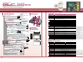
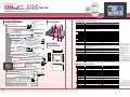
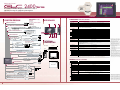


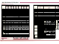
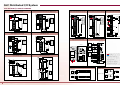


![特集 - JAあまるめ [余目町農業協同組合]](http://vs1.manualzilla.com/store/data/006585311_3-f45e24dbdf4032496a7ab6e9c6eb5765-150x150.png)