1
Falcon® 4400 Series
with Windows® CE
Falcon 4410
26-Key model
Falcon 4420
48-Key model
Falcon 4410
52-Key NU model
Product Reference Guide
PSC Inc
959 Terry Street
Eugene, Oregon 97402
Telephone: (541) 683-5700
Fax: (541) 345-7140
An Unpublished Work - All rights reserved. No part of the contents of this documentation or the procedures
described therein may be reproduced or transmitted in any form or by any means without prior written permission of
PSC Inc. or its wholly owned subsidiaries ("PSC"). Owners of PSC products are hereby granted a non-exclusive,
revocable license to reproduce and transmit this documentation for the purchaser's own internal business purposes. Purchaser shall not remove or alter any proprietary notices, including copyright notices, contained in this
documentation and shall ensure that all notices appear on any reproductions of the documentation.
Should future revisions of this manual be published, you can acquire printed versions by contacting your PSC representative. Electronic versions may either be downloadable from the PSC website (www.psc.com) or provided on
appropriate media. If you visit our website and would like to make comments or suggestions about this or other
PSC publications, please let us know via the “Contact PSC” page.
Disclaimer
PSC has taken reasonable measures to provide information in this manual that is complete and accurate, however,
PSC reserves the right to change any specification at any time without prior notice.
PSC is a registered trademark of PSC Inc. The PSC logo is a trademark of PSC. All other trademarks and trade
names referred to herein are property of their respective owners.
Falcon® is a registered trademark of PSC Inc. and of its wholly owned subsidiaries.
Microsoft Windows®, Windows® 2000, Windows®CE, Windows® NT, and Windows® XP are registered trademarks of
Microsoft Corporation.
Patents
This product may be covered by one or more of the following patents: 4603262 • 4639606 • 4652750 • 4672215 • 4699447 • 4709369 •
4749879 4786798 • 4792666 • 4794240 • 4798943 • 4799164 • 4820911 • 4845349 • 4861972 • 4861973 • 4866257 • 4868836 •
4879456 • 4939355 • 4939356 • 4943127 • 4963719 • 4971176 • 4971177 • 4991692 • 5001406 • 5015831 • 5019697 • 5019698 •
5086879 • 5115120 • 5144118 • 5146463 • 5179270 • 5198649 • 5200597 • 5202784 • 5208449 • 5210397 • 5212371 • 5212372 •
5214270 • 5229590 • 5231293 • 5232185 • 5233169 • 5235168 • 5237161 • 5237162 • 5239165 • 5247161 • 5256864 • 5258604 •
5258699 • 5260554 • 5274219 • 5296689 • 5298728 • 5311000 • 5327451 • 5329103 • 5330370 • 5347113 • 5347121 • 5371361 •
5382783 • 5386105 • 5389917 • 5410108 • 5420410 • 5422472 • 5426507 • 5438187 • 5440110 • 5440111 • 5446271 • 5446749 •
5448050 • 5463211 • 5475206 • 5475207 • 5479011 • 5481098 • 5491328 • 5493108 • 5504350 • 5508505 • 5512740 • 5541397 •
5552593 • 5557095 • 5563402 • 5565668 • 5576531 • 5581707 • 5594231 • 5594441 • 5598070 • 5602376 • 5608201 • 5608399 •
5612529 • 5629510 • 5635699 • 5641958 • 5646391 • 5661435 • 5664231 • 5666045 • 5671374 • 5675138 • 5682028 • 5686716 •
5696370 • 5703347 • 5705802 • 5714750 • 5717194 • 5723852 • 5750976 • 5767502 • 5770847 • 5786581 • 5786585 • 5787103 •
5789732 • 5796222 • 5804809 • 5814803 • 5814804 • 5821721 • 5822343 • 5825009 • 5834708 • 5834750 • 5837983 • 5837988 •
5852286 • 5864129 • 5869827 • 5874722 • 5883370 • 5905249 • 5907147 • 5923023 • 5925868 • 5929421 • 5945670 • 5959284 •
5962838 • 5979769 • 6000619 • 6006991 • 6012639 • 6016135 • 6024284 • 6041374 • 6042012 • 6045044 • 6047889 • 6047894 •
6056198 • 6065676 • 6069696 • 6073849 • 6073851 • 6094288 • 6112993 • 6129279 • 6129282 • 6134039 • 6142376 • 6152368 •
6152372 • 6155488 • 6166375 • 6169614 • 6173894 • 6176429 • 6188500 • 6189784 • 6213397 • 6223986 • 6230975 • 6230976 •
6237852 • 6244510 • 6259545 • 6260763 • 6266175 • 6273336 • 6276605 • 6279829 • 6290134 • 6290135 • 6293467 • 6303927 •
6311895 • 6318634 • 6328216 • 6332576 • 6332577 • 6343741 • 6454168 • 6478224 • 6568598 • 6578765 • 6705527 • 6974084 •
6991169 •7051940 • AU703547 • D312631 • D313590 • D320011 • D320012 • D323492 • D330707 • D330708 • D349109 • D350127 •
D350735 • D351149 • D351150 • D352936 • D352937 • D352938 • D352939 • D358588 • D361565 • D372234 • D374630 • D374869 •
D375493 • D376357 • D377345 • D377346 • D377347 • D377348 • D388075 • D446524 • EP0256296 • EP0260155 • EP0260156 •
EP0295936 • EP0325469 • EP0349770 • EP0368254 • EP0442215 • EP0498366 • EP0531645 • EP0663643 • EP0698251 •
GB2252333 • GB2284086 • GB2301691 • GB2304954 • GB2307093 • GB2308267 • GB2308678 • GB2319103 • GB2333163 •
GB2343079 • GB2344486 • GB2345568 • GB2354340 • ISR107546 • ISR118507 • ISR118508 • JP1962823 • JP1971216 • JP2513442
• JP2732459 • JP2829331 • JP2953593 • JP2964278 • MEX185552 • MEX187245 • RE37166 • Other Patents Pending
Table of Contents
Preface: About this Guide .................................................................................. vii
Chapter 1. Batteries and Power ........................................................................ 1-1
Overview ...................................................................................................................1-1
Suspend Mode ............................................................................................................1-1
Suspending ..........................................................................................................1-1
Resuming ............................................................................................................1-2
Battery Warnings and Cautions .....................................................................................1-2
Battery Disposal ........................................................................................................1-4
Chapter 2. Configuring the Falcon..................................................................... 2-1
Overview ...................................................................................................................2-1
Aironet Client Utility ....................................................................................................2-2
Backlight ...................................................................................................................2-2
Certificates .................................................................................................................2-3
Date and Time ............................................................................................................2-4
Decoding ...................................................................................................................2-4
Configuration Control Panels ...................................................................................2-5
Settings ............................................................................................................. 2-11
Display Configuration ................................................................................................. 2-11
Background ........................................................................................................ 2-11
Appearance ........................................................................................................ 2-12
Falcon Config ............................................................................................................ 2-12
Imager .................................................................................................................... 2-12
Imaging Overview ............................................................................................... 2-12
Image Capture ................................................................................................... 2-13
Image File ......................................................................................................... 2-14
Image Size ........................................................................................................ 2-15
Image Settings ................................................................................................... 2-16
Sample Imager Settings ...................................................................................... 2-16
Input Panel Properties ............................................................................................... 2-17
Internet Options ....................................................................................................... 2-18
Keyboard Configuration ............................................................................................. 2-21
26-Key Keypad ................................................................................................... 2-21
48, 52 and 52-Key NU Keypads ............................................................................ 2-21
Network and Dialup ................................................................................................... 2-23
Owner ..................................................................................................................... 2-24
Password ................................................................................................................. 2-24
PC Connection .......................................................................................................... 2-25
Product Reference Guide
i
Persistent Registry .................................................................................................... 2-25
Power Configuration .................................................................................................. 2-26
Regional Settings ...................................................................................................... 2-27
Remove Programs ..................................................................................................... 2-28
Storage Properties .................................................................................................... 2-28
Stylus Calibration ...................................................................................................... 2-29
System Properties .................................................................................................... 2-31
General Tab ...................................................................................................... 2-31
Firmware Tab .................................................................................................... 2-31
Memory Configuration ......................................................................................... 2-32
Device Name ...................................................................................................... 2-33
Copyrights ......................................................................................................... 2-33
Volume and Sounds ................................................................................................... 2-34
Chapter 3. Software Applications...................................................................... 3-1
Overview ...................................................................................................................3-1
Inbox ........................................................................................................................3-2
Internet Explorer ........................................................................................................3-3
Media Player ...............................................................................................................3-4
WordPad ....................................................................................................................3-4
Installing Programs .....................................................................................................3-4
Using an Installation Wizard ...................................................................................3-5
Installing Programs Manually ..................................................................................3-5
Using Windows Explorer to Add to the Start Menu .....................................................3-6
Using ActiveSync to Add to the Start Menu ...............................................................3-6
Removing Programs ....................................................................................................3-7
Firmware Update Utility ...............................................................................................3-7
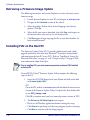
Retrieving a Firmware Image Update .......................................................................3-8
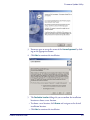
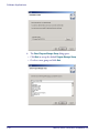
Installing FUU on the Host PC .................................................................................3-8
Updating the Falcon Firmware ............................................................................... 3-12
Restoring Falcon Firmware ................................................................................... 3-14
AutoStart ................................................................................................................. 3-15
Installing CAB files .............................................................................................. 3-16
Autostart.ini ....................................................................................................... 3-17
Chapter 4. Networks, Communications,
and Connections ............................................................................................... 4-1
Overview ...................................................................................................................4-1
Installing & Setting Up Microsoft ActiveSync ...................................................................4-1
Installing Microsoft ActiveSync ................................................................................4-2
Setting Up ActiveSync ...........................................................................................4-4
Installing the USB Driver ..............................................................................................4-5
Using ActiveSync ........................................................................................................4-6
File Synchronizing using ActiveSync ........................................................................4-6
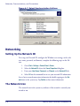
Networking ................................................................................................................4-8
Setting Up the Network ID .....................................................................................4-8
The Network Icon .................................................................................................4-8
Network and Dialup Connections .............................................................................4-9
Product Reference Guide
ii
SNMP ...................................................................................................................... 4-10
Appendix A. Accessories .................................................................................. A-1
Overview ...................................................................................................................A-1
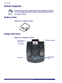
Power Supplies ...........................................................................................................A-2
Battery Pack ........................................................................................................A-2
Single-Slot Dock ...................................................................................................A-2
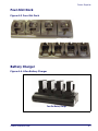
Four-Slot Dock .....................................................................................................A-3
Battery Charger ....................................................................................................A-3
USB Cable ............................................................................................................A-4
Serial Charging Cable ............................................................................................A-4
Printer Cable ........................................................................................................A-4
Serial Printer Adapter ............................................................................................A-4
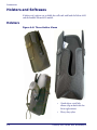
Holsters and Softcases .................................................................................................A-6
Holsters ..............................................................................................................A-6
Softcases .............................................................................................................A-7
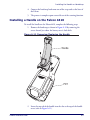
Installing the Handle or Handstrap ................................................................................A-8
Installing the Handstrap on the Falcon 4420 .............................................................A-8
Installing a Handle on the Falcon 4410 .....................................................................A-9
Tethered Stylus ........................................................................................................ A-10
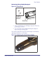
Installing a Tethered Stylus .................................................................................. A-10
Removing a Tethered Stylus ................................................................................. A-11
Appendix B. Falcon® Desktop Utility for Windows® CE ................................... B-1
Overview ...................................................................................................................B-1
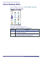
Falcon Desktop Utility ..................................................................................................B-2
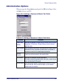
Administrative Options ...........................................................................................B-3
Setting a Password ................................................................................................B-4
Changing a Password ............................................................................................B-4
Removing a Password ............................................................................................B-4
Password Request Dialog Box .................................................................................B-4
Setting Hot Keys ..................................................................................................B-5
Internet Explorer Configuration ...............................................................................B-8
Modifying Windows Controls ................................................................................. B-10
Application Selector ................................................................................................... B-11
Add Application ................................................................................................... B-12
Application Selector ................................................................................................... B-14
Application Switcher User Interface ............................................................................. B-15
Appendix C. Configuring the Web Server ......................................................... C-1
Overview ...................................................................................................................C-1
Enabling the Web Server ..............................................................................................C-1
Setting Up a User ........................................................................................................C-2
Testing the Web Server ...............................................................................................C-3
Launching the Network Administration Page ...................................................................C-4
Web Server Registry Settings .......................................................................................C-4
Creating and Using an ISAPI Service ..............................................................................C-6
Product Reference Guide
iii
Appendix D. SNMP Interface............................................................................ D-1
Overview .................................................................................................................. D-1
SNMP Concepts ................................................................................................... D-1
MIB Files ............................................................................................................ D-1
Additional Resources ............................................................................................ D-2
Appendix E. Cable & Connector Configurations ................................................. E-1
Introduction ...............................................................................................................E-1
General Specifications .................................................................................................E-1
Wire Requirements ................................................................................................E-1
Supply Voltage .....................................................................................................E-1
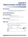
USB Cable ..................................................................................................................E-1
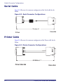
Serial Cable ................................................................................................................E-2
Printer Cable ..............................................................................................................E-2
Appendix F. Programming Parameters ............................................................. F-1
Overview ................................................................................................................... F-1
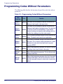
Programming Codes Without Parameters ........................................................................ F-2
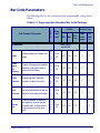
Bar Code Parameters ................................................................................................... F-3
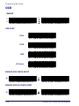
OCR Configuration ..................................................................................................... F-37
OCR Data Output ................................................................................................ F-37
OCR Templates ................................................................................................... F-37
OCR Check Characters ......................................................................................... F-42
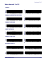
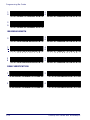
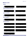
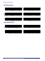
Appendix G. Programming Bar Codes .............................................................. G-1
Overview .................................................................................................................. G-1
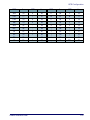
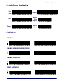
Predefined Defaults ................................................................................................... G-3
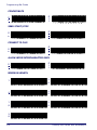
Codabar .................................................................................................................... G-3
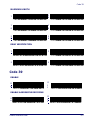
Code 39 .................................................................................................................... G-5
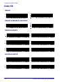
Code 93 .................................................................................................................... G-8
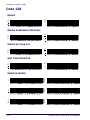
Code 128 .................................................................................................................G-10
EAN-13 ....................................................................................................................G-12
EAN-8 .....................................................................................................................G-14
Interleaved 2 of 5 .....................................................................................................G-15
Matrix 2 of 5 ............................................................................................................G-17
MSI .........................................................................................................................G-19
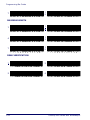
Pharmacode 39 (Code 32) ..........................................................................................G-21
RSS-14 ....................................................................................................................G-21
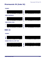
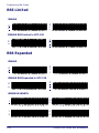
RSS Limited .............................................................................................................G-22
RSS Expanded ..........................................................................................................G-22
Standard 2 of 5 ........................................................................................................G-24
Trioptic ....................................................................................................................G-26
UPC-A .....................................................................................................................G-26
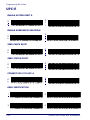
UPC-E ......................................................................................................................G-28
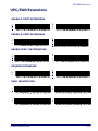
UPC/EAN Extensions ..................................................................................................G-29
2D Symbologies ........................................................................................................G-30
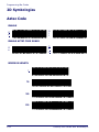
Aztec Code ...............................................................................................................G-30
Product Reference Guide
iv
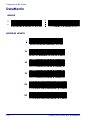
DataMatrix ...............................................................................................................G-32
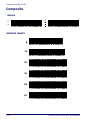
Composite ................................................................................................................G-34
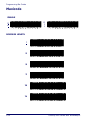
Maxicode .................................................................................................................G-36
OCR ........................................................................................................................G-38
PDF-417 ..................................................................................................................G-39
MicroPDF-417 ...........................................................................................................G-41
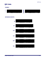
QR Code ..................................................................................................................G-43
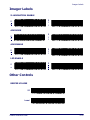
Imager Labels ..........................................................................................................G-45
Other Controls ..........................................................................................................G-45
Appendix H. Glossary....................................................................................... H-1
Index............................................................................................................. 1-xiii
Product Reference Guide
v
NOTES
Product Reference Guide
vi
Preface:
About this Guide
How to Use this Manual
This Product Reference Guide contains comprehensive basic user
instructions for the Falcon 4400 Series mobile computer software,
batteries, dock, serial cable, data transfer, as well as advanced user
information such as bar code configuration and parameters. This section
of the manual provides an overview of the manual’s contents and
organization.
Document Overview
This document contains the following material:
Product Reference Guide
•
This Preface provides an overview of the contents for each chapter, and describes document style conventions.
•
Chapter 1, Batteries and Power, discusses checking battery power,
power conservation, battery installation, battery charging with a
dock or battery charger, battery storage, battery disposal, and
resetting the mobile computer.
•
Chapter 2, Configuring the Falcon, uses the control panels to
adjust touchscreen calibration, date and time, display backlight/
contrast, volume/sounds, scanner, power, and memory.
•
Chapter 3, Software Applications, covers flash memory, installing, selecting, using, and removing applications, entering data,
and using the soft input panel with Inbox, Internet Explorer, and
Word Pad.
•
Chapter 4, Networks, Communications, and Connections,
describes installing, setting up, and using ActiveSync and Networking.
•
Appendix A, Accessories, describes the Accessories, such as docks,
battery chargers, holsters, and soft cases available for the Falcon.
vii
Preface
•
Appendix B, Falcon® Desktop Utility (FDU) allows PSC Windows administrators to configure Windows®CE Falcons to control individual user access.
•
Appendix C, Configuring the Web Server, describes configuring
the Falcon to work with a Web Server.
•
Appendix D, SNMP Interface, describes SNMP (Simple Network Management Protocol) concepts, MIB (Management Information Base) files, and provides additional resources.
•
Appendix E, Cable and Connector Configurations contains
pinout information, to create standard interface cables for use in
interconnecting the Dock to power and/or peripheral devices.
•
Appendix F, Programming Parameters, provides the programmable settings for the Falcon.
•
Appendix G, Programming Bar Codes, provides bar codes for
common setup parameters for programming the Falcon.
•
Appendix H, Maintenance, describes Falcon maintenance, provides a list of error messages, and gives information on contacting
PSC for technical support.
•
Appendix H, Glossary, is a glossary of terms used in this manual
that you may not be familiar with that are specific to Windows®CE and the mobile computer.
Registering Your PSC Product
PSC values your feedback. Please take a few moments and complete the
Product Registration form located on our website (www.psc.com).
Registering your products ensures that you will be informed of the latest
product news, technical specifications, software updates and other future
developments from PSC.
viii
Falcon® 4400 Series with Windows®CE
Document Conventions
Document Conventions
Formatting conventions are used throughout this guide to provide a
consistent method for representing screen shots, command entries, and
keyboard characters. This guide also provides special conventions for
notes and cautions, information of high interest.
NOTES contain information necessary for properly diagnosing, repairing and
operating the terminal.
The CAUTION symbol advises you of actions that could damage equipment or
property.
CAUTION
A WARNING symbol calls attention to actions that could result in personal injury.
WARNING
Keystrokes. Filenames, paths, field selections from a pull-down list,
and data or keystrokes entered by the user are shown in this
monospaced typeface.
Windows Controls. Windows controls including command bar
sequences, prompts, dialog boxes, fields, pull-down lists, check boxes and
radio buttons are printed in this bold typeface.
Portable Keys
Keys on the Falcon are bracketed by “greater than” and “less than” symbols
(< >) to distinguish them from keys on the PC.
<F1> — <F19> Keys. The Function keys, such as <F1>, refers only
to keys on the Falcon.
<ENTER> Key. To differentiate the <ENTER> key on the portable from
the Enter key on the PC’s keyboard, portable keys are formatted with
“greater than” and “less than” symbols: <ENTER>.
Product Reference Guide
ix
Preface
Stylus Actions
Stylus actions apply to the Falcon only; most PCs use a mouse as an input
device.
Tap or Select. Tap the display screen once with the stylus to activate a
specific button or select an item from a pull-down list.
Double-Tap. Tap the stylus twice rapidly in the same location to open
an application.
Tap and Hold. Tap and hold the stylus to view the context menu.
Refer to the Quick Reference Guide (QRG) for more information on
using a stylus with the Falcon.
Mouse Actions
Applies to the software installation portions of this document using a PC;
the Falcon comes equipped with a stylus. Refer to Stylus Actions (above),
or see the QRG for more information.
Click or Select. Press and immediately release the left mouse button
without moving the mouse. Clicking is used to select specific buttons on
various forms and tables.
Double-Click. Click the left mouse button twice in rapid succession.
Used to initiate an application.
Right Click. Press and hold the right mouse button without moving
the mouse.
Select. Click and release the left mouse button to choose an item or
items from a pull-down list.
x
Falcon® 4400 Series with Windows®CE
Chapter 1
Batteries and Power
Overview
This section contains the following topics:
•
"Suspend Mode" starting on page 1-1
•
"Battery Warnings and Cautions" on page 1-2
•
"Battery Disposal" starting on page 1-4.
Suspend Mode
The Falcon will go into a suspend or sleep mode when it is idle for a period of
time. This duration can be customized using the Power control panel (refer to
"Power Off Tab" on page 2-26. Suspend mode works and looks just like you
have turned the unit off. Press <Power> to suspend (put to sleep) the Falcon.
Press <Power> again for the Falcon to resume its previous state.
Use the Battery Power control panel to set the idle duration and the initiation
of suspend mode. These features save battery power when the Falcon is not in
use. Refer to "Power Off Tab" on page 2-26 for more information.
Suspending
The following conditions will put the unit into suspend (sleep) mode:
1. When the unit is on, press <Power> for 0.5 second to initiate suspend
mode.
2. When the sleep timer expires, indicating that there has been no use
for a specified period of time.
3. A discharged battery pack.
Product Reference Guide
1-1
Batteries and Power
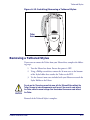
Resuming
Use one of the following methods to resume (wake up the Falcon):
•
Press <Power> to resume (wake up).
•
Put the Falcon into a dock.
•
Press the <Scan Trigger> to wake up the unit (handled version only).
When a battery pack is fully discharged while the unit is in suspend mode, the
Falcon remains in the suspended mode until the battery pack is charged or
external power is supplied via the dock or a power cable.
Battery Warnings and Cautions
Do not discharge the battery using any device except for the Falcon. When the
battery is used in devices other than the Falcon, it may damage the battery or
reduce its life expectancy. If the device causes an abnormal current to flow, it may
WARNING cause the battery to become hot, explode or ignite and cause serious injury.
Lithium-ion battery packs may get hot, explode or ignite and cause serious injury
if exposed to abusive conditions. Be sure to follow the safety warnings listed
below:
•
Do not place the battery pack in fire or heat.
•
Do not install the battery pack backwards so the polarity is reversed.
•
Do not connect the positive terminal and negative terminal of the battery pack
to each other with any metal object (such as wire).
•
Do not carry or store the battery pack together with metal objects.
•
Do not pierce the battery pack with nails, strike it with a hammer, step on it or
otherwise subject it to strong impacts or shocks.
•
Do not solder directly onto the battery pack.
•
Do not expose the battery pack to liquids, or allow the battery to get wet.
In the event the battery pack leaks and the fluid gets into your eye, do not rub the
eye. Rinse well with water and immediately seek medical care. If left untreated, the
battery fluid could cause damage to the eye.
1-2
Falcon® 4400 Series with Windows® CE
Battery Warnings and Cautions
Always charge the battery at 32°–113°F (0°–45°C) temperature range.
CAUTION
If you remove the battery pack or it becomes completely discharged, there is a 30
minute window in which to insert a charged battery pack before the backup battery fails. If your backup battery completely discharges, the contents of the RAM
memory will be lost. If your back-up battery is less than fully charged, there is proportionally smaller window of time available.
Use only the authorized power supplies, battery pack, chargers, and docks supplied by your PSC reseller. The use of any other power supplies can damage the
Falcon and void your warranty. Refer to Appendix A for the correct Power Supplies and Accessories.
Do not disassemble or modify the battery. The battery contains safety and protection devices, which, if damaged, may cause the battery to generate heat, explode
or ignite.
Do not place the battery in or near fire, on stoves or other high temperature locations. Do not place the battery in direct sunlight, or use or store the battery inside
unventilated areas such as cars in hot weather. Doing so may cause the battery to
generate heat, explode or ignite. Using the battery in this manner may also result
in a loss of performance and a shortened life expectancy.
Do not place the battery in microwave ovens, high-pressure containers or on
induction cookware.
Immediately discontinue use of the battery if, while using, charging or storing the
battery, the battery emits an unusual smell, feels hot, changes color or shape, or
appears abnormal in any other way.
PSC recommends annual replacement of rechargeable battery packs to ensure
maximum performance.
Product Reference Guide
1-3
Batteries and Power
Battery Disposal
If you must dispose of a battery pack, please follow the CAUTIONS below:
CAUTION
Use only a battery pack supplied by a PSC reseller for this device.The use of other
battery supplies can damage the Falcon and void your warranty. Contact your
reseller to for the correct power supplies; view your options under "Battery Pack"
on page A-2 or the PSC price book at www.psc.com.
When the battery pack is worn out, insulate the battery pack terminals with adhesive tape or similar materials before disposal.
CAUTION
Recycle Lithium-Ion Batteries.
Do not throw Lithium-Ion Batteries in the trash
Please reference your local regulations for any further guidelines about battery
disposal.
1-4
Falcon® 4400 Series with Windows® CE
Chapter 2
Configuring the Falcon
Overview
This section contains the following topics
on configuring your Falcon. Most control
panels are accessed by selecting/tapping
Start > Settings > Control Panel.
•
"Aironet Client Utility" on page 2-2
(only on units with Cisco radio)
•
"Backlight" on page 2-2
•
"Certificates" on page 2-3
•
"Date and Time" on page 2-4
•
"Decoding" on page 2-4
•
"Display Configuration" on
page 2-11
•
"Falcon Config" on page 2-12
•
"Imager" on page 2-12
•
"Input Panel Properties" on
page 2-17
•
"Internet Options" on page 2-18
•
"Keyboard Configuration" on
page 2-21
•
"Network and Dialup" on page 2-23
•
"Owner" on page 2-24
•
"Password" on page 2-24
•
"PC Connection" on page 2-25
•
"PC Connection" on page 2-25
Product Reference Guide
Control Panels
2-1
Configuring the Falcon
•
"Power Configuration" on page 2-26
•
"Regional Settings" on page 2-27
•
"Remove Programs" on page 2-28
•
"Storage Properties" on page 2-28
•
"Stylus Calibration" on page 2-29
•
"System Properties" on page 2-31
•
"Volume and Sounds" on page 2-34
Aironet Client Utility
See "Network and Dialup Connections" on page 4-9.
Backlight
Increasing backlight brightness can cause the battery pack to discharge at a faster
rate. The battery discharge rate decreases with a decrease in backlight usage.
To change the Backlight settings, complete the following steps:
1. Select Start > Settings > Control Panel > Backlight to open the Backlight
control panel. Some Falcon keypads also provide keyboard shortcuts
to launch the Backlight control panel:
•
On the 26-key model press: <Fn>+<Backlight> (
).
•
•
On the 48-key model press: <Fn>+<Backlight> (
On the 52-key model press: <Fn>+< . >.
).
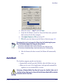
2. On the Brightness tab (refer to Figure 2-1), select one of the five (5)
radio buttons to adjust the brightness to the desired setting by tapping
it with the stylus. You can also use the <UP> and <DOWN> arrow keys
to adjust this setting.
3. Auto Power-Save dims (rather than turning off ) the backlight after 15
seconds of inactivity. This features does not change the behavior of
the Auto-Off Settings. (Refer to "Power Configuration" on
page 2-26).
2-2
Falcon® 4400 Series with Windows® CE
Certificates
Figure 2-1. Backlight Control Panel & Brightness
4. On the Auto-Off tab, enable the desired option checkbox and select the
desired options from the pull-down lists (refer to Figure 2-1).
5. On the Activation tab, just tap the checkbox(es) to enable or disable
them (refer to Figure 2-1):
• Set the backlight to turn on automatically when any key is pressed
or the touchscreen is tapped, either while on battery or external
power.
• Turn on the backlight when the trigger is pulled.
• Deselect Launch Control Panel from the Keyboard to turn off the
ability to open the Backlight control panel with a key sequence.
Using Auto-on while running from battery power will cause the battery pack to
discharge at a faster rate. The battery discharge rate decreases with a decrease in
backlight usage.
6. To exit and save your modifications, tap OK on the command bar, or
press <Enter> on the keypad.
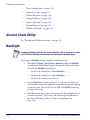
Certificates
Certificates are used by some applications for establishing trust and to secure
communications. See the Microsoft Windows CE help on your Falcon unit for
further information about Certificates.
Product Reference Guide
2-3
Configuring the Falcon
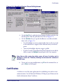
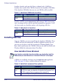
Date and Time
In this control panel, you can change the year, month, date, time, time zone,
or select automatic adjust for Daylight Savings Time. To set or change the date
and time:
1. Select Start > Settings > Control
Panel > Date/Time.
2. Select the month to open a pulldown list of months or tap the
arrow buttons on either side of
the month to increase or decrease
the month.
3. To change the year, select the year
to open a numeric dial. Select the
up arrow to increase the value;
select the down arrow to decrease
the value. Or you can type a new
year value in the field.
4. To change the time, select the hour, minute, seconds, or AM/PM and
select the up arrow to increase the value; select/tap the down arrow to
decrease the value. Or you can type a new time value in the field.
5. Select your correct time zone from the pull-down list.
6. To automatically adjust the clock for Daylight Savings Time, enable
the checkbox at the bottom of the screen.
7. Select Apply to save your changes and make additional modifications.
• Select OK to save your changes and exit Date/Time Properties.
• Select/tap the close button to exit without saving your changes.
Decoding
You can configure the Falcon’s decoding options by tapping on Start > Settings
> Control Panel > Decoding. Decoder configuration can also be accomplished for
large numbers of terminals using FMU (Falcon Management Utility).
There are two sections in the Decoding control panel, each containing additional pages. There are six General Configuration pages and multiple Bar
Code symbology pages.
2-4
Falcon® 4400 Series with Windows® CE
Decoding
Other decoding parameters are described in Programming Parameters, starting
on page F-1; bar code settings are provided in Programming Bar Codes, starting
on page G-1.
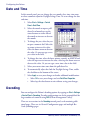
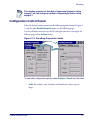
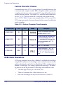
Configuration Control Panels
Select the desired configuration from the following options shown in Figure 22, and the other Decoding Properties figures on the following pages.
Use the pull-down menus or tap the left and right arrow keys to navigate the
different pages of the Configure utility.
Figure 2-2. Decoding Properties: Audio
To view other configuration options, select Configure > General from the menu
•
Product Reference Guide
Audio: Sets volume, tone, duration, and number of various types of
beeps.
2-5
Configuring the Falcon
Figure 2-3. Decoding Properties: General Options
To view other configuration options, select Configure > General from the menu
•
General Options: Select from Label Programming Enable, Symbology
IDs, Label Prefix, Label Suffix, and Data Separator options.
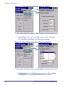
Figure 2-4. Decoding Properties: Decoding Options
To view other configuration options, select Configure > General from the menu
•
2-6
Decoding Options: Set the User ID character associated with a symbology,
the Redundancy and select Aggressive Decoding when available.
Falcon® 4400 Series with Windows® CE
Decoding
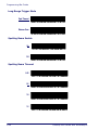
Figure 2-5. Decoding Properties: Trigger Options
To view other configuration options, select Configure > General from the menu
•
Trigger Options: Select from Pistol Trigger and Scan Key enable for Bar
code, Image, and RFID (available in future versions). Select the desired
radio buttons to define the button functions. Available items will vary
depending on the model.
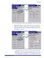
Figure 2-6. Decoding Properties: Imager Options
To view other configuration options, select Configure > General from the menu
•
Imager Options: (Models with Imaging module only). Enable/Disable
Illumination and the Aiming Beam for Imaging. Mode lets you select
between Concurrent (the aiming beam and the illumination beam turn
Product Reference Guide
2-7
Configuring the Falcon
on at once); and Interlaced (the aimer beam and illumination alternate
being on). Set Brightness and Timeout properties using the sliders.
Figure 2-7. Decoding Properties: Devices
To view other configuration options, select Configure > General from the menu
•
Devices: Enable the keyboard wedge for bar code scanner, Magnetic
Stripe Reader, RFID, and enable Read-Ahead for attached devices.
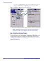
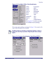
Bar Code Symbology Pages
Use the pull-down menus from Configure > 1D Bar Code or 2D Bar Code, or tap
the left and right arrow keys to navigate the different pages of the bar code
symbology pages. Each bar code symbology opens to its own page, as shown in
Figure 2-9 on page 2-9.
2-8
Falcon® 4400 Series with Windows® CE
Decoding
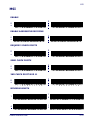
Figure 2-8. Available 1D Bar Code Symbologies
Codabar
Pharmacode 39
Code 39
RSS-14
Code 93
RSS-Limited
Code 128
RSS-Expanded
EAN-13
Standard 2/5
EAN-8
Trioptic
Interleaved 2/5
UPC-A
Matrix 2/5
UPC-E
MSI
UPC/EAN Extensions
See Appendix G for details on parameters available for each symbology.
Refer to the sample symbology control panels in Figure 2-9 for examples of the
types of fields and options you can modify.
Decoding parameters are described in Programming Parameters, starting on
page F-1; bar code settings are provided in Programming Bar Codes, starting on
page G-1.
Figure 2-9. Common Symbologies: Code 39 and UPC-A
Product Reference Guide
2-9
Configuring the Falcon
•
Code 39: Select from enable, min/max lengths, enable checksum, send
checksum, and Full ASCII conversion.
•
UPC-A: Select from Enable, Send Check Digit, and Send System Digit.
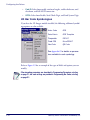
2D Bar Code Symbologies
If you have the 2D Imager module installed, the following additional symbology options are also available:
Aztec Code
OCR
Data Matrix
OCR Template
Composite
PDF417
Code 128
MicroPDF417
MaxiCode
QR Code
See Appendix G for details on parameters available for each symbology.
Refer to Figure 2-9 for an example of the types of fields and options you can
modify.
Other decoding parameters are described in Programming Parameters, starting
on page F-1; bar code settings are provided in Programming Bar Codes, starting
on page G-1.
2-10
Falcon® 4400 Series with Windows® CE
Display Configuration
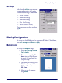
Settings
Select from the Settings menu to restore
previous configurations and/or other
available default settings. Choose from:
•
Factory Defaults
•
Minimum Settings
•
Maximum Settings
•
Save (New Settings)
•
Reverts to Saved Settings
The settings are saved when you select/
tap OK.
Display Configuration
To change the default Background or Appearance (Windows Color Scheme),
select Start > Settings > Control Panel > Display.
Background
To change the Background image:
1. Select Start > Settings > Control
Panel > Display.
2. Place a new image in the Windows directory. This file must
be exactly 240 pixels wide by
320 pixels high.
3. The current file is located in the
Windows directory with the
PSC logo file named
PSC.bmp.
4. Select the new file name by
using Browse.
Product Reference Guide
2-11
Configuring the Falcon
Appearance
To change the default Windows color
scheme:
1. Tap the Appearance tab.
2. Tap the Scheme pull-down list
and select a new Windows color
scheme if desired.
3. Tap OK on the control bar, or
press <Enter> on the keypad.
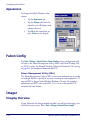
Falcon Config
Tap Start > Settings > Control Panel > Falcon Config to access configuration utilities such as the Falcon Management Utility (FMU) and Falcon Desktop Utility (FDU) settings. See Falcon® Desktop Utility for Windows® CE, starting
on page B-1, for complete information on FDU.
Falcon Management Utility (FMU)
The Falcon Management Utility (FMU) is the easiest method to use to configure multiple Falcons, especially if you have an enterprise-wide deployment. A
copy of FMU is shipped with all Falcon Windows CE units. For complete
information on FMU, refer to the FMU User’s Guide on the product CD
included with your Falcon.
Imager
Imaging Overview
If your Falcon has the Imager module installed, you will see the Imaging Control Panel on your screen. Select Start > Settings > Control Panel > Imager.
2-12
Falcon® 4400 Series with Windows® CE
Imager
See "Sample Imager Settings" on page 2-16 to view sample settings for different conditions.
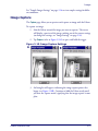
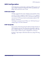
Image Capture
The Capture page allows you to preview and capture an image with the Falcon.
To capture an image:
1. Aim the Falcon toward the image you want to capture. The screen
will display a preview of the image, making use of the current settings
(to change the settings, see "Image Settings" on page 2-16).
2. Tap Capture (refer to Figure 2-10A) or press and hold the trigger.
Figure 2-10. Image Capture Settings
A
B
3. An hourglass will appear, indicating the image capture process has
begun (see Figure 2-10B). Continue to hold the Falcon steady until
you hear the capture sound, signifying that the image capture is complete.
Product Reference Guide
2-13
Configuring the Falcon
4. A File Save message showing the
image file name will appear,
unless that option has been previously deselected in the File settings (in that case, the file will
automatically save without
prompting). See "Image File" on
page 2-14, to change settings.
5. Tap Yes to save the image, or No
to discard it.
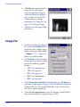
Image File
1. Specify where you want images to
be saved in the File Folder field. If
you do not select a folder, images
will be saved to the default folder
“\Images.” Use … (browse) to
browse to a different folder.
2. Use File Format to select the image
format you want. You can choose
between the following graphics
formats:
• TIFF (1-bit monochrome)
• TIFF (8-bit grayscale)
• JPEG (8-bit grayscale)
• BMP (1-bit monochrome)
• BMP (8-bit grayscale)
3. Check Confirm before Saving File to automatically get a File Save message when saving images (see Figure 2-10B). If unchecked, the file will
automatically save to the specified file folder (at the root of the Falcon’s drive) without prompting.
4. Check Exit after Image Capture to cause the Imaging Control Panel to
close automatically after saving the image to a file.
2-14
Falcon® 4400 Series with Windows® CE
Imager
5. Enable Long Range Filter enhances pictures taken from very long distances (greater than 10 feet or 3 meters).
6. Enable Aimer Illumination turns on the aimer LEDs to provide more
light for an image capture.
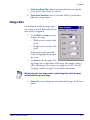
Image Size
On the Size tab, modify the image property settings as desired. Both keyboard and
stylus input are supported.
1. Use the Width and Height controls
to adjust the image.
• Width can be as much as 640
pixels.
• Height can be as much as 480
pixels.
Reducing the height and width
results in cropping of the image to
the center.
2. Use Scale to scale the image. Scaling changes the x,y dimensions of the image. For example, scaling a
640 x 480 image to 50% results in an image size of 320 x 240. See
"Imaging Controls" on page F-32, for further information.
Reducing the scale of an image results in reduced image size, which decreases
the time needed to capture an image.
3. Rotate allows you to change the orientation of the image, in 90° increments.
Product Reference Guide
2-15
Configuring the Falcon
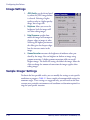
Image Settings
1. JPEG Quality sets the desired quality when the JPEG image format
is selected. Selecting a higher
quality results in a higher quality
image, but a larger file.
2. Brightness allows you to set the
brightness level the imager will
use when taking images.
3. Edge Sharpness specifies how
much the imager will attempt to
sharpen edges in images it takes.
Selecting the highest position on
the slider gives the sharpest edges,
but also increases noise in the
image.
4. Gamma Correction measures the brightness of midtone values produced by the image. You can brighten or darken an image using
gamma correction. A higher gamma correction yields an overall
brighter image. The lower the setting, the darker the image. Move the
slider to change the amount of correction the imager applies when
taking images.
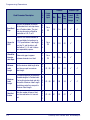
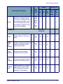
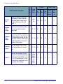
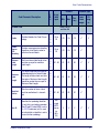
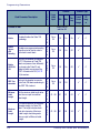
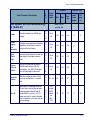
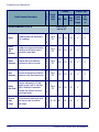
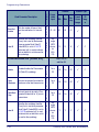
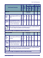
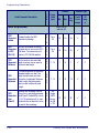
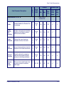
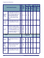
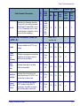
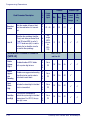
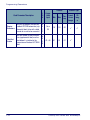
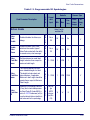
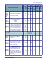
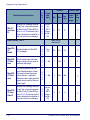
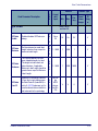
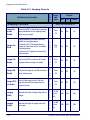
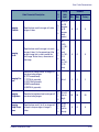
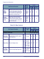
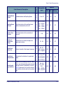
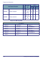
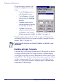
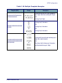
Sample Imager Settings
To obtain the best possible results, you can modify the settings to suit specific
conditions or purposes. Table 2-1 shows samples of recommended settings for
common usages. These settings are suggested only, you will need to take into
account your particular environment and conditions to determine optimal settings for your specific situation.
2-16
Falcon® 4400 Series with Windows® CE
Input Panel Properties
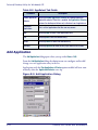
Table 2-1. Sample Imager Settings
Condition
Distance >10 ft (3 m)
Low light
Printed Text
Signature
Item
Recommended
Setting
Long Range filter
On
Illumination
Off
Illumination
On
Brightness
100%
Gamma Correction
20
Illumination
On
Sharpness
100%
File format
8-bit
Illumination
On
Sharpness
100%
File format
1-bit
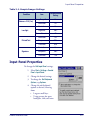
Input Panel Properties
To change the Soft Input Panel settings:
1. Select Start > Settings > Control
Panel > Input Panel.
2. Change the desired settings.
3. To change the Soft Keyboard
Options, tap Options.
4. Change the soft keyboard
options as desired, selecting
from:
• Large or small keys.
• Using gestures for space,
backspace, shift, and enter.
Product Reference Guide
2-17
Configuring the Falcon
5. To exit the Soft Keyboard
Options, tap OK on the control
bar, or press <Enter> on the keypad.
6. To exit Input Panel settings, tap
OK on the control bar, or press
<Enter> on the keypad.
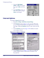
Internet Options
To change the Internet default settings:
1. Select Start > Settings > Control Panel > Internet Settings.
2. On the General tab (refer to Figure 2-11A), type in the URL of the
desired start page and the desired search engine. You can also select a
User Agent, change the Cache Size, clear the Cache, and clear the History.
3. On the Connection tab (refer to Figure 2-11B) modify the network
access settings as desired.
Figure 2-11. Internet Settings
A
B
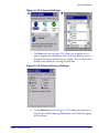
4. On the Security tab (refer to Figure 2-12A) add sites or modify the
security settings for Internet, Local intranet, Trusted Sites, and
Restricted Sites.
2-18
Falcon® 4400 Series with Windows® CE
Internet Options
Figure 2-12. Internet Settings
A
B
5. The Privacy tab (refer to Figure 2-13) allows you to modify the settings by tapping the radio buttons. You can Accept, Block or receive a
Prompt for First-party and Third-party Cookies. You can also Enable/
disable session cookies by selecting the check box.
Figure 2-13. Internet Privacy Settings
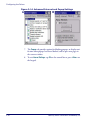
6. On the Advanced tab (refer to Figure 2-14A) modify the advanced settings for Accessibility, Browsing, Multimedia, and Security by tapping
the check boxes.
Product Reference Guide
2-19
Configuring the Falcon
Figure 2-14. Advanced Internet and Popup Settings
A
B
7. The Popups tab provides options for blocking popups, to display notification when popups have been blocked, and to open new pages in
the current window.
8. To exit Internet Settings, tap OK on the control bar or press <Enter> on
the keypad.
2-20
Falcon® 4400 Series with Windows® CE
Keyboard Configuration
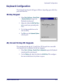
Keyboard Configuration
The keyboard control panel will appear different, depending upon which keypad your Falcon has.
26-Key Keypad
1. Select Start > Settings > Control Panel
> Keyboard Options to open the
Keyboard control panel.
2. Adjust the slider for Multi-Tap Timeout to match your personal preferences.
3. Use the box provided to test the
time-out delay.
4. Tap OK to exit the Keyboard Options
control panel.
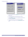
48, 52 and 52-Key NU Keypads
The control panels for the 48, 52 and 52-key NU keypads have some additional options and an additional tab for key mapping.
1. Select Start > Settings > Control Panel > Keyboard to open the Keyboard
control panel for your keypad.
2. On the Options tab, adjust the slider for Initial Delay. This configures
the time to hold down a key before it repeats.
Product Reference Guide
2-21
Configuring the Falcon
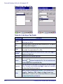
Figure 2-15. 48-Key or 52-Key Keypad Control Panels
3. You can also adjust the slider for Repeat Rate. This configures how fast
the keys repeat.
4. Use the box provided to test the selected repeat rate setting.
5. On the Load Map tab, you can select a keyboard key-map by browsing,
or change to the Default Map.
6. Use the box provided to test the current keyboard mapping.
7. Tap OK to save your changes and exit the Keyboard Options control
panel.
2-22
Falcon® 4400 Series with Windows® CE
Network and Dialup
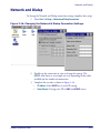
Network and Dialup
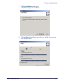
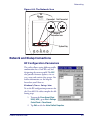
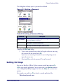
To change the Network and Dialup connection settings, complete these steps:
1. Select Start > Settings > Network and Dialup Connections.
Figure 2-16. Changing the Network & Dialup Connection Settings.
2. Double-tap the connection to view or change the settings. The
CISCO1 item shown as an example can vary, depending on the radio
installed and the number of connections.
3. Complete the two tabs as shown in Figure 2-16:
• IP Address: Select DHCP or set static IP settings.
• Name Servers: If using static IP, set DNS and WINS servers.
Product Reference Guide
2-23
Configuring the Falcon
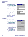
Owner
To change the Owner default settings:
1. Select Start > Settings > Control
Panel > Owner Properties. The
Input Panel opens to facilitate
entering data.
2. Enter data using the input
panel or the keypad on the
PDA.
3. To exit the Owner Properties
control panel, tap OK on the
control bar, or press <Enter> on
the keypad.
For more information on using the Network ID tab, refer to "Setting Up the
Network ID" on page 4-8.
Password
To change the Password default settings:
1. Select Start > Settings > Control
Panel > Password Properties.
2. Enter the desired password
twice as indicated in the two
fields.
3. Select to enable password protection at power-on and/or
enabling password protection
for the screen-saver.
4. To exit the Password control
panel, tap OK on the control
bar, or press <Enter> on the
keypad.
2-24
Falcon® 4400 Series with Windows® CE
PC Connection
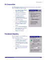
PC Connection
The PC Connection control panel determines how ActiveSync works with the
PDA. To modify the default settings:
1. Select Start > Settings > Control
Panel > PC Connection.
2. Select the first checkbox to
enable direct connections to
the desktop computer.
3. Tap Change Connection to
modify the connection method
from USB or Serial.
4. To exit the Change Connection
dialog, tap OK on the control
bar, or press <Enter> on the
keypad.
5. To exit the PC Connection Properties control panel, tap OK on
the control bar, or press
<Enter> on the keypad.
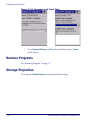
Persistent Registry
Persistent Registry saves the RAM-based
registry to persistent storage.
1. Tap Persist to persist the registry.
2. Tap Persist registry settings to
automatically persist the settings
at the time specified in the dropdown box
3. Tap Clear to delete all persistent
registry files from the Flash FX
disk.
Product Reference Guide
2-25
Configuring the Falcon
Automatically persisting the registry at frequent intervals may slow system performance.
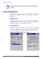
Power Configuration
To adjust power management settings, select Start > Settings > Control Panel >
Power. Use this control panel to check the charge on the battery or to change the
Power settings.
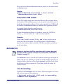
Battery Tab
The Battery tab provides power indicators for External power, Main battery, and
Backup battery as shown in Figure 2-17 on page 2-26. To save your settings, tap
OK on the command bar, or press <Enter> on the keypad.
Power Off Tab
The Power Off tab allows you to determine the idle duration and suspend mode
initiation to save battery power as shown in Figure 2-17 on page 2-26. To save
your settings, tap OK on the command bar, or press <Enter> on the keypad.
Figure 2-17. Battery and Power Tabs
2-26
Falcon® 4400 Series with Windows® CE
Regional Settings
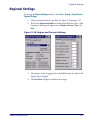
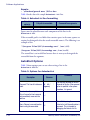
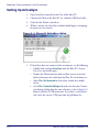
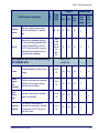
Regional Settings
To change the Regional Settings defaults, select Start > Settings > Control Panel >
Regional Settings.
1. Select your locale from the spin box. See Figure 2-18 on page 2-27.
2. Review the Appearance Samples in the bottom half of the screen. Click
Customize to change the appearance of Number, Currency, Time, and
Date.
Figure 2-18. Region and Custom Settings
3. The options on the Language tab are disabled because the Falcon will
display only in English.
4. The Input Panel will open to facilitate data input.
Product Reference Guide
2-27
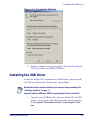
Configuring the Falcon
Figure 2-19. Language and Input Tabs
5. To exit Regional Settings, tap OK on the control bar, or press <Enter>
on the keypad.
Remove Programs
See "Removing Programs" on page 3-7.
Storage Properties
To change the Storage Properties control panel default settings:
2-28
Falcon® 4400 Series with Windows® CE
Stylus Calibration
1. Select Start > Settings > Control
Panel > Storage Properties.
2. From the Store Info pull-down
list, select the desired storage
device.
3. You can also format, dismount,
and create partitions on storage
devices using this control panel.
4. To save and exit the Storage
Properties control panel, tap OK
on the control bar, or press
<Enter> on the keypad.
Dismounting or formatting the FlashFX drive will erase all files and program stored in
the drive.
CAUTION
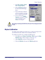
Stylus Calibration
You might need to recalibrate the touch screen (i.e. when you attempt to select
one item with the stylus, another item is erroneously selected).
To recalibrate the touch screen, complete the following steps:
1. Select Start menu > Settings > Control Panel > Stylus to open the Stylus
Properties dialog as shown in Figure 2-20 on page 2-30.
2. Adjust Double-Tap sensitivity if needed or desired.
3. Select the Calibration tab to open the Calibration application.
Product Reference Guide
2-29
Configuring the Falcon
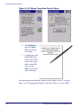
Figure 2-20. Stylus Properties Control Panel
4. Tap Recalibrate to
open the Calibration screen shown
to the right
5. Carefully press and
briefly hold stylus
on the center of the
target as the target
moves around the
screen or press
<ESC> to cancel the
stylus calibration.
For more information about the touch-sensitive display, refer to “Using the
Stylus” and “Navigating the Display” in the Quick Reference Guide (QRG).
2-30
Falcon® 4400 Series with Windows® CE
System Properties
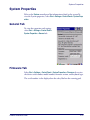
System Properties
Refer to the System control panel for information related to the system.To
view the System properties, select Start > Settings > Control Panel > System Properties.
General Tab
To view the expansion card settings,
select Start > Settings > Control Panel >
System Properties > General tab.
Firmware Tab
Select Start > Settings > Control Panel > System Properties > Firmware tab to view
the device serial number, model number, firmware version, and keyboard type.
The serial number is also displayed on the safety label on the scanning pod.
Product Reference Guide
2-31
Configuring the Falcon
Figure 2-21. Serial Number Locations
AVOID EXP
OSURE — LASER LIGHT IS EMITTED FROM THIS APERTURE
PSC
959 Terry St.
PRODUCT OF USA
Eugene, OR 97402
Complies with 21CFR and Part 15 of FCC rules.
Item # 345-4201-005 DATE OF MANUF
RADIO: BREEZECOM
EUR: CE0560
CAN: 24611032079A FCC: M52PCRNZZ-00
S
te afe
ste
d
Serial Number
BACKUP BATTERY: 3.1 V Lithium
Approved RLAN Module inside
3,186 - 4,460,120 - 4,758
NRTL
,717
- 4,59
- 5,
,2 9 7
130
387
,
4
,52
T:
A
0
P
on
cti d
du itore
Pro on
m
ty
SERIAL # FLYYDDDXXX
PRODUCT SERVICE
N263
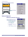
Memory Configuration
RAM Memory Allocation and Usage
Complete the following steps to adjust
the Memory Allocation (RAM Memory):
1. Select Start > Settings > Control
Panel > System Properties.
2. Select the Memory tab.
3. Move the slider to adjust memory allocation.
4. Tap OK, or <Enter> on the Falcon
2-32
Falcon® 4400 Series with Windows® CE
System Properties
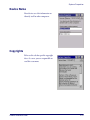
Device Name
Your device uses this information to
identify itself to other computers.
Copyrights
Refer to this tab for specific copyright
data. As a user, you are responsible to
read this statement.
Product Reference Guide
2-33
Configuring the Falcon
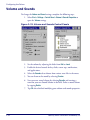
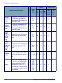
Volume and Sounds
To change the Volume and Sound settings, complete the following steps:
1. Select Start > Settings > Control Panel > Volume & Sounds Properties to
open the Volume settings.
Figure 2-22. Volume and Sounds Control Panels
2. Set the volume by adjusting the slider from Soft to Loud.
3. Enable the desired sounds for key clicks, screen taps, notifications,
and applications.
4. Select the Sounds tab to choose from various wave files in the menu.
5. You can listen to the sound by selecting Preview.
6. Save your new sound scheme by selecting Save As and entering a
name for your new Sound Scheme in the field. Delete a sound scheme
by tapping Delete.
7. Tap OK when finished modifying your volume and sounds properties.
2-34
Falcon® 4400 Series with Windows® CE
Chapter 3
Software Applications
Overview
This section contains the following topics:
Product Reference Guide
•
"Inbox" starting on page 3-2.
•
"Internet Explorer" starting on page 3-3.
•
"Media Player" on page 3-4.
•
"WordPad" starting on page 3-4.
•
"Installing Programs" starting on page 3-4.
• "Using an Installation Wizard" starting on page 3-5.
• "Installing Programs Manually" on page 3-5.
• "Using Windows Explorer to Add to the Start Menu" on
page 3-6.
• "Using ActiveSync to Add to the Start Menu" on page 3-6.
•
"Removing Programs" starting on page 3-7.
•
"Firmware Update Utility" on page 3-7.
• "Retrieving a Firmware Image Update" on page 3-8.
• "Installing FUU on the Host PC" on page 3-8.
• "Updating the Falcon Firmware" on page 3-12.
• "Restoring Falcon Firmware" on page 3-14.
•
"AutoStart" on page 3-15.
3-1
Software Applications
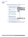
Inbox
The Falcon comes with Inbox for Windows CE installed from the factory. Inbox
is a familiar Microsoft email interface. To set up your Inbox:
1. Open Inbox by selecting Start > Programs > Inbox.
2. Select Services > Options from the
command bar to configure email.
3. Drag the screen to show Add....
Select Add....
4. Select the Service Type and type
the email service name in the Service Name text box. Select OK.
5. Enter the server and user information in the Mail Service Definition.
6. Configure your inbox using the
Mail General Preferences dialog.
7. Configure your mail retrieval settings in the Mail Inbox Preferences.
8. Tap OK to complete the Inbox configuration.
9. Select Services > Connect from the command bar.
10. Select Services > Send/Receive Mail from the command bar to manually
retrieve mail. Pending email appears in the inbox after connecting.
3-2
Falcon® 4400 Series with Windows® CE
Internet Explorer
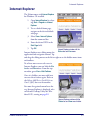
Internet Explorer
The Falcon comes with Internet Explorer
for Windows CE installed.
1. Open Internet Explorer by selecting Start > Programs > Internet
Explorer.
2. To set a default home page,
navigate to the desired default
web page.
3. Select View > Internet Options
from the command bar.
4. Enter the desired URL in the
Start Page field.
5. Tap OK.
Internet Explorer window with the
Status bar and View menu.
Internet Explorer uses sliding menus for
application and navigation control. Tap
and drag the sliding menus to the left or right to see the hidden menu items
and toolbars.
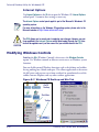
To achieve more screen real estate in
Internet Explorer, you can hide the Status bar and View menu. From the top
menubar, go to View > Hide Toolbars.
Once it is hidden, you must cold reset
to access these features again. Refer to
the Falcon 4400 Series Quick Reference
Guide (QRG) for reset instructions.
For more fine grained control over the
way Internet Explorer is displayed, refer
to Falcon® Desktop Utility for Windows® CE, starting on page B-1
Internet Explorer window with the
Status bar and View menu hidden.
Product Reference Guide
3-3
Software Applications
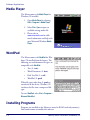
Media Player
The Falcon comes with Media Player for
Windows CE installed.
1. Open Media Player by selecting
Start > Programs > Media Player.
2. Select File > Open to open an
available existing media file.
3. Please refer to
www.microsoft.com for addi-
tional information and help with
your Microsoft Windows Media
Player.
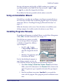
WordPad
The Falcon comes with WordPad for Windows CE installed from the factory. The
following text and document file types are
compatible with WordPad:
•
Text (*.txt)
•
Word Document (*.doc)
•
Rich Text File (*.rtf )
•
WordPad (*.pwd)
When file types other than *.pwd are
transferred to the device, Windows CE
translates the files into a compressed file
type.
To start WordPad, select Start > Programs >
Microsoft WordPad.
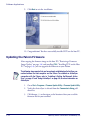
Installing Programs
Programs pre-installed on the Falcon are stored in ROM (read-only memory).
You cannot remove or modify this software.
3-4
Falcon® 4400 Series with Windows® CE
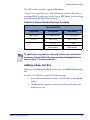
Installing Programs
You may add programs and data files to RAM (random access memory) or
into Flash memory via the FlashFX Disk. You can install *.cab, *.exe
*.zip files, or other files designed for the Falcon.
Please follow the directions provided with the software to install it.
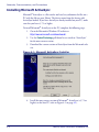
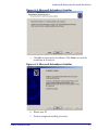
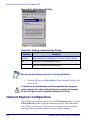
Using an Installation Wizard
If the file has an installer, the installation wizard begins automatically if you
have ActiveSync installed. Most installation programs require an ActiveSync
connection. (Refer to "Installing & Setting Up Microsoft ActiveSync" on
page 4-1.)
Follow the directions on the screen. Once the software is installed on your
desktop computer, the installer transfers the software to your Falcon.
Installing Programs Manually
To quickly install programs on multiple Falcons, use the Falcon Management
Utility (FMU). For more information, refer to page 2-12.
If the file does not contain an installer,
an error message indicates the program
is valid but is designed for a different
type of computer.
•
Install *.cab, *.exe
*.zip, setup.exe files, or
other files designed for the Falcon.
•
Windows CE applications will
also work on the Falcon.
Start by downloading the program to
your desktop computer (or insert the
CD or disk that contains the program into your desktop computer).
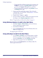
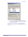
1. Select Start > Settings > Control Panel > System > General on the Falcon.
Make a note of the information in the Processor field as shown to the
right. The processor type is required to determine file type compatibility.
2. Read the installation instructions, ReadMe files, or manual that
comes with the program. Many programs provide installation instructions.
Product Reference Guide
3-5
Software Applications
•
•
If you cannot find installation instructions for the program in the
ReadMe file or manual, use ActiveSync Explore to copy the program file to the Program Files folder on your Falcon.
For more information on copying files using ActiveSync, refer to
the ActiveSync online Help.
3. Connect your Falcon and desktop computer. Refer to Networks,
Communications, and Connections, starting on page 4-1 to connect
your Falcon with your PC.
4. Double-click the *.exe or *.cab file.
5. Once the installation is complete, double-tap the program icon from
the desktop, or select Programs > program icon to select it.
Refer to "Using ActiveSync to Add to the Start Menu" on page 3-6.
Using Windows Explorer to Add to the Start Menu
1. Select Start > Programs > Windows Explorer, and select the directory
where the application or program is stored.
2. Select Cut from the Edit menu.
3. Open the Programs folder located in the Windows folder, select
Paste from the pop-up menu.
The program appears on the menu.
Using ActiveSync to Add to the Start Menu
1. Use the Explorer in ActiveSync on your desktop computer to explore
the files on your Falcon and locate the program. For more information on using ActiveSync, refer to the ActiveSync online Help.
2. Right-click on the program, then select Create Shortcut.
Move the shortcut to the Programs folder in the Windows folder. The
shortcut appears on the menu.
3-6
Falcon® 4400 Series with Windows® CE
Removing Programs
Removing Programs
Only user-installed programs can be
removed.
1. To remove a program, select Start
> Settings > Control Panel > Remove
Programs.
2. Select the program you wish to
remove from the list and tap
Remove.
Firmware Update Utility
The Falcon is equipped with a field upgradeable firmware mechanism. Firmware updates for the Falcon are uploaded to PSC‘s website (www.psc.com).
After you have downloaded the desired update, there are several ways you can
update the firmware on the Falcon.
•
Use the Falcon Management Utility (FMU) if you have multiple Falcons to update. Refer to the FMU User’s Guide on the Product CD
included with your Falcon for more information.
•
If FMU is not available or you have only a few Falcons to update, use
the Firmware Update Utility (FUU), described below, to install or
update the firmware using an ActiveSync connection. Refer to
"Installing & Setting Up Microsoft ActiveSync" on page 4-1 for more
information.
FUU can also be used to restore the firmware onto a Falcon that has become
corrupted, such as would happen if the Falcon were powered down during an
ActiveSync firmware update. See "Restoring Falcon Firmware" on page 3-14.
The following sections provide procedures for the retrieval and installation of
the most current firmware image onto a Falcon.
Product Reference Guide
3-7
Software Applications
Retrieving a Firmware Image Update
The following instructions use Internet Explorer to retrieve the most current
firmware image.
1. Launch Internet Explorer on your PC and navigate to www.psc.com.
2. Navigate to the Downloads section of the website.
3. Select the product (Falcon 44xx), desired language, and software
updates. Click Go.
4. Select the file you want to download, then click Save and navigate to
the location where you want to save the firmware files.
5. Click Save again to begin copying the files to your local machine (or
local network location).
Installing FUU on the Host PC
The Firmware Update Utility (FUU) provides administrators with a field
upgrade mechanism. You must have Microsoft® ActiveSync already loaded
and running on the host PC to use FUU. Refer to "Installing & Setting Up
Microsoft ActiveSync" on page 4-1 and "Using ActiveSync" on page 4-6 for
more information about ActiveSync.
Prior to installing FUU, you must remove any previous versions of FUU installed
on the host PC.
To install PSC’s Falcon® Firmware Update Utility, complete the following
steps on the PC:
1. Insert the CD ROM shipped with your Falcon and click on the link
to Firmware Update Utility.
OR
Go to the PSC website at www.psc.com and download the most current
version of the Firmware Update Utility. Unzip the file, then double-click
to run FUU_Setup.exe
Click OK to continue once you have removed previous versions of FUU.
2.
•
•
•
3-8
The Welcome to FUU Setup Program screen opens.
Please exit all Windows applications before running this setup.
Click Cancel to quit Setup and close any programs you have running.
Click Next to continue with the Setup program.
Falcon® 4400 Series with Windows® CE
Firmware Update Utility
3. You must agree to accept the terms of the License Agreement by clicking on the appropriate button.
4. Click Next to continue the installation.
5. The Destination Location dialog asks you to confirm the installation
location or choose a new location.
• To choose a new location, click Browse and navigate to the desired
installation location.
• Click Next to continue the installation.
Product Reference Guide
3-9
Software Applications
6. The Select Program Manager Group dialog opens.
• Click Next to accept the default Program Manager Group.
• Or select a new group and click Next.
3-10
Falcon® 4400 Series with Windows® CE
Firmware Update Utility
7. The Start Installation screen opens.
Click Next to begin the installation.
8. The Installing dialog will open and close very quickly. You may not
even see this screen.
Product Reference Guide
3-11
Software Applications
9. Click Next to exit the installation.
10. Congratulations! You have successfully installed FUU on the host PC.
Updating the Falcon Firmware
After copying the firmware image to the host PC ("Retrieving a Firmware
Image Update" on page 3-8) and installing FUU ("Installing FUU on the Host
PC" on page 3-8), you can upgrade the firmware on your Falcon.
The following steps require that you have already established an ActiveSync connection between the host computer and the Falcon. To establish an ActiveSync
connection with the Falcon, refer to "Installing & Setting Up Microsoft ActiveSync" on page 4-1 and "Using ActiveSync" on page 4-6, for more information on
ActiveSync.
1. Go to Start > Programs > Firmware Update Utility > Firmware Update Utility.
2. Verify that ActiveSync is selected from the Communicate Using pulldown list.
3. Click browse (...) and navigate to the location where you saved the
firmware file for your terminal.
3-12
Falcon® 4400 Series with Windows® CE
Firmware Update Utility
4. Select the current *.img file and click Open.
5. Verify that the Falcon is turned on. Insert the device into a powered
dock connected to the host computer.
6. Click Update Terminal on FUU on the host PC.
7. FUU will compare the selected firmware image with the firmware
already loaded on the Falcon; if the images are different, FUU will proceed to update the firmware image on your Falcon.
Product Reference Guide
3-13
Software Applications
Please be patient and do not remove the Falcon from the Dock during this procedure. The firmware image of the Falcon can take as long as:
• 12 minutes to download using a USB connection.
• 22 minutes to download using a serial connection with 115K baud rate.
• 130 minutes to download using a serial connection with 19.2K baud rate.
8. After the firmware of your Falcon has been updated, you must perform a warm reset of the Falcon. Refer to the Falcon 4400 Series Quick
Reference Guide (QRG) for reset instructions.
Restoring Falcon Firmware
If the firmware image on the Falcon becomes corrupted, the Falcon will beep
twice and show a blank screen when powered on. This can happen if a firmware update is aborted, such as during a power loss or if the Falcon is removed
from the Dock before completion of the procedure.
To reinstall the firmware, complete the following steps:
1. On the PC, click Start > Programs > Firmware Update Utility > Firmware
Update Utility.
2. Set Communicate Using to the communications port to which the dock
is attached to (ActiveSync, USB, COM1 or COM2.)
3. Click browse (...) and navigate to the file location.
3-14
Falcon® 4400 Series with Windows® CE
AutoStart
4. Select the current *.img file and click Open.
5. Verify that the Falcon is turned on. Insert the Falcon into a powered
dock connected to the host computer.
6. Click Update Terminal on FUU on the host PC.
7. FUU will restore the firmware on the Falcon as shown on page 3-12.
Please be patient and do not remove the Falcon from the Dock during this procedure. The firmware image of the Falcon can take as long as:
• 12 minutes to download using a USB connection.
• 22 minutes to download using a serial connection with 115K baud rate.
• 130 minutes to download using a serial connection with 19.2K baud rate.
8. After the firmware has been restored, the Falcon will automatically
reset.
AutoStart
The AutoStart program provides two functions:
• Automatically reinstalls specified CAB files when the Falcon starts up.
• Allows you to create a list of applications (with optional command line
arguments) to run automatically at startup.
Performing a Windows Mobile Clean Boot will remove the AutoStart folder and all
AutoStart settings. Reference the Falcon 4400 with Windows Mobile QRG for detailed
information about a Clean Boot.
CAUTION
Product Reference Guide
3-15
Software Applications
AutoStart launches each time the Falcon is rebooted with a Cold Reset.
AutoStart then installs all the CAB files located in the AutodStart CAB folder.
If the AutoStart CAB folder does not exist, no CAB files will be installed.
Table 1. AutoStart CAB folder Location
Product
Operating System
Location
\FlashFX Disk
\Windows\Autostart
Windows CE
Windows Mobile
F4400
AutoStart will then run the Autostart.ini (reference Table 2 for the location), executing each line with the specified command line arguments. It will
take into account any AutoStart options at the beginning of the line.
Table 2. Autostart.ini Location
Product
Operating System
Windows CE
Windows Mobile
F4400
Location
\FlashFX Disk
\Windows\Autostart
Installing CAB files
Copy any CAB files you want to install into the AutoStart CAB folder. These
CAB files will then be automatically installed in alphabetical order the next
time you start the device (with the exception of a Windows Mobile Clean
Boot, which would remove the CAB files). Reference the QRG for F4400 with
Windows Mobile for information about Clean Boot.
How AutoStart Uses Wceload
If you intend to create highly interactive installers, you should either install the
CABs manually or review the section on “Interactive CAB Install” in this chapter.
CAB files are installed by AutoStart using the Wceload.exe application.
Table 3 on page 3-16 shows available command line options:
Table 3. AutoStart command line options
Option
/noui
/silent
3-16
Description
Specifies that you will not be prompted for any input during the installation. If
the CAB file is signed, any responses will automatically be answered ‘Yes.’ If
the CAB is unsigned, then any responses will be answered ‘No.’
Suppresses dialog boxes during the installation.
Falcon® 4400 Series with Windows® CE
AutoStart
Please refer to the Microsoft documentation on your device for further details
on Wceload.exe.
Sample:
\Windows\Wceload.exe /delete 1 /noui /silent
“\Windows\AutoStart\<cab file>”
Interactive CAB Install
If the CAB installer requires user interaction that must be performed during
the AutoStart CAB installation process, you can specify a special file name to
disable the silent mode installation. If this mode is specified, the CAB file will
be installed with Wceload without any command line arguments specified.
An example of what AutoStart would execute is:
\Windows\Wceload.exe <cab file>
To force this mode of installation via AutoStart, rename the CAB file to
include a ‘_’ character before the “.cab” extension of the file.
Example:
“File.cab” should be renamed “File_.cab” to force AutoStart to not
install the CAB in silent mode. This specially-named CAB file should be
placed in the AutoStart folder with other CAB files intended for installation
on the next reboot.
Autostart.ini
Autoexec.ini, which uses AutoCE on some older models, has been deprecated.
These files should be renamed to Autostart.ini and reformatted as described in
"AutoStart" on page 3-15.
The Autostart.ini is a text file that AutoStart will run upon startup of the
Falcon, and after any CAB files are installed. This file should be placed in the
AutoStart folder. AutoStart will run the Autostart.ini file on each reboot
of the device (with the exception of a Clean Boot, which will remove the
AutoStart folder).
Line Formatting
Each line of the Autostart.ini can consist of Autostart options, an executable, and any command line arguments.
< Autostart option(s)> <full path to executable>
<command line arguments>
Product Reference Guide
3-17
Software Applications
Sample:
- \windows\pword.exe \file.doc
Table 4 breaks down the sample Autostart.ini line.
Table 4. Autostart.ini line formatting
Autostart
option(s)
-
Full path to executable
\windows\pword.exe
Command line arguments
\file.doc
Spaces must be placed between each component of the line in the
Autostart.ini.
If the executable path is in a folder that contains spaces in the name, quotes are
required to distinguish what the actual executable name is. The following is an
example of this:
“\Program Files\PSC\ScannerApp.exe” /run (valid)
\Program Files\PSC\ScannerApp.exe /run (invalid)
The second line is an invalid line because there is no way to distinguish the
executable from the argument.
AutoStart Options
Table 5 shows options you can use when writing a line in the
Autostart.ini file.
Table 5. Options for Autostart.ini
Comments
Description
Character
Comment: This line will not be exe- ‘#’ OR ‘ ‘
cuted.
(space)
This may only be used as the first
character of the line. If the comment
option is specified in the options
elsewhere, it is ignored.
Do not wait on line completion:
This will cause the line to execute
‘-’
and immediately move onto the
next line.
Query: Request user confirmation
‘?’
when running the executable.
3-18
This will halt parsing the
Autostart.ini until the confirmation is
answered. This is intended for
debugging the Autostart.ini file.
Falcon® 4400 Series with Windows® CE
AutoStart
Comments
Description
Character
Execute only on Cold Reset
‘!’
Cold Reset Only: This will cause the line to execute only after a Cold Reset.
An empty line will be treated as a comment line.
Combining Options
Autostart options can be combined together as shown in the following sample:
?- \Windows\Pword.exe
This line would:
• Request confirmation before executing the line. The next line would not
be processed before the confirmation is answered.
• Run the next line without waiting on the current line to complete execution.
Query Option
The query option is intended for use when debugging the autostart.ini.
When a line with this option is executed, the following dialog will appear with
the specified executable and command line arguments. The populated fields
shown in the AutoStart Execute Query are described in Table 6 on page 3-19.
AutoStart Execute Query
Table 6. AutoStart Query options
Field
Line Number
Exe
Product Reference Guide
Description
This is the line number in the script being executed.
The executable as parsed by AutoStart.
3-19
Software Applications
Field
Args
Description
The argument as parsed by AutoStart.
The fields may be broken up into multiple lines (as shown in the example) due to
limited space in the dialog.
Parentheses are used to surround the given field and make it very clear what
the value of the field is.
Table 7 describes the results of each choice:
Table 7. AutoStart Query actions
Button
Yes
No
Cancel
Action
The current line will execute.
The current line will not execute. AutoStart will continue parsing the
Autostart.ini.
The current line will not execute and AutoStart will discontinue parsing the Autostart.ini.
Autostart.ini Samples
Table 8 on page 3-20 is a collection of sample Autostart.ini lines.
Table 8. Sample Autostart.ini lines
Line
Description
? \windows\wceload.exe “\My This will confirm the execution of
Documents\FDU.cab”
\Windows\wceload.exe with specified argument
“\My Documents\FDU.cab”
\Program Files\App.exe
(invalid) This will execute \Program with the argument
Files\App.exe.
\Program Files\App.exe /run (invalid) This will execute \Program with the argument
Files\App.exe /run.
“\Program Files\App.exe” / This will execute the program \Program
run
Files\App.exe with the argument /run.
This
will confirm the execution of
?- \Windows\Pword.exe
\Windows\Pword.exe. If the execution is confirmed, AutoStart will immediately process the next line.
!”\Program Files\App.exe” / This will execute the program \Program
run
Files\App.exe with the argument /run ONLY
after a Cold Reset.
3-20
Falcon® 4400 Series with Windows® CE
Chapter 4
Networks, Communications,
and Connections
Overview
This section contains the following topics:
•
"Installing & Setting Up Microsoft ActiveSync" starting on page 4-1.
• "Installing Microsoft ActiveSync" on page 4-2.
• "Setting Up ActiveSync" on page 4-4.
•
"Installing the USB Driver" on page 4-5.
•
"Using ActiveSync" starting on page 4-6.
•
"Networking" starting on page 4-8.
• "Setting Up the Network ID" starting on page 4-8.
• "Network and Dialup Connections" starting on page 4-9.
•
"SNMP" starting on page 4-10.
Installing & Setting Up Microsoft ActiveSync
This section provides instructions on setting up the Host PC so that the PC
can communicate with the Falcon and the dock.
The screen shots in the manual were taken and the procedures were written using
Windows® XP. If you are using Windows® 2000 or Windows® NT, appearances
and procedures may be slightly different.
Important! You must disconnect any other PDAs, PDTs, or Falcons using USB
ActiveSync from the Host PC prior to connecting the Falcon or the Host PC and
Microsoft ActiveSync may not recognize the new device.
Product Reference Guide
4-1
Networks, Communications, and Connections
Installing Microsoft ActiveSync
Microsoft® ActiveSync is a file transfer tool used to synchronize the files on a
PC with the files on your Falcon. The device comes from the factory with
ActiveSync loaded. If you have ActiveSync already installed on your PC, make
sure that you have v3.7.1 or higher.
To install Microsoft® ActiveSync on the PC, complete the following steps:
1. Go to the Microsoft® Windows CE website at
http://www.microsoft.com/downloads/.
2. Use the Product/Technology pull-down list to search on “ActiveSync”
for the most current version.
3. Download the current version of ActiveSync from the Microsoft website.
Figure 4-1. Microsoft ActiveSync Installer
4. Install the most current version of Microsoft® ActiveSync (v3.7.1 or
higher) on the host PC (refer to Figure 4-1 on page 4-2).
4-2
Falcon® 4400 Series with Windows® CE
Installing & Setting Up Microsoft ActiveSync
Figure 4-2. Microsoft ActiveSync Installer
5. Click Next to continue the installation. Click Cancel to cancel the
installation of ActiveSync.
Figure 4-3. Microsoft ActiveSync Installer
6. Reboot your PC.
7. You have completed installing ActiveSync.
Product Reference Guide
4-3
Networks, Communications, and Connections
Setting Up ActiveSync
1. Open ActiveSync from the System Tray of the Host PC.
2. Connect the Falcon to the Host PC via a dock or USB/Serial cable.
3. Verify that the Falcon is turned on.
4. Within a minute, the ActiveSync window should appear, attempting
to connect to a new device.
Figure 4-4. Microsoft ActiveSync dialog
5. If ActiveSync does not connect within two minutes, try the following:
• Double-click and open ActiveSync from the Host PC’s System
Tray if it is not already open.
• Remove the Falcon from the dock and then reinsert it into the
dock or disconnect the cable from the Host PC and reconnect it.
• Select File > Get Connected for ActiveSync to look for a mobile
device.
• Go to File > Connection Settings and make sure that your Connection Settings dialog show the same selections as that in Figure 4-5
below if you have a USB connection. If you have a serial connection, select the correct COM port from the pull-down list.
4-4
Falcon® 4400 Series with Windows® CE
Installing the USB Driver
Figure 4-5. Connection Settings
6. You have completed setting up ActiveSync. Proceed to Installing the
USB Driver, below, to install the USB driver.
Installing the USB Driver
In order for the Host PC to communicate with the Falcon, you must install
the USB driver file from the CD that came with the Falcon.
Microsoft ActiveSync must be installed on your computer before proceeding. See
"Setting Up ActiveSync" on page 4-4.
Important! Install the USB driver PRIOR to connecting the Falcon to the host PC.
1. Copy the current USB driver file from your Falcon CD or the PSC
website (www.psc.com) to the following location on your computer:
C:\Program Files\Microsoft ActiveSync\Drivers.
Product Reference Guide
4-5
Networks, Communications, and Connections
2. Connect the USB or Serial cable to Falcon or place the Falcon in the
dock.
3. Connect the USB or Serial cable to a Host PC.
4. Follow the directions onscreen. The specified source directory will be
the one identified in step 1.
You are now ready to use ActiveSync.
Using ActiveSync
Use ActiveSync to transfer and synchronize (share) files between the Falcon
and the Host PC.
File Synchronizing using ActiveSync
ActiveSync file synchronization requires an ActiveSync partnership between
the Falcon and the Host PC. Refer to the ActiveSync online help for more
information.
1. Select the controls in the synchronization configuration for the Falcon
partnership. Refer to Figure 4-6 on page 4-7.
2. Select Tools > Options from the ActiveSync command bar to configure
the synchronization options.
4-6
Falcon® 4400 Series with Windows® CE
Using ActiveSync
Figure 4-6. File Synchronization Options
3. Place the file to be synchronized in the Synchronization folder
created in your My Documents directory (defaults to the desktop).
Refer to Figure 4-7 on page 4-8.
During the ActiveSync connection, all files in the Synchronization
folder will be synchronized with (copied to) the \My Documents directory
on the Falcon.
Product Reference Guide
4-7
Networks, Communications, and Connections
Figure 4-7. Select Synchronization Settings
Networking
Setting Up the Network ID
To set up your Network ID (configure the Windows user settings, such as the
user name, password, and domain), complete the following steps on the Falcon:
1. Go to Start > Settings > Control Panel > Owner.
2. Select the Network ID tab on the Owner Properties dialog box.
3. Enter your User Name, Password, and Domain on the Network ID tab.
4. Select OK on the command bar to save your network ID information.
Access basic network connection information by double-tapping on the Network icon in the system tray. Tap Details to show more information.
The Network Icon
The network icon in the system tray indicates if the network is currently connected or not.
4-8
Falcon® 4400 Series with Windows® CE
Networking
Figure 4-8. The Network Icon
Connected
Not Connected
Network
Connection Icon
11:57 AM
System Tray
Network and Dialup Connections
RF Configuration Parameters
This utility allows setting different profile
combinations for a Cisco RF card, and
designating the current profile.The ACU
also provides firmware updates, site surveys, status and statistics data screens. For
further information, see the help file
located on your Falcon at:
Windows\Cisco Setup.htm.
To set the RF configuration parameters for
the Cisco 802.11b radio, complete the following steps:
1. To open the Cisco Aironet Client
Utility (ACU), go to Start > Settings
Control Panel > Cisco Aironet.
2. Tap Edit to edit the Active Profile’s Properties.
Product Reference Guide
4-9
Networks, Communications, and Connections
3. Select the desired Property from
the menu list.
4. Input the appropriate Value.
5. Tap OK.
6. Select OK on the menu bar to
close the control panel.
For additional assistance in using ACU to
configure your RF network, tap the question mark to access online help or contact
Cisco directly at http://www.cisco.com/.
Windows Zero Config should be used to administer the radio for cards not
specifically listed (for example, DRCB or Broadcom based radio). Refer to the
manufacturer of your radio card for further information.
SNMP
SNMP (Simple Network Management Protocol) is the standard protocol for
managing devices on a network. The Falcon Management Utility (FMU)
makes use of SNMP to send and receive configuration information to the PSC
terminals. Since the networked terminals are constantly running SNMP, this
allows FMU to interface with the terminal at any time, without requiring user
intervention on the terminal.
With SNMP running on the terminal, other SNMP based network management tools such as HP Openview® and CastleRock SNMPpc® may also be
used to interface with the terminals. To support this capability, PSC has
released the Management Information Base (MIB) for the PSC Windowsbased terminals. The MIB is used by the management tools to allow them to
better support the configuration values provided on the terminals, such as
scanner controls and terminal type information.
The MIB is available at www.psc.com.
For more information on SNMP, refer to SNMP Interface, or go to:
www.microsoft.com.
4-10
Falcon® 4400 Series with Windows® CE
Appendix A
Accessories
Overview
This appendix covers the following topics:
•
"Power Supplies" on page A-2.
• "Battery Pack" on page A-2.
• "Single-Slot Dock" on page A-2.
• "Four-Slot Dock" on page A-3.
• "Battery Charger" on page A-3.
• "Serial Charging Cable" on page A-4.
• "USB Cable" on page A-4.
• "Printer Cable" on page A-4.
• "Serial Printer Adapter" on page A-4
•
"Holsters and Softcases" starting on page A-6.
• "Holsters" starting on page A-6.
• "Softcases" starting on page A-7.
•
"Installing the Handle or Handstrap" starting on page A-8.
• "Installing a Handle on the Falcon 4410" on page A-9.
• "Installing the Handstrap on the Falcon 4420" on page A-8.
•
"Tethered Stylus" on page A-10.
Contact your PSC reseller for accessories and supplies for the Falcon; you can
see the options in this appendix or in the PSC price book at www.psc.com.
Product Reference Guide
A-1
Accessories
Power Supplies
Use only the correct battery chargers and docks with this Windows CE color Falcon. This technology used for these models is incompatible with other PSC Falcon chargers and docks.
Battery Pack
Figure A-1. 4-Battery Pack
Single-Slot Dock
Figure A-2. Single Slot Dock
Battery Pack in
Spare Battery
Charging Slot
Power LED
A-2
USB/Serial Connector
Spare Battery
LED
Falcon® 4400 Series with Windows®CE
Power Supplies
Four-Slot Dock
Figure A-3. Four-Slot Dock
Battery Charger
Figure A-4. LiIon Battery Charger
Four-Slot Battery Charger
Product Reference Guide
A-3
Accessories
USB Cable
See Figure E-1 on page E-1.
Serial Charging Cable
See Figure E-2 on page E-2.
Printer Cable
See Figure E-3 on page E-2.
Serial Printer Adapter
The Serial Printer Adapter attaches to the bottom of a Falcon unit and allows
you to print directly to a printer.
Figure A-5. Serial Printer Adapter
To attach the printer adapter to a Falcon, you must remove the strap studs, as
well as the optional strap stud bumpers, if present. Use the procedure that follows.
A-4
Falcon® 4400 Series with Windows®CE
Power Supplies
Removing Strap Studs/Bumpers
Figure A-6. Strap Studs
Strap Stud
Bumpers
Strap Studs
1. Loosen and pull off the strap stud bumpers (if present). If necessary,
pry off using a screwdriver.
2. Use a 5/64” Allen wrench (included with the printer adapter) to
loosen and remove each Strap Stud.
Once you have removed the strap studs, attach the adapter to the Falcon by
tightening the thumbscrews on the adapter.
Figure A-7. Attaching the Serial Printer Adapter
Product Reference Guide
A-5
Accessories
Holsters and Softcases
A holster and a softcase are available that will work with both the Falcon 4410
and the handled Falcon 4420 models.
Holsters
Figure A-8. Three Holster Views
A-6
•
Quick release swivel belt
mount (clip on both sides for
left or right mount)
•
Heavy duty nylon
Falcon® 4400 Series with Windows®CE
Holsters and Softcases
Softcases
Figure A-9. Softcase for Handled Falcon 4420
Product Reference Guide
•
Belt clip option
•
Stylus holder
•
Open cover
•
Heavy duty nylon
•
Scanner window
A-7
Accessories
Installing the Handle or Handstrap
The Falcon 4420 comes from the factory with the handle installed. The Falcon
4410 comes with a handstrap. These can be exchanged with a change-out kit.
The handle is removable and can be replaced with a handstrap. When you
replace the handle with the handstrap, you lose the ability to press the trigger
on the handle and must use the <Scan> key on the Falcon keypad instead.
To remove the handle and replace it with the handstrap refer to the following
sections. Reverse the same directions to replace the handstrap with the handle.
Installing the Handstrap on the Falcon 4420
To install a handstrap on the Falcon 4420, complete the following steps:
1. Remove the handle as shown in Figure A-11 by removing the screws
located just above the battery cover’s latch dials.
2. Insert the top tab of the handstrap cover into the slot at the top of the
handle recess. (refer to Figure A-10)
Figure A-10. Removing/Replacing a Handstrap
Cover
Plate
Retaining
Pin
Handstrap
Cover
Plate
Handstrap
PDT
Retaining Pin
is threaded
through loop
in strap and
seated in sockets
3. Replace the screws located just above the battery cover’s latch dials.
A-8
Falcon® 4400 Series with Windows®CE
Installing the Handle or Handstrap
4. Connect the handstrap hook onto one of the strap studs at the base of
the Falcon.
5. The process is complete upon successful test of the scanning function.
Installing a Handle on the Falcon 4410
To install the handle on the Falcon 4410, complete the following steps:
1. Remove the handstrap as shown in Figure A-10 by removing the
screws located just above the battery cover’s latch dials.
Figure A-11. Removing/Replacing the Handle
Handle
PDT
2. Insert the top tab of the handle into the slot at the top of the handle
recess (refer to Figure A-11).
Product Reference Guide
A-9
Accessories
3. Replace the screws located just above the battery cover’s latch dials.
4. The process is complete upon successful test of the trigger function.
Tethered Stylus
An optional Tethered Stylus is available
for use on any of the Falcon 4400
series models. The Tether attaches the
stylus to the Falcon unit, preventing
the stylus from accidentally becoming
lost or misplaced.
Tether
Installing a Tethered Stylus
If your Falcon did not come with a Tethered Stylus, it can be easily installed.
To install a Tethered Stylus on the Falcon 44xx complete the following steps:
1. Turn the Falcon face-down. Ensure that power is OFF.
2. Using a Phillips screwdriver, remove the 6 mm screw at the bottom of
the Stylus holder.
3. Use the longer 16 mm screw included with the Tethered Stylus kit to
attach the Tethered Stylus to the Falcon.
CAUTION
Do not use the 16mm long screw that came with the Tethered Stylus without the
Tether. Damage to internal components could occur if the screw is used without
the Tether, since the screw is longer than the standard 6 mm screw used without
the Tether.
4. Slide the other end of the Tether through the Stylus.
This completes Installation of the Tethered Stylus.
A-10
Falcon® 4400 Series with Windows®CE
Tethered Stylus
Figure A-12. Installing/Removing a Tethered Stylus
Tether
Screw
Removing a Tethered Stylus
If you want to remove the Tether from your Falcon 44xx, complete the following steps:
1. Turn the Falcon face down. Ensure that power is OFF.
2. Using a Phillips screwdriver, remove the 16 mm screw at the bottom
of the Stylus holder that attaches the Tether to the PDT.
3. Use the shorter 6 mm screw included with your Falcon to reattach the
Stylus Holder to the Falcon.
CAUTION
Do not use the 16 mm long screw that came with the Tethered Stylus without the
Tether. Damage to internal components could occur if the screw is used without
the Tether, since the screw is longer than the standard 6 mm screw used without
the Tether.
Removal of the Tethered Stylus is complete.
Product Reference Guide
A-11
Accessories
NOTES
A-12
Falcon® 4400 Series with Windows®CE
Appendix B
Falcon® Desktop Utility for
Windows® CE
Overview
Falcon® Desktop Utility (FDU) allows PSC Falcon® Windows® administrators to configure Falcon Windows®CE Falcons to control individual user
access. This includes:
•
Prevent users from changing Falcon OS settings.
•
Define keys to access specific functionality/programs.
•
Use Application Selector to replace desktop with a selection of authorized applications.
•
Internet Explorer access restriction, configuration and customized
recovery mechanisms.
This section covers the following information:
•
Product Reference Guide
"Falcon Desktop Utility" on page B-2
• "Administrative Options" on page B-3.
• "Setting Hot Keys" on page B-5.
• "Internet Explorer Configuration" on page B-8.
• "Modifying Windows Controls" on page B-10
• "Add Application" on page B-12.
B-1
Falcon® Desktop Utility for Windows® CE
Falcon Desktop Utility
To open the FDU for the first time, select Start > Settings > Falcon Config.
Figure B-1. Accessing FDU
These options are available from all screens:
Table B-1. Options Available on all Screens
Command
B-2
Description
OK
Tap OK to apply the settings and modifications you have made in the FDU
tabs. OK saves every modification.
X
Tap X to cancel the settings and modifications you have made in the FDU
tabs. X cancels all modifications you have made in FDU.
Falcon® 4400 Series with Windows®CE
Falcon Desktop Utility
Administrative Options
When you open the Falcon Admin control panel, the FMU tab will open. Select
the Admin tab to set up FDU.
Figure B-2. Setting a Password/Admin Tab Fields
Table B-2. Setting a Password/ Admin Tab Fields
Command
Enable Falcon
Desktop
Description
Select/tap this checkbox to activate the FDU functions such as Hot Key
assignments, IE Restrictions, Windows Settings, and the authorized
application menu.
Enter Password Enter a password in the text box. This allows the user to specify a password when this utility is launched. By default there is no password. A
password can consist of all standard keyboard characters.
Re-Enter
Password
Set Password
Carefully re-enter the password in the second text box.
Select/tap Set Password to enable the password.
To change or remove the password, enter a new value, re-enter the new
value, and select/tap Set Password.
Restore Defaults Select/tap Restore Defaults to reset the default values of all the functions on all the tabs. After you select this option, you will receive a
prompt to verify this selection.
Product Reference Guide
B-3
Falcon® Desktop Utility for Windows® CE
Setting a Password
To set a password:
1. Enter a password in the field. This allows the user to specify a password when this utility is launched. By default there is no password set.
Be sure to record the Password for future reference.
2. Re-enter the password in the second field.
3. Select/tap Set Password to enable the password.
4. Select/tap OK close the Set Password Confirmation dialog.
You must select/tap Set Password prior to exiting FDU in order to store and activate your new password. It is not necessary to select Enable Falcon Desktop.
If you select/tap Restore Defaults it will remove all custom settings and restore all
the factory default settings, except a previously set password.
CAUTION
Changing a Password
To change to a new password:
1. Enter a new value in the Enter Password field.
2. Re-enter the new value in the Re-enter Password field.
3. Select/tap Set Password.
Removing a Password
To remove a password:
1. Enter blanks in both Password fields.
2. Select/tap Set Password.
Password Request Dialog Box
Once the password is set, the next time you open the Falcon Desktop Utility, the
FDU Password dialog box opens.
B-4
Falcon® 4400 Series with Windows®CE
Falcon Desktop Utility
This dialog box will only open if a password was defined.
Figure B-3. Setting a Password
Table B-3. Setting a Password Dialog
Command
Description
Enter Password
Enter your password using the keypad, or using the stylus on the soft
input panel (SIP) in the text box.
OK
Select/tap OK to accept the password.
X
Select/tap X to cancel the request to start the FDU.
Complete the FDU Config dialog:
1. Type in your password using either the keypad on the unit, or using
the stylus on the soft input panel (SIP).
If you enter an incorrect password, the system will prompt you to
input the correct one.
2. Select/tap OK to verify the password. Or tap X to cancel.
Setting Hot Keys
You can use Hot Keys (HKeys) Tab to associate specific keys, such as <F1><F10>, with specific applications. You can also create a new Hot Key combinations ("Adding a New Hot Key" on page B-7). Select the HKeys tab to access these
options.
For example, you could set <F2> to launch a sample application like:
\Windows\pword.exe.
Product Reference Guide
B-5
Falcon® Desktop Utility for Windows® CE
Figure B-4. Hot Keys Tab
Table B-4. Hot Keys Tab Fields
Command
B-6
Description
Hot Key
This pull-down list displays the available function keys to define. Select the
desired one from the list.
New
Select/tap to specify a new Hot Key, not on the Hot Key list. This opens a
new dialog, shown on page B-7.
Delete
Tap to delete the selected Hot Key. You can only delete the Hot Keys you
have added. You cannot delete <F1> -<F10>.
This pull-down list displays the available functions. Select either Appli-
Associated
Function
cation or Action.
Application
Displays path to the selected application.
Browse
Select/tap
to browse for application files. You can associate an executable program with the specified Hot Key.
Arguments
Type the command-line arguments that are needed for the specified application. This option is only available when Application is selected in
the Associated Function pull-down list.
Action
Specify an action to associate with a Hot Key. This list includes: SIP,
toggle Taskbar, FDU Admin, and Application
Switcher. This option is only available when Action is selected in
the Associated Function pull-down list.
Falcon® 4400 Series with Windows®CE
Falcon Desktop Utility
The <F6> is the key initially assigned to FDU Admin:
If you wish to assign this key to a different function, you must first select an
unassigned Hot Key and assign it to the Action - FDU Admin. You can then go
back and reassign the FKey to something else.
Table B-5. Falcon Models/Hot Keys Available
Falcon 4400 Series
26-key models
48-key models
52-key models
Alpha-numeric
Alt + Alpha-numeric
Alt + Alpha-numeric
F1-F19
Alt + F1-F10
Alt + F1-F20
F1-F10
F1-F20
Alpha-numeric
Alpha-numeric
The administrator is responsible for verifying that these keys don’t override existing functions. To prevent FDU Hot Keys from overriding existing application keys,
select “No Action” in the Action combo box.
Adding a New Hot Key
When you select New on the HKeys tab, this opens the Add New Hot Key dialog
box.
To define a new Hot Key, complete the following steps:
1. Enter the key combination to define a new Hot Key in the Enter Key
textbox.
2. The Note displays important information indicating Hot Keys that
should not be used.
Product Reference Guide
B-7
Falcon® Desktop Utility for Windows® CE
Figure B-5. Add a New Hot Key
Table B-6. Adding a New Hot Key Dialog
Command
Description
Enter Key
Enter the desired key combination in this text box to define a Hot Key.
OK
Select/tap OK to add the specified Hot Key.
X
Select/tap X to cancel the specified Hot Key.
Make sure you do not attempt to add a Hot Key that is already defined.
3. Select/tap OK to save the New Hot Key. If you select/tap X, the key will
not be saved.
It is possible for the keyboard wedge to activate assigned Hot Keys using alphanumeric characters. Bar codes containing characters associated with assigned
Hot Keys will trigger the action or application assigned to that Hot Key.
Internet Explorer Configuration
Tap the IE (Internet Explorer) tab to access the IE Configuration option. Use the
IE Error Redirection option to provide customized recovery from common IE
errors. When an error occurs, the browser can redirect access to a specified
error page with instructions on how to recover from the problem.
B-8
Falcon® 4400 Series with Windows®CE
Falcon Desktop Utility
Figure B-6. IE Configuration Tab / IE Window Features
IE Address Bar
IE Tool Bar
IE Menu Bar
IE Status Bar
Table B-7. IE Tab Fields
Command
Error Type
Description
The Error Types pull-down list displays available IE Error Types:
(400) Invalid Syntax, (403) Request Forbidden, (404) Object Not
Found, (406) No Response Format, (410) Page Doesn't Exist, (500)
Internal Server Error, (501) Server Can't Do That, Generic Error,
Server Is Busy, Couldn't Find Server, URL Syntax Error, Request
Cancelled, Not Available Offline
Error Page
Edit this textbox to associate a website or html file with the specified
error.
Assign as Default
Select/tap to set a specified error page as the default. A confirmation
dialog opens to ask if the default error page applies to all errors.
Browse
Select/tap to browse for files.
Show Address Bar Select/tap this check box to show the IE address bar.
Show Tool Bar
Select/tap this check box to show the IE toolbar.
Show Status Bar
Select/tap this check box to show the IE status bar.
Show Menu Bar
Select/tap this check box to show the IE menu bar.
Product Reference Guide
B-9
Falcon® Desktop Utility for Windows® CE
Internet Options
Tap Internet Options on the IE tab to open the Windows CE Internet Options
control panel. Customize these settings as necessary.
The Internet Options control panel applet is part of the Microsoft® Windows® CE
operating system.
For more information on the Windows CE operating system, please refer to the
Microsoft website at http://www.microsoft.com.
The FDU allows you to cancel prior to applying your changes. However, any settings modified in the Internet Options control panel applet through the FDU interface will be applied even if you later cancel the your modifications in the FDU.
CAUTION
Modifying Windows Controls
Select/tap the Win (Windows Controls) tab to access the Windows Controls
option. Use Windows controls to allow or restrict access to Windows system
functions.
You can disable normal Windows functions such as the desktop and taskbar,
leaving nothing but a blank workspace. This allows applications to be run on
the full screen and prevents users from accidental or unauthorized use of the
taskbar, Internet Explorer, and any other resident applications.
Figure B-7. Windows CE Desktop and Win Tab
WinCE
Desktop
Start Menu
Taskbar
B-10
Falcon® 4400 Series with Windows®CE
Application Selector
Table B-8. Win Tab Fields
Command
Description
Show Taskbar
Select/tap Show Taskbar to specify that the taskbar is shown or
hidden.
Taskbar Enabled
Select/tap Taskbar Enabled to specify whether the taskbar is
accessible. This option is only available when the Show Taskbar
is checked.
Start Menu Enabled
Select/tap Start Menu Enabled to specify whether the Start menu
is accessible or not. This option is only available when both Show
Taskbar and Task Bar Enabled are checked.
Windows CE Desktop Select/tap Windows CE Desktop Enabled to specify that the
Enabled
desktop icons are accessible or not.
Application Selector
Use the Application Selector (AppSelect Tab) function to edit, add, or delete
applications for the application selector.
Figure B-8. AppSelect Tab
Product Reference Guide
B-11
Falcon® Desktop Utility for Windows® CE
Table B-9. AppSelect Tab Fields
Command
Description
Enable Application Select/tap Enable Application Selector to enable/disabled the
application selector. When this is enabled, the Application Selector
Selector
replaces the desktop and allows only authorized use of applications.
Authorized
Applications
This is a list of applications that the user may access.
New
Select/tap New to create a new application entry.
Edit
Select/tap Edit to edit the selected entry.
Delete
Select/tap Delete to delete the selected entry.
Up/Down
Select/tap Up/Down to move an entry up or down in the listview.
Add Application
The Add Application dialog opens when you tap either New or Edit.
From the Add Application dialog the administrator can configure and/or add/
change an a new application entry in the list.
Applications with the Run Application at Startup option enabled will start automatically when the Application Selector starts up.
Figure B-9. Add Application Dialog
B-12
Falcon® 4400 Series with Windows®CE
Application Selector
Table B-10. Add Application Dialog
Command
Description
Application Title
Type the name of the application in this textbox in the way you wish it to
appear for the user.
Executable
Displays the path for the executable file which you want to run.
Browse
Select/tap
to browse for the desired executable file. The results of
this search are placed in the Executable textbox.
Arguments
Type any command line arguments to be used when an application is
executed.
Icon File
Displays the path/link to the desired icon file.
Browse
Select/tap
to browse for the desired icon file. The results of this
search are placed in the Icon File textbox.
Run Application at Select/tap this box to force this application to auto start when the Application Selector starts up. Applications will be started in the order listed
Startup
in the authorized application list.
Delay
Enter a delay duration in seconds in the combo box.
This option delays auto start of application(s) to allow drivers to load
prior to starting applications
OK
Select/tap OK to add/save changes.
X
Select/tap X to cancel the creation of this entry.
Product Reference Guide
B-13
Falcon® Desktop Utility for Windows® CE
Application Selector
The administrator can choose for the user to have access to the desktop or not.
The Application Selector can replace the desktop and limit the user to the
specified list of applications.
Figure B-10. Application Selector
The user can select/tap the desired application.
The administrator can customize this list as shown in "Application Selector"
on page B-11.
B-14
Falcon® 4400 Series with Windows®CE
Application Switcher User Interface
Application Switcher User Interface
The application switcher provides the same functionality as the standard Windows® Alt+Tab function. This allows the user to cycle through the various
open applications.
The <Esc> key can be used to close the Application Switcher.
The application switcher is activated via an
assigned Action key specified in the Hot Key tab.
(Refer to "Setting Hot Keys" on page B-5.)
When the assigned Hot Key is pressed, the dialog shown to the right will be displayed.
The application switcher can only be assigned
to a single Hot Key, not a Hot Key with modifier
keys. For instance, <Shift>+<F3> cannot be
assigned to the task switcher action, but <F3>
can be.
Press the Hot Key assigned to open the application switcher. Press the assigned Hot Key to
cycle through the running applications when
the dialog is open. Press <Enter> to switch to the selected application or <Esc>
to close the application switcher.
Product Reference Guide
B-15
Falcon® Desktop Utility for Windows® CE
NOTES
B-16
Falcon® 4400 Series with Windows®CE
Appendix C
Configuring the Web Server
Overview
The Web Server can perform several different actions, including generating a
web page containing statistics relating to performance of the mobile computer.
The Web Server can also be used for creating an interface for interaction with
the Terminal to configure system behavior.
This section contains the following topics on configuring the Web Server:
•
Enabling the Web Server below.
•
"Testing the Web Server" on page C-3.
•
"Launching the Network Administration Page" on page C-4.
•
"Web Server Registry Settings" on page C-4.
•
"Creating and Using an ISAPI Service" on page C-6.
Enabling the Web Server
By default the Web Server is disabled. The following demonstrates how to
enable the Web Server:
1. On the Falcon 44xx, either through a CE-based registry editor or
using the Remote Tools RemoteRegEdit included with eVC++ 4.0,
modify the following registry entry:
[HKEY_LOCAL_MACHINE\COMM\HTTPD]
"Enabled"=dword:1
2. In a Command Prompt window on the Terminal, type the following:
\> services list
This will display a list of loaded and services and their state.
3. If the service HTP0: is not listed, then type the following to load the
HTTP Web Server:
\> services load httpd
Product Reference Guide
C-1
Configuring the Web Server
4. If the service is listed and not running, type the following to start the
HTTP Web Server:
\> services start HTP0:
5. To restart the Web Server, type:
\> services refresh HTP0:
This will cause the Web Server to reload any information pertaining to the
Web Server in the registry. For additional information on the registry entries,
see "Web Server Registry Settings" on page C-4.
To configure the Web Server to allow access to the Web and Net administration pages:
1. On the Falcon 44xx create the following registry entries:
[HKEY_LOCAL_MACHINE\COMM\HTTPD\VROOTS\/NetAdmin]
“Default” = “\windows\natadmin.dll”
[HKEY_LOCAL_MACHINE\COMM\HTTPD\VROOTS\/WebAdmin]
“Default” = “\windows\httpdadm.dll”
2. In a Command Prompt window on the Terminal, type the following:
\> services refresh HTP0:
Setting Up a User
The following example demonstrates how to set up a user named Testuser
in a group called Testgroup.
To configure User and Group Permissions for the Web Server:
1. On the Falcon 44xx, launch Internet Explorer and type the following
address in the address bar: http://localhost/NetAdmin. The Web-based
network configuration utility appears.
2. Fill in the Enter new password and Confirm new password boxes, then
click Submit on the bottom of the page.
3. On the menu bar of the displayed web page, click the User Accounts
link. The Enter Network Password dialog box appears.
4. Type Admin in the User Name box, and type the password that you
specified above in the Password box. Leave the Domain box empty.
5. Click OK. The User Manager Setup page appears.
C-2
Falcon® 4400 Series with Windows®CE
Testing the Web Server
6. In the Logon Name dialog, type Testuser in the Create a new user
box, then click Create.The User Manager Setup page appears.
7. On the User Configuration page, type a password for Testuser, confirm the password, and then click Create Account. The new user will
appear below the Logon Name box on the User Manager Setup page.
8. In the User Group Setup box, type Testgroup in the Create a new
group box. Click Create.
9. Click Return to user configuration page to return to the User Manager
Setup page. The new group will appear below the Group Name box on
the User Manager Setup page.
10. Click Modify beside the Group Name box containing Testgroup.
The Group Configuration page appears.
11. Select the check box in the Member of group? column for Testuser,
and then click Submit Changes.
You have now added Testuser to the Testgroup group.
You can also create users programmatically by calling the NTLMSetUserInfo function.
Windows CE also exposes the NTLMDeleteUser function, which is used to delete a
user from the local database, and the NTLMEnumUser function, which is used to
enumerate users in the local database.
Testing the Web Server
After you have created your user accounts and groups for the Web Server, you
can test the Web Server by launching the Web Server configuration page from
a host PC. This will demonstrate that your user has been granted administrative rights for the Web Server and therefore can access any virtual directory on
the Web Server.
To launch the Web Server configuration page from your host PC:
1. On the Falcon 44xx, verify that the Connected Network icon appears on
the taskbar. This icon indicates you are connected to the network.
2. Double-click the Network icon, and then select the IP Information tab to
obtain the Falcon’s IP address.
3. On the PC, launch Internet Explorer and type the following information in the address bar: http://<IP address from Falcon 44XX>/
Webadmin.
Product Reference Guide
C-3
Configuring the Web Server
4. The Web Server Login dialog appears. Type Admin in the User Name
box and enter the password you specified. Click OK, and the Web
Server Configuration page will appear.
5. Scroll to the bottom of the page, and click Modify to the right of the
Default Website box. The Default Website page appears.
6. Click the link to Configure the Virtual Directories. The Virtual Directory
Configuration page appears.
7. Verify that the following virtual directories are listed on the page:
/WebAdmin/
/NetAdmin/
8. Click Return to the Default Website configuration page. The Default Website page appears.
9. Click Configure the Administrative Users for this Website. The Administrative Users page appears.
10. Select Enabled for Testuser, and then click Update. A message telling you that your modifications have been saved and asking you to
restart the Web Server appears at the top of the page.
11. To restart the Web Server, select Restart Web Server from the menu bar.
Launching the Network Administration Page
To launch the network administration page from your host PC:
1. Open Internet Explorer and type the following information in the
address bar: http://<IP address from Falcon 44XX>/NetAdmin. A
dialog box asking for the user name and password appears.
2. Type Testuser in the User name box and the password you created
for this user in the Password box, and then click OK. The Network
Administration page appears.
Web Server Registry Settings
To gain access to a virtual path, a user must be authenticated using NTLM
authentication or Basic authentication. Specify the authentication level by setting the “a” value for each virtual path.
C-4
Falcon® 4400 Series with Windows®CE
Web Server Registry Settings
For more information on the registry settings and what each key represents,
see the Windows® CE SDK help documentation included with embedded
Visual C++ 4.0 SP2. The help file contains a wealth of information on this
topic.
Adding these values will create virtual root directories for the Basic and
NTLM-based authentication methods.
[HKEY_LOCAL_MACHINE\COMM\HTTPD\VROOTS\/WebAdmin]
@="\\windows\\httpdadm.dll"
"a"=dword:0
[HKEY_LOCAL_MACHINE\COMM\HTTPD\VROOTS\/BasicOnly]
@="\\"
"a"=dword:1
"Basic"=dword:1
"NTLM"=dword:0
[HKEY_LOCAL_MACHINE\COMM\HTTPD\VROOTS\/NTLMOnly]
@="\\"
"a"=dword:1
"Basic"=dword:0
"NTLM"=dword:1
[HKEY_LOCAL_MACHINE\COMM\HTTPD\VROOTS\/BothAuth]
@="\\"
"a"=dword:1
"Basic"=dword:1
"NTLM"=dword:1
Setting the "a" value to zero (0) enables anonymous users to have access to all
files in the virtual directory. This potentially opens the device up to hackers. Setting this value to zero (0) is permissible for internal development and testing purposes. However, you should never ship a Web Server device with the "a" value set
CAUTION to zero (0) for any configuration page.
To set the password for the entire Web Server device for Basic authentication, you
can create a configuration application that runs on the device and calls the SetPassword function. Setting the password programmatically through SetPassword
is the equivalent of the device password setting that you add in Control Panel.
Product Reference Guide
C-5
Configuring the Web Server
Creating and Using an ISAPI Service
Developers can create an ISAPI service written in eVC++ to access the APIs
available on the Terminal. The two sample .dlls below demonstrate setting and
getting a few of the configurable items available in the Falcon 44xx SDK.
Setting Configuration Items
The following example shows how to set the Code 39 minimum label length
to 10 characters:
1. Create a virtual directory under the root called SetSym and set the
Default registry entry to SetSym.dll while making sure the full
path is included.
[HKEY_LOCAL_MACHINE\COMM\HTTPD\VROOTS\/SetSym]
@="\\windows\\SetSym.dll"
2. Restart the Web Server as described on page C-2.
3. Enter the following information into Internet Explorer on the Terminal or host PC:
http://<ip address of Terminal>/SetSym?CD39MIN&10
Getting Configuration Items
The following example demonstrates how to get all the settings for Code 39:
1. Create a virtual directory under the root called GetSym and set the
Default registry entry to GetSym.dll while making sure the full path is
included.
[HKEY_LOCAL_MACHINE\COMM\HTTPD\VROOTS\/GetSym]
@="\\windows\\GetSym.dll"
2. Restart the Web Server as described in the first section. (C-2)
3. Enter the following information into the Internet Explorer on the
Terminal or desktop computer:
http://<ip address of Terminal>/GetSym?C39
These two samples are only the beginning of what can be accomplished with
the Web Server. Please note that ISAPI is currently the only method of serverside method invocation. Please consult the Help file associated with the SDK
and eVC++ for more information on ISAPI and Web Server features.
C-6
Falcon® 4400 Series with Windows®CE
Appendix D
SNMP Interface
Overview
SNMP Concepts
Simple Network Management Protocol (SNMP) is a standardized protocol for
network management services using a client/server model. The network management program (client) issues queries and commands to the remote device
(agent/server). The protocol itself defines a number of variable types and structures, and the rules for using them for data transfer. Using these variable types
and rules, there are a number of standard variables that are supported by all
SNMP agents. These standards include network addressing (IP address, subnet mask, etc.), and network statistics (total packets, bad packets, etc.).
FMU uses Simple Network Management Protocol (SNMP) to perform many
of its functions. When the Terminal Configuration or Terminal Report function is selected, SNMP is used to query the Terminal for its current Configuration settings, as well as current status information such as battery status and
memory usage. In the same function, SNMP is used to update Terminal Configuration settings when directed to. SNMP is also used by the FMU Servers
to perform the automated Group Configuration update. The Server issues
SNMP queries to discover the current Terminal Configuration, then uses
SNMP commands to update any Configuration settings that need it.
MIB Files
A Management Information Base (MIB) is a file that defines a set of SNMP
variables, their types and usage. There are a number of standard MIBs available, depending on the information being managed.
Product Reference Guide
D-1
SNMP Interface
PSC MIBs
Beyond the standard values, SNMP allows manufacturers to define their own
private MIBs. For example, PSC has been assigned an MIB by the Internet
Assigned Numbers Authority that allows PSC to define SNMP values relating
specifically to devices that we manufacture. Within the PSC MIB, several categories of values have been defined including scanner Configurations, Terminal
power Configurations and Terminal network parameters.
The format of an MIB follows rules laid out in the appropriate standards,
allowing the manufacturers of network management tools such as HP OpenView and CastleRock SNMPc to make use of the MIBs developed by manufacturers. So by following the procedures used by the management tool, the
MIB can be processed by the tool allowing the proper display of SNMP values
retrieved from the agent.
For example, if the PSC MIB is loaded into OpenView, the administrator can
then view all of the values defined by PSC using the names assigned by PSC,
as well as a brief explanation of what each value represents. This will also allow
the administrator to update most values, and provides range checking information for the tool to take advantage of. The current PSC MIB can be found
on the PSC website at www.psc.com in the Downloads area.
Additional Resources
Additional information on SNMP can be found at the following websites:
www.snmplink.org
www.snmpworld.com
www.simpleweb.com
D-2
Falcon® 4400 Series with Windows®CE
Appendix E
Cable & Connector Configurations
Introduction
The following pages contain information about standard interface cables for
use in interconnecting the Dock to power and/or peripheral devices.
General Specifications
Wire Requirements
•
Cable length should not exceed 15 feet.
•
Wire gauge = Standard for RJ-45 connectors (28-26 AWG).
Supply Voltage
Current power supply voltage = 12V, 2.5 amp.
USB Cable
Figure E-1 illustrates the connector configuration of the USB cable for the Falcon.
Figure E-1. USB Connector Configurations
4
3
1
5
PC END
FALCON END
72.0" ±2.0"
Product Reference Guide
E-1
Cable & Connector Configurations
Serial Cable
Figure E-2 illustrates the connector configuration of the Serial cable for the
Falcon.
Figure E-2. Serial Connector Configurations
HRS
72 inches +/- 2
Falcon End
PC End
Printer Cable
Figure E-3 illustrates the connector configuration of the Printer cable for the
Falcon.
Figure E-3. Printer Connector Configurations
HRS
6 inches +/- 1
Printer Cable End
E-2
Falcon End
Falcon® 4400 Series with Windows®CE
Appendix F
Programming Parameters
Overview
This section contains information about programmable settings for the Falcon
4400 Windows Mobile Falcon. Use the Falcon Management Utility (FMU),
the Decoding Control Panel applet, the Imaging or OCR Control Panel
applets, or the bar codes provided in Appendix G to program the Falcon.
Table F-2 starting on page F-3 provides the following information:
•
Code Parameter is the “human” name for the programming option.
•
I.D. # is the “decoder” name for the programming option. For example,
to set a Code 39 minimum label length, use I.D. 0120. Programming I.D. numbers given in this appendix can be used with all programming methods.
•
On/Off is a toggle. 1 turns the parameter on, and 0 turns it off.
•
Acceptable Input gives the settings or range of settings for each code
parameter.
Product Reference Guide
•
Defaults indicates how the parameter is set when the predefined
default FF39, FF3A, or FF3B is selected.
• Minimum (FF39) turns every on/off parameter off and sets all minimum and Maximum Label Lengths to the lowest values.
• Maximum (FF3A) turns every on/off parameter on, sets all Minimum Label Lengths to the lowest values, and sets all Maximum
Label Lengths to the highest values. Use this default for troubleshooting; it provides the best settings for reading an unknown bar
code symbology and can identify the symbology of scanned bar
codes.
• Factory (FF3B) is the factory setting installed on the Falcon. This
default set will work for most applications. To reset the Falcon to
the original defaults, scan the Factory bar code on page G-3.
•
Scanner Type shows, with a checkmark, which modules support the
specified parameter.
F-1
Programming Parameters
Programming Codes Without Parameters
The following table describes the functions of special bar codes that take no
parameters:
Table F-1. Programming Codes Without Parameters
Code
Parameter
Defaults
Minimum
Function
FF39
Turns every On/Off parameter off and sets all minimum and
Maximum Label Lengths to the lowest values.
Defaults
Maximum
FF3A
Turns every On/Off parameter on and sets all minimum and
Maximum Label Lengths to the highest values. This default set
is normally used only for troubleshooting. It gives the best
chance of reading an unknown bar code symbology and also
identifies the symbology of each bar code scanned.
Defaults
Factory
FF3B
This is the default parameter settings that was installed at the
factory. This default set will work for most applications.
Defaults
Registry
FF3C
This restores all parameter settings to the values that exist in
the registry. This is useful for restoring parameters to a known
working set of values which have been saved using code
parameter FF3F.
Exit and
Restore
FF3D
Stops a label programming sequence and restores all parameter settings to the values that exist in the registry.
Exit and
Save
FF3E
Stops a label programming sequence. The last valid parameter
settings are left intact.
FF3F
Stops a label programming sequence and writes all parameter
settings into the registry. This can be used to save a customized set of parameter settings for restoring later via parameter
FF3C.
Exit and
Commit
F-2
I.D. #
Falcon® 4400 Series with Windows®CE
Bar Code Parameters
Bar Code Parameters
The following table lists the standard customer programmable settings for the
Falcon.
Table F-2. Programmable Standard Bar Code Settings
Defaults
Code Parameter/ Description
I.
D.
#
Acceptable
Input
Codabar
Min
Max
Scanner Type
Factory
Laser/
Linear
Imager
2D
Imag
er
9
Enter 1 for On
and 0 for Off.
Enable
Enables/disables the Codabar symbology.
0
3
0
0
On or
Off
Off
On
On
9
Enable
Aggressive
Decoding
Enables more aggressive decoding
algorithms to be used in order to
scan hard to read labels.
0
3
0
1
On or
Off
Off
On
Off
9
Enable
Checksum
Requires the use of checksum
characters to verify a bar code.
0
3
0
2
On or
Off
Off
Off
Off
9
9
Send
Checksum
Instructs the terminal to include the
checksum in the label transmission
0
3
0
3
On or
Off
Off
Off
Off
9
9
Concatenate
Allows the decoder to retain and
join together a series of specially
formatted labels, and then send a
single transmission of the entire
result.
0
3
0
4
On or
Off
Off
Off
Off
Product Reference Guide
9
F-3
Programming Parameters
Defaults
I.
D.
#
Acceptable
Input
Send Start/
Stop
Instructs the decoder to transmit
the decoded start and stop characters of Codabar labels. The start
and stop characters will both be
translated as A, B, C, or D.
0
3
0
5
Convert to
CLSI
Restricts the Codabar decoder to
only read labels that conforms to
CLSI specifications. Label length
must be 14, and the data is split
into fields of 1, 4, 5, and 4 characters separated by spaces.
Allow Wide
Intercharacter Gaps
Code Parameter/ Description
Scanner Type
Min
Max
Factory
Laser/
Linear
Imager
2D
Imag
er
On or
Off
Off
On
Off
9
9
0
3
0
6
On or
Off
Off
Off
Off
9
Allows wide gaps to appear
between characters in a label.
0
3
0
7
On or
Off
Off
On
On
9
Minimum
Label
Length
Set the minimum label length to be
less than or equal to maximum
label length.
0
3
2
0
01 - 50
01
01
04
9
9
Maximum
Label
Length
This feature specifies the maximum
allowable length of a Codabar label.
The length includes check and data
characters. Maximum Label Length
should be greater than or equal to
Minimum Label Length.
0
3
2
1
01 - 50
01
50
20
9
9
Read Verification
Sets the number of times a label
must be read before it is transmitted.
0
3
2
2
01 - 04
01
02
01
9
F-4
Falcon® 4400 Series with Windows®CE
Bar Code Parameters
Defaults
Code Parameter/ Description
User ID
Specifies the symbology identifier
(if any) that is sent when parameter
Send Code ID (Index 0025) is set to
3. ASCII code zero (null) is used
to indicate that an identifier is not to
be sent for the symbology.
I.
D.
#
Acceptable
Input
0
3
2
3
Any
single
ASCII
character
(00 =
Off)
Code 39
Scanner Type
Min
Max
Factory
Laser/
Linear
Imager
2D
Imag
er
'I'
'I'
'I'
9
9
9
Enter 1 for On
and 0 for Off.
Enable
Enables/disables the Code 39 symbology.
0
1
0
0
On or
Off
Off
On
On
9
Enable
Aggressive
Decoding
Enables more aggressive decoding
algorithms to be used in order to
scan hard to read labels.
0
1
0
1
On or
Off
Off
On
Off
9
Enable
Checksum
Requires the use of checksum
characters to verify a bar code.
0
1
0
2
On or
Off
Off
Off
Off
9
9
Send
Checksum
Instructs the terminal to include the
checksum in the label transmission.
0
1
0
3
On or
Off
Off
Off
Off
9
9
Full ASCII
Mode
Supports the entire ASCII character
set by replacing various encoded
ASCII characters with their corresponding ASCII equivalents.
0
1
0
5
On or
Off
Off
On
On
9
9
Product Reference Guide
F-5
Programming Parameters
Defaults
I.
D.
#
Acceptable
Input
Concatenate
Allows the decoder to retain and
join together a series of specially
formatted labels, and then send a
single transmission of the entire
result.
0
1
0
4
Minimum
Label
Length
Set the minimum label length to be
less than or equal to maximum
label length.
Code Parameter/ Description
Scanner Type
Laser/
Linear
Imager
2D
Imag
er
Min
Max
Factory
On or
Off
Off
Off
Off
0
1
2
0
01 - 50
01
01
01
9
9
Maximum
Label
Length
This feature specifies the maximum
allowable length of a Code 39 label.
The length includes check and data
characters. Maximum Label Length
should be greater than or equal to
Minimum Label Length.
0
1
2
1
01 - 50
01
50
20
9
9
Read Verification
Sets the number of times a label
must be read before it is transmitted.
0
1
2
2
01 - 04
01
02
01
9
User ID
Specifies the symbology identifier
(if any) that is sent when parameter
Send Code ID (Index 0025) is set to
3. ASCII code zero (null) is used
to indicate that an identifier is not to
be sent for the symbology.
0
1
2
3
Any
single
ASCII
character
(00 =
Off)
'C'
'C'
'C'
9
F-6
9
9
Falcon® 4400 Series with Windows®CE
Bar Code Parameters
Defaults
Code Parameter/ Description
I.
D.
#
Acceptable
Input
Code 93
Min
Max
Scanner Type
Factory
Laser/
Linear
Imager
2D
Imag
er
9
Enter 1 for On
and 0 for Off.
Enable
Enables/disables the Code 93 symbology.
0
4
0
0
On or
Off
Off
On
Off
9
Enable
Aggressive
Decoding
Enables more aggressive decoding
algorithms to be used in order to
scan hard to read labels.
0
4
0
1
On or
Off
Off
On
Off
9
Minimum
Label
Length
Set the minimum label length to be
less than or equal to maximum
label length.
0
4
2
0
01 - 50
01
01
02
9
9
Maximum
Label
Length
This feature specifies the maximum
allowable length of a Code 93 label.
The length includes check and data
characters. Maximum Label Length
should be greater than or equal to
Minimum Label Length.
0
4
2
1
01 - 50
01
50
20
9
9
Read Verification
Sets the number of times a label
must be read before it is transmitted.
0
4
2
2
01 - 04
01
02
01
9
User ID
Specifies the symbology identifier
(if any) that is sent when parameter
Send Code ID (Index 0025) is set to
3. ASCII code zero (null) is used
to indicate that an identifier is not to
be sent for the symbology.
0
4
2
3
Any
single
ASCII
character
(00 =
Off)
'L'
'L'
'L'
9
Product Reference Guide
9
F-7
Programming Parameters
Defaults
Code Parameter/ Description
I.
D.
#
Acceptable
Input
Code 128
Min
Max
Scanner Type
Factory
Laser/
Linear
Imager
2D
Imag
er
9
Enter 1 for On
and 0 for Off.
Enable
Enables/disables the Code 128
symbology.
0
4
0
8
On or
Off
Off
On
On
9
Enable
Aggressive
Decoding
Enables more aggressive decoding
algorithms to be used in order to
scan hard to read labels.
0
4
0
9
On or
Off
Off
On
Off
9
Enable
UCC/EAN128
Instructs the decoder to recognize
UCC-128 versions of Code 128
labels and process them differently
by changing the Code ID, and
replacing each occurrence of the
FNC1 character with GS (ASCII
29) characters.
0
4
0
C
On or
Off
Off
On
Off
9
9
ISBT Concatenation
Instructs the decoder to concatenate Code 128 labels conforming to
the ISBT 128 standard.
0
4
0
E
On or
Off
Off
Off
9
9
Minimum
Label
Length
Set the minimum label length to be
less than or equal to maximum
label length.
0
4
2
4
01 - 50
01
01
02
9
9
Maximum
Label
Length
This feature specifies the maximum
allowable length of a Code 128
label. The length includes check
and data characters. Maximum
Label Length should be greater
than or equal to Minimum Label
Length.
0
4
2
5
01 - 50
01
50
20
9
9
F-8
Falcon® 4400 Series with Windows®CE
Bar Code Parameters
Defaults
Code Parameter/ Description
Read Verification
Sets the number of times a label
must be read before it is transmitted.
User ID
Specifies the symbology identifier
(if any) sent when parameter Send
Code ID (Index 0025) is set to 3.
ASCII code zero (null) is used to
indicate that an identifier is not to
be sent for the symbology.
Scanner Type
I.
D.
#
Acceptable
Input
Min
Max
Factory
Laser/
Linear
Imager
0
4
2
6
01 - 04
01
02
01
9
0
4
2
7
Any
single
ASCII
character
(00 =
Off)
'K'
'K'
'K'
9
9
9
European Article Numbering13 (EAN-13)
Enter 1 for On
and 0 for Off.
Enable
Enables/disables the EAN-13 symbology.
0
5
1
0
On or
Off
Off
On
On
9
Enable
Aggressive
Decoding
Enables more aggressive decoding
algorithms to be used in order to
scan hard to read labels.
0
5
1
1
On or
Off
Off
On
Off
9
Send
Check
Digit
Includes a check digit in the label
which is transmitted.
0
5
1
2
On or
Off
Off
On
Off
9
Send System Digit
This instructs the decoder to
include the system digit in the label
transmission. For UPC-E, the system digit is zero.
0
5
1
3
On or
Off
Off
On
On
9
Product Reference Guide
2D
Imag
er
9
F-9
Programming Parameters
Defaults
Code Parameter/ Description
I.
D.
#
Acceptable
Input
Scanner Type
Min
Max
Factory
Laser/
Linear
Imager
Convert
EAN-13 to
ISBN
This instructs the decoder to identify ISBN labels and append the
check digit (per ISBN guidelines) to
the end of the label.
0
5
1
4
On or
Off
Off
Off
Off
9
Convert
EAN-13 to
ISSN
This instructs the decoder to identify ISSN labels and append the
check digit (per ISSN guidelines) to
the end of the label.
0
5
1
5
On or
Off
Off
Off
Off
9
Enable
EAN 4Digit Price/
Weight
Check
Digit
Requires the use of a 4-digit price/
weight check digit to verify a bar
code.
0
5
1
6
On or
Off
Off
Off
Off
9
Enable
EAN 5Digit Price/
Weight
Check
Digit
Requires the use of a 4-digit price/
weight check digit to verify a bar
code.
0
5
1
7
On or
Off
Off
Off
Off
9
Read Verification
Sets the number of times a label
must be read before it is transmitted.
0
5
2
4
01 - 04
01
02
01
9
User ID
Specifies the symbology identifier
(if any) that is sent by the decoder
when parameter Send Code ID
(Index 0025) is set to 3. ASCII
code zero (null) is used to indicate
that an identifier is not to be sent for
the symbology.
0
5
2
5
Any
single
ASCII
character
(00 =
Off)
'M'
'M'
'M'
9
F-10
2D
Imag
er
9
Falcon® 4400 Series with Windows®CE
Bar Code Parameters
Defaults
Code Parameter/ Description
I.
D.
#
Acceptable
Input
European Article Numbering8 (EAN-8)
Min
Max
Scanner Type
Factory
Laser/
Linear
Imager
2D
Imag
er
9
Enter 1 for On
and 0 for Off.
Enable
Enables/disables the EAN-8 symbology.
0
5
1
8
On or
Off
Off
On
On
9
Enable
Aggressive
Decoding
Enables more aggressive decoding
algorithms to be used in order to
scan hard to read labels.
0
5
1
9
On or
Off
Off
On
Off
9
Send
Check
Digit
Instructs the terminal to include the
check digit in the label transmission.
0
5
1
A
On or
Off
Off
On
Off
9
Convert
EAN-8 to
EAN-13
Instructs the decoder to expand
EAN-8 labels to their EAN-13
equivalents. Any EAN-13 parameters will then apply to the result.
0
5
1
B
On or
Off
Off
On
Off
9
Read Verification
Sets the number of times a label
must be read before it is transmitted.
0
5
2
6
01 - 04
01
02
01
9
User ID
Specifies the symbology identifier
(if any) that is sent by the decoder
when parameter Send Code ID
(Index 0025) is set to 3. ASCII
code zero (null) is used to indicate
that an identifier is not to be sent for
the symbology.
0
5
2
7
Any
single
ASCII
character
(00 =
Off)
'G'
'G'
'G'
9
Product Reference Guide
9
9
F-11
Programming Parameters
Defaults
Code Parameter/ Description
I.
D.
#
Acceptable
Input
Interleaved 2 of 5
Min
Max
Scanner Type
Factory
Laser/
Linear
Imager
2D
Imag
er
9
Enter 1 for On
and 0 for Off.
Enable
Enables/disables the Interleaved 2
of 5 symbology.
0
2
1
0
On or
Off
Off
On
On
9
Enable
Aggressive
Decoding
Enables more aggressive decoding
algorithms to be used in order to
scan hard to read labels.
0
2
1
1
On or
Off
Off
On
Off
9
Enable
Checksum
Requires the use of checksum
characters to verify a bar code.
0
2
1
2
On or
Off
Off
Off
Off
9
9
Send
Checksum
Instructs the terminal to include the
checksum in the label transmission.
0
2
1
3
On or
Off
Off
Off
Off
9
9
Enable
Case Code
Restricts Interleaved 2 of 5 label
lengths to only 6 and 14 data characters. Enabling this parameter
overrides the minimum and maximum length values.
0
2
1
4
On or
Off
Off
Off
Off
9
Minimum
Label
Length
Set the minimum label length to be
less than or equal to maximum
label length.
0
2
2
8
02 - 50
02
02
06
9
F-12
9
Falcon® 4400 Series with Windows®CE
Bar Code Parameters
Defaults
Scanner Type
I.
D.
#
Acceptable
Input
Min
Max
Factory
Laser/
Linear
Imager
2D
Imag
er
Maximum
Label
Length
This feature specifies the maximum
allowable length of a Interleaved 2
of 5 label. The length includes
check and data characters. Maximum Label Length should be
greater than or equal to Minimum
Label Length.
0
2
2
9
02 - 50
02
50
10
9
9
Read Verification
Sets the number of times a label
must be read before it is transmitted.
0
2
2
A
01 - 04
01
02
01
9
User ID
Specifies the symbology identifier
(if any) that is sent by the decoder
when parameter Send Code ID
(Index 0025) is set to 3. ASCII
code zero (null) is used to indicate
that an identifier is not to be sent for
the symbology.
0
2
2
B
Any
single
ASCII
character
(00 =
Off)
'B'
'B'
'B'
9
9
9
Code Parameter/ Description
Matrix 2 of 5
Enter 1 for On
and 0 for Off.
Enable
Enables/disables the Matrix 2 of 5
symbology.
0
2
0
8
On or
Off
Off
On
Off
9
Enable
Aggressive
Decoding
Enables more aggressive decoding
algorithms to be used in order to
scan hard to read labels.
0
2
0
9
On or
Off
Off
On
Off
9
Enable
Checksum
Requires the use of checksum
characters to verify a bar code.
0
2
0
A
On or
Off
Off
Off
Off
9
Product Reference Guide
F-13
Programming Parameters
Defaults
Code Parameter/ Description
I.
D.
#
Acceptable
Input
Scanner Type
Min
Max
Factory
Laser/
Linear
Imager
2D
Imag
er
Send
Checksum
Instructs the terminal to include the
checksum in the label transmission.
0
2
0
B
On or
Off
Off
Off
Off
9
Minimum
Label
Length
Set the minimum label length to be
less than or equal to maximum
label length.
0
2
2
4
01 - 50
01
01
06
9
9
Maximum
Label
Length
This feature specifies the maximum
allowable length of a Matrix 2 of 5
label. The length includes check
and data characters. Maximum
Label Length should be greater
than or equal to Minimum Label
Length.
0
2
2
5
01 - 50
01
50
10
9
9
Read Verification
Sets the number of times a label
must be read before it is transmitted.
0
2
2
6
01 - 04
01
02
01
9
User ID
Specifies the symbology identifier
(if any) that is sent by the decoder
when parameter Send Code ID
(Index 0025) is set to 3. ASCII
code zero (null) is used to indicate
that an identifier is not to be sent for
the symbology.
0
2
2
7
Any
single
ASCII
character
(00 =
Off)
'D'
'D'
'D'
9
F-14
9
Falcon® 4400 Series with Windows®CE
Bar Code Parameters
Defaults
Code Parameter/ Description
I.
D.
#
Acceptable
Input
MSI
Min
Max
Scanner Type
Factory
Laser/
Linear
Imager
2D
Imag
er
9
Enter 1 for On
and 0 for Off.
Enable
Enables/disables the MSI symbology.
0
6
0
8
On or
Off
Off
On
Off
9
Enable
Aggressive
Decoding
Enables more aggressive decoding
algorithms to be used in order to
scan hard to read labels.
0
6
0
9
On or
Off
Off
On
Off
9
Require
2 Check
Digits
An MSCI label must contain 2
check digits.
0
6
0
A
On or
Off
Off
Off
Off
9
Send
Check Digits
This instructs the decoder to
include any enabled check digit(s)
in the label which is transmitted.
0
6
0
B
On or
Off
Off
On
Off
9
2nd Check
Digit Mod
11
Instructs the decoder to interpret
any second MSI check digit as
modulo 11 instead of modulo 10.
0
6
0
C
On or
Off
Off
Off
Off
9
Minimum
Label
Length
Set the minimum label length to be
less than or equal to maximum
label length.
0
6
2
4
01 - 15
01
01
04
9
9
Maximum
Label
Length
This feature specifies the maximum
allowable length of an MSI label.
The length includes check and data
characters. Maximum Label Length
should be greater than or equal to
Minimum Label Length.
0
6
2
5
01 - 15
01
15
10
9
9
Product Reference Guide
9
F-15
Programming Parameters
Defaults
Code Parameter/ Description
Read Verification
Sets the number of times a label
must be read before it is transmitted.
User ID
Specifies the symbology identifier
(if any) that is sent by the decoder
when parameter Send Code ID
(Index 0025) is set to 3. ASCII
code zero (null) is used to indicate
that an identifier is not to be sent for
the symbology.
Scanner Type
I.
D.
#
Acceptable
Input
Min
Max
Factory
Laser/
Linear
Imager
0
6
2
6
01 - 04
01
02
01
9
0
6
2
7
Any
single
ASCII
character
(00 =
Off)
'H'
'H'
'H'
9
9
9
Pharmacode 39 (Code 32)
Enter 1 for On
and 0 for Off.
Enable
Enables/disables the Pharmacode
39 (Code 32) symbology.
0
1
1
0
On or
Off
Off
On
Off
9
Send
Checksum
Instructs the terminal to include the
checksum in the label transmission.
0
1
1
2
On or
Off
Off
Off
Off
9
Send Start/
Stop
Instructs terminals to prefix a Pharmacode 39 label with an “A” prior to
transmission.
0
1
1
3
On or
Off
Off
On
Off
9
User ID
Specifies the symbology identifier
(if any) that is sent when parameter
Send Code ID (Index 0025) is set to
3. ASCII code zero (null) is used
to indicate that an identifier is not to
be sent for the symbology.
0
1
2
7
Any
single
ASCII
character
(00 =
Off)
'Y'
'Y'
'Y'
9
F-16
2D
Imag
er
9
Falcon® 4400 Series with Windows®CE
Bar Code Parameters
Defaults
Code Parameter/ Description
I.
D.
#
Acceptable
Input
RSS-14
Min
Max
Scanner Type
Factory
Laser/
Linear
Imager
2D
Imag
er
Enter 1 for On
and 0 for Off.
RSS-14
Enable
Enables/disables the RSS-14 symbology.
0
8
0
0
On or
Off
Off
On
On
9
9
RSS-14 to
UCC-EAN
128
Instructs the decoder to transmit
the label data as one or more UCC128 labels. The transmission will
use the UCC-128 AIM identifier.
0
8
0
4
On or
Off
Off
On
Off
9
9
If RSS-14, RSS-Expanded, RSS-Limited, or RSS-Composite symbologies are enabled for UCC-EAN
128, then that setting is also enabled for all other RSS symbologies.
NOTE: For the 2D Imager, RSS-Expanded User Code ID is used for RSS-14
RSS Limited
Enter 1 for On
and 0 for Off.
RSS
Limited
Enable
Enables/disables the RSS Limited
symbology.
0
8
0
8
On or
Off
Off
On
On
9
9
RSS
Limited to
UCC-EAN
128
Instructs the decoder to transmit
the label data as one or more UCC128 labels. The transmission will
use the UCC-128 AIM identifier.
0
8
0
C
On or
Off
Off
On
Off
9
9
If RSS-14, RSS-Expanded, RSS-Limited, or RSS-Composite symbologies are enabled for UCC-EAN
128, then that setting is also enabled for all other RSS symbologies.
NOTE: For the 2D Imager, RSS-Expanded User Code ID is used for RSS-Limited
Product Reference Guide
F-17
Programming Parameters
Defaults
Code Parameter/ Description
I.
D.
#
Acceptable
Input
RSS Expanded
Min
Max
Scanner Type
Factory
Laser/
Linear
Imager
2D
Imag
er
Enter 1 for On
and 0 for Off.
RSS
Expanded
Enable
Enables/disables the RSS
Expanded symbology.
0
8
1
0
On or
Off
Off
On
On
9
9
RSS
Expanded
to UCCEAN 128
Instructs the decoder to transmit
the label data as one or more UCC128 labels. The transmission will
use the UCC-128 AIM identifier.
0
8
0
4
On or
Off
Off
On
Off
9
9
RSS
Expanded
Minimum
Set the minimum bar code label
length to be less than or equal to
maximum label length.
0
8
2
4
1 - 74
1
74
1
9
9
RSS
Expanded
Maximum
This feature specifies the maximum
allowable length of a label. The
length includes check and data
characters, if applicable. Maximum
Label Length should be greater
than or equal to Minimum Label
Length.
0
8
2
5
1 - 74
1
74
74
9
9
RSS
Expanded
User
Code ID
Specifies the symbology identifier
(if any) that is sent when parameter
Send Code ID (Index 0025) is set to
3. ASCII code zero (null) is used
to indicate that an identifier is not to
be sent for the symbology.
0
8
2
7
Any
single
ASCII
character (00
= Off)
‘R’
‘R’
‘R’
9
9
F-18
Falcon® 4400 Series with Windows®CE
Bar Code Parameters
Defaults
Code Parameter/ Description
I.
D.
#
Acceptable
Input
Standard 2 of 5
Min
Max
Scanner Type
Factory
Laser/
Linear
Imager
2D
Imag
er
9
Enter 1 for On
and 0 for Off.
Enable
Enables/disables the Standard 2 of
5 symbology.
0
2
0
0
On or
Off
Off
On
Off
9
Enable
Aggressive
Decoding
Enables more aggressive decoding
algorithms to be used in order to
scan hard to read labels.
0
2
0
1
On or
Off
Off
On
Off
9
Enable
Checksum
Requires the use of checksum
characters to verify a bar code
0
2
0
2
On or
Off
Off
Off
Off
9
Send
Checksum
Instructs the terminal to include the
checksum in the label transmission.
0
2
0
3
On or
Off
Off
Off
Off
9
Use 2-bar
Start/Stop
Allows the terminal to recognize
labels that are printed using only
two bars for start/stop characters.
0
2
0
4
On or
Off
Off
Off
Off
9
9
Minimum
Label
Length
Set the minimum label length to be
less than or equal to maximum
label length.
0
2
2
0
01 - 50
01
01
06
9
9
Product Reference Guide
F-19
Programming Parameters
Defaults
Scanner Type
I.
D.
#
Acceptable
Input
Min
Max
Factory
Laser/
Linear
Imager
2D
Imag
er
Maximum
Label
Length
This feature specifies the maximum
allowable length of a Standard 2 of
5 label. The length includes check
and data characters. Maximum
Label Length should be greater
than or equal to Minimum Label
Length.
0
2
2
1
01 - 50
01
50
10
9
9
Read Verification
Sets the number of times a label
must be read before it is transmitted.
0
2
2
2
01 - 04
01
02
01
9
User ID
Specifies the symbology identifier
(if any) that is sent when parameter
Send Code ID (Index 0025) is set to
3. ASCII code zero (null) is used
to indicate that an identifier is not to
be sent for the symbology.
0
2
2
3
Any
single
ASCII
character
(00 =
Off)
'F'
'F'
'F'
9
9
9
Code Parameter/ Description
Trioptic
Enter 1 for On
and 0 for Off.
Enable
Enables/disables the Trioptic symbology.
0
1
0
8
On or
Off
Off
On
Off
9
Enable
Aggressive
Decoding
Enables more aggressive decoding
algorithms to be used in order to
scan hard to read labels.
0
1
0
9
On or
Off
Off
On
Off
9
Read Verification
Sets the number of times a label
must be read before it is transmitted.
0
1
2
4
01 - 04
01
02
01
9
F-20
Falcon® 4400 Series with Windows®CE
Bar Code Parameters
Defaults
Code Parameter/ Description
User ID
Specifies the symbology identifier
(if any) that is sent when parameter
Send Code ID (Index 0025) is set to
3. ASCII code zero (null) is used
to indicate that an identifier is not to
be sent for the symbology
I.
D.
#
Acceptable
Input
0
1
2
5
Any
single
ASCII
character
(00 =
Off)
Universal Product Code-A
(UPC-A)
Scanner Type
Min
Max
Factory
Laser/
Linear
Imager
2D
Imag
er
'X'
'X'
'X'
9
9
9
Enter 1 for On
and 0 for Off.
Enable
Enables/disables the UPC-A symbology.
0
5
0
0
On or
Off
Off
On
On
9
Enable
Aggressive
Decoding
Enables more aggressive decoding
algorithms to be used in order to
scan hard to read labels.
0
5
0
1
On or
Off
Off
On
Off
9
Send
Check
Digit
Includes check digit in the label
which is transmitted.
0
5
0
2
On or
Off
Off
On
Off
9
9
Send System Digit
Includes the system digit in the
label transmission. For UPC-A, the
system digit is always zero.
0
5
0
3
On or
Off
Off
On
On
9
9
Convert
UPC-A to
EAN-13
Instructs the decoder to expand
UPC-A labels to their EAN-13
equivalents. Any EAN-13 parameters will then apply to the result.
0
5
0
4
On or
Off
Off
On
Off
9
Product Reference Guide
F-21
Programming Parameters
Defaults
Code Parameter/ Description
Read Verification
Sets the number of times a label
must be read before it is transmitted.
User ID
Specifies the symbology identifier
(if any) sent when parameter Send
Code ID (Index 0025) is set to 3.
ASCII code zero (null) is used to
indicate that an identifier is not to
be sent for the symbology.
Scanner Type
I.
D.
#
Acceptable
Input
Min
Max
Factory
Laser/
Linear
Imager
0
5
2
0
01 - 04
01
02
01
9
0
5
2
1
Any
single
ASCII
character
(00 =
Off)
'A'
'A'
'A'
9
9
9
Universal Product Code-E
(UPC-E)
2D
Imag
er
Enter 1 for On
and 0 for Off.
Enable
System
Digit 0
Enables/disables UPC-E labels
with a system digit of zero.
0
5
0
8
On or
Off
Off
On
On
9
Enable
Aggressive
Decoding
Enables more aggressive decoding
algorithms to be used in order to
scan hard to read labels.
0
5
0
9
On or
Off
Off
On
Off
9
Send
Check
Digit
Includes the check digit in the label
which is transmitted.
0
5
0
A
On or
Off
Off
On
Off
9
9
Send System Digit
This instructs the decoder to
include the system digit in the label
transmission. For UPC-E, the system digit is zero.
0
5
0
B
On or
Off
Off
On
Off
9
9
F-22
Falcon® 4400 Series with Windows®CE
Bar Code Parameters
Defaults
Code Parameter/ Description
I.
D.
#
Acceptable
Input
Scanner Type
Min
Max
Factory
Laser/
Linear
Imager
2D
Imag
er
9
Convert
UPC-E to
UPC-A
Instructs the decoder to expand
UPC-E labels to their UPC-A equivalents. Any UPC-A parameters will
then apply to the result.
0
5
0
C
On or
Off
Off
On
Off
9
Read Verification
Sets the number of times a label
must be read before it is transmitted.
0
5
2
2
01 - 04
01
02
01
9
User ID
Specifies the symbology identifier
(if any) that is sent by the decoder
when parameter Send Code ID
(Index 0025) is set to 3. ASCII
code zero (null) is used to indicate
that an identifier is not to be sent for
the symbology.
0
5
2
3
Any
single
ASCII
character
(00 =
Off)
'E'
'E'
'E'
9
9
UPC/EAN Extensions
Enter 1 for On
and 0 for Off.
Enable 2Digit
Extensions
Requires a 2 digit extension (supplemental label) to be verified for a
successful decode of a label.
0
5
1
C
On or
Off
Off
On
On
9
9
Enable 5Digit
Extensions
Requires a 5 digit extension (supplemental label) to be verified for a
successful decode of a label.
0
5
1
D
On or
Off
Off
On
On
9
9
Enable
Code 128
Extensions
Enables/disables Code 128 extensions.
0
5
1
E
On or
Off
Off
On
On
Product Reference Guide
9
F-23
Programming Parameters
Defaults
Code Parameter/ Description
I.
D.
#
Acceptable
Input
Scanner Type
Min
Max
Factory
Laser/
Linear
Imager
2D
Imag
er
9
Require
Extensions
Instructs the decoder to require any
enabled UPC/EAN extensions (supplemental labels) to be with a label
in order for a scan to be successful.
0
5
1
F
On or
Off
Off
Off
Off
9
Read Verification
Sets the number of times an extension (supplemental label) must be
read before it is included in the
transmission of the base UPC/EAN
label.
0
5
2
8
01 - 04
01
01
01
9
F-24
Falcon® 4400 Series with Windows®CE
Bar Code Parameters
Table F-3. Programmable 2D Symbologies
Defaults
Code Parameter/ Description
I.
D.
#
Accept
able
Input
Aztec Code
Min
Max
Scanner Type
Factory
Laser/
Linear
Imager
2D
Imag
er
Enter 1 for On
and 0 for Off.
Aztec
Code
Enable
Enables/disables the Aztec symbology.
0
B
1
8
On or
Off
Off
On
On
9
Enable
Aztec
Runes
Enables/disables Aztec runes,
which are the smallest type of
Aztec Code symbol with the ability
to encode a very short message.
0
B
1
A
On or
Off
Off
On
Off
9
Aztec
Code Minimum
Set the minimum bar code label
length to be less than or equal to
maximum label length.
0
B
2
C
1 - 3750
1
3750
1
9
Aztec
Code Maximum
This feature specifies the maximum allowable length of a label.
The length includes check and
data characters, if applicable.
Maximum Label Length should be
greater than or equal to Minimum
Label Length.
0
B
2
D
1 - 3750
1
3750
3750
9
Aztec
Code User
ID
Specifies the symbology identifier
(if any) that is sent when parameter Send Code ID (Index 0025) is
set to 3. ASCII code zero (null) is
used to indicate that an identifier is
not to be sent for the symbology.
0
B
2
F
Any single
ASCII
character (00 =
Off)
‘d’
‘d’
‘d’
9
Product Reference Guide
F-25
Programming Parameters
Defaults
Code Parameter/ Description
I.
D.
#
Accept
able
Input
DataMatrix
Min
Max
Scanner Type
Factory
Laser/
Linear
Imager
2D
Imag
er
Enter 1 for On
and 0 for Off.
Datamatrix
Enable
Enables/disables the Datamatrix
symbology.
0
B
0
0
On or
Off
Off
On
On
9
Datamatrix
Minimum
Set the minimum bar code label
length to be less than or equal to
maximum label length.
0
B
2
0
1 - 1500
1
1500
1
9
Datamatrix Maximum
This feature specifies the maximum allowable length of a label.
The length includes check and
data characters, if applicable.
Maximum Label Length should be
greater than or equal to Minimum
Label Length.
0
B
2
1
1 - 1500
1
1500
1500
9
Datamatrix User
Code ID
Specifies the symbology identifier
(if any) that is sent when parameter Send Code ID (Index 0025) is
set to 3. ASCII code zero (null) is
used to indicate that an identifier is
not to be sent for the symbology.
0
B
2
3
Any single
ASCII
character (00 =
Off)
‘V’
‘V’
‘V’
9
Off
9
Composite
Composite Enable
F-26
Enables/disables the Composite
symbology.
Enter 1 for On
and 0 for Off.
0
A
1
0
On or
Off
Off
On
Falcon® 4400 Series with Windows®CE
Bar Code Parameters
Defaults
Code Parameter/ Description
I.
D.
#
Accept
able
Input
Scanner Type
Min
Max
Factory
Laser/
Linear
Imager
2D
Imag
er
Composite to
UCC/EAN128
Instructs the decoder to transmit
the label data as one or more
UCC-128 labels. The transmission will use the UCC-128 AIM
identifier.
0
A
1
4
On or
Off
Off
Off
Off
9
Composite
Minimum
Set the minimum bar code label
length to be less than or equal to
maximum label length.
0
A
2
8
1 - 2435
1
2435
1
9
Composite Maximum
This feature specifies the maximum allowable length of a label.
The length includes check and
data characters, if applicable.
Maximum Label Length should be
greater than or equal to Minimum
Label Length.
0
A
2
9
1 - 2435
1
2435
2435
9
Composite
User ID
Specifies the symbology identifier
(if any) that is sent when parameter Send Code ID (Index 0025) is
set to 3. ASCII code zero (null) is
used to indicate that an identifier is
not to be sent for the symbology.
0
A
2
B
Any single
ASCII
character (00 =
Off)
‘b’
‘b’
‘b’
NOTE: For the 2D Imager, RSS-Expanded User Code ID is used for Composite
Maxicode
Maxicode
Enable
Enables/disables the Maxicode
symbology.
Product Reference Guide
Enter 1 for On
and 0 for Off.
0
B
0
8
On or
Off
Off
On
On
9
F-27
Programming Parameters
Defaults
Code Parameter/ Description
Scanner Type
I.
D.
#
Accept
able
Input
Min
Max
Factory
Laser/
Linear
Imager
2D
Imag
er
Minimum
Label
Length
Set the minimum bar code label
length to be less than or equal to
maximum label length.
0
B
2
4
1 - 138
1
138
1
9
Maxicode
Maximum
This feature specifies the maximum allowable length of a label.
The length includes check and
data characters, if applicable.
Maximum Label Length should be
greater than or equal to Minimum
Label Length.
0
B
2
5
1 - 138
1
138
138
9
Maxicode
User ID
Specifies the symbology identifier
(if any) that is sent when parameter Send Code ID (Index 0025) is
set to 3. ASCII code zero (null) is
used to indicate that an identifier is
not to be sent for the symbology.
0
B
2
7
Any single
ASCII
character (00 =
Off)
‘W’
‘W’
‘W’
9
0
9
OCR
OCR Font
F-28
Also see "OCR Configuration" on
page F-37
Selects which OCR font (if any)
the decoder will be allowed to read
with an imager
Enter 1 for On
and 0 for Off.
0
C
2
2
0
(None),
1 (OCRA),
2 (OCRB),
3 (U.S.
Currency),
4 (MICR
E 13 B)
0
0
Falcon® 4400 Series with Windows®CE
Bar Code Parameters
Defaults
Code Parameter/ Description
OCR
Enable
Mod 36
Check
Digit
Enables use of an OCR Mod 36
check digit in a template.
I.
D.
#
Accept
able
Input
0
C
0
2
Scanner Type
Laser/
Linear
Imager
2D
Imag
er
Min
Max
Factory
On or
Off
Off
On
Off
9
OCR
Check
Digit Mod
36
Specifies check digit type:
0 Mod 10,
1 Mod 32
0
C
0
3
0 or 1
Off
Off
Off
9
OCR User
ID
Specifies the symbology identifier
(if any) that is sent when parameter Send Code ID (Index 0025) is
set to 3. ASCII code zero (null) is
used to indicate that an identifier is
not to be sent for the symbology.
0
C
2
1
Any single
ASCII
character (00 =
Off)
‘e’
‘e’
‘e’
9
PDF 417
Enter 1 for On
and 0 for Off.
PDF-417
Enable
Enables/disables the PDF 417
symbology.
0
A
0
0
On or
Off
Off
On
On
9
PDF-417
Minimum
Set the minimum bar code label
length to be less than or equal to
maximum label length.
0
A
2
0
1 - 2710
1
2710
1
9
PDF-417
Maximum
This feature specifies the maximum allowable length of a label.
The length includes check and
data characters, if applicable.
Maximum Label Length should be
greater than or equal to Minimum
Label Length.
0
A
2
1
1 - 2710
1
2710
2710
9
Product Reference Guide
F-29
Programming Parameters
Defaults
Code Parameter/ Description
PDF-417
User Code
ID
Specifies the symbology identifier
(if any) that is sent when parameter Send Code ID (Index 0025) is
set to 3. ASCII code zero (null) is
used to indicate that an identifier is
not to be sent for the symbology.
I.
D.
#
Accept
able
Input
0
A
2
3
Any single
ASCII
character (00 =
Off)
MicroPDF 417
Scanner Type
Laser/
Linear
Imager
2D
Imag
er
Min
Max
Factory
‘S’
‘S’
‘S’
9
Enter 1 for On
and 0 for Off.
MicroPDF417
Enable
Enables/disables the MicroPDF
417 symbology.
0
A
0
8
On or
Off
Off
On
Off
9
MicroPDF417 Minimum
Set the minimum bar code label
length to be less than or equal to
maximum label length.
0
A
2
4
1 - 366
1
366
1
9
MicroPDF417 Maximum
This feature specifies the maximum allowable length of a label.
The length includes check and
data characters, if applicable.
Maximum Label Length should be
greater than or equal to Minimum
Label Length.
0
A
2
5
1 - 366
1
366
366
9
MicroPDF417 User
Code ID
Specifies the symbology identifier
(if any) that is sent when parameter Send Code ID (Index 0025) is
set to 3. ASCII code zero (null) is
used to indicate that an identifier is
not to be sent for the symbology.
0
A
2
7
Any single
ASCII
character (00 =
Off)
‘a’
‘a’
‘a’
9
F-30
Falcon® 4400 Series with Windows®CE
Bar Code Parameters
Defaults
Code Parameter/ Description
I.
D.
#
Accept
able
Input
QR Code
Min
Max
Scanner Type
Factory
Laser/
Linear
Imager
2D
Imag
er
Enter 1 for On
and 0 for Off.
QR Code
Enable
Enables/disables QR Code symbology.
0
B
1
0
On or
Off
Off
On
Off
9
QR Code
Minimum
Set the minimum bar code label
length to be less than or equal to
maximum label length.
0
B
2
8
1 - 3500
1
3500
1
9
QR Code
Maximum
This feature specifies the maximum allowable length of a label.
The length includes check and
data characters, if applicable.
Maximum Label Length should be
greater than or equal to Minimum
Label Length.
0
B
2
9
1 - 3500
1
3500
3500
9
QR Code
User ID
Specifies the symbology identifier
(if any) that is sent when parameter Send Code ID (Index 0025) is
set to 3. ASCII code zero (null) is
used to indicate that an identifier is
not to be sent for the symbology.
0
B
2
B
Any single
ASCII
character (00 =
Off)
‘c’
‘c’
‘c’
9
Product Reference Guide
F-31
Programming Parameters
Table F-4. Imaging Controls
Code Parameter/ Description
I.
D.
#
Imaging Controls
Acceptable
Input
Defaults
Min
Max
Factory
Enter 1 for On and 0 for Off.
Imager Illuminate
Enable
Instructs the PDT to illuminate the scanning
area (independent of any targeting beam)
when using an imager.
0
0
0
8
On or
Off
On
On
On
Imager Aim
Mode
Toggles between two different operating
modes for the targeting beam:
Concurrent (Off): The targeting beam is
turned on at the same time as an enabled
illumination beam.
Interlaced (On): Toggles the aimer and illumination beam.
0
0
0
9
On or
Off
On
On
On
Imager Aim
Enable
Instructs the PDT to make use of a targeting beam when an imager is installed
0
0
0
A
On or
Off
On
On
On
Image LED
Enable
Instructs the imager to use LED illumination
when taking images.
0
C
0
8
On or
Off
Off
Off
Off
Image LR Filter Enable
Instructs the imager to use a filter that
improves the quality of images taken at
longer distances.
0
C
0
9
On or
Off
Off
Off
Off
Imaging
Width
Specifies the width of images taken with an
imager
0
C
2
3
1 to 640
(in pixels)
640
640
640
Imaging
Height
Specifies the height of images taken with
an imager.
0
C
2
4
1 to 480
(in pixels)
480
480
480
F-32
Falcon® 4400 Series with Windows®CE
Bar Code Parameters
Code Parameter/ Description
I.
D.
#
Acceptable
Input
Defaults
Min
Max
Factory
0
C
2
5
0 to 3 (0
to 270
degrees
in 90
degree
increments)
0
0
0
Imaging
Scale
Specifies how much the imager is to scale
images it takes. It is the percentage of the
original image that is used to create the
final image. Scales the x,y dimensions of
the image.
0
C
2
6
0=
100%
1 = 50%
(1/4
size)
2 = 33%
(1/9
size)
3 = 25%
(1/16
size)
0
0
0
Imaging Format
Specifies the storage format an imager will
use when taking images.
0 (TIFF monochrome)
1 (TIFF 8 bit grayscale)
2 (JPEG 8 bit grayscale)
3 (BMP monochrome)
4 (BMP 8 bit grayscale)
0
C
2
7
0 to 4
2
2
2
Imaging
Brightness
Specifies the brightness level an imager will
use when taking images
0
C
2
8
0 to 99
(low to
high)
50
50
50
Imaging
Edge Sharpness
Specifies how much (if at all) an imager will
attempt to sharpen edges in images it
takes.
0
C
2
9
0 (off), 1
to 99
(dull to
sharp)
0
0
0
Imaging
Rotation
Specifies how much the imager will rotate
images it takes.
Product Reference Guide
F-33
Programming Parameters
Code Parameter/ Description
I.
D.
#
Acceptable
Input
Defaults
Min
Max
Factory
JPEG
Imaging
Quality
Specifies the level of quality an imager will
use when taking images. Lower levels
result in images which have greater levels
of lost detail, but have smaller storage
requirements and transmit faster.
0
C
2
A
0 to 99
(lower to
higher)
50
99
99
Imaging
Gamma Correction
Specifies the amount of correction the
imager applies when taking images.
Gamma correction attempts to match the
way the imager responds to light levels to
that of the human eye.
0
C
2
B
0 (none),
1 to 99
(less to
more)
0
0
0
Table F-5. Other Controls
Code Parameter/ Description
I.
D.
#
Acceptable
Input
Other Controls
Enable Label
Programming
Beeper Volume
Long Range
Trigger Mode
F-34
Defaults
Min
Max
Factory
Enter 1 for On and 0 for Off.
Enables/disables the ability to perform
label programming.
F
F
0
0
On or Off
On
On
On
Adjusts the beeper volume.
F
F
2
0
00 = Off
00 - 09
(01 = Lowest;
07 = Highest;
08 = Higher;
09 = Lower)
07
07
07
Selects the Long Range Trigger mode.
0
0
0
0
On = Release
Scan Off =
Spot Timeout
Off
Off
Off
Falcon® 4400 Series with Windows®CE
Bar Code Parameters
I.
D.
#
Acceptable
Input
Enables/disables the Spotting Beam
0
0
0
1
Spotting Beam
Timeout
Code Parameter/ Description
Defaults
Min
Max
Factory
On or Off
On
On
On
Sets the duration of the spotting beam
before it automatically turns off.
0
0
2
3
00 = 0.25 sec.
01 = 0.5 sec.
02 = 1.0 sec.
03 = 1.5 sec.
04 = 2.0 sec.
01
01
01
Release Scan
Timeout
Sets the duration of the scan before it
turns off.
0
0
2
4
1-10
02
02
02
Number of
Good-Read
Beeps
Determines the number of beeps for a
good read indicator.
0
0
2
0
01 - 04
01
01
01
Good-Read
Beep Tone
Adjusts the pitch of the beeper frequency.
0
0
2
1
00 - 07
(00 = Lowest;
07 = Highest)
00
00
00
Good-Read
Beep Duration
Determines the duration of a good read
beep.
0
0
2
2
00 = 0.07 sec.
01 = 0.13 sec.
02 = 0.18 sec.
03 = 0.36 sec.
00
00
00
Send Symbology Identifiers
Specifies the symbology identifier (if any)
that is sent by the decoder when parameter Send Code ID (Index 0025) is set to 3.
ASCII code zero (null) used to indicate
an identifier not to be sent for the symbology.
0
0
2
5
00 = Off
01 = PSC
IDs*
02 = AIM IDs
03 = User IDs
00
01
00
Spotting Beam
Enable
Product Reference Guide
F-35
Programming Parameters
I.
D.
#
Acceptable
Input
Indicates a label prefix.
0
0
2
6
Indicates a label suffix.
0
0
2
7
Code Parameter/ Description
Label Prefix
Label Suffix
Defaults
Min
Max
Factory
Any single
ASCII character
(00 = Off)
No
ne
Non
e
None
Any single
ASCII character
(00 = Off)
CR
CR
CR
Table F-6. PSC Label IDs
PSC Label IDs
UPC-A = A
Code 128 = K
Trioptic = X
UPC-E = E
I 2 of 5 = B
Pharmacode 39 = Y
EAN-8 = G
S 2 of 5 = F
RSS-14 = P
EAN 13 = M
M 2 of 5 = D
RSS Limited = Q
Code 39 = C
Code 93 = L
RSS Expanded = R
Codabar = I
MSI = H
F-36
Falcon® 4400 Series with Windows®CE
OCR Configuration
OCR Configuration
OCR configuration is performed with a combination of PDT parameters and
registry settings. For purposes of configuration, OCR is considered one symbology. Only one font can be active at a time.
OCR Data Output
OCR data is outputted to the system as though it were bar code data. Characters of the OCR fonts are outputted as printed. Only A-Z, 0-9 are supported.
The maximum number of OCR rows is three. The maximum number of characters per row is 16. This means that the overall maximum number of OCR
characters is 48 characters.
Check digits are not outputted with OCR data. See "OCR Check Characters"
starting on page F-42 for more information.
OCR Templates
You can specify a null-terminated string that defines the length and content of
OCR strings that can be read. This string can be used to specify a single template or multiple templates that are concatenated together. You can also stipulate two template variables that specify a configurable class of characters.
By default, a single template is defined that allows for any 8-digit OCR string
to be read.
Product Reference Guide
F-37
Programming Parameters
The list box displays templates, with
each list item displayed as a one-line
string.
•
Use the Char Type spin box to
select allowable characters.
•
Use the Number to set length.
•
Select/deselect the Check Digit
checkbox.
•
Tap Insert to add a new list
item that conforms to the three
controls above this button.
•
Tap Delete to remove the
selected item from the list box.
•
Tap Custom to add a template
that does not match a standard. See Table F-7 on page F-39.
Printable template characters (0x20 – 0x7E) are represented by themselves,
and template control characters are printed according to template characters
shown in Table F-7 on page F-39.
Template separator characters are not printed; templates are displayed as separate list items.
Building a Single Template
A template allows you to specify the format of an OCR string that can be read.
The imager will only decode OCR strings that match a specified template.
This template can be made up of any combination of characters that are specified in Table F-7. The “Character” column shows what is entered into Custom
to make a custom template. The one exception is the check digit character
(0x03). See "OCR Check Characters" starting on page F-42 for more information about OCR check digit.
F-38
Falcon® 4400 Series with Windows®CE
OCR Configuration
Table F-7. Template Characters
Character
Hex
Description
\A or \a
0x01
Represents any letter or number (A-Z, 0-9)
\C or \c
0x03
Represents a check digit
\D or \d
0x04
Represents any digit (0-9)
\E or \e
0x05
Represents any font character (A-Z, 0-9)
\G or \g
0x06
Custom character class 1 variable
CTL-H
0x07
Custom character class 2 variable
\R or \r
0x0A
Represents start of new template
\L or \l
0x0C
Represents any upper case character (A-Z)
\N or \n
0x0D
Represents the start of a new row
SP to ‘7E’
0x20 to 0x7E
These characters represent themselves
Template examples can be found in Table F-8. Template characters are shown
in hexadecimal format with spaces used as character delineators. The sample
column shows an example of an OCR string that matches the template format.
Table F-8. Single Template Examples
Template (HEX)
04 04 04 04 04 04 04 04
04 04 04 41 42 43 04 04 04
05 05 05 20 05 04 04 04
04 04 04 04 04 04 04 04 03
Product Reference Guide
Sample
Description
A string of any 8 digits.
A string starting with any 3 digits, followed by
“ABC”, ending with any 3 digits
A string starting with any 3 digits, followed by a
space, followed by any character, and ending
with any 3 digits.
A string of any 8 digits with check digit.
F-39
Programming Parameters
Multiple Rows
A single template can specify up to three rows. The \N character is used to
delineate the start of a new row. Table F-9 gives some examples of multiple
row templates.
Table F-9. Multiple Row Template Examples
Template (HEX)
Sample
Description
04 04 04 04 04 04 04 04 0D 0C
0C 0C 0C 0C 0C 0C 0C
A string with one row of 8 digits and one row of
8 upper case letters
41 05 05 05 05 0D 42 05 04 0D
43 04 04 04 04
A string with one row starting with an “A” and
ending with any 4 characters, one row starting
with a “B” and ending with 2 digits, and one row
starting with a “C” and ending with 4 digits.
41 0D 42 0D 43
A string with three rows, the first being “A”, the
second being “B”, and the last being “C”.
Multiple Templates
Multiple templates can be created by concatenating templates together. The \R
character is used to concatenate templates. When this character is present it
signifies that the next characters specify a new template. Logically the \R character is an OR statement meaning that if an OCR string matches any of the
specified templates it will be read. Any number of templates can be concatenated as long as the total number of template characters is no greater than 128.
Table F-10 shows some examples of multiple templates.
F-40
Falcon® 4400 Series with Windows®CE
OCR Configuration
Table F-10. Multiple Template Examples
Template (HEX)
Sample
Description
or
04 04 04 04 0C 0C 04 04 0A 04
04 04 04 04 04 04 04
A string starting with any 4 digits, followed by
any 2 upper case letters, ending with 2 digits.
OR
A string of any 8 digits.
A string of any 2 characters.
or
05 05 0A 05 05 05 05 0A 05 05 05
05 05 05
OR
A string of any 4 characters.
or
OR
A string of any 6 characters.
04 04 04 04 03 0D 04 04 04 04 03
0D 04 04 04 04 03 0A 05 05 05 05
0D 04 04 04 04
Product Reference Guide
A string with 3 rows with each row having any 4
digits and a check character.
or
OR
Two strings, the first having any 4 characters,
and the second having any 4 digits.
F-41
Programming Parameters
Custom Character Classes
A custom character class (CCC) is a string of up to 50 printable characters that
is associated with a template variable. When a template variable is specified in
a template only characters in the associated CCC string will be allowed in the
specified character position. The variable \G is associated with custom character class 1 (CCC1) and the variable \H is associated with custom character
class 2 (CCC2). Table F-11 gives some examples of how CCCs are used. The
CCC strings must specify at least one character for the associated variable to be
used in a template.
Table F-11. Custom Character Class Examples
Template (HEX)
06 06 06 06 06 06
CCC1
CCC2
AB
N/A
06 06 06 07 07 07
AB
CDE12
06 06 06 07 07 07
AB
NULL
07 4D 06 04 05
BDA1
12
Sample
Description
A string of 6 characters where each
character is either “A” or “B”.
A string starting with 3 characters that
can be any combination of “A” and
“B”, and ending with 3 characters that
can be any combination of “C”, “B”,
“E”, “1”, or “2”.
N/A
Error, CCC2 not defined.
A string starting with “1” or “2”, followed by “M”, followed by either “B”,
“D”, “A”, or “1”, followed by any character.
OCR Check Characters
OCR can be configured to use either a Modulo 10 or Modulo 36 check digits
using the PDT parameters. A check digit is used to verify the contents of a bar
code by calculating the total of the data. By default, OCR is configured to use
Modulo 10 check digits. This setting is global to all check digits. The following must be true for the placement of a check digit to be considered valid:
F-42
•
The check digit must be put at the end of a row.
•
There can be no more than 1 check character in a row.
•
Rows with check digits can only have the characters 0-9 and A-Z.
Falcon® 4400 Series with Windows®CE
OCR Configuration
Modulo 10 Check Digit
Modulo 10 allows you to set a check digit for the numbers 0 through 9, with
values corresponding to the numbers.
The general formula for calculating a Modulo 10 check digit is as follows:
(dn + . . . + d3 + d2 + d1 + d0) modulo 10 = 0
Modulo 10 Example
1212121212
(1 + 2 + 1 + 2 + 1 + 2 + 1 + 2 + 1 + 2 + x) modulo 10 = 0
(15 + x) modulo 10 = 0
(15 + 5) modulo 10 = 0
x = 5, so the check digit would be 5.
The final string including the check digit would be 12121212125.
Modulo 36
Modulo 36 allows you to set a check digit for the characters 0 - 9 and A -Z.
The numbers correspond to the values just as in Modulo 10 and the values for
alphabetic characters start at 10 for A and end with Z at 35, as shown in Table
F-12.
Table F-12. Modulo 36 character values
A
B
C
D
E
F
G
H
I
10
11
12
13
14
15
16
17
18
J
K
L
M
N
O
P
Q
R
19
20
21
22
23
24
25
26
27
S
T
U
V
W
X
Y
Z
28
29
30
31
32
33
34
35
The general formula for calculating a Modulo 36 check digit is as follows:
(dn + . . . + d3 + d2 + d1 + d0) modulo 36 = 0
Product Reference Guide
F-43
Programming Parameters
Modulo 36 Example
ABCD123
A
C
B
D
1
2
3
(10 + 11 + 12 + 13 + 1 + 2 + 3 + x) modulo 36 = 0
(52 + x) modulo 36 = 0
(52 + 20) modulo 36 = 0
x = 20, so using the value from Table F-12, the check digit would be K. The
final string including the check digit would be ABCD123K.
Table F-13. ASCII/Hex Conversion Table
ASCII
Hex
ASCII
Hex
ASCII
Hex
NUL
00
SP
20
@
40
ASCII
Hex
SOH
01
!
21
A
41
a
61
STX
02
“
22
B
42
b
62
ETX
03
#
23
C
43
c
63
EOT
04
$
24
D
44
d
64
ENQ
05
%
25
E
45
e
65
ACK
06
&
26
F
46
f
66
BEL
07
&
26
G
47
g
67
BS
08
(
28
H
48
h
68
HT
09
)
29
I
49
i
69
LF
0A
*
2A
J
4A
j
6A
VT
0B
+
2B
K
4B
k
6B
FF
0C
,
2C
L
4C
l
6C
CR
0D
-
2D
M
4D
m
6D
SO
0E
.
2E
N
4E
n
6E
60
SI
0F
/
2F
O
4F
o
6F
DLE
10
0
30
P
50
p
70
DC1
11
1
31
Q
51
q
71
DC2
12
2
32
R
52
r
72
DC3
13
3
33
S
53
s
73
DC4
14
4
34
T
54
t
74
NAK
15
5
35
U
55
u
75
F-44
Falcon® 4400 Series with Windows®CE
OCR Configuration
ASCII
Hex
ASCII
Hex
ASCII
Hex
ASCII
Hex
SYN
16
6
36
V
56
v
76
ETB
17
7
37
W
57
w
77
CAN
18
8
38
X
58
x
78
EM
19
9
39
Y
59
y
79
SUB
1A
:
3A
Z
5A
z
7A
ESC
1B
;
3B
[
5B
{
7B
FS
1C
<
3C
\
5C
|
7C
GS
1D
=
3D
]
5D
}
7D
RS
1E
>
3E
^
5E
~
7E
US
1F
?
3F
_
5F
DEL
7F
Product Reference Guide
F-45
Programming Parameters
NOTES
F-46
Falcon® 4400 Series with Windows®CE
Appendix G
Programming Bar Codes
Overview
This appendix provides bar codes for common setup parameters for programming the Falcon 44xx. Factory default settings are underlined.
To make settings that are not provided in the chapter, you can design custom
bar codes or use the Falcon Management Utility (FMU) to program the Falcon. Refer to Configuring the Falcon, on page 2-1.
1D Symbologies
Symbologies and bar code setup parameters included in this appendix are:
• "Predefined Defaults" on page G-3.
• "Codabar" starting on page G-3.
• "Code 39" starting on page G-5.
• "Code 93" starting on page G-8.
• "Code 128" on page G-10.
• "EAN-13" starting on page G-12.
• "EAN-8" on page G-14.
• "Interleaved 2 of 5" on page G-15
• "Matrix 2 of 5" on page G-17
• "MSI" starting on page G-19.
• "Pharmacode 39 (Code 32)" on page G-21.
• "RSS-14" on page G-21.
• "RSS Limited" on page G-22.
• "RSS Expanded" on page G-22.
• "Standard 2 of 5" starting on page G-24.
• "Trioptic" on page G-26.
• "UPC-A" starting on page G-26.
Product Reference Guide
G-1
Programming Bar Codes
•
•
"UPC-E" on page G-28.
"UPC/EAN Extensions" on page G-29.
2D Symbologies
•
•
•
•
•
•
•
•
"Aztec Code" starting on page G-30.
"DataMatrix" starting on page G-32.
"Composite" starting on page G-34.
"Maxicode" starting on page G-36.
"OCR" on page G-38.
"PDF-417" starting on page G-39.
"MicroPDF-417" starting on page G-41.
"QR Code" starting on page G-43.
•
"Other Controls" starting on page G-45.
Depending on which Falcon model you have, some programming parameters may
not be available on your unit. Refer to Table F-2 on page F-3 and Table F-3 on
page F-25 for specific details on which parameters are applicable.
G-2
Falcon® 4400 Series with Windows®CE
Predefined Defaults
Predefined Defaults
Minimum
Registry
*
/
/
F F 3 9 F F 3 F
Maximum
*
/
/
F F 3 A F F 3 F
*
*
*
Restore
From
Registry
/
/
F F 3 C F F 3 F
*
/
/
F F 3 D *
*
/
/
F F 3 F
*
Save To
Registry
Factory
*
/
/
F F 3 B F F 3 F
*
*
Codabar
ENABLE
O
n
*
/
/
0 3 0 0 1 F F 3 E *
O
f
f
*
/
/
0 3 0 0 0 F F 3 E *
O
f
f
*
/
/
0 3 0 1 0 F F 3 E *
O
f
f
*
/
/
0 3 0 2 0 F F 3 E *
ENABLE AGGRESSIVE DECODING
O
n
*
/
/
0 3 0 1 1 F F 3 E *
ENABLE CHECKSUM
O
n
*
/
/
0 3 0 2 1 F F 3 E *
SEND CHECKSUM
O
n
*
/
/
0 3 0 3 1 F F 3 E *
Product Reference Guide
O
f
f
*
/
/
0 3 0 3 0 F F 3 E *
G-3
Programming Bar Codes
CONCATENATE
O
n
*
/
/
0 3 0 4 1 F F 3 E *
O
f
f
*
/
/
0 3 0 4 0 F F 3 E *
SEND START/STOP
O
n
*
/
/
0 3 0 5 1 F F 3 E *
O
f
f
*
/
/
0 3 0 5 0 F F 3 E *
*
/
/
0 3 0 6 0 F F 3 E *
*
/
/
0 3 0 7 0 F F 3 E *
*
/
/
0 3 2 0 3 0 F F 3 E *
*
/
/
0 3 2 0 4 0 F F 3 E *
*
/
/
0 3 2 0 5 0 F F 3 E *
CONVERT TO CLSI
O
n
*
/
/
0 3 0 6 1 F F 3 E *
O
f
f
ALLOW WIDE INTERCHARACTER GAPS
O
n
*
/
/
0 3 0 7 1 F F 3 E *
O
f
f
MINIMUM LENGTH
3
0
1
*
/
/
0 3 2 0 0 1 F F 3 E *
4
0
4
*
/
/
0 3 2 0 0 4 F F 3 E *
1
0
5
0
*
/
/
0 3 2 0 1 0 F F 3 E *
*
/
/
0 3 2 0 2 0 F F 3 E *
2
0
G-4
Falcon® 4400 Series with Windows®CE
Code 39
MAXIMUM LENGTH
3
0
1
*
/
/
0 3 2 1 0 1 F F 3 E *
1
0
*
/
/
0 3 2 1 3 0 F F 3 E *
*
/
/
0 3 2 1 4 0 F F 3 E *
*
/
/
0 3 2 1 5 0 F F 3 E *
*
/
/
0 3 2 2 0 3 F F 3 E *
*
/
/
0 3 2 2 0 4 F F 3 E *
4
0
*
/
/
0 3 2 1 1 0 F F 3 E *
2
0
5
0
*
/
/
0 3 2 1 2 0 F F 3 E *
READ VERIFICATION
3
1
*
/
/
0 3 2 2 0 1 F F 3 E *
2
4
*
/
/
0 3 2 2 0 2 F F 3 E *
Code 39
ENABLE
O
n
*
/
/
0 1 0 0 1 F F 3 E *
O
f
f
*
/
/
0 1 0 0 0 F F 3 E *
ENABLE AGGRESSIVE DECODING
O
n
*
/
/
0 1 0 1 1 F F 3 E *
Product Reference Guide
O
f
f
*
/
/
0 1 0 1 0 F F 3 E *
G-5
Programming Bar Codes
ENABLE CHECKSUM
O
n
*
/
/
0 1 0 2 1 F F 3 E *
O
f
f
*
/
/
0 1 0 2 0 F F 3 E *
*
/
/
0 1 0 3 0 F F 3 E *
*
/
/
0 1 0 5 0 F F 3 E *
*
/
/
0 1 0 4 0 F F 3 E *
SEND CHECKSUM
O
n
*
/
/
0 1 0 3 1 F F 3 E *
O
f
f
FULL ASCII MODE
O
n
*
/
/
0 1 0 5 1 F F 3 E *
O
f
f
CONCATENATE
O
n
*
/
/
0 1 0 4 1 F F 3 E *
O
f
f
MINIMUM LENGTH
1
*
/
/
0 1 2 0 0 1 F F 3 E *
1
0
*
/
/
0 1 2 0 3 0 F F 3 E *
*
/
/
0 1 2 0 4 0 F F 3 E *
*
/
/
0 1 2 0 5 0 F F 3 E *
4
0
*
/
/
0 1 2 0 1 0 F F 3 E *
2
0
5
0
*
G-6
3
0
/
/
0 1 2 0 2 0 F F 3 E *
Falcon® 4400 Series with Windows®CE
Code 39
MAXIMUM LENGTH
3
0
1
*
/
/
0 1 2 1 0 1 F F 3 E *
1
0
*
/
/
0 1 2 1 3 0 F F 3 E *
*
/
/
0 1 2 1 4 0 F F 3 E *
*
/
/
0 1 2 1 5 0 F F 3 E *
*
/
/
0 1 2 2 0 3 F F 3 E *
*
/
/
0 1 2 2 0 4 F F 3 E *
4
0
*
/
/
0 1 2 1 1 0 F F 3 E *
5
0
2
0
*
/
/
0 1 2 1 2 0 F F 3 E *
READ VERIFICATION
3
1
*
/
/
0 1 2 2 0 1 F F 3 E *
2
4
*
/
/
0 1 2 2 0 2 F F 3 E *
Product Reference Guide
G-7
Programming Bar Codes
Code 93
ENABLE
O
n
*
/
/
0 4 0 0 1 F F 3 E *
O
f
f *
/
/
0 4 0 0 0 F F 3 E *
ENABLE AGGRESSIVE DECODING
O
n
*
/
/
0 4 0 1 1 F F 3 E *
O
f
f
*
/
/
0 4 0 1 0 F F 3 E *
*
/
/
0 4 2 0 3 0 F F 3 E *
*
/
/
0 4 2 0 4 0 F F 3 E *
*
/
/
0 4 2 0 5 0 F F 3 E *
*
/
/
0 4 2 1 3 0 F F 3 E *
*
/
/
0 4 2 1 4 0 F F 3 E *
MINIMUM LENGTH
3
0
2
*
1
0
*
/
/
/
/
0 4 2 0 0 2 F F 3 E *
0 4 2 0 1 0 F F 3 E *
2
0
4
0
5
0
*
/
/
0 4 2 0 2 0 F F 3 E *
MAXIMUM LENGTH
3
0
2
*
/
/
0 4 2 1 0 2 F F 3 E *
1
0
4
0
*
G-8
/
/
0 4 2 1 1 0 F F 3 E *
Falcon® 4400 Series with Windows®CE
Code 93
2
0
5
0
*
/
/
0 4 2 1 2 0 F F 3 E *
*
/
/
0 4 2 1 5 0 F F 3 E *
*
/
/
0 4 2 2 0 3 F F 3 E *
*
/
/
0 4 2 2 0 4 F F 3 E *
READ VERIFICATION
3
1
*
/
/
0 4 2 2 0 1 F F 3 E *
2
4
*
/
/
0 4 2 2 0 2 F F 3 E *
Product Reference Guide
G-9
Programming Bar Codes
Code 128
ENABLE
O
n
*
/
/
0 4 0 8 1 F F 3 E *
O
f
f
*
/
/
0 4 0 8 0 F F 3 E *
O
f
f
*
/
/
0 4 0 9 0 F F 3 E *
*
/
/
0 4 0 C 0 F F 3 E *
*
/
/
0 4 0 E 0 F F 3 E *
*
/
/
0 4 2 4 3 0 F F 3 E *
*
/
/
0 4 2 4 4 0 F F 3 E *
*
/
/
0 4 2 4 5 0 F F 3 E *
ENABLE AGGRESSIVE DECODING
O
n
*
/
/
0 4 0 9 1 F F 3 E *
ENABLE UCC/EAN-128
O
n
*
/
/
0 4 0 C 1 F F 3 E *
O
f
f
ISBT CONCATENATION
O
n
*
/
/
0 4 0 E 1 F F 3 E *
O
f
f
MINIMUM LENGTH
3
0
1
*
/
/
0 4 2 4 0 1 F F 3 E *
4
0
2
*
/
/
0 4 2 4 0 2 F F 3 E *
1
0
5
0
*
G-10
/
/
0 4 2 4 1 0 F F 3 E *
Falcon® 4400 Series with Windows®CE
Code 128
2
0
*
/
/
0 4 2 4 2 0 F F 3 E *
MAXIMUM LENGTH
3
0
1
*
/
/
0 4 2 5 0 1 F F 3 E *
1
0
*
/
/
0 4 2 5 3 0 F F 3 E *
*
/
/
0 4 2 5 4 0 F F 3 E *
*
/
/
0 4 2 5 5 0 F F 3 E *
*
/
/
0 4 2 6 0 3 F F 3 E *
*
/
/
0 4 2 6 0 4 F F 3 E *
4
0
*
/
/
0 4 2 5 1 0 F F 3 E *
5
0
2
0
*
/
/
0 4 2 5 2 0 F F 3 E *
READ VERIFICATION
3
1
*
/
/
0 4 2 6 0 1 F F 3 E *
2
4
*
/
/
0 4 2 6 0 2 F F 3 E *
Product Reference Guide
G-11
Programming Bar Codes
EAN-13
ENABLE
O
n
*
/
/
0 5 1 0 1 F F 3 E *
O
f
f
*
/
/
0 5 1 0 0 F F 3 E *
ENABLE AGGRESSIVE DECODING
O
n
*
/
/
0 5 1 1 1 F F 3 E *
O
f
f
*
/
/
0 5 1 1 0 F F 3 E *
SEND CHECK DIGIT
O
n
*
/
/
0 5 1 2 1 F F 3 E *
O
f
f
*
/
/
0 5 1 2 0 F F 3 E *
O
f
f
*
/
/
0 5 1 3 0 F F 3 E *
O
f
f
*
/
/
0 5 1 4 0 F F 3 E *
*
/
/
0 5 1 5 0 F F 3 E *
SEND SYSTEM DIGIT
O
n
*
/
/
0 5 1 3 1 F F 3 E *
CONVERT EAN-13 TO ISBN
O
n
*
/
/
0 5 1 4 1 F F 3 E *
CONVERT EAN-13 TO ISSN
O
n
*
G-12
/
/
0 5 1 5 1 F F 3 E *
O
f
f
Falcon® 4400 Series with Windows®CE
EAN-13
ENABLE EAN 4-DIGIT PRICE/WEIGHT CHECK DIGIT
O
n
*
/
/
0 5 1 6 1 F F 3 E *
O
f
f
*
/
/
0 5 1 6 0 F F 3 E *
ENABLE EAN 5-DIGIT PRICE/WEIGHT CHECK DIGIT
O
n
*
/
/
0 5 1 7 1 F F 3 E *
O
f
f
*
/
/
0 5 1 7 0 F F 3 E *
READ VERIFICATION
3
1
*
/
/
0 5 2 4 0 1 F F 3 E *
2
*
/
/
0 5 2 4 0 3 F F 3 E *
*
/
/
0 5 2 6 0 4 F F 3 E *
4
*
/
/
0 5 2 4 0 2 F F 3 E *
Product Reference Guide
G-13
Programming Bar Codes
EAN-8
ENABLE
O
n
*
/
/
0 5 1 8 1 F F 3 E *
O
f
f
*
/
/
0 5 1 8 0 F F 3 E *
ENABLE AGGRESSIVE DECODING
O
n
*
/
/
0 5 1 9 1 F F 3 E *
O
f
f
*
/
/
0 5 1 9 0 F F 3 E *
SEND CHECK DIGIT
O
n
*
/
/
0 5 1 A 1 F F 3 E *
O
f
f
*
/
/
0 5 1 A 0 F F 3 E *
*
/
/
0 5 1 B 0 F F 3 E *
CONVERT EAN-8 TO EAN-13
O
n
*
/
/
0 5 1 B 1 F F 3 E *
O
f
f
READ VERIFICATION
3
1
*
/
/
0 5 2 6 0 1 F F 3 E *
2
/
/
0 5 2 6 0 3 F F 3 E *
*
/
/
0 5 2 6 0 4 F F 3 E *
4
*
G-14
*
/
/
0 5 2 6 0 2 F F 3 E *
Falcon® 4400 Series with Windows®CE
Interleaved 2 of 5
Interleaved 2 of 5
ENABLE
O
n
*
/
/
0 2 1 0 1 F F 3 E *
O
f
f
*
/
/
0 2 1 0 0 F F 3 E *
ENABLE AGGRESSIVE DECODING
O
n
*
/
/
0 2 1 1 1 F F 3 E *
O
f
f *
/
/
0 2 1 1 0 F F 3 E *
ENABLE CHECKSUM
O
n
*
/
/
0 2 1 2 1 F F 3 E *
O
f
f
*
/
/
0 2 1 2 0 F F 3 E *
O
f
f
*
/
/
0 2 1 3 0 F F 3 E *
O
f
f
*
/
/
0 2 1 4 0 F F 3 E *
SEND CHECKSUM
O
n
*
/
/
0 2 1 3 1 F F 3 E *
ENABLE CASE CODE
O
n
*
/
/
0 2 1 4 1 F F 3 E *
MINIMUM LENGTH
3
0
2
*
/
/
0 2 2 8 0 2 F F 3 E *
*
/
/
0 2 2 8 3 0 F F 3 E *
*
/
/
0 2 2 8 4 0 F F 3 E *
4
0
6
*
/
/
0 2 2 8 0 6 F F 3 E *
Product Reference Guide
G-15
Programming Bar Codes
1
0
2
0
*
/
/
0 2 2 8 1 0 F F 3 E *
*
/
/
0 2 2 8 2 0 F F 3 E *
5
0
*
/
/
0 2 2 8 5 0 F F 3 E *
*
/
/
0 2 2 9 3 0 F F 3 E *
*
/
/
0 2 2 9 4 0 F F 3 E *
*
/
/
0 2 2 9 5 0 F F 3 E *
*
/
/
0 2 2 A 0 3 F F 3 E *
*
/
/
0 2 2 A 0 4 F F 3 E *
MAXIMUM LENGTH
3
0
2
*
/
/
0 2 2 9 0 2 F F 3 E *
4
0
1
0
*
/
/
0 2 2 9 1 0 F F 3 E *
2
0
5
0
*
/
/
0 2 2 9 2 0 F F 3 E *
READ VERIFICATION
3
1
*
/
/
0 2 2 A 0 1 F F 3 E *
2
4
*
G-16
/
/
0 2 2 A 0 2 F F 3 E *
Falcon® 4400 Series with Windows®CE
Matrix 2 of 5
Matrix 2 of 5
ENABLE
O
n
*
/
/
0 2 0 8 1 F F 3 E *
O
f
f
*
/
/
0 2 0 8 0 F F 3 E *
ENABLE AGGRESSIVE DECODING
O
n
*
/
/
0 2 0 9 0 F F 3 E *
O
f
f *
/
/
0 2 0 9 1 F F 3 E *
ENABLE CHECKSUM
O
n
*
/
/
0 2 0 A 1 F F 3 E *
O
f
f
*
/
/
0 2 0 A 0 F F 3 E *
*
/
/
0 2 0 B 0 F F 3 E *
SEND CHECKSUM
O
n
*
/
/
0 2 0 B 1 F F 3 E *
O
f
f
MINIMUM LENGTH
3
0
1
*
/
/
0 2 2 4 0 1 F F 3 E *
*
/
/
0 2 2 4 3 0 F F 3 E *
*
/
/
0 2 2 4 4 0 F F 3 E *
*
/
/
0 2 2 4 5 0 F F 3 E *
4
0
6
*
/
/
0 2 2 4 0 6 F F 3 E *
1
0
5
0
*
/
/
0 2 2 4 1 0 F F 3 E *
*
/
/
0 2 2 4 2 0 F F 3 E *
2
0
Product Reference Guide
G-17
Programming Bar Codes
MAXIMUM LENGTH
3
0
1
*
/
/
0 2 2 5 0 1 F F 3 E *
1
0
*
/
/
0 2 2 5 3 0 F F 3 E *
*
/
/
0 2 2 5 4 0 F F 3 E *
*
/
/
0 2 2 5 5 0 F F 3 E *
*
/
/
0 2 2 6 0 3 F F 3 E *
*
/
/
0 2 2 6 0 4 F F 3 E *
4
0
*
/
/
0 2 2 5 1 0 F F 3 E *
2
0
5
0
*
/
/
0 2 2 5 2 0 F F 3 E *
READ VERIFICATION
1
3
*
/
/
0 2 2 6 0 1 F F 3 E *
2
4
*
G-18
/
/
0 2 2 6 0 2 F F 3 E *
Falcon® 4400 Series with Windows®CE
MSI
MSI
ENABLE
O
n
*
/
/
0 6 0 8 1 F F 3 E *
O
f
f
*
/
/
0 6 0 8 0 F F 3 E *
ENABLE AGGRESSIVE DECODING
O
n
*
/
/
0 6 0 9 1 F F 3 E *
O
f
f *
/
/
0 6 0 9 0 F F 3 E *
REQUIRE 2 CHECK DIGITS
O
n
*
/
/
0 6 0 A 1 F F 3 E *
O
f
f
*
/
/
0 6 0 A 0 F F 3 E *
O
f
f
*
/
/
0 6 0 B 0 F F 3 E *
O
f
f
*
/
/
0 6 0 C 0 F F 3 E *
SEND CHECK DIGITS
O
n
*
/
/
0 6 0 B 1 F F 3 E *
2ND CHECK DIGIT MOD 11
O
n
*
/
/
0 6 0 C 1 F F 3 E *
MINIMUM LENGTH
1
0
1
*
/
/
0 6 2 4 0 1 F F 3 E *
1
2
4
*
/
/
0 6 2 4 0 4 F F 3 E *
Product Reference Guide
*
/
/
0 6 2 4 1 0 F F 3 E *
*
/
/
0 6 2 4 1 2 F F 3 E *
G-19
Programming Bar Codes
1
5
7
*
/
/
0 6 2 4 0 7 F F 3 E *
*
/
/
0 6 2 4 1 5 F F 3 E *
*
/
/
0 6 2 5 1 0 F F 3 E *
*
/
/
0 6 2 5 1 2 F F 3 E *
*
/
/
0 6 2 5 1 5 F F 3 E *
*
/
/
0 6 2 6 0 3 F F 3 E *
*
/
/
0 6 2 6 0 4 F F 3 E *
MAXIMUM LENGTH
1
0
1
*
/
/
0 6 2 5 0 1 F F 3 E *
1
2
4
*
/
/
0 6 2 5 0 4 F F 3 E *
1
5
7
*
/
/
0 6 2 5 0 7 F F 3 E *
READ VERIFICATION
3
1
*
/
/
0 6 2 6 0 1 F F 3 E *
2
4
*
G-20
/
/
0 6 2 6 0 2 F F 3 E *
Falcon® 4400 Series with Windows®CE
Pharmacode 39 (Code 32)
Pharmacode 39 (Code 32)
ENABLE
O
n
*
/
/
0 1 1 0 1 F F 3 E *
O
f
f
*
/
/
0 1 1 0 0 F F 3 E *
O
f
f
*
/
/
0 1 1 2 0 F F 3 E *
O
f
f
*
/
/
0 1 1 3 0 F F 3 E *
*
/
/
0 8 0 0 0 F F 3 E *
*
/
/
0 8 0 4 0 F F 3 E *
SEND CHECKSUM
O
n
*
/
/
0 1 1 2 1 F F 3 E *
SEND START/STOP
O
n
*
/
/
0 1 1 3 1 F F 3 E *
RSS-14
ENABLE
O
n
*
/
/
0 8 0 0 1 F F 3 E *
O
f
f
ENABLE RSS-14 to UCC-128
O
n
*
/
/
0 8 0 4 1 F F 3 E *
Product Reference Guide
O
f
f
G-21
Programming Bar Codes
RSS Limited
ENABLE
O
n
*
/
/
0 8 0 8 1 F F 3 E *
O
f
f
*
/
/
0 8 0 8 0 F F 3 E *
*
/
/
0 8 0 C 0 F F 3 E *
ENABLE RSS Limited to UCC-128
O
n
*
/
/
0 8 0 C 1 F F 3 E *
O
f
f
RSS Expanded
ENABLE
O
n
*
/
/
0 8 1 0 1 F F 3 E *
O
f
f
*
/
/
0 8 1 0 0 F F 3 E *
*
/
/
0 8 1 4 0 F F 3 E *
ENABLE RSS Expanded to UCC-128
O
n
*
/
/
0 8 1 4 1 F F 3 E *
O
f
f
MINIMUM LENGTH
4
5
1
*
/
/
0 8 2 4 0 1 F F 3 E *
1
5
/
/
0 8 2 4 4 5 F F 3 E *
*
/
/
0 8 2 4 6 0 F F 3 E *
6
0
*
G-22
*
/
/
0 8 2 4 1 5 F F 3 E *
Falcon® 4400 Series with Windows®CE
RSS Expanded
3
0
7
4
*
/
/
0 8 2 4 3 0 F F 3 E *
*
/
/
0 8 2 4 7 4 F F 3 E *
*
/
/
0 8 2 5 4 5 F F 3 E *
*
/
/
0 8 2 5 6 0 F F 3 E *
*
/
/
0 8 2 5 7 4 F F 3 E *
MAXIMUM LENGTH
4
5
1
*
/
/
0 8 2 5 0 1 F F 3 E *
1
5
6
0
*
/
/
0 8 2 5 1 5 F F 3 E *
3
0
7
4
*
/
/
0 8 2 5 3 0 F F 3 E *
Product Reference Guide
G-23
Programming Bar Codes
Standard 2 of 5
ENABLE
O
n
*
/
/
0 2 0 0 1 F F 3 E *
O
f
f
*
/
/
0 2 0 0 0 F F 3 E *
ENABLE AGGRESSIVE DECODING
O
n
*
/
/
0 2 0 1 1 F F 3 E *
O
f
f
*
/
/
0 2 0 1 0 F F 3 E *
ENABLE CHECKSUM
O
n
*
/
/
0 2 0 2 1 F F 3 E *
O
f
f
*
/
/
0 2 0 2 0 F F 3 E *
O
f
f
*
/
/
0 2 0 3 0 F F 3 E *
O
f
f
*
SEND CHECKSUM
O
n
*
/
/
0 2 0 3 1 F F 3 E *
USE 2-BAR START/STOP
O
n
*
/
/
0 2 0 4 1 F F 3 E *
/
/
0 2 0 4 0 F F 3 E *
MINIMUM LENGTH
3
0
1
*
/
/
0 2 2 0 0 1 F F 3 E *
/
/
0 2 2 0 3 0 F F 3 E *
*
/
/
0 2 2 0 4 0 F F 3 E *
4
0
6
*
G-24
*
/
/
0 2 2 0 0 6 F F 3 E *
Falcon® 4400 Series with Windows®CE
Standard 2 of 5
1
0
5
0
*
/
/
0 2 2 0 1 0 F F 3 E *
*
/
/
0 2 2 0 2 0 F F 3 E *
*
/
/
0 2 2 0 5 0 F F 3 E *
*
/
/
0 2 2 1 3 0 F F 3 E *
*
/
/
0 2 2 1 4 0 F F 3 E *
*
/
/
0 2 2 1 5 0 F F 3 E *
*
/
/
0 2 2 2 0 3 F F 3 E *
*
/
/
0 2 2 2 0 4 F F 3 E *
2
0
MAXIMUM LENGTH
3
0
1
*
/
/
0 2 2 1 0 1 F F 3 E *
1
0
4
0
*
/
/
0 2 2 1 1 0 F F 3 E *
2
0
5
0
*
/
/
0 2 2 1 2 0 F F 3 E *
READ VERIFICATION
3
1
*
/
/
0 2 2 2 0 1 F F 3 E *
2
4
*
/
/
0 2 2 2 0 2 F F 3 E *
Product Reference Guide
G-25
Programming Bar Codes
Trioptic
ENABLE
O
n
*
/
/
0 1 0 8 1 F F 3 E *
O
f
f
*
/
/
0 1 0 8 0 F F 3 E *
ENABLE AGGRESSIVE DECODING
O
n
*
/
/
0 1 0 9 1 F F 3 E *
O
f
f
*
/
/
0 1 0 9 0 F F 3 E *
*
/
/
0 1 2 4 0 3 F F 3 E *
*
/
/
0 1 2 4 0 4 F F 3 E *
*
/
/
0 5 0 0 0 F F 3 E *
O
f
f *
/
/
0 5 0 1 0 F F 3 E *
READ VERIFICATION
3
1
*
/
/
0 1 2 4 0 1 F F 3 E *
2
4
*
/
/
0 1 2 4 0 2 F F 3 E *
UPC-A
ENABLE
O
n
*
/
/
0 5 0 0 1 F F 3 E *
O
f
f
ENABLE AGGRESSIVE DECODING
O
n
G-26
*
/
/
0 5 0 1 1 F F 3 E *
Falcon® 4400 Series with Windows®CE
UPC-A
SEND CHECK DIGIT
O
n
*
/
/
0 5 0 2 1 F F 3 E *
O
f
f
*
/
/
0 5 0 2 0 F F 3 E *
O
f
f
*
/
/
0 5 0 3 0 F F 3 E *
O
f
f
*
/
/
0 5 0 4 0 F F 3 E *
SEND SYSTEM DIGIT
O
n
*
/
/
0 5 0 3 1 F F 3 E *
CONVERT UPC-A TO EAN-13
O
n
*
/
/
0 5 0 4 1 F F 3 E *
READ VERIFICATION
3
1
*
/
/
0 5 2 0 0 1 F F 3 E *
2
*
/
/
0 5 2 0 0 3 F F 3 E *
*
/
/
0 5 2 0 0 4 F F 3 E *
4
*
/
/
0 5 2 0 0 2 F F 3 E *
Product Reference Guide
G-27
Programming Bar Codes
UPC-E
ENABLE SYSTEM DIGIT 0
O
n
*
/
/
0 5 0 8 1 F F 3 E *
O
f
f
*
/
/
0 5 0 8 0 F F 3 E *
ENABLE AGGRESSIVE DECODING
O
n
*
/
/
0 5 0 9 1 F F 3 E *
O
f
f *
/
/
0 5 0 9 0 F F 3 E *
SEND CHECK DIGIT
O
n
*
/
/
0 5 0 A 1 F F 3 E *
O
f
f
*
/
/
0 5 0 A 0 F F 3 E *
O
f
f
*
/
/
0 5 0 B 0 F F 3 E *
O
f
f
*
/
/
0 5 0 C 0 F F 3 E *
SEND SYSTEM DIGIT
O
n
*
/
/
0 5 0 B 1 F F 3 E *
CONVERT UPC-E TO UPC-A
O
n
*
/
/
0 5 0 C 1 F F 3 E *
READ VERIFICATION
3
1
*
/
/
0 5 2 2 0 1 F F 3 E *
2
/
/
0 5 2 2 0 3 F F 3 E *
*
/
/
0 5 2 2 0 4 F F 3 E *
4
*
G-28
*
/
/
0 5 2 2 0 2 F F 3 E *
Falcon® 4400 Series with Windows®CE
UPC/EAN Extensions
UPC/EAN Extensions
ENABLE 2-DIGIT EXTENSIONS
O
n
*
/
/
0 5 1 C 1 F F 3 E *
O
f
f
*
/
/
0 5 1 C 0 F F 3 E *
ENABLE 5-DIGIT EXTENSIONS
O
n
*
/
/
0 5 1 D 1 F F 3 E *
O
f
f
*
/
/
0 5 1 D 0 F F 3 E *
*
/
/
0 5 1 E 0 F F 3 E *
ENABLE CODE 128 EXTENSIONS
O
n
*
/
/
0 5 1 E 1 F F 3 E *
O
f
f
REQUIRE EXTENSIONS
O
n
*
/
/
0 5 1 F 1 F F 3 E *
O
f
f
*
/
/
0 5 1 F 0 F F 3 E *
READ VERIFICATION
1
3
*
/
/
0 5 2 8 0 1 F F 3 E *
2
*
/
/
0 5 2 8 0 3 F F 3 E *
*
/
/
0 5 2 8 0 4 F F 3 E *
4
*
/
/
0 5 2 8 0 2 F F 3 E *
Product Reference Guide
G-29
Programming Bar Codes
2D Symbologies
Aztec Code
ENABLE
O
n
*
/
/
0 B 1 8 1 F F 3 E *
O
f
f
*
/
/
0 B 1 8 0 F F 3 E *
*
/
/
0 B 1 A 0 F F 3 E *
ENABLE AZTEC CODE RUNES
O
n
*
/
/
0 B 1 A 1 F F 3 E *
O
f
f
MINIMUM LENGTH
1
*
/
/
0 B 2 C 0 1 F F 3 E *
*
/
/
0 B 2 C 7 5 0 F F 3 E *
*
/
/
0 B 2 C 1 5 0 0 F F 3 E *
*
/
/
0 B 2 C 2 2 5 0 F F 3 E *
750
1500
2250
G-30
Falcon® 4400 Series with Windows®CE
Aztec Code
3000
*
/
/
0 B 2 C 3 0 0 0 F F 3 E *
*
/
/
0 B 2 C 3 7 5 0 F F 3 E *
*
/
/
0 B 2 D 0 1 F F 3 E *
*
/
/
0 B 2 D 7 5 0 F F 3 E *
*
/
/
0 B 2 D 1 5 0 0 F F 3 E *
*
/
/
0 B 2 D 2 2 5 0 F F 3 E *
*
/
/
0 B 2 D 3 0 0 0 F F 3 E *
*
/
/
0 B 2 D 3 7 5 0 F F 3 E *
3750
MAXIMUM LENGTH
1
750
1500
2250
3000
3750
Product Reference Guide
G-31
Programming Bar Codes
DataMatrix
ENABLE
O
n
*
/
/
0 B 0 0 1 F F 3 E *
O
f
f
*
/
/
0 B 0 0 0 F F 3 E *
MINIMUM LENGTH
1
*
/
/
0 B 2 0 0 1 F F 3 E *
*
/
/
0 B 2 0 3 0 0 F F 3 E *
*
/
/
0 B 2 0 6 0 0 F F 3 E *
*
/
/
0 B 2 0 9 0 0 F F 3 E *
*
/
/
0 B 2 0 1 2 0 0 F F 3 E *
*
/
/
0 B 2 0 1 5 0 0 F F 3 E *
300
600
900
1200
1500
G-32
Falcon® 4400 Series with Windows®CE
DataMatrix
MAXIMUM LENGTH
1
*
/
/
0 B 2 1 0 1 F F 3 E *
*
/
/
0 B 2 1 3 0 0 F F 3 E *
*
/
/
0 B 2 1 6 0 0 F F 3 E *
*
/
/
0 B 2 1 9 0 0 F F 3 E *
*
/
/
0 B 2 1 1 2 0 0 F F 3 E *
*
/
/
0 B 2 1 1 5 0 0 F F 3 E *
300
600
900
1200
1500
Product Reference Guide
G-33
Programming Bar Codes
Composite
ENABLE
O
n
*
/
/
0 A 1 0 1 F F 3 E *
O
f
f
*
/
/
0 A 1 0 0 F F 3 E *
MINIMUM LENGTH
1
*
/
/
0 A 2 8 0 1 F F 3 E *
*
/
/
0 A 2 8 5 0 0 F F 3 E *
*
/
/
0 A 2 8 1 0 0 0 F F 3 E *
*
/
/
0 A 2 8 1 5 0 0 F F 3 E *
*
/
/
0 A 2 8 2 0 0 0 F F 3 E *
*
/
/
0 A 2 8 2 4 3 5 F F 3 E *
500
1000
1500
2000
2435
G-34
Falcon® 4400 Series with Windows®CE
Composite
MAXIMUM LENGTH
1
*
/
/
0 A 2 9 0 1 F F 3 E *
*
/
/
0 A 2 9 5 0 0 F F 3 E *
*
/
/
0 A 2 9 1 0 0 0 F F 3 E *
*
/
/
0 A 2 9 1 5 0 0 F F 3 E *
*
/
/
0 A 2 9 2 0 0 0 F F 3 E *
*
/
/
0 A 2 9 2 4 3 5 F F 3 E *
500
1000
1500
2000
2435
Product Reference Guide
G-35
Programming Bar Codes
Maxicode
ENABLE
O
n
*
/
/
0 B 0 8 1 F F 3 E *
O
f
f
*
/
/
0 B 0 8 0 F F 3 E *
MINIMUM LENGTH
1
*
/
/
0 B 2 4 0 1 F F 3 E *
*
/
/
0 B 2 4 2 5 F F 3 E *
*
/
/
0 B 2 4 5 0 F F 3 E *
*
/
/
0 B 2 4 7 5 F F 3 E *
*
/
/
0 B 2 4 1 0 0 F F 3 E *
*
/
/
0 B 2 4 1 3 8 F F 3 E *
25
50
75
100
138
G-36
Falcon® 4400 Series with Windows®CE
Maxicode
MAXIMUM LENGTH
1
*
/
/
0 B 2 5 0 1 F F 3 E *
*
/
/
0 B 2 5 2 5 F F 3 E *
*
/
/
0 B 2 5 5 0 F F 3 E *
*
/
/
0 B 2 5 7 5 F F 3 E *
*
/
/
0 B 2 5 1 0 0 F F 3 E *
*
/
/
0 B 2 5 1 3 8 F F 3 E *
25
50
75
100
138
Product Reference Guide
G-37
Programming Bar Codes
OCR
ENABLE
O
n
*
/
/
0 C 2 2 1 F F 3 E *
O
f
f
*
/
/
0 C 2 2 0 F F 3 E *
OCR FONT
OCR-A
*
/
/
0 C 2 2 1 F F 3 E *
*
/
/
0 C 2 2 2 F F 3 E *
*
/
/
0 C 2 2 3 F F 3 E *
*
/
/
0 C 2 2 4 F F 3 E *
OCR-B
MICR
US Currency
ENABLE OCR CHECK DIGIT
On
Off
*
/
/
0 C 0 2 1 F F 3 E *
*
/
/
0 C 0 2 0 F F 3 E *
*
/
/
0 C 0 3 0 F F 3 E *
ENABLE MOD 36 CHECK DIGIT
On
Off
*
G-38
/
/
0 C 0 3 1 F F 3 E *
Falcon® 4400 Series with Windows®CE
PDF-417
PDF-417
ENABLE
O
n
*
/
/
0 A 0 0 1 F F 3 E *
O
f
f
*
/
/
0 A 0 0 0 F F 3 E *
MINIMUM LENGTH
1
*
/
/
0 A 2 0 0 1 F F 3 E *
*
/
/
0 A 2 0 5 0 0 F F 3 E *
*
/
/
0 A 2 0 1 0 0 0 F F 3 E *
*
/
/
0 A 2 0 1 5 0 0 F F 3 E *
*
/
/
0 A 2 0 2 0 0 0 F F 3 E *
*
/
/
0 A 2 0 2 7 1 0 F F 3 E *
500
1000
1500
2000
2710
Product Reference Guide
G-39
Programming Bar Codes
MAXIMUM LENGTH
1
*
/
/
0 A 2 1 0 1 F F 3 E *
*
/
/
0 A 2 1 5 0 0 F F 3 E *
*
/
/
0 A 2 1 1 0 0 0 F F 3 E *
*
/
/
0 A 2 1 1 5 0 0 F F 3 E *
*
/
/
0 A 2 1 2 0 0 0 F F 3 E *
*
/
/
0 A 2 1 2 7 1 0 F F 3 E *
500
1000
1500
2000
2710
G-40
Falcon® 4400 Series with Windows®CE
MicroPDF-417
MicroPDF-417
ENABLE
O
n
*
/
/
0 A 0 8 1 F F 3 E *
O
f
f
*
/
/
0 A 0 8 0 F F 3 E *
MINIMUM LENGTH
1
*
/
/
0 A 2 4 0 1 F F 3 E *
*
/
/
0 A 2 4 7 0 F F 3 E *
*
/
/
0 A 2 4 1 5 0 F F 3 E *
70
150
230
*
/
/
0 A 2 4 2 3 0 F F 3 E *
*
/
/
0 A 2 4 3 0 0 F F 3 E *
*
/
/
0 A 2 4 3 6 6 F F 3 E *
300
366
Product Reference Guide
G-41
Programming Bar Codes
MAXIMUM LENGTH
1
*
/
/
0 A 2 5 0 1 F F 3 E *
*
/
/
0 A 2 5 7 0 F F 3 E *
*
/
/
0 A 2 5 1 5 0 F F 3 E *
*
/
/
0 A 2 5 2 3 0 F F 3 E *
*
/
/
0 A 2 5 3 0 0 F F 3 E *
*
/
/
0 A 2 5 3 6 6 F F 3 E *
70
150
230
300
366
G-42
Falcon® 4400 Series with Windows®CE
QR Code
QR Code
ENABLE
O
n
*
/
/
0 B 1 0 1 F F 3 E *
O
f
f
*
/
/
0 B 1 0 0 F F 3 E *
MINIMUM LENGTH
1
*
/
/
0 B 2 8 0 1 F F 3 E *
*
/
/
0 B 2 8 7 0 0 F F 3 E *
*
/
/
0 B 2 8 1 4 0 0 F F 3 E *
*
/
/
0 B 2 8 2 1 0 0 F F 3 E *
*
/
/
0 B 2 8 2 8 0 0 F F 3 E *
*
/
/
0 B 2 8 3 5 0 0 F F 3 E *
700
1400
2100
2800
3500
Product Reference Guide
G-43
Programming Bar Codes
MAXIMUM LENGTH
1
*
/
/
0 B 2 9 0 1 F F 3 E *
*
/
/
0 B 2 9 7 0 0 F F 3 E *
*
/
/
0 B 2 9 1 4 0 0 F F 3 E *
*
/
/
0 B 2 9 2 1 0 0 F F 3 E *
*
/
/
0 B 2 9 2 8 0 0 F F 3 E *
*
/
/
0 B 2 9 3 5 0 0 F F 3 E *
700
1400
2100
2800
3500
G-44
Falcon® 4400 Series with Windows®CE
Imager Labels
Imager Labels
ILLUMINATION ENABLE
O
n
*
/
/
0 0 0 8 1 F F 3 E *
O
f
f
*
/
/
0 0 0 8 0 F F 3 E *
*
/
/
0 0 0 9 0 F F 3 E *
*
/
/
0 0 0 A 0 F F 3 E *
*
/
/
0 C 0 8 0 F F 3 E *
AIM MODE
O
n
*
/
/
0 0 0 9 1 F F 3 E *
O
f
f
AIM ENABLE
O
n
*
/
/
0 0 0 A 1 F F 3 E *
O
f
f
LED ENABLE
O
n
*
/
/
0 C 0 8 1 F F 3 E *
O
f
f
Other Controls
BEEPER VOLUME
Off
*
/
/
F F 2 0 0 0 F F 3 E *
*
/
/
F F 2 0 0 1 F F 3 E *
Lowest
Product Reference Guide
G-45
Programming Bar Codes
Medium
*
/
/
F F 2 0 0 4 F F 3 E *
*
/
/
F F 2 0 0 7 F F 3 E *
*
/
/
F F 2 0 0 8 F F 3 E *
*
/
/
F F 2 0 0 9 F F 3 E *
Highest
Higher
(Increases the current
value one increment
higher)
Lower
(Decreases the current
value one increment lower)
NUMBER OF GOOD-READ BEEPS
1
*
/
/
0 0 2 0 0 1 F F 3 E *
*
/
/
0 0 2 0 0 2 F F 3 E *
*
/
/
0 0 2 0 0 3 F F 3 E *
*
/
/
0 0 2 0 0 4 F F 3 E *
2
3
4
G-46
Falcon® 4400 Series with Windows®CE
Other Controls
GOOD-READ BEEP TONE
Lowest
*
/
/
0 0 2 1 0 0 F F 3 E *
*
/
/
0 0 2 1 0 3 F F 3 E *
*
/
/
0 0 2 1 0 7 F F 3 E *
Medium
Highest
GOOD-READ BEEP DURATION (IN SECONDS)
0.07
*
/
/
0 0 2 2 0 0 F F 3 E *
*
/
/
0 2 2 0 0 1 F F 3 E *
*
/
/
0 0 2 2 0 2 F F 3 E *
*
/
/
0 0 2 2 0 3 F F 3 E *
0.13
0.18
0.36
Product Reference Guide
G-47
Programming Bar Codes
Long Range Trigger Mode
Spot Timeout
*
/
/
0 0 0 0 0 F F 3 E *
*
/
/
0 0 0 0 1 F F 3 E *
*
/
/
0 0 0 1 1 F F 3 E *
*
/
/
0 0 0 1 0 F F 3 E *
*
/
/
0 0 2 3 0 0 F F 3 E *
*
/
/
0 2 2 0 0 1 F F 3 E *
*
/
/
0 0 2 3 0 2 F F 3 E *
*
/
/
0 0 2 3 0 3 F F 3 E *
Release Scan
Spotting Beam Enable
On
Off
Spotting Beam Timeout
0.25
0.5
1.0
1.5
G-48
Falcon® 4400 Series with Windows®CE
Other Controls
2.0
*
/
/
0 0 2 3 0 4 F F 3 E *
Release Scan Timeout (IN SECONDS)
1
*
/
/
0 0 2 4 0 1 F F 3 E *
*
/
/
0 0 2 4 0 2 F F 3 E *
*
/
/
0 0 2 4 0 3 F F 3 E *
*
/
/
0 0 2 4 0 5 F F 3 E *
*
/
/
0 0 2 4 1 0 F F 3 E *
2
3
5
10
SEND SYMBOLOGY IDENTIFIERS
Off
*
/
/
0 0 2 5 0 0 F F 3 E *
*
/
/
0 0 2 5 0 1 F F 3 E *
*
/
/
0 0 2 5 0 2 F F 3 E *
PSC IDs
AIM IDs
Product Reference Guide
G-49
Programming Bar Codes
User IDs
*
/
/
0 0 2 5 0 3 F F 3 E *
*
/
/
0 0 2 6 $ M F F 3 E *
*
/
/
0 0 2 6 $
*
/
/
0 0 2 6 % U F F 3 E *
*
/
/
0 0 2 7 $ M F F 3 E *
*
/
/
0 0 2 7 $
*
/
/
0 0 2 7 % U F F 3 E *
LABEL PREFIX
(CR)
(TAB)
I
F F 3 E *
None
LABEL SUFFIX
(CR)
(TAB)
I
F F 3 E *
None
G-50
Falcon® 4400 Series with Windows®CE
Appendix H
Glossary
Many definitions for this Glossary were taken directly from the Microsoft Developer’s Network
website at http://msdn.microsoft.com/library/default.asp.
1D bar code
A traditional linear bar code. The code itself contains no information about the item to
which it is assigned but represents a string of identifying numbers or letters.
2D bar code
Two-dimensional (2D) bar codes permit the encoding of information about an item in addition to an identifying code. Two axes, or directions, are used for recording and reading the
codes and the bar size is reduced, increasing the space available for data.
4-way rocker key
Refer to navigation key.
active notification
The state of a user notification from the time the user is notified until the user handles the
event.
active window
The window in which a user is currently working or directing input. An active window is typically on top of the Z order and is distinguished by the color of its title bar.
ActiveSync
Microsoft Windows Communication application that synchronizes a Windows CE device
with a Microsoft Windows-based host PC. ActiveSync can use RS-232, IrDA, USB, and
Wireless networks.
AP
Access Point used for RF applications.
ASCII
American Standard Code for Information Interchange; a code for information exchange
between computers made by different companies; a string of 7 binary digits represents
each character; used in most microcomputers. Any member of the standard code for representing characters by binary numbers. Refer to Table F-13 on page F-44.
AutoCAB
The AutoCAB program allows the Falcon to automatically reinstall selected applications
when the terminal is cold booted. When the Falcon is rebooted, the AutoCAB program runs
automatically and determines if it is a warm or cold boot.
AutoCE
AutoCE allows the user to create a list of applications to run when the Falcon is rebooted.
Each application may be designated to run only on a cold boot, or on both warm and cold
boots. The applications run sequentially, allowing interdependencies to be handled.
Batch units
Batch Falcon units are synchronized and updated using Microsoft ActiveSync software and
a dock for communication with the host PC.
Product Reference Guide
H-1
Glossary
calibration
You may need to calibrate the touch screen. One way to know that the touch screen needs
to be calibrated is that you will notice that when you attempt to select one item with the stylus, another item is erroneously selected.
checksum
A number used to verify the contents of a data file. This number is generated by calculating
the contents of the data. If the calculated checksum is different from the expected checksum, the data has errors in it.
CLSI
CLSI, Inc. is the developer of the “LIBS 100 scanning and decoding system”. The “Convert to CLSI” parameter refers to formatting a Codabar bar code label in the manner
defined by CLSI, Inc.
Concatenate
To arrange (strings of characters) into a connected list.
control
A standardized part of the window that can be manipulated by the user to perform an
action or display information. The most common controls are buttons that allow the user to
select options and scroll bars that allow the user to move through a document or position
text in a window.
context sensitive
help
Tap “?” to open a help dialog about the specific windows application you are using. Context
sensitive help can tell where you are in a program and can provide assistance with the specific problems you might be having.
control panel
Control Panels are several different applets that allow you to configure the Falcon to meet
your specific requires. There are control panels for scanning, keyboard, display, etc.
Access the control panels at Start > Settings > Control Panel.
device manager
A tool to track all loaded device drivers and their interfaces. It issues notification of the
appearance, disappearance of device interfaces, loads and tracks drivers by reading and
writing registry values, and unloads drivers when their devices are no longer needed.
A registry key on a Windows CE device that a desktop computer uses to identify the
device when it is connected. The key defines values for synchronization, file conversions,
device partnership and backup and restore information, which enable multiple Windows CE devices to connect to the same desktop computer. A device partnership is created the first time you connect a Windows CE device to a host PC.
embedded
Broadly, software code or commands built into a device, as opposed to software that is
added. In a narrower sense, code that is typically stored in ROM and dedicated to either
controlling a device or providing a specific functionality.
FAST
Part of PSC’s Falcon Management Utility (FMU) application for the Falcon that
updates the operating system and applications automatically from a server using the wireless network system.
firmware
Operating System on the Falcon.
H-2
Falcon® 4400 Series with Windows®CE
FlashFX
Persistent Flash Memory management system made by Datalight™. Data in the flash
memory is retained when a battery pack is fully discharged. The backup battery must be
charged to retain flash memory.
Falcon Desktop
Utility (FDU)
Falcon® Desktop Utility (FDU) allows PSC Falcon® Windows® administrators to configure
Falcon Windows®CE Falcons to control individual user access.
Falcon Management Utility (FMU)
A PSC Windows-based management application for managing the configuration settings
and updating the operating system and applications automatically from a server using the
wireless network system on the Falcon.
Firmware Update
Utility (FUU)
A PSC Windows-based field upgradeable firmware mechanism. Use the Firmware Update
Utility (FUU), described starting on page 3-7, to install or update the firmware using an
ActiveSync connection.
host PC system
IrDA
PC using the Microsoft Windows operating system and Falcon Management Utility
(FMU) and/or ActiveSync.
A communications protocol using an Infrared device to communicate with the Host PC.
The industry organization of computer, component, and telecommunications vendors who
Infrared Data Assohave established the standards for infrared communication between computers and
ciation
peripheral devices such as printers..
input method (IM)
A component that allows the user to input text using a touch screen.
input panel
Refer to soft input panel (SIP).
ISBN
International Standard Book Number. A unique number assigned to each book to allow
ease of ordering from any source: local bookstore, online book dealers, or directly from the
publisher. The ISBN number is usually printed on the back cover of a book near the bar
code, but can also appear within the book.
ISSN
International Standard Serial Number. An ISSN consists of eight digits comprising two
groups of four digits each, separated by a hyphen. The eighth digit is a check digit used as
a computer validity check; it consists of a number between 0 and 9 or an uppercase X (for
the arabic numeral 10).
MIB (Management
Information Base)
A Management Information Base (MIB) is a file that defines a set of SNMP (Simple
Network Management Protocol) variables, their types and usage. There are a number of standard MIBs available, depending on the information being managed. The MIB is
used by the management tools to allow them to better support the configuration values
provided on the terminals, such as scanner controls and terminal type information.
Product Reference Guide
H-3
Glossary
mounted file system
A file system located on a removable medium, such as a PC Card storage device. The
operating system loads, or mounts, the file system when the medium is inserted into the
device. It unloads, or unmounts, the file system when the medium is removed or when the
user issues a command to do so.
navigation key
A large navigation button (4-way rocker key) on the keypad with 4 arrows: pointing up,
down, left, and right that allows the user to move the cursor or highlighted text entry during
menu selection. Press and release one edge of the key to move the display screen one line
or one character in the direction of the arrow.
Network ID
Here used to mean that you should configure the Windows user settings, such as the user
name, password, and domain name. Microsoft’s definition includes some wireless network
IDs as equivalent to SSIDs.
non-persistent
state
A non-persistent state affects only the next keypress. FN state is a non-persistent state.
object store
The persistent storage that Windows CE makes available to applications. Windows CE
reserves part of its available RAM for the operating system and uses the rest for the object
store. This data can be stored in files, registry entries, or Windows CE databases.
portable data
assistant (PDA)
A handheld Windows-based (Pocket-PC or Windows CE) computer that can be synchronized with a host PC to share files and data. Sometimes contains an infrared device to
beam information to another unit.
portable data terminal (PDT)
An industrial strength handheld computer with a keypad, navigation keys, and a bar code
scanner used in inventory, retail, and warehouse activities to collect data and upload it to a
host PC.
persistent state
A state which is maintained after releasing a key. Alpha mode is a persistent mode. Also
called a “sticky” state. A persistent state must be turned off by pressing the key again.
PRG
Product Reference Guide.
program memory
Memory that is used for stack and heap storage for both system and nonsystem applications. Nonsystem applications are taken from storage memory, uncompressed, and loaded
into program memory for execution.
RF card
A small card shaped device installed in a Falcon that allows wireless connection and communication with a network.
QRG
Quick Reference Guide.
RAM (random
access memory)
You can add applications and data files to RAM or into Flash memory via the FlashFX
Disk. While Flash memory is persistent (as long as the backup battery is charged), RAM is
not and will be cleared when you remove or replace the battery. As you can only suspend
the device, the only way to turn it fully off is to remove the battery or to perform a cold reset.
H-4
Falcon® 4400 Series with Windows®CE
ROM (read only
memory)
The operating system (Windows CE) and applications are pre-installed on ROM and
cannot be removed or modified. These applications are persistent.
remote access
server (RAS)
A feature that connects a device to a host computer. Windows CE can connect to a remote
access server using direct serial, infrared, and dial-up connections. Windows CE supports
the standard Microsoft Win32 RAS functions; however, it allows only one connection at a
time. RAS functions can be implemented for direct serial connections or dial-up modem
connections.
RTC
Real Time Clock on the PC.
shortcut menu
A menu that is displayed for a selected object. The menu contains commands that are contextually relevant to the selection.
SNMP is the standard protocol for managing devices on a network. Simple Network ManSNMP (Simple Netagement Protocol (SNMP) is a standardized protocol for network management services
work Management
using a client/server model. The network management program (client) issues queries and
Protocol)
commands to the remote device
soft input panel
(SIP)
Click on the Keyboard icon in the system tray to open the SIP. Use this virtual QWERTY
keyboard like you would a computer’s keypad to enter alpha numeric and symbols in the
current application.
splash screen
An initial screen displayed by software, usually containing a logo, version information,
author credits, or a copyright notice.
start
The start button opens the Start menu. The Start menu contains a list of the resident applications, applets, and utilities viable to the user.
status bar
An area that displays state information for the content in the window, typically placed at the
bottom of a window.
status icons
A graphic representation of the status of a feature or function.
strap studs
The Falcon 4410 comes with a handstrap that connects to the strap studs.
stylus
The stylus is the equivalent of a mouse on the Falcon. Use the stylus on a touch-sensitive
display. Only a plastic tipped stylus should be used on a touch-sensitive display.
Use the stylus to navigate the touchscreen display, select characters in the soft input
panel (SIP), select applications from the desktop or system tray, select tabs, fields and text
within applications and dialog boxes.
suspend mode
The Falcon will go into a suspend or sleep mode when it is idle for a period of time. Suspend mode works and looks just like you have turned the unit off. Press <Power> to suspend (put to sleep) the Falcon. Press <Power> again for the Falcon to resume its previous
state.
Product Reference Guide
H-5
Glossary
Symbology
A symbology is a protocol for arranging the bars and spaces that make up a particular kind
of bar code. A bar code is made up of numbers, letters, and computer-recognized characters that can be represented in a combination of bars and spaces. There is not one standard bar code; there are currently over 400 bar code symbologies that serve different uses,
industries, or geographic needs.
system tray
An area of the display screen located at the bottom, within the Task bar that displays status
icons and symbols.
system tray keyboard Indicators
The System Tray Keyboard Indicators are located at the bottom of the display in the task
bar and contain status icons and symbols indicating open features and active applets.
task bar
The Task bar at the bottom of the screen displays the start icon, an icon for the active program, an icon for the current character, the current time, and system icons for utilities
loaded in memory, including the keyboard icon, which opens and closes the soft input
panel (SIP).
toolbar
A control window that can contain buttons, combo boxes, and menu bars. Windows CE–
based applications can also use a command bar rather than a separate menubar and toolbar to efficiently use available screen space.
touchscreen display
A graphical computer interface display screen that allows the user to enter and select items
with a stylus.
Tracert
Trace Route. A utility/command to determine TCP/IP packet routing.
Uniform Resource
Locator (URL)
The address of a resource on the Internet. URL syntax is in the form protocol://host/
localinfo, where protocol specifies the means of returning the object, such as HTTP or FTP.
Host specifies the remote location where the object resides and localinfo is a string, often a
file name, passed to the protocol handler at the remote location. Also called a Uniform
Resource Identifier.
USB
Universal Serial Bus is a protocol for connecting PCs with peripheral devices, including
PDTs, PDAs, Falcon mobile computers, cameras, printers, mice, scanners, etc.
Web Server
The web server can perform several different actions, including generating a web page
containing statistics relating to performance of the mobile computer and creating an interface for interaction with the terminal to configure system behavior.
Windows CE
As per Microsoft, Windows CE combines an advanced real-time embedded operating system with the most powerful tools for rapidly creating the next generation of smart, connected, and small-footprint devices.
XPING
XPing is a protocol that sends a message to another computer and waits for acknowledgment, often used to check if another computer on a network is reachable.
H-6
Falcon® 4400 Series with Windows®CE
Index
... (browse) B-9, B-13
.exe files 3-5
2D Symbologies G-30
400 Invalid Syntax B-9
403 Request Forbidden B-9
404 Object Not Found B-9
406 No Response Format B-9
410 Page Doesn’t Exist B-9
4-way rocker key H-1
500 Internal Server Error B-9
501 Server Can’t Do That B-9
A
accessories A-1
handle A-8
handstrap A-8
holster A-6
overview A-1
softcase A-7
action B-6, B-15
active notification H-1
active window H-1
ActiveSync H-1
connection 3-7, 3-12, H-3
copying files using 3-6
file synchronization 4-6
installation 4-3
installing 4-1, 4-3
purpose 4-2
settings 4-8
setup 4-1
Start Menu 3-6
using 4-6
version 4-2
version required 4-2
Product Reference Guide
add
new hotkey B-7
program B-12
address bar, enable B-9
Admin tab B-3
Aironet Client Utility 4-9
alignment, touchscreen 2-29
application B-6
adding B-12
authorized B-12
enable selector B-12
selector B-11, B-14
title B-13
applications 3-1
adding 3-4
overview 3-1
reboot list H-1
removing 3-7
AppSelect tab B-11
arguments B-6, B-13
Assign as Default B-9
associated function B-6
audio, Decoding properties 2-5
authorized applications B-12
AutoCAB H-1
AutoCE H-1
Autoexec.ini 3-17
AutoStart 3-15
Autostart.ini 3-17
Installing CAB files 3-16
Wceload 3-16
Autostart.ini 3-17
B
backlight
2-2
xiii
Index
bar codes 2-7
codabar G-10
code 128 G-10
code 39 G-5
code 93 G-8
Composite G-34
DataMatrix G-32
Decoding 2-8
EAN-13 G-12
EAN-8 G-14
interleaved 2 of 5 G-15
label suffix G-50
matrix 2 of 5 G-17
Maxicode G-36
MicroPDF G-41
MSI G-19
parameters F-3
PDF G-39
Pharmacode 39 (Code 32) G-21
predefined defaults G-3
programming G-1
RSS G-21, G-22
standard 2 of 5 G-24
symbologies 2-5, 2-6, 2-7, 2-8, 2-9, 2-11
trioptic G-26
UPC/EAN extensions G-29
UPC-A G-26
UPC-E G-28
without parameters F-2
battery
CAUTIONS 1-3, 1-4
disposal 1-4
failure 1-3
window 1-3
lithium-ion 1-3
tab 2-26
WARNINGS 1-2
battery charger
four-slot A-3
beep
duration, good-read F-35, G-47
good-read number F-35, G-46
tone, good-read F-35, G-47
xiv
volume F-34, G-45
beeps twice on reboot 3-14
button
new B-12
OK B-2, B-5, B-8, B-13
X B-2, B-5, B-8, B-13
C
CAB files
Installing 3-16
Interactive 3-17
cab files 3-5
cable
serial E-1, E-2
calibration H-2
control panel 2-30
touchscreen 2-29
checksum H-2
CISCO1 2-23
Clean Boot 3-15
clicking 0-x, 4-3
codabar 2-9, F-3, G-10
code 128 2-9, 2-10, F-8, G-10
code 39 2-9, 2-10, F-5, G-5
code 93 2-9, 2-10, F-7, G-8
code parameters F-1, F-2
cold reset
reinstall applications 3-15, H-1
communication
overview 4-1
configuration
backlight 2-2
Decoding 2-4
default tab 2-11
general tab 2-5
symbologies tab 2-9, 2-11
display 2-11
memory 2-32
overview 2-1
power 2-26
settings 2-1
Falcon® 4400 Series with Windows®CE
Index
sounds 2-34
volume 2-34
configure
connectors E-1
connect to new device 4-4
connection
dialup 2-23, 4-9
network 2-23, 4-9
overview 4-1
connector configurations E-1
context sensitive help H-2
control H-2
control panel 2-1, H-2
backlight 2-2
battery 2-26
calibration 2-30
date/time 2-4
Decoding 2-4
options 2-5, 2-6, 2-7, 2-8, 2-9
display 2-11
internet 2-18
keypad 2-21
owner 2-24
password 2-24
power 2-26
power gage 2-26
regional settings 2-27
system 2-31
volume & sounds 2-34
controls, other F-34
copyrights 2-33
corrupted firmware 3-7
Couldn't Find Server B-9
D
date, setting 2-4
Decoding
configuration 2-4
Decoding options 2-6
Decoding properties 2-5, 2-6, 2-7
audio 2-5
Product Reference Guide
configure 2-5
Decoding options 2-6
devices 2-8
general options 2-6
settings 2-5
spot beam 2-7
trigger 2-7
default parameters F-1
factory F-1, F-2
maximum F-1, F-2
minimum F-1, F-2
predefined, bar codes G-3
registry F-2
defaults, restore B-3, B-4
delay B-13
delete B-6, B-12
desktop B-10
device 2-8
name 2-33
device manager H-2
device partnership H-2
DHCP 2-23
dialup connections 2-23, 4-9
disable 2-7
display
configuration 2-11
control panel 2-11
DNS 2-23
dock
which PSC dock to use A-2
document
conventions 0-ix
overview 0-vii
domain 4-8
double-click 0-x
double-tap 0-x
driver
USB 4-5
E
EAN-13
2-9, F-9, G-12
xv
Index
EAN-8 2-9, F-11, G-14
edit B-12
email application 3-2
embedded H-2
enable 2-10
address bar B-9
application selector B-12
checksum 2-10
Falcon Desktop B-3
menu bar B-9
read-ahead 2-8
status bar B-9
tool bar B-9
enter key B-8
error
400 Invalid Syntax B-9
403 Request Forbidden B-9
404 Object Not Found B-9
501 Server Can’t Do That B-9
Couldn’t Find Server B-9
generic B-9
Generic Error B-9
Not Available Offline B-9
page B-9
Request Cancelled B-9
Server Is Busy B-9
type B-9
(406) No Response Format B-9
URL Syntax Error B-9
Error Type
(410) Page Doesn’t Exist B-9
(500) Internal Server Error B-9
exe files 3-5, 3-6
exit and
commit F-2
restore F-2
save F-2
expansion card 2-31
Explorer
Internet 3-3, 3-4
Windows 3-6
xvi
F
F2 key B-5
factory G-3
defaults 2-11
failure, battery 1-3
Falcon 4400
dock A-2
power 1-1
Falcon Desktop Utility B-2
Falcon Management Utility 2-12, 3-7, 4-10, H-3
FAST H-2
FDU Config B-5
file
cab 3-5
exe 3-5, 3-6
MIB D-1
PSC.bmp 2-11
ReadMe 3-5, 3-6
setup.exe 3-5
synchronization 4-6
zip 3-5
file icons B-13
firmware H-2
aborting update 3-14
restoration 3-7
retrieving image 3-8
updates link 3-8
updating 3-12
Firmware Update Utility 3-7, H-3
FlashFX H-3
FMU 2-12
formatting conventions 0-ix
Full ASCII conversion 2-10
FUU 3-7, H-3
restoring firmware 3-7
G
general options 2-6
Decoding control panel
generic error B-9
2-5, 2-6, 2-7, 2-8, 2-9
Falcon® 4400 Series with Windows®CE
Index
glossary H-1
good-read
beep duration F-35, G-47
beep tone F-35, G-47
number of beeps F-35, G-46
H
handle A-8
removing A-9
handstrap A-8
installing A-8
holster A-6
host PC system H-3
hotkey B-5, B-6, B-15
add new B-7
new B-6
I
I.D. # F-2
icons
file B-13
input state H-6
status H-6
system tray H-6
IE Tab B-8
image 2-7
Inbox 3-2
Infrared Data Association H-3
input method H-3
input panel H-3
installation
ActiveSync 4-3
handstrap A-8
software 3-5
wizard 3-5
installing
ActiveSync 4-3
interleaved 2 of 5 2-9, F-12, F-13, G-15
Internet Explorer 3-3, 3-4, B-8
redirection B-8
Product Reference Guide
internet options B-10
internet settings 2-18
IP
address 2-23
IrDA H-3
K
key
F2 B-5
hot B-6
navigation H-4
strokes entered by user
keypad
options 2-21
overview B-1
0-ix
L
label
prefix 2-6
programming 2-6
suffix 2-6
long range trigger mode
F-34
M
magnetic stripe reader 2-8
manual, how to use 0-vii
matrix 2 of 5 G-17
maximum default settings 2-11, G-3
memory
allocation 2-32
configuration 2-32
RAM 3-5
read-only 3-4
ROM 3-4
usage 2-32
menu bar, enable B-9
MIB H-3
files D-1
xvii
Index
PSC D-2
min/max lengths 2-10
minimum default settings 2-11, G-3
mobile device 4-4
mode
resume 1-1
suspend 1-1
mounted file system H-4
mouse
click 0-x
double-click 0-x
right click 0-x
select 0-x
using 0-x
MSI F-15, G-19
My Documents 4-7
N
name servers 2-23
navigation key H-4
Network
ID H-4
network
connections 2-23, 4-9
ID 4-8
overview 4-1
setup ID 4-8
networking 4-8
new B-12
button B-12
hotkey B-6
non-persistent state H-4
Not Available Offline B-9
note B-7
O
object store H-4
OCR
Check characters F-42
OK button B-2, B-5, B-8, B-13
xviii
options, internet B-10
other controls F-34
overview B-1
overview, manual 0-vii
owner properties 4-8
owner settings 2-24
P
parameters
acceptable input F-1
bar codes F-3
bar codes without F-2
codabar F-3
code 128 F-8
code 39 F-5
code 93 F-7
code parameters F-1
default F-1
EAN-13 F-9
EAN-8 F-11
ID# F-1
interleaved 2 of 5 F-12, F-13
label prefix F-36, G-50
label suffix F-36
MSI F-15
on/off F-1
Pharmacode 39 (Code 32) F-16
programming F-1
standard 2 of 5 F-19
trioptic F-20
UPC/EAN extensions F-23
UPC-A F-21
UPC-E F-22
password 4-8, B-3, B-4
enter B-5
re-enter B-4
request B-4
set B-3, B-4
settings 2-24
PC card, expansion 2-31
PDF-417 G-39, G-41
Falcon® 4400 Series with Windows®CE
Index
persistent
state H-4
Pharmacode 39 (Code 32) 2-9, F-16, G-21
pinouts E-1
pistol trigger 2-7
portable data assistant (PDA) H-4
portable data terminal (PDT) H-4
portable keys 0-ix
portables
keys 0-ix
power 1-1
check battery 2-26
configuration 2-26
control panel 2-26
power off tab 2-26
Printer Adapter A-4
product registration 0-viii
program memory H-4
program, adding B-12
programming
bar codes G-1
parameters F-1
programs
adding to the start menu 3-6
installing 3-4
removing 3-7
PSC.bmp 2-11
R
RAM 2-32, H-4
ReadMe files 3-5, 3-6
reboot
after restoring firmware 3-15
application list H-1
regional settings 2-27
registry defaults G-3
reinstall applications from cold boot
release scan timeout F-35
remote access server (RAS) H-5
removing applications 3-7
Request Cancelled B-9
Product Reference Guide
3-15, H-1
restore
firmware 3-15
from registry G-3
restore defaults B-3, B-4
resume 1-1
revert to saved settings 2-11
RF
card H-4
configuration 4-9
RFID 2-7, 2-8
right click 0-x
ROM H-5
RSS-14 G-21, G-22
RTC H-5
Run Program on Startup B-13
S
save new settings 2-11
save to registry G-3
scan key 2-7
select
with a mouse 0-x
with the stylus 0-x
selector
application B-11, B-14
enable application B-12
send
check digit 2-10
checksum 2-10
system digit 2-10
serial
number 2-31, 2-32
serial cable E-1, E-2
Serial Printer Adapter A-4
Server Is Busy B-9
set ID character 2-6
set password B-3, B-4
settings
control panel 2-1
date and time 2-4
internet 2-18
xix
Index
modifying 2-1
regional 2-27
setup 3-5
network ID 4-8
shortcut 3-6
menu H-5
Show Taskbar B-11
SNMP 4-10, H-5
Concepts D-1
soft input panel H-5
properties 2-17
softcase A-7
software 3-1
installation 3-5
sound tab 2-34
sounds 2-34
splash screen H-5
spot beam 2-7
spotting beam
enable F-35
timeout F-35
standard 2 of 5 2-9, F-19, G-24
start button H-5
start menu, adding programs to 3-6
static IP settings 2-23
status
bar H-5
bar, enable B-9
icons H-5, H-6
strap studs H-5
style conventions 0-ix
stylus H-5
actions 0-x
properties 2-29
Stylus Tether A-10
suspend mode 1-1, H-5
symbologies 2-6
2D
RSS G-30
bar code 2-5, 2-6, 2-7, 2-9, 2-11
codabar F-3, G-10
code 128 F-8, G-10
code 39 F-5, G-5
xx
code 93 F-7, G-8
Composite G-34
DataMatrix G-32
EAN-13 F-9, G-12
EAN-8 F-11, G-14
IDs 2-6
interleaved 2 of 5 F-12, F-13, G-15
matrix 2 of 5 G-17
Maxicode G-36
MicroPDF-417 G-41
MSI F-15, G-19
PDF G-39
Pharmacode 39 (Code 32) F-16, G-21
RSS G-21, G-22
send identifiers F-35, G-49
standard 2 of 5 F-19, G-24
trioptic F-20, G-26
UPC/EAN extensions F-23, G-29
UPC-A F-21, G-26
UPC-E F-22, G-28
synchronization folder 4-7
synchronizing files 4-6
system
firmware version 2-31
properties 2-31
serial number 2-31
system tray H-6
icons H-6
keyboard Indicators H-6
keyboard indicators H-6
T
tap stylus 0-x
task bar B-10, H-6
enabled B-11
task switcher B-15
Tethered Stylus A-10
time, setting 2-4
title
application B-13
tool bar H-6
Falcon® 4400 Series with Windows®CE
Index
touchscreen display
alignment 2-29
calibration 2-29
trigger 2-7
trioptic 2-9, F-20, G-26
two beeps on reboot 3-14
U
unauthorized use B-10
Uniform Resource Locator (URL) H-6
Up/Down B-12
UPC/EAN Extensions 2-9
UPC/EAN extensions F-23, G-29
UPC-A 2-10, F-21, G-26
UPC-E F-22, G-28
URL 2-18
Syntax Error B-9
USB H-6
driver 4-5
user IDs 2-6
user name 4-8
using
a mouse 0-x
ActiveSync 4-6
Explorer 3-6
Windows CE H-6
Windows CE .NET H-6
Windows CE Desktop Enabled
windows controls 0-ix, B-10
WINS 2-23
wizard, installation 3-5
WordPad 3-4
B-11
X
X button
B-2, B-5, B-8, B-13
Z
zip files
3-5
V
version
ActiveSync 4-2
volume
adjusting 2-34
beeper F-34, G-45
tab 2-34
W
wake up 1-2
Wceload 3-16
Win tab B-10
Windows
Product Reference Guide
xxi
Index
NOTES
xxii
Falcon® 4400 Series with Windows®CE
Asia Pacific
Germany
Latin America
PSC Hong Kong
Hong Kong
Telephone: [852]-2-584-6210
Fax: [852]-2-521-0291
PSC GmbH
Darmstadt, Germany
Telephone: 49 (0) 61 51/93 58-0
Fax: 49 (0) 61 51/93 58 58
PSC S.A., INC.
Miami, Florida, USA
Telephone: (305) 591-3222
Fax: (305) 591-3007
Australia
Italy
Spain and Portugal
PSC Asia Pacific Pty Ltd.
North Ryde, Australia
Telephone: [61] (2) 9870 3200
Fax: [61] (2) 9878 8688
PSC S.p.A.
Vimercate (MI), Italy
Telephone: [39] (0) 39/62903.1
Fax: [39] (0) 39/6859496
PSC
Madrid, Spain
Telephone: 34 91 746 28 60
Fax: 34 91 742 35 33
France and Benelux
Japan
United Kingdom
PSC S.A.R.L.
LES ULIS Cedex, France
Telephone: [33].01.64.86.71.00
Fax: [33].01.64 46.72.44
PSC Japan K.K.
Shinagawa, Tokyo, Japan
Telephone: 81 (0)3 3491 6761
Fax: 81 (0)3 3491 6656
PSC Bar Code Ltd.
Watford, England
Telephone: 44 (0) 1923 809500
Fax: 44 (0) 1923 809 505
www.psc.com
PSC Inc.
959 Terry Street
Eugene, OR
Telephone: (541) 683-5700
Fax: (541) 345-7140
©2006 PSC Inc.
R44-2489 (Rev H)
12/06