1
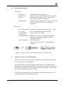
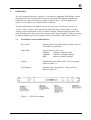
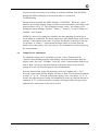
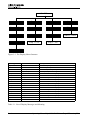
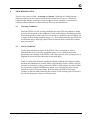
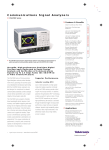
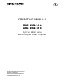
OPERATING MANUAL
OAS 1501-16 A
OAS 1501-16 B
O p t i C a T 1 5 0 0 Series
Erbium-Doped Fiber Amplifier
Richard Hirschmann GmbH & Co
Business department
Interactive Broadband Networks
Stuttgarter Strasse 4 - 51
D - 72654 Neckartenzlingen
Disclaimer
Every attempt has been made to make this material complete, accurate, and up-to-date. Users are
cautioned, however, that Richard Hirschmann GmbH & Co reserves the right to make changes
without notice and shall not be responsible for any damages, including consequential, caused by
reliance on the material presented, including, but not limited to, typographical, arithmetical, or listing
errors.
Copyright Information
© 1997 by Richard Hirschmann GmbH & Co
Richard Hirschmann GmbH & Co
Business department
Interactive Broadband Networks
Stuttgarter Strasse 45 - 51
D - 72654 Neckartenzlingen
0-2
Operating Manual OptiCaT 1500 Erbium-Doped Fiber Amplifier
1.
GENERAL INFORM ATION . . . . . . . . . . . . . . . . . . . . . . . . . . . . . . . . . . . . . . . . . . .
1.1 Scope of this M anual . . . . . . . . . . . . . . . . . . . . . . . . . . . . . . . . . . . . . . . . . . . . . .
1.2 General Description . . . . . . . . . . . . . . . . . . . . . . . . . . . . . . . . . . . . . . . . . . . . . . .
1.3 Physical Description . . . . . . . . . . . . . . . . . . . . . . . . . . . . . . . . . . . . . . . . . . . . . .
1.4 Features and Advantages of the OptiCaT 1500 Series . . . . . . . . . . . . . . . . . . . . .
1.5 Specifications . . . . . . . . . . . . . . . . . . . . . . . . . . . . . . . . . . . . . . . . . . . . . . . . . . . .
1.6 Functional Description . . . . . . . . . . . . . . . . . . . . . . . . . . . . . . . . . . . . . . . . . . . . .
1.7 Optical Receptacle Care and Handling . . . . . . . . . . . . . . . . . . . . . . . . . . . . . . . . . .
1.8 Service . . . . . . . . . . . . . . . . . . . . . . . . . . . . . . . . . . . . . . . . . . . . . . . . . . . . . . . . .
1.9 If You Need Help . . . . . . . . . . . . . . . . . . . . . . . . . . . . . . . . . . . . . . . . . . . . . . . . .
1.10 Safety Considerations . . . . . . . . . . . . . . . . . . . . . . . . . . . . . . . . . . . . . . . . . . . . . .
1.11 Electrostatic Sensitivity . . . . . . . . . . . . . . . . . . . . . . . . . . . . . . . . . . . . . . . . . . . .
1-1
1-1
1-1
1-1
1-2
1-2
1-3
1-4
1-4
1-5
1-5
1-5
2.
INSTALLATION . . . . . . . . . . . . . . . . . . . . . . . . . . . . . . . . . . . . . . . . . . . . . . . . . . . .
2.1 Examine the Equipment . . . . . . . . . . . . . . . . . . . . . . . . . . . . . . . . . . . . . . . . . . . .
2.2 Preparing the Equipment . . . . . . . . . . . . . . . . . . . . . . . . . . . . . . . . . . . . . . . . . . .
2.2.1 Environmental Requirements . . . . . . . . . . . . . . . . . . . . . . . . . . . . . . . . . . .
2.2.2 Equipment M ounting Requirement . . . . . . . . . . . . . . . . . . . . . . . . . . . . . .
2.2.3 Power Requirements . . . . . . . . . . . . . . . . . . . . . . . . . . . . . . . . . . . . . . . . .
2.3 Install the Equipment . . . . . . . . . . . . . . . . . . . . . . . . . . . . . . . . . . . . . . . . . . . . . .
2.4 M ake Electrical Connections . . . . . . . . . . . . . . . . . . . . . . . . . . . . . . . . . . . . . . . .
2.5 M ake Optical Connections . . . . . . . . . . . . . . . . . . . . . . . . . . . . . . . . . . . . . . . . . .
2.6 M ake Communications Connections (Optional) . . . . . . . . . . . . . . . . . . . . . . . . . .
2-1
2-1
2-1
2-1
2-2
2-2
2-2
2-2
2-3
2-3
3.
OPERATION . . . . . . . . . . . . . . . . . . . . . . . . . . . . . . . . . . . . . . . . . . . . . . . . . . . . . . .
3.1 Front Panel Controls and Indicators . . . . . . . . . . . . . . . . . . . . . . . . . . . . . . . . . . .
3.2 Rear Panel Connections . . . . . . . . . . . . . . . . . . . . . . . . . . . . . . . . . . . . . . . . . . . .
3.3 Startup and Normal Operation . . . . . . . . . . . . . . . . . . . . . . . . . . . . . . . . . . . . . . .
3.4 Output Power Adjustment . . . . . . . . . . . . . . . . . . . . . . . . . . . . . . . . . . . . . . . . .
3-1
3-1
3-2
3-2
3-3
4.
TROUBLESHOOTING . . . . . . . . . . . . . . . . . . . . . . . . . . . . . . . . . . . . . . . . . . . . . . . 4 - 1
4.1 Warning Conditions . . . . . . . . . . . . . . . . . . . . . . . . . . . . . . . . . . . . . . . . . . . . . . . 4 - 1
4.2 Alarm Conditions . . . . . . . . . . . . . . . . . . . . . . . . . . . . . . . . . . . . . . . . . . . . . . . . 4 - 1
5.
THEORY AND BLOCK DIAGRAM
6.
MODEL SPECIFICATIONS . . . . . . . . . . . . . . . . . . . . . . . . . . . . . . . . . . . . . . . . . . . 6 - 1
.................................... 5-1
Operating Manual OptiCaT 1500 Erbium-Doped Fiber Amplifier
0-3
1.
GENERAL INFORMATION
1.1
S cope of this Manual
This document describes the form, fit, and function of the OptiCaT 1500 Series
Erbium-Doped Fiber Amplifier (EDFA) and all acceptable standard options.
• Installing the unit
• Operating the unit
• Setting up the unit to suit individual needs
• Troubleshooting
• Theory of operation
• Repair Policy
1.2
General Description
The OptiCaT 1500 EDFA is an optical amplifier operating in the 1550 nm
wavelength region. These units are intended to function as either a booster or line
amplifier depending on the model.
980nm diode lasers are used to pump Erbium doped fiber to provide optical
amplification. Depending on model, optical isolators are used at both the input and
output of the amplifier. Tap couplers allow the measurement of the optical input
and output powers.
The unit can be powered from AC, DC, or conditioned external DC supplies,
configured as main or backup, depending on which powering option is ordered.
1.3
Physical Description
Figure 1-1 is an illustration of the OptiCaT 1500 EDFA, showing unit
measurements. The Optical Amplifier is a rack mounted 1U unit.
Height
Width
Depth
Weight
1.75" (44 mm), 1U
19" (483 mm)
20" chassis (508 mm), 21" (533 mm) with fans
20 lbs (9 kgs) max.
Operating Manual OptiCaT 1500 Erbium-Doped Fiber Amplifier
1-1
Figure 1-1 OptiCaT 1500 EDFA Unit
1.4
Features and Advantages of the 9100 S eries
• Models available with a wide range of optical output power.
• Low Noise Figure.
• User adjustable output power.
• Front panel display of status and configuration of the Optical Amplifier.
• LED status indicator.
• Remote status monitoring function via RS485 Interface.
• Wide range of electrical power options available.
• High reliability and a 1-year warranty.
1.5
S pecifications
Specifications for the specific OptiCaT 1500 Series model ordered are listed in
section 6. M ODEL SPECIFICATIONS.
1-2
Operating Manual OptiCaT 1500 Erbium-Doped Fiber Amplifier
1.6
Functional Description
Front Panel:
On/Off Key
LED indicator
Display
Activate/De-activate optical gain
Indicates status of unit (Normal, Warning, or Alarm)
Alphanumeric Dot Matrix LED, 1 line provides
status and configuration information.
up/down/select push buttons are used to select menu
items for display and to vary user adjustable
parameters.
Scroll buttons
Rear Panel:
Power entry module
AC option)
Terminal Block
Ground Stud
Communication port
Optical connectors
FC/APC
On/Off switch with standard 3-pin IEC AC (with
power socket with integrated fuse holder
4 post for DC power inputs
Dual RJ-11 jacks for use with RS-485 protocol.
Status monitoring with compatible Network
Management Software
fiber input/output
options: FC/APC, SC/APC, E-2000 bulkhead
connectors
SC/APC
E-2000
Figure 1-2 Optical Connectors Compatible with OpitCaT 1500 EDFA
1.7
Optical Connector Care and Handling
All optical connectors are shipped with end caps for protection and safety. Do not
remove the end caps until installation.
The optical connector’s surface is highly polished and free of foreign materials to
ensure low loss coupling and back reflection. Do not allow the optical connectors to
become dirty. Small traces of dirt will degrade transmission quality. Ensure that the
caps are on the optical connectors at all times.
It is absolutely critical that fiber optic connectors be cleaned each and every time
before connecting or reconnecting to anything.
Operating Manual OptiCaT 1500 Erbium-Doped Fiber Amplifier
1-3
Without proper maintenance practices, fiber optic systems will fail to function
properly. These performance degradation’s take many forms:
• Poor analog transmission quality
• Digital bit error rates increase
• Reduced optical power
• Receiver input power outside optimum operating range
• Dirty connectors may cause damage to their mated counterparts
It is recommended that RIFOCS Corporation 945/946 fiber optic connector cleaning
system be used for cleaning the optical connectors.
1.8
S ervice
High power lasers are contained within this unit. Dangerous AC voltages may be
present.
Do not attempt to modify or service any part of the system. If the system does not
meet its warranted specifications, or if a problem is encountered that requires service,
return the apparently faulty assembly to Hirschmann for evaluation in accordance
with Hirschmann 's warranty policy.
When returning an assembly for service, include the following information: Owner,
M odel Number, Serial Number, Return Authorization Number (obtained in advance
from Hirschmann Corporation's Customer Service Department), service required
and/or a description of the problem encountered.
1.9
If You Need Help
If you need additional help in installing or using the system, need additional copies of
this manual, or have questions about system options, please call Hirschmann´s
Service Center at +49 / 7127 / 14-1301.
1.10
S afety Considerations
When installing or using this product, observe all safety precautions during handling
and operation. Failure to comply with the following general safety precautions and
with specific precautions described elsewhere in this manual violates the safety
standards of the design, manufacture, and intended use of this product. Hirschmann
GmbH & Co assumes no liability for the customer's failure to comply with these
precautions.
1-4
Operating Manual OptiCaT 1500 Erbium-Doped Fiber Amplifier
Calls attention to a procedure or practice which, if ignored, may result in damage to
the system or system component. Do not perform any procedure preceded by a
CAUTION until described conditions are fully understood and met.
1.11
Electrostatic S ensitivity
Observe electrostatic precautionary procedures. (ESD = ElectroStatic Discharge)
The OptiCaT 1500 amplifier provides highly reliable performance when operated in
conformity with its intended design. However, it may be damaged by an electrostatic
charge inadvertently imposed by careless handling.
Static electricity can be conducted to the amplifier through the rear panel connectors.
When unpacking and otherwise handling the amplifier, follow ESD precautionary
procedures including use of grounded wrist straps, grounded workbench surfaces,
and grounded floor mats.
Exposure to electrostatic charge is greatly reduced after the amplifier chassis is
grounded.
Operating Manual OptiCaT 1500 Erbium-Doped Fiber Amplifier
1-5
2.
INS TALLATION
To install the equipment, perform the following steps, each of which is described in detail in
the rest of this section.
• Step 1. Examine the equipment for loss or damage that may have occurred during
shipping.
• Step 2. Prepare the operating environment.
• Step 3. Install the OptiCaT 1500 EDFA
• Step 4. M ake electrical connections
• Step 5. M ake RF connections
• Step 6. M ake optical connections
2.1
Examine the Equipment
• Carefully unpack the equipment. Be sure to check the packing material for small
parts
• Check the contents of package against the following list:
Package Contents
• OptiCaT 1500 EDFA
• Operation M anual
• Factory test data
• AC power cord (If AC option selected)
• If any of the equipment is missing or damaged, please notify Hirschmann
Corporation immediately.
2.2
Preparing the Equipment
2.2.1
Environmental Requirements
The OptiCaT 1500 EDFA has been designed to operate over a temperature
range of 0oC to 50oC. Hirschmann GmbH & Co recommends operating it at
an ambient temperature of 25oC (77oF).
The humidity should be kept below 95% non-condensing. If necessary,
equipment should be installed to maintain the temperature and humidity
within these limits.
Hirschmann GmbH & Co also recommends a low dust environment.
Operating Manual OptiCaT 1500 Erbium-Doped Fiber Amplifier
2-1
2.2.2
Equipment Mounting Requirement
The OptiCaT 1500 EDFA is 1 unit high and is designed to fit EIA standard
19 inch equipment cabinets. Hirschmann GmbH & Co recommends 1.75 inch
space above and below the unit.
2.2.3
Power Requirements
Depending on the option purchased, the unit can be powered from AC,
unregulated DC, or regulated external DC. If AC power is present, it will be
the main supply. The DC inputs can be configured as a backup or as the
main supply (if AC is not present).
Power Requirements are:
AC input
DC input
external DC input
90- 264 VAC, 50-440 Hz
21-60 VDC, floating
+24 VDC +/-0.5V
Noise and ripple less than
100 mV-pp above 100 kHz, less than 20 mVpp
below 100 kHz
40 W max.
Power Consumption:
2.3
Install the Equipment
M ount the OptiCaT 1500 EDFA in the equipment cabinet in the desired location.
2.4
Make Electrical Connections
When AC power is present, it will be the main supply. The
DC inputs can be configured as a backup or as the main
supply (if AC is not present) depending on the powering
option ordered.
The four available powering options of the unit are as follows:
• AC only
• DC only
• AC and DC
• 24V conditioned only
2-2
AC input and 24V conditioned input only
DC input and 24V conditioned input only
AC input, DC input, and 24V conditioned input
24V conditioned input only
Operating Manual OptiCaT 1500 Erbium-Doped Fiber Amplifier
Note: M ake heavy gauge wire connection between ground stud and chassis ground
before making electrical connections.
21 - 60 V DC input
Regulated Input
+24 V Gnd
Figure 2-1 DC Power Connections
2.5
Make Optical Connections
Ensure optical input signal is present.
M ake sure all connectors are clean before installing. Connect the input and output
fiber cables to the appropriate connectors on the rear of the unit. Optical connector
options are: FC/APC, E -2000, SC/APC with either pigtails or bulkhead connectors.
2.6
Make Communications Connections (Optional)
Status monitoring is available with compatible RS-485 Network M anagement
System through dual RJ-11 phone Jacks.
Operating Manual OptiCaT 1500 Erbium-Doped Fiber Amplifier
2-3
3.
OPERATION
The user front panel interface consists of a 16 character segmented LED display, a status
indicating LED, and 3 push buttons. The status indicating LED indicates whether the
conditions are normal, or whether a warning or alarm is active. The LED lights green,
amber, or red, respectively to indicate these conditions.
The three push buttons are marked with an up arrow (up), a down arrow (down), or
“select” (select, or enter). These buttons are used to navigate a menu (figure 3-3) that
displays system information on the 16 character display. During normal operation, and
when no buttons have been pressed, the display reads “Optical amplifier” When a warning
or alarm condition is present, the display shows a description of the problem (table 3-1).
3.1
Front Panel Controls and Indicators
Key switch
Optical gain section enable/disable switch - (key not
removable in on position)
Status LED
Tricolor (green, yellow, red)
GREEN - indicates normal operation
AM BER - indicates a warning condition
RED
- indicates an alarm condition
Display
Alphanumeric Dot Matrix LED - List of messages
shown in Table 3-1.
Scroll buttons
up/down/select push buttons - Menu structure
shown in Figure 3-1
Figure 3-1. EDFA Front Panel
Operating Manual OptiCaT 1500 Erbium-Doped Fiber Amplifier
3-1
3.2
Rear Panel Connections
Power entry module
(If AC ordered)
On/Off switch with standard
3-pin IEC AC power socket integrated fuse holder
Make sure the Key switch on the front panel is in
the “Off” position before turning the power on
switch to the “On” position.
Optical connectors
Fan
Terminal Block
Ground Stud
Communication port
Communications:
fiber input/output
options: FC/APC, E-2000, SC/APC
dual with shields
4 post for DC power inputs
dual RS-485 phone jacks
Status monitoring with compatible Network
Management Software
DA N G E R
INVISIBLE L A S E R RADIAT ION
A VO ID DIRECT E XPOSURE TO B EA M
PEAK POWER 2 00 m W
WAVEL ENGTH
15 50 n m
CLASS IIIb L ASER PRODUCT
THIS PRODUCT COM PL IES WITH 21 C FR
CHA PT E R I S U BCHAPTER J
Figure 3-2. EDFA Rear Panel
3.3
Startup and Normal Operation
With the Laser key in the “Off” position, turn on the rear panel electrical power.
When the EDFA is first powered up, it will go through a series of power-on selftests. During the self-test period, the push buttons are disabled, the display flashes
“Start-up,” and the LED is set to amber.
With the key in the “Off” position, the optical gain will be disabled and the input
optical signal will be throughput without any amplification or degradation.
To enable the optical gain section, turn the key switch to the “On” position. The
LED will switch to green and “1550 EDFA” will be displayed. If the EDFA does
3-2
Operating Manual OptiCaT 1500 Erbium-Doped Fiber Amplifier
not pass its self-test because of a warning or an alarm condition, then the EDFA
changes the LED and display as described in table 4-1 in Section 4
Troubleshooting.
During normal operation, the EDFA displays “1550 EDFA.” When the “select”
button is pressed, the display changes to show system information according to the
menu structure of Fig. 3-1. By repeatedly pressing “select,” the display cycles
through the menu headings “Optical,” “Pump 1,” “Pump 2,” on up to “Pump 4 if
installed,” and “System.”
In EDFA’s where fewer pumps are installed, the menu headings for those lasers
not installed are eliminated. The down button moves the display down in the menu
structure; if the bottom of the menu is reached, the display wraps back to the top.
For instance, if “Pump 1” is shown and the down button is pressed, then the
display shows the pump 1 laser bias current. The up button moves the display up
the menu structure.
3.4
Output Power Adjustment
To adjust the output power repeatedly press the “select” button until the
“Optical” menu heading appears in the display. Press the down button until the
display reads “Pwr Adj = xx.xdBm.” Press the “select” button and the display will
start to flash. Use the up and down button to adjust the power to the desired
setting. Press the select button again to save the adjustment.
Press the down button again, and the display will read “Update Adj. = Y/N.”
Press the select button and the display will start to flash. Use the up/down buttons
to select “Y” or “N.” Press the select button again to save your choice. If “Y” is
chosen, the adjusted power setting will automatically come up each time the unit is
turned on. If “N” is chosen, the power setting will change back to the previously
updated value when power to the unit is cycled.
Operating Manual OptiCaT 1500 Erbium-Doped Fiber Amplifier
3-3
1550 EDFA
Optical
Pump 1
Pump 2
System
P in = xx.xdBm
I bias 1 = xxxmA
I bias 2 = xxxmA
SN = xxxx
P out = xx.xdBm
I TEC 1 = x.xxA
I TEC 2 = x.xxA
Address = xxxxx
Pwr Adj = xx.xdBm
Temp 1 = xxC
Temp 2 = xxC
Update Adj = Y/N
Figure 3-3. The Display Menu Structure
Heading
Item
Description
Optical
Pin=xx.xdBm
Pout=xx.xdBm
Pwr Adj = xx.xdBm
Update Adj = Y/N
I bias 1=xxxmA
I TEC 1=x.xxA
Temp 1=xxC
I bias 2=xxxmA
I TEC 2=x.xxA
Temp 2=xxC
I bias 3=xxxmA
I TEC 3=x.xxA
Temp 3=xxC
I bias 4=xxxmA
I TEC 4=x.xxA
Temp 4=xxC
SN = xxx
Address=xxxxx
shows the optical power into the EDFA
shows the optical power out of the EDFA
shows the adjusted optical power out of the EDFA
saves adjusted power setting to non-volatile memory
shows the bias current to pump laser 1
shows the TEC current for pump laser 1
shows the temperature of pump laser 1
shows the bias current to pump laser 2
shows the TEC current for pump laser 2
shows the temperature of pump laser 2
shows the bias current to pump laser 3
shows the TEC current for pump laser 3
shows the temperature of pump laser 3
shows the bias current to pump laser 4
shows the TEC current for pump laser 4
shows the temperature of pump laser 4
serial number of the transmitter
network address of the transmitter
Pump 1
Pump 2
Pump 3
Pump 4
System
Table 3-1. List of Display Messages and Meaning
3-4
Operating Manual OptiCaT 1500 Erbium-Doped Fiber Amplifier
4.
TROUBLES HOOTING
There are two types of faults - warnings and alarms. Warnings are conditions that
indicate problems, but do not necessarily result in a total loss of service. Alarms are
conditions that indicate a total loss of service. Based on the condition of the alarm or
warning, different indicators will be affected. These are described below.
4.1
Warning Conditions
When the EDFA is in the warning condition, the status LED will change to amber,
and a brief description of the condition is listed on the display. Warnings generally
do not halt operation of the unit, but correspond to a parameter that is slightly out
of range. If the warning condition ceases, i.e. , the relevant parameter goes back into
its allowable range, the display and LED will return to their normal state without
user intervention.
4.2
Alarm Conditions
Alarms generally halt operation of the EDFA. They correspond to either a
parameter that is far out of the acceptable range, or to a condition that could
potentially cause damage to the EDFA. If the alarm persists after cycling power or
toggling the keyswitch, then the alarm is activated again.
Table 4-1 defines the different warning and alarm conditions, the display readout,
and how the conditions are cleared. Some critical alarms, such as “Alarm: self test,”
can only be cleared by cycling power to the EDFA. Other alarms are cleared when
the keyswitch is toggled off and then on again or are self clearing if the relevant
parameter returns to a normal range. With warnings, the EDFA will simply
continue to function while indicating the warning, or the warning will clear itself if
the relevant parameter returns to a normal range.
Operating Manual OptiCaT 1500 Erbium-Doped Fiber Amplifier
4-1
Note: When the keyswitch is in the “off” position, the LED is amber and the display
reads “Stand By” to indicate the standby mode
EDFA Condition
Power on/key on
Display Readout
1550 EDFA
LED Color
Green
Description
normal operation
Warning
Power on/key off
Standby
Amber
Initialization
Start Up
Amber
Warn: Ibias Y hi
Amber
Warn: pump Y
cold
Amber
Warn: pump Y hot
Amber
pump laser temperature
high
Input optical power low,
key on
Warn: input low
Amber
low 1550nm input
power,
still operate amplifier
Failed self test
Alarm:self test
Red
cycle power to clear
ITEC>ITEC_max
Alarm: TEC Y
Red
pump TEC failure,
cycle power to clear
Ibias>Ibias_max
Alarm: Ibias Y
Red
pump bias failure,
key switch reset
Alarm: no input
Red
disable optical gain
section,
self clear if optical
power on
Alarm: output low
Red
low output power,
toggle keyswitch to
clear
Ibias high
Laser temperature low
Laser temperature hi
standby until keyswitch
turned on
key and buttons
disabled
during start up
Ibias is near the
maximum rating for
laser; laser may be
degrading
pump laser temperature
low
Alarm
Input optical power off,
key on
Optical output power low
Table 4-1. Warnings and Alarms
(Shows display and LED indications and what the system does in response.)
If any problems are encountered which cannot be corrected, please contact Hirschmann
Corporation at +49 / 7127 / 14-1301
4-2
Operating Manual OptiCaT 1500 Erbium-Doped Fiber Amplifier
5.
THEORY AND BLOCK DIAGRAM
The OptiCaT 1500 EDFA block diagram is shown in Fig 5-1. Depending on model,
isolators are used at both the input and output to prevent optical reflections from feeding
back into the amplifier which can degrade performance. Tap couplers at both the input and
output are used to monitor the power of the incoming and amplified output signal.
Gain occurs in a section of Erbium doped fiber which is “pumped” by light from 980 nm
lasers. The erbium ions absorb the 980nm pump light and re-emit light which is in phase
and at the same wavelength as the input signal. The amount of gain is dependent on both
the incoming signal power and the pump power.
980nm Pump
Laser(s)
Photodiode
Photodiode
Output
Input
Input
Tap
Erbium
Input
Isolator Gain
Output Output
Isolator Tap
Note: Isolators may or may not be present.
Figure 5-1. OptiCaT 1500 Amplifier Block Diagram
Operating Manual OptiCaT 1500 Erbium-Doped Fiber Amplifier
5-1
6.
MODEL S PECIFICATIONS
Parameter
OAS 1501-16 A
Output Power
Noise Figure (max) 1)
Operating Wavelength
Polarization Sensitivity
Input Optical Return Loss
Output Optical Return
Loss
Operating Temperature
Power Consumption (max)
16 dBm
5.5 dB
OAS 1511-16 B
16 dBm
5.0 dB
1540 - 1560 nm
<0.2 dB
>50 dB
No spec
>50 dB
0 - 50 C
40 W
1) : At 6 dBm input power
Table 6-1. Performance Specifications
Operating Manual OptiCaT 1500 Erbium-Doped Fiber Amplifier
6-1