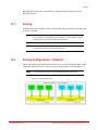
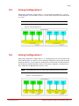
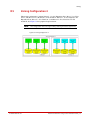
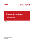
1
StorageScaler 2460
Installation and User Guide
SS2460
Document No.: 96-00290-001
Document Revision: A1
Important Information
Information in this document is subject to change without notice and does not represent a commitment on
the part of DataDirect Networks, Inc. No part of this manual may be reproduced or transmitted in any form
or by any means, electronic or mechanical, including photocopying and recording, for any purpose other
than the purchaser’s personal use without the written permission of DataDirect Networks, Inc.
© 2013 DataDirect Networks, Inc. All rights reserved.
DataDirect Networks, the DataDirect Networks logo, DirectOS, DirectProtect, EXAScaler, GRIDScaler,
Information in Motion, NAS Scaler, NoFS, ObjectAssure, SATAssure, Silicon Storage Appliance, S2A, Storage
Fusion Architecture, SFA, Storage Fusion Fabric, xSTREAMScaler, Web Object Scaler, WOS are registered
trademarks or trademarks of DataDirect Networks, Inc. All other brand and product names are trademarks
of their respective holders.
DataDirect Networks makes no warranties, express or implied, including without limitation the implied
warranties of merchantability and fitness for a particular purpose of any products or software. DataDirect
Networks does not warrant, guarantee or make any representations regarding the use or the results of the
use of any products or software in terms of correctness, accuracy, reliability, or otherwise. The entire risk as
to the results and performance of the product and software are assumed by you. The exclusion of implied
warranties is not permitted by some jurisdictions; this exclusion may not apply to you.
In no event will DataDirect Network, their directors, officers, employees, or agents (collectively DataDirect
Networks) be liable to you for any consequential, incidental, or indirect damages, including damages for loss
of business profits, business interruption, loss of business information, and the like, arising out of the use or
inability to use any DataDirect product or software even if DataDirect Networks has been advised of the
possibility of such damages by you. Because some jurisdictions do not allow the exclusion or limitation of
liability for consequential or incidental damages, these limitations may not apply to you. DataDirect
Networks liability to you for actual damages from any cause whatsoever, and regardless of the form of the
action (whether in contract, tort including negligence, product liability or otherwise), is limited to the sum
you paid for the DataDirect product or software.
Document Number 96-00290-001 Rev. A1
April 2013
96-00290-001 Rev. A1
DataDirect Networks StorageScaler 2460 User Guide | ii
Important Information
STANDARD WARRANTY
Definitions: This two-year limited warranty applies to the following DataDirect Networks network infrastructure and
individual SAN solution components that include: Silicon Storage Appliance Hardware, Drive Modules, RAID Hardware
Components, Storage Hardware Components, and Disk Drive Docking Bays and Enclosures (hereinafter “DataDirect
Networks Products”). Fibre Channel Interface Kits, SCSI Interface Kits, Host Adapters and Networking Products are
limited to a 90-day warranty. Software bundled or included with DataDirect Networks solutions are furnished exclusively
under the terms of the applicable license agreements.
Warranty: DataDirect Networks warrants that the DataDirect Networks Products accompanied by this limited Warranty
are free from defects in material and workmanship for a period of two years from the date of original purchase from
DataDirect Networks or an authorized DataDirect Networks reseller. During the term of this Warranty, DataDirect
Networks will, at its option, repair or replace any defective parts of the DataDirect Networks products purchased under
this Warranty at no additional charge. Repair parts or replacement DataDirect Networks products will be furnished on
an exchange basis, and will be either reconditioned or new. When returning the DataDirect Networks products, the
Purchaser must prepay any shipping charges. In addition, the Purchaser is responsible for insuring the products returned
and assumes the risk of loss during shipment.
Warranty Claim Requirements: Purchaser claims made pursuant to this Warranty must conform to the following
requirements:
1. The DataDirect Networks products must be returned to (a) an Authorized DataDirect Networks Servicing Reseller in
the country of original purchase, or (b) a DataDirect Networks facility which performs Warranty service in the country
of original purchase, or (c) an Authorized DataDirect Networks Third Party Service Provider in the country of original
purchase.
2. The Purchaser must provide proof of purchase and date of purchase from DataDirect Networks or an Authorized
DataDirect Networks Reseller.
3. The Purchaser may request information on how to obtain warranty service by contacting any Authorized DataDirect
Networks Reseller, or by writing to the Warranty Service Department, DataDirect Networks, 9351 Deering Avenue,
Chatsworth, CA 91311.
Disclaimers: THIS LIMITED WARRANTY DOES NOT APPLY TO ANY DATADIRECT NETWORKS PRODUCTS WHICH
HAVE BEEN DAMAGED OR RENDERED DEFECTIVE (a) AS A RESULT OF ACCIDENT, MISUSE, OR ABUSE; (b) BY
THE USE OF PARTS NOT MANUFACTURED OR SOLD BY DATADIRECT NETWORKS; (c) BY MODIFICATION
WITHOUT THE WRITTEN PERMISSION OF DATADIRECT NETWORKS, OR (d) AS A RESULT OF SERVICE BY
ANYONE OTHER THAN DATADIRECT NETWORKS, AN AUTHORIZED DATADIRECT NETWORKS SERVICING
RESELLER, OR AN AUTHORIZED DATADIRECT NETWORKS THIRD PARTY SERVICE PROVIDER.
EXCEPT AS EXPRESSLY SET FORTH ABOVE, DATADIRECT NETWORKS MAKES NO OTHER WARRANTIES,
EXPRESS OR IMPLIED, INCLUDING, BUT NOT LIMITED TO, ANY IMPLIED WARRANTIES OF MERCHANTABILITY
AND FITNESS FOR PURPOSE, AND DATADIRECT NETWORKS EXPRESSLY DISCLAIMS ALL WARRANTIES NOT
STATED HEREIN. IN THE EVENT THE PRODUCTS ARE NOT FREE FROM DEFECTS AS WARRANTED ABOVE, THE
PURCHASER'S SOLE REMEDY SHALL BE REPAIR OR REPLACEMENT AS PROVIDED ABOVE. UNDER NO
CIRCUMSTANCES WILL DATADIRECT NETWORKS BE LIABLE TO THE PURCHASER, OR TO ANY USER, FOR ANY
DAMAGES, EXPENSES, LOST PROFITS, LOST SAVINGS, DAMAGE TO OR REPLACEMENT OF EQUIPMENT AND
PROPERTY, COSTS OF RECOVERING, REPROGRAMMING, OR REPRODUCING ANY PROGRAM OR DATA STORED
IN OR USED WITH THE PRODUCTS, OR OTHER DAMAGES ARISING OUT OF THE USE OR INABILITY TO USE THE
DATADIRECT NETWORKS PRODUCTS.
ANY IMPLIED WARRANTIES ARE LIMITED TO THE TERMS OF THIS EXPRESS LIMITED WARRANTY. SOME
STATES DO NOT ALLOW THE EXCLUSION OR LIMITATION OF INCIDENTAL OR CONSEQUENTIAL DAMAGES FOR
CONSUMER PRODUCTS, AND SOME STATES DO NOT ALLOW LIMITATIONS ON HOW LONG AN IMPLIED
WARRANTY LASTS, SO THE ABOVE LIMITATIONS OR EXCLUSIONS MAY NOT APPLY TO YOU. THIS WARRANTY
GIVES YOU SPECIFIC LEGAL RIGHTS, AND YOU MAY ALSO HAVE OTHER RIGHTS WHICH VARY FROM STATE TO
STATE.
96-00290-001 Rev. A1
DataDirect Networks StorageScaler 2460 User Guide | iii
About this Guide
This user guide explains how to install, configure, and use the DataDirect Networks
StorageScaler 2460 enclosure.
This user guide assumes that you are familiar with Serial Attached SCSI (SAS), Serial ATA
(SATA) technology, computer hardware, data storage, and network administration
terminology and tasks.
Terminology Used in this Guide
Because this user guide provides information that can be used to manage one or more
SS2460 enclosures in a variety of configurations, the generic term “storage space” is used to
refer to the controller, disk drives, and enclosures being used together for data storage.
Many of the terms and concepts referred to in this user guide are known to computer users
by multiple names. In this user guide, this terminology is used:
• I/O Controller (also known as an I/O module, or controller)
• Disk drive (also known as hard disk, hard drive, or hard disk drive)
• HBA (also known as Host Bus Adapter or SAS/SATA Adapter)
96-00290-001 Rev. A1
DataDirect Networks StorageScaler 2460 User Guide | iv
Table of Contents
Chapter 1
Introduction
Chapter 2
Installation
Chapter 3
Monitoring Your
SS2460
96-00290-001 Rev. A1
1.1
Kit Contents . . . . . . . . . . . . . . . . . . . . . . . . . . . . . . . . . . . . . . . . . . . . . . . . . . . . . . . . . . . . . . . . . . 2
1.2
Disk Drive Specifications . . . . . . . . . . . . . . . . . . . . . . . . . . . . . . . . . . . . . . . . . . . . . . . . . . . . 2
1.3
Cable Specifications . . . . . . . . . . . . . . . . . . . . . . . . . . . . . . . . . . . . . . . . . . . . . . . . . . . . . . . . . 2
1.4
Enclosure Components and Features . . . . . . . . . . . . . . . . . . . . . . . . . . . . . . . . . . . . . . . 3
1.5
SAS I/O Controllers . . . . . . . . . . . . . . . . . . . . . . . . . . . . . . . . . . . . . . . . . . . . . . . . . . . . . . . . . . 3
1.6
Disk Drives and Drive Carriers . . . . . . . . . . . . . . . . . . . . . . . . . . . . . . . . . . . . . . . . . . . . . . . 4
1.7
1.7.1
Advanced Power and Cooling (APC) Units . . . . . . . . . . . . . . . . . . . . . . . . . . . . . . . . . . 5
Maintaining Correct Airflow and Cooling. . . . . . . . . . . . . . . . . . . . . . . . . . . . . . . 6
1.8
1.8.1
1.8.2
1.8.3
1.8.4
1.8.5
1.8.6
1.8.6.1
Connection and Configuration Options . . . . . . . . . . . . . . . . . . . . . . . . . . . . . . . . . . . . 6
Basic Configuration–Single Controller System. . . . . . . . . . . . . . . . . . . . . . . . . . 6
Basic Configuration – Dual Controller System . . . . . . . . . . . . . . . . . . . . . . . . . . 7
Expansion Configuration – Single Controller System . . . . . . . . . . . . . . . . . . . 7
Expansion Configuration – Dual Controller System . . . . . . . . . . . . . . . . . . . . . 7
Daisy-Chain Configuration – Single Controller System . . . . . . . . . . . . . . . . . . 8
Daisy-Chain Configuration – Dual Controller System . . . . . . . . . . . . . . . . . . . 8
Daisy-Chain Limitations . . . . . . . . . . . . . . . . . . . . . . . . . . . . . . . . . . . . . . . . . . . . . . . . . . . . . 8
2.1
Installation Checklist . . . . . . . . . . . . . . . . . . . . . . . . . . . . . . . . . . . . . . . . . . . . . . . . . . . . . . . . 11
2.2
Preparing for Installation . . . . . . . . . . . . . . . . . . . . . . . . . . . . . . . . . . . . . . . . . . . . . . . . . . . 11
2.3
Installing the SS2460 into a Rack . . . . . . . . . . . . . . . . . . . . . . . . . . . . . . . . . . . . . . . . . . . 11
2.4
Installing the Disk Drives . . . . . . . . . . . . . . . . . . . . . . . . . . . . . . . . . . . . . . . . . . . . . . . . . . . 14
2.5
2.5.1
2.5.2
Connecting the SS2460 Enclosure . . . . . . . . . . . . . . . . . . . . . . . . . . . . . . . . . . . . . . . . . 15
Connecting to the Host System . . . . . . . . . . . . . . . . . . . . . . . . . . . . . . . . . . . . . . . 15
Connecting Additional SS2460 Enclosures . . . . . . . . . . . . . . . . . . . . . . . . . . . . 15
2.6
Powering On . . . . . . . . . . . . . . . . . . . . . . . . . . . . . . . . . . . . . . . . . . . . . . . . . . . . . . . . . . . . . . . . 17
3.1
Monitoring the Enclosure . . . . . . . . . . . . . . . . . . . . . . . . . . . . . . . . . . . . . . . . . . . . . . . . . . 19
3.2
Monitoring the Controllers . . . . . . . . . . . . . . . . . . . . . . . . . . . . . . . . . . . . . . . . . . . . . . . . . 20
3.3
Monitoring the Disk Drives . . . . . . . . . . . . . . . . . . . . . . . . . . . . . . . . . . . . . . . . . . . . . . . . . 21
3.4
Monitoring the APC Units . . . . . . . . . . . . . . . . . . . . . . . . . . . . . . . . . . . . . . . . . . . . . . . . . . 22
DataDirect Networks StorageScaler 2460 User Guide | v
Table of Contents
Chapter 4
Solving Problems
4.1
General Troubleshooting Tips . . . . . . . . . . . . . . . . . . . . . . . . . . . . . . . . . . . . . . . . . . . . . . 24
4.2
Replacing a Controller . . . . . . . . . . . . . . . . . . . . . . . . . . . . . . . . . . . . . . . . . . . . . . . . . . . . . . 24
4.3
Removing a Disk Drive (or Blank Drive Carrier) . . . . . . . . . . . . . . . . . . . . . . . . . . . . 25
4.4
Replacing an APC Unit . . . . . . . . . . . . . . . . . . . . . . . . . . . . . . . . . . . . . . . . . . . . . . . . . . . . . . 27
Appendix A
Technical Specifications. . . . . . . . . . . . . . . . . . . . . . . . . . . . . . . . . . . . . . . . . . . . . . . . . . . . . . . . . . . . . 28
A.1
General Specifications. . . . . . . . . . . . . . . . . . . . . . . . . . . . . . . . . . . . . . . . . . . . . . . . .29
A.2
Regulatory Compliance Statements. . . . . . . . . . . . . . . . . . . . . . . . . . . . . . . . . . . .30
A.3
Regulatory Agency Compliance . . . . . . . . . . . . . . . . . . . . . . . . . . . . . . . . . . . . . . .31
Appendix B
Zoning . . . . . . . . . . . . . . . . . . . . . . . . . . . . . . . . . . . . . . . . . . . . . . . . . . . . . . . . . . . . . . . . . . . . . . . . . . . . . . . 33
B.1
Zoning . . . . . . . . . . . . . . . . . . . . . . . . . . . . . . . . . . . . . . . . . . . . . . . . . . . . . . . . . . . . . . .34
B.2
Zoning Configuration 1 (Default) . . . . . . . . . . . . . . . . . . . . . . . . . . . . . . . . . . . . . .34
B.3
Zoning Configuration 2 . . . . . . . . . . . . . . . . . . . . . . . . . . . . . . . . . . . . . . . . . . . . . . .35
B.4
Zoning Configuration 3 . . . . . . . . . . . . . . . . . . . . . . . . . . . . . . . . . . . . . . . . . . . . . . .35
B.5
Zoning Configuration 4 . . . . . . . . . . . . . . . . . . . . . . . . . . . . . . . . . . . . . . . . . . . . . . .36
Appendix C
Safety Notices . . . . . . . . . . . . . . . . . . . . . . . . . . . . . . . . . . . . . . . . . . . . . . . . . . . . . . . . . . . . . . . . . . . . . . . 37
C.1
General Cautions and Notes . . . . . . . . . . . . . . . . . . . . . . . . . . . . . . . . . . . . . . . . . . .38
C.2
Installation Cautions and Notes. . . . . . . . . . . . . . . . . . . . . . . . . . . . . . . . . . . . . . . .38
Contacting Technical Support & Shipping Instructions . . . . . . . . . . . . . . . . . . . . . . . . . . . . . . . . . . . . . . . . . . . . . . . . 40
96-00290-001 Rev. A1
DataDirect Networks StorageScaler 2460 User Guide | vi
Chapter 1
Introduction
96-00290-001 Rev. A1
DataDirect Networks StorageScaler 2460 User Guide | 1
Introduction
This chapter describes the features of your StorageScaler 2460 enclosure and shows you
how you can upgrade your enclosure as your storage requirements change. It also lists the
contents of the StorageScaler 2460 enclosure kit, and describes additional hardware
requirements.
1.1
Kit Contents
• DataDirect Networks StorageScaler 2460 enclosure
• Two power cords
• Rackmount kit
• 24 Drive Carriers
• User Documentation CD
1.2
Disk Drive Specifications
The StorageScaler 2460 enclosure supports up to 24-2.5" SAS or SATA disk drives (see
Section 1.6).
Disk drives must be qualified by DataDirect Networks and meet these specifications:
• 7200, 10,000, or 15,000 rpm
• Hot-swap/hot-plug support
• SATA or SAS device plug connector
• 6 Gb/sec or 3 Gb/sec data rate
• 2.5" form factor
• (SAS disk drives) Upgradable disk drive firmware
1.3
Cable Specifications
To connect your StorageScaler 2460 enclosure, use high-quality SAS cables that meet these
length requirements:
• Minimum length: 0.5 meters
• Maximum length: 3 meters
NOTE :
The actual cable length supported is determined by the maximum cable
length supported by the HBA used. Refer to your HBA documentation to
verify the maximum cable length supported.
For updated disk drive information or to purchase approved SAS cables, please contact your
DataDirect Networks sales representative.
96-00290-001 Rev. A1
DataDirect Networks StorageScaler 2460 User Guide | 2
Introduction
1.4
Enclosure Components and Features
The main features of the enclosure are shown in Figure 1 and Figure 2.
Figure 1. StorageScaler 2460 Front View
Drive Carrier
Drive Carrier LEDs
Enclosure LEDs
Figure 2. StorageScaler 2460 Rear View
Slot A: I/O Controller
Slot B: I/O Controller
Advanced Power and Cooling (APC) Units
1.5
LEDs
SAS I/O Controllers
The StorageScaler 2460 enclosure contains one or two SAS I/O controllers, which are
installed on the back of the enclosure. In the case of a single I/O controller system, the
controller is installed in Slot A (Figure 2).
Figure 3 shows the rear of the I/O controller, its connections, and LEDs.
Figure 3. Rear of I/O Controller, Connections, and LEDs
Controller LEDs
96-00290-001 Rev. A1
DataDirect Networks StorageScaler 2460 User Guide | 3
Introduction
Each controller has three SAS ports (Figure 4):
• Use the input ports (HOST 1 and HOST 2) to connect to the host systems.
• Use the expansion port (EXP) to connect to another StorageScaler 2460 enclosure. See
Section 1.8 for more information.
• When using the StorageScaler 2460 in a zoned configuration, the three SAS ports are
assigned drives specifically to separate host computers. Please refer to Appendix B for
supported zoned configurations.
Each controller also has eleven status LEDs, as described in Section 3.2, Monitoring the
Controllers.
To remove a controller from the enclosure, follow the instructions in Section 4.2.
Figure 4. Controller Slot Numbers
Slot B
Slot A
1.6
Disk Drives and Drive Carriers
The StorageScaler 2460 enclosure supports up to 24 SAS or SATA disk drives. For disk drive
requirements, see Section 1.2. Disk drives are hot-swappable.
Each disk drive is mounted in a drive carrier (Figure 5) with a push-button lever for quick
installation and removal.
Figure 5. Disk Drive in Drive Carrier
Lever Release Button
Status LEDs
96-00290-001 Rev. A1
DataDirect Networks StorageScaler 2460 User Guide | 4
Introduction
NOTE :
A disk drive must not be removed from its drive carrier. A disk drive removed
from its carrier is not covered by the hardware warranty.
NOTE :
All SATA disk drives installed in a dual-controller system require the use of a
2:1 SATA MUX assembly. Please contact your DataDirect Networks sales
representative to obtain the MUX cards.
Each drive carrier has three LEDs, which indicate status as described in Section 3.3,
Monitoring the Disk Drives.
To maintain proper airflow and cooling inside the enclosure, drive slots (Figure 6) cannot be
left empty. Blank drive carriers are available to fill empty drive slots.
Figure 6. Drive Slot Numbering
1.7
Advanced Power and Cooling (APC) Units
Each SS2460 enclosure is equipped with two APC units (Figure 7) located on the back of the
enclosure.
Figure 7. APC Unit
Power
Cord
Connector
LED
Power Switch
The cooling fans in each APC unit run on separate circuits from the power supply.
Therefore, if one APC unit fails, its fans continue to run on power supplied by the other APC
unit.
Each APC unit has four LEDs, which indicate status as described in Section 3.4, Monitoring
the APC Units.
APC units are hot-swappable. See Section 4.4, Replacing an APC Unit for more information.
96-00290-001 Rev. A1
DataDirect Networks StorageScaler 2460 User Guide | 5
Introduction
1.7.1
Maintaining Correct Airflow and Cooling
In addition to supplying power, the APC units maintain proper airflow and cooling within the
enclosure.
Because there are two APC units, the enclosure can continue to operate even if one APC unit
fails. The cooling fans in each APC unit run on separate circuits from the power supply. If one
APC unit fails, its fans continue to run on power supplied by the other APC unit.
However, for proper enclosure operation and cooling, two APC units with fully-functional
fans must be installed at all times. The enclosure can run temporarily (for no more than five
minutes) with a single APC unit while you install a new one—you must install a second APC
unit as quickly as possible to maintain correct airflow and cooling.
CAUTION !
1.8
Once you have removed a failed APC unit, you must replace it within five
minutes or the enclosure may overheat and shut down to prevent
hardware damage. This type of shutdown is immediate—unexpected
loss of data access and permanent data loss may occur.
Connection and Configuration Options
This section describes the different connection options for your SS2460 enclosure.
NOTE :
1.8.1
Unless otherwise noted, the enclosures in all these configurations support
SAS or SATA disk drives, but not a combination of both.
Basic Configuration–Single Controller System
Connect your SS2460 enclosure to a SAS/SATA HBA or SAS/SATA RAID card in a single host
system (Figure 8).
Figure 8. StorageScaler 2460 Single Host System
Host
StorageScaler 2460 Enclosure
As your storage space requirements change, you can upgrade and expand this basic
configuration.
NOTE :
96-00290-001 Rev. A1
In single I/O controller configurations the controller must be installed in Slot
A (on the left side of the enclosure as seen from the back of the enclosure).
To install or remove an I/O controller, see Section 4.2.
DataDirect Networks StorageScaler 2460 User Guide | 6
Introduction
1.8.2
Basic Configuration – Dual Controller System
Connect your SS2460 enclosure to two SAS/SATA HBAs in a dual host system (Figure 9).
Figure 9. StorageScaler 2460 Dual Host System
StorageScaler 2460 Enclosure
Host
1.8.3
Host
Expansion Configuration – Single Controller System
Connect your SS2460 enclosure to a SAS/SATA HBA or SAS/SATA RAID card in a single host
system, then connect a second SS2460 enclosure to the first enclosure using the expansion
port on the I/O controller (Figure 10).
Figure 10. SS2460 Expansion Configuration - Single Controller System
Host
StorageScaler 2460 Enclosures
1.8.4
Expansion Configuration – Dual Controller System
Connect your SS2460 enclosure to two SAS/SATA HBAs in a dual host system, then connect
a second SS2460 enclosure to the first enclosure (Figure 11).
Figure 11. SS2460 Expansion Configuration - Dual Controller System
Host
Host
StorageScaler 2460 Enclosures
96-00290-001 Rev. A1
DataDirect Networks StorageScaler 2460 User Guide | 7
Introduction
1.8.5
Daisy-Chain Configuration – Single Controller System
Add multiple SS2460 enclosures to the first enclosure (Figure 12).
Figure 12. SS2460 Daisy-Chain Configuration (Single Controller)
StorageScaler 2460 Enclosures
Host
1.8.6
Daisy-Chain Configuration – Dual Controller System
Add multiple SS2460 enclosures to the first enclosure (Figure 13).
Figure 13. SS2460 Daisy-Chain Configuration - Dual Controller System
Host
Host
StorageScaler 2460 Enclosures
1.8.6.1
NOTE :
When daisy chaining a dual system, ensure that only controllers in Slot A are
daisy chained together, and that only controllers in Slot B are daisy chained
together.
NOTE :
All SATA disk drives installed in a dual-controller system require the use of a
2:1 SATA MUX assembly.
Daisy-Chain Limitations
A single host system can support up to 128 SAS addresses. When fully loaded with disk
drives, each SS2460 enclosure contains 26 SAS addresses (one per disk drive plus two for
the internal expanders).
96-00290-001 Rev. A1
DataDirect Networks StorageScaler 2460 User Guide | 8
Introduction
DataDirect Networks does not recommend daisy-chaining more than five enclosures to a
single host system, even if the enclosures are not fully loaded. Daisy-chains longer than five
enclosures are not supported.
NOTE :
96-00290-001 Rev. A1
The actual number of shelves that can be daisy-chained together is also
limited by the number of SAS devices supported by the HBA. Refer to your
HBA documentation to determine the maximum configuration supported.
DataDirect Networks StorageScaler 2460 User Guide | 9
Chapter 2
Installation
96-00290-001 Rev. A1
DataDirect Networks StorageScaler 2460 User Guide | 10
Installation
This chapter explains how to install, connect, and configure your StorageScaler 2460
enclosure.
2.1
Installation Checklist
❒ Plan and prepare for installation
❒ Install the enclosure in an equipment rack
❒ Install the disk drives
❒ Connect the cables
❒ Power on
2.2
Preparing for Installation
1.
Carefully read Appendix C, Safety Notices.
2.
Remove all the components from the packaging, inspect them for shipping damage,
then place them on an antistatic surface until you are ready to use them.
If you are using new disk drives, allow them to acclimate to room temperature before
installing them. Drives should be stored at room temperature for at least two hours
prior to use.
3.
When installing the enclosure in a rack:
- Ensure that you have these tools available:
• Phillips screwdriver
• Bubble level
- Arrange for someone to assist you during installation.
- Ensure ahead of time that you have chosen a suitable location for the enclosure and
the rack.
2.3
Installing the SS2460 into a Rack
To install your enclosure into a rack:
1.
Ensure that you have these rackmount kit components:
- Rails (one left, one right)
- 12 conical washers
- 10-M5x10mm Phillips pan-head screws
- 2-M5x10mm Phillips flat-head screws
- 6-M3x8mm Phillips flat-head screws
96-00290-001 Rev. A1
DataDirect Networks StorageScaler 2460 User Guide | 11
Installation
2.
Secure the rails to the front and rear supports of the rack, using the screws and conical
washers included in the kit (Figure 14).
Figure 14. Attach Rails to Rack
Rear Support
Secure Rear Rail
Secure Front Rail
Adjust Rail Length
to Fit Your Rack
Front Support
3.
Ensure that the rails are level on both sides and that both rails are installed at the same
height.
CAUTION !
4.
The enclosure is heavy. To avoid personal injury, have someone help you
lift it.
Slide the enclosure onto the rails, then push it all the way back until the rackmount ears
are flush against the vertical supports and the enclosure rests completely on the rails
(Figure 15).
Figure 15. Rackmount Ears
Rackmount Ear Rests
Against Vertical Support
96-00290-001 Rev. A1
DataDirect Networks StorageScaler 2460 User Guide | 12
Installation
5.
Secure both rackmount ears to the vertical supports using two of the M5x.8 screws as
shown in Figure 16.
Figure 16. Secure Rackmount Ears to Vertical Supports
Secure to Vertical Support
6.
Install the two plastic rack ear covers as shown in Figure 17. The rack installation is
complete at this point. Continue with Section 2.4, Installing the Disk Drives.
Figure 17. Plastic Rack Ear Covers
96-00290-001 Rev. A1
DataDirect Networks StorageScaler 2460 User Guide | 13
Installation
2.4
Installing the Disk Drives
CAUTION !
NOTE :
Acclimate new disk drives to room temperature before you install them.
Store drives at room temperature for two hours prior to use.
Combining SAS and SATA disk drives in this enclosure is not supported at
this time. Please use either SAS or SATA disk drives, but not both.
To install a disk drive:
1.
Press the release button to release the lever on the carrier.
2.
Hold the disk drive so that the LEDs are on the bottom and the lever is fully open.
3.
Slide the disk drive into the drive slot until the lever starts to close (Figure 18).
Figure 18. Disk Drive Inserted in Drive Slot
4.
Gently push the lever until it mates with the latch on the bottom of the drive slot and
clicks into place (Figure 19).
Figure 19. Lever Latched
NOTE :
96-00290-001 Rev. A1
To maintain proper airflow and cooling, a disk drive or a blank drive carrier
must be installed in every slot of the enclosure.
DataDirect Networks StorageScaler 2460 User Guide | 14
Installation
2.5
Connecting the SS2460 Enclosure
2.5.1
Connecting to the Host System
Use four external SAS cables to connect from your host adapter to the input port on your
DataDirect Networks I/O controller (Figure 20)(Figure 21).
Figure 20. Input Ports on I/O Controller
Figure 21. SAS Cable Connections to Hosts Example
NOTE :
When configuring for a single I/O unit, ensure that the I/O module is
plugged in the left slot (as viewed from the rear of the enclosure).
To connect additional SS2460 enclosures, continue with the next section. Otherwise, skip to
Section 2.6, Powering On.
2.5.2
Connecting Additional SS2460 Enclosures
You can daisy-chain up to five fully loaded SS2460 enclosures to a single host system
depending on the number of drives supported by the SAS HBA.
Enclosures installed with SAS disk drives and enclosures installed with SATA disk drives
can be included in the same daisy-chain.
NOTE :
96-00290-001 Rev. A1
All SATA disk drives installed in a dual-controller system require the use of a
2:1 SATA MUX assembly.
DataDirect Networks StorageScaler 2460 User Guide | 15
Installation
NOTE :
1.
When daisy chaining a dual system, ensure that only controllers in Slot A are
daisy chained together, and that only controllers in Slot B are daisy chained
together.
Use four external SAS cables to connect the expansion port to the input port on the
next SS2460 enclosure (Figure 22).
Figure 22. SAS Cable Connections to Additional SS2460 Enclosures
2.
To expand your configuration with multiple SS2460 enclosures, continue to connect
the expansion ports of the previous enclosure to the input port of the next enclosure
(Figure 23).
Figure 23. Multiple SS2460 Enclosure SAS Cable Connections
96-00290-001 Rev. A1
DataDirect Networks StorageScaler 2460 User Guide | 16
Installation
2.6
Powering On
DataDirect Networks recommends that you use an uninterruptible power supply (UPS) to
protect your enclosure.
Using the included power cords, connect each APC unit to an AC power source (Figure 24).
Figure 24. Power Cord Connector
Power-On Sequence
NOTE :
Once RAID arrays are configured, the enclosures should be powered on first
and allowed to complete drive spin-up and discovery prior to powering on
the hosts. Discovery is complete once the drive LEDs stop flashing.
If you are using a single enclosure configuration, the installation is complete and you can
begin using your SS2460 by turning on the power switch on each APC unit.
If you are using an expanded configuration, ensure that all expansion (secondary) SS2460
are powered on before powering on the primary SS2460 (the primary SS2460 is the one
connected directly to the hosts). This is required for the system to properly ‘see’ the
expansion SS2460.
Power-Off Sequence
NOTE :
Once RAID arrays are configured on the enclosures, the hosts should be
shut down prior to powering off the enclosures.
If you are using a single SS2460 configuration (primary SS2460 only), you can power down
the SS2460 by turning off the APC units.
If you are using an expanded configuration, ensure that the primary SS2460 is powered off
first, then the secondary SS2460.
96-00290-001 Rev. A1
DataDirect Networks StorageScaler 2460 User Guide | 17
Chapter 3
Monitoring Your SS2460
96-00290-001 Rev. A1
DataDirect Networks StorageScaler 2460 User Guide | 18
Monitoring Your SS2460
This chapter describes the status and activity LEDs that help you monitor the DataDirect
Networks StorageScaler 2460 enclosure and its components.
3.1
Monitoring the Enclosure
On the right side of the front of the SS2460 enclosure are four LEDs which indicate the status
of the whole enclosure (Figure 25). The LEDs are defined in Table 1.
When a failure occurs on a controller or APC unit, the enclosure LEDs indicate an enclosure
fault. Because the I/O controllers and APC units are on the back of the SS2460 enclosure,
where they may be hard to see, the enclosure LEDs can help you monitor all the components
in the enclosure.
Figure 25. Four Enclosure LEDs
Not Used
Enclosure Fault
Locate
Power
Table 1. Enclosure LED Indicator Description
96-00290-001 Rev. A1
LED
Color
Description
Enclosure Fault
Amber
Locate Beacon
Blue
Flashes - receiving Locate command
OFF - NOT receiving Locate command
Power
Green
ON - power is applied to enclosure
OFF - no power is applied to enclosure
ON - one or more detectable faults are present
OFF - no detectable faults
DataDirect Networks StorageScaler 2460 User Guide | 19
Monitoring Your SS2460
3.2
Monitoring the Controllers
Each controller has 11 status LEDs (Figure 26). The LEDs are defined in Table 2.
When a fault condition occurs on a controller, the enclosure LEDs indicate an enclosure
fault. Because the controllers are on the back of the enclosure where they may be hard to
see, always check controller status whenever the enclosure LEDs indicate a fault.
When the controller Fault LED illuminates, replace the controller (see Section 4.2).
Figure 26. Controller Status LEDs
Locate
SAS Link Fault
Ethernet LEDs
SAS Link
Established
I/O Fault
OK/Power
Table 2. I/O Controller LED Description
96-00290-001 Rev. A1
LED
Color
Description
OK / Power
Green
ON - the I/O module is properly booted and is functioning properly
OFF - the I/O module has detected an internal fault
I/O Module Fault
Amber
ON - an I/O module fault has been detected
OFF - no detectable I/O module faults
Locate Beacon
Blue
SAS Link
Established
Green
ON - a valid SAS link is established on at least one of the four SAS links
of the 4-wide SAS port
OFF - no valid SAS link is established on any of the four SAS links of the
4-wide SAS port
SAS Link Fault
Amber
ON - a detectable fault is present on at least one of the four SAS links of
the 4-wide SAS port
OFF - no detectable fault is present on any of the four SAS links of the
4-wide SAS ports
Ethernet Link
Green
ON - Ethernet link is up
OFF - Ethernet link is down
Ethernet Activity
Amber
Flashes - Ethernet link is active; the frequency that it will blink is 10 Hz
Flashes - receiving Locate command
OFF - NOT receiving Locate command
DataDirect Networks StorageScaler 2460 User Guide | 20
Monitoring Your SS2460
3.3
Monitoring the Disk Drives
Each disk drive carrier has three LEDs that indicate the status of the disk drive (Figure 27).
The LEDs are defined in Table 3.
NOTE :
If replacing a disk drive does not resolve a fault or failure indicated by the
Fault LED, replace the I/O controller (see Section 4.2).
Figure 27. Disk Drive Carrier LEDs
Status
Locate
Fault
Table 3. Disk Drive Carrier LED Description
96-00290-001 Rev. A1
LED
Color
Description
Locate Beacon
Blue
Fault
Amber
ON - a detectable fault is present
OFF - no detectable fault is present
Status
Green
ON - power is applied to disk
Flashing - indicates disk activities
Flashes - receiving Locate command
OFF - NOT receiving Locate command
DataDirect Networks StorageScaler 2460 User Guide | 21
Monitoring Your SS2460
3.4
Monitoring the APC Units
Each APC unit has four LEDs that indicate status (Figure 28) as described in Table 4 below.
When a failure occurs on an APC unit, the enclosure LEDs (see Section 3.1) indicate an
enclosure fault. Because the APC units are on the back of the enclosure where they may be
hard to see, always check the APC unit status whenever the enclosure LEDs indicate a fault.
Figure 28. APC Unit LEDs
Locate
Fault
DC OK
AC OK
Table 4. APC Unit LED Description
96-00290-001 Rev. A1
LED
Color
Description
DC OK
Green
Locate Beacon
Blue
Fault
Amber
ON - an APC unit fault has been detected
OFF - no detectable faults
AC OK
Green
ON - AC power is OK
OFF - AC power is not present
ON - DC power is OK
OFF - DC power is not present
Flashes - receiving Locate command
OFF - NOT receiving Locate command
DataDirect Networks StorageScaler 2460 User Guide | 22
Chapter 4
Solving Problems
96-00290-001 Rev. A1
DataDirect Networks StorageScaler 2460 User Guide | 23
Solving Problems
This chapter describes how to remove and replace failed or failing components of the
StorageScaler 2460 enclosure.
4.1
General Troubleshooting Tips
If you encounter difficulties installing or using your StorageScaler 2460 enclosure:
• Check all components on the enclosure—disk drives, APC units, I/O controllers—for
illuminated Fault LEDs. See Chapter 3 for more information.
• Ensure that all components are properly seated in their slots.
• Ensure that all cables are properly connected. If necessary, try using different SAS
cables.
• Ensure that both APC units are powered on.
• Try power cycling your equipment in this order:
a) Power off the host system.
b) Power off the SS2460 enclosure.
c) Power on the SS2460 enclosure.
d) Power on the host system.
• If you are using a single I/O controller, ensure that the controller is installed in Slot A
(on the left side as view from the back of the enclosure). Slot A is the default location
of the I/O controller. To move or replace the controller, see Section 4.2.
4.2
Replacing a Controller
CAUTION !
NOTE :
Although the controllers are hot-swappable, the safest way to replace a
controller without any risk of damage or data loss is with the enclosure
powered off.
I/O traffic to an I/O controller should be stopped before hot-swapping a
controller.
To remove the controller:
1.
If you are not doing a hot-swap, power off your equipment in this order:
a) Power off the host system.
b) Then, power off the SS2460 enclosure.
2.
Before you disconnect the cables, label each cable with the name of the port it connects
to. You will need this information when installing a new controller.
3.
Disconnect all the cables connected to the controller.
96-00290-001 Rev. A1
DataDirect Networks StorageScaler 2460 User Guide | 24
Solving Problems
4.
Pull the two release handles (Figure 29) and carefully slide the controller out of the bay.
Figure 29. Release Handles on I/O Controller
Release
Handles
5.
Gently slide a new controller into the bay until the black handles engage. Then press
the handles until the I/O canister latches into place.
6.
Connect the cables according to the notes you made when you removed the old
controller.
7.
If necessary, power on your equipment in this order:
a) Power on the SS2460 enclosure.
b) Then, power on the host system.
4.3
Removing a Disk Drive (or Blank Drive Carrier)
NOTE :
For disk drive installation instructions, see Section 2.4.
Important Safety Precautions
Before you remove a disk drive, read these important notes:
• To avoid data loss, stop all I/O activity on the disk drive before removing it. Removing
a disk drive during I/O activity could also hang the host system.
• Do NOT attempt to remove more than one disk drive or blank drive carrier at a time.
Damage to the drive carrier can occur if adjacent disk drives are removed at the same
time.
• To maintain proper airflow and cooling inside the enclosure, install either a disk drive
or a blank drive carrier into the empty drive bay as quickly as possible.
• If you will be installing a replacement disk drive, allow it to acclimate to room
temperature before continuing.
96-00290-001 Rev. A1
DataDirect Networks StorageScaler 2460 User Guide | 25
Solving Problems
Removing a Disk Drive or Blank Carrier
1.
Press the release button on the disk drive carrier to release the lever (Figure 30).
Figure 30. Release Button on Drive Carrier
Release Button
2.
Gently pull open the lever (Figure 31).
Figure 31. Drive Carrier with Lever Open
3.
If the enclosure is powered on, allow the disk drive to fully spin down (wait
approximately 30 seconds).
!
Warning
4.
Gently pull the disk drive out of the enclosure.
NOTE :
5.
96-00290-001 Rev. A1
Removing a disk drive before it has fully spun down may result in
disk drive damage.
Do not remove the disk drive from its drive carrier. A disk drive removed
from its carrier is not covered by the hardware warranty.
Immediately replace the disk drive or install a blank drive carrier to maintain correct
airflow and cooling. (See Section 2.4.)
DataDirect Networks StorageScaler 2460 User Guide | 26
Solving Problems
4.4
Replacing an APC Unit
If you remove a failed APC unit, you must replace it as quickly as possible (within five
minutes) to maintain correct airflow and cooling. Failed APC units can be hot-swapped.
If you do not have a replacement APC unit available for immediate installation, you must
power off the enclosure.
NOTE :
If the enclosure is still operational, the failed APC can be left installed to
maintain proper cooling until a replacement unit is available. The fans in
both APCs will continue to run at high speed until the APC unit is replaced.
To replace an APC unit:
1.
Power off the failed APC unit and remove the power cable.
If the enclosure is powered on, the fans in the other APC unit switch to high speed to
compensate for the reduced airflow.
2.
Push the release tab to the right and rotate the handle down (Figure 32).
Figure 32. Release Tab and Handle on APC Unit
Handle
Release T ab
3.
Slide the APC unit out of the bay. Do not use the release tab as a handle to lift or carry
the APC unit.
!
Warning
To avoid electrical shock, do NOT insert any instruments or tools
into the open APC slot.
4.
Gently slide a new APC unit into the bay until the handle rotates up and the release tab
clicks into place.
5.
Reconnect the power cable.
6.
Turn on the APC unit.
When proper airflow returns, the cooling fans in the other APC unit return to their
normal speed.
96-00290-001 Rev. A1
DataDirect Networks StorageScaler 2460 User Guide | 27
Appendix A
Technical Specifications
96-00290-001 Rev. A1
DataDirect Networks StorageScaler 2460 User Guide | 28
Technical Specifications
Here are the technical specifications for StorageScaler 2460.
NOTE :
A.1
Specifications subject to change without notice.
General Specifications
System
• 2U enclosure height (rack configurations)
• Up to 24 2.5" SAS or SATA disk drives (including SSD’s) per enclosure (6 Gb/sec or
3 Gb/sec)
Redundant Components
• Two APC units
• Up to 24 drives per enclosure
Field Replaceable Units
• Disk drives and drive carrier blanks
• APC units
• I/O modules
• I/O module slot blanks
Enclosure Physical Dimensions
• Height: 3.5" (89 mm)
• Width: 17.6" (447 mm)
• Depth: 19.3" (49 mm)
• Weight: up to 53 lbs (27 kg) maximum (with all drives installed)
Advanced Power and Cooling (APC) Units
• Input Voltage: 100–240 VAC
• Current Rating: 8.40 A (max)
• Input Frequency: 50/60 Hz
• Outputs:
- +5 V @ 28 A
- +12 V @ 43 A
• Maximum Average Output Power: 550 Watts
• Cooling: Variable speed blowers, two per APC for a total of four blowers per enclosure
NOTE :
96-00290-001 Rev. A1
APC units are hot-swappable.
DataDirect Networks StorageScaler 2460 User Guide | 29
Technical Specifications
A.2
NOTE :
SS2460 enclosures do not support single APC configurations due to thermal
requirements.
NOTE :
In the event of a power supply failure, the blowers in the failed supply will
continue to operate on power provided by the redundant APC unit.
Regulatory Compliance Statements
Temperature
• Operating: 5 °C to +40 °C
• Storage: 1 °C to +60 °C
• Transit: -40 °C to +60 °C
• Maximum Rate of Temperature Change: 20 °C per hour
Humidity
• Relative Humidity Operating: 20% to 80%, non-condensing
• Maximum Rate of Operational Humidity Change: 10% per hour
• Relative Humidity Storage: 10% to 80%, non-condensing
Altitude
• Altitude Operating: -200 to 10,000 feet
• Altitude Storage: -200 to 10,000 feet
Operational Shock
• 5 G half sine shock with pulse duration of 11 milliseconds or less.
Non-Operational Shock
• Half Sine Shock: 10 G half sine shock with pulse duration of 11 milliseconds or less.
Operational Vibration
• Sinusoidal vibration from 5 to 500 Hz at 0.16 G (0 to peak) at a sweep rate of 0.5 octaves
per minute.
• Random vibration from 5 to 500 Hz at 0.15 G (rms).
Non-Operational Vibration
• Sinusoidal vibration from 5 to 500 Hz at 0.75 G (half-sine) at a sweep rate of 0.5 octaves
per minute.
• Random vibration from 5 to 500 Hz at 0.5 G (rms).
96-00290-001 Rev. A1
DataDirect Networks StorageScaler 2460 User Guide | 30
Technical Specifications
Acoustics
Acoustic level shall not exceed a weighted sound power of 6.9 Bels at normal operation
tested to ISO7779.
A.3
Regulatory Agency Compliance
The SS2460 enclosure complies with the following Regulatory Agency requirements.
Product Safety Standards
• UL60950 Information Technology Equipment (US)
• CSA C22.2 No 60950 Information Technology Equipment (Canadian Law)
• EN 60950 Information Technology Equipment (European Norm)
• IEC60950 Information Technology Equipment
Product Safety Third Party Certifications
• cUL Listed USA
• TUV, GS Certified Germany
• TUV CB Certified
The SS2460 enclosure is CE and FCC marked to indicate compliance with the European Low
Voltage Directive and the EMC directive. The SS2460 enclosure is certified to Class A
emission limits.
1.
Product Safety: EN60950 ITE
2.
Emission Testing
- EN55024 Radiated and conducted emissions
- FCC, Part 15
- VCCI
3.
96-00290-001 Rev. A1
Immunity Testing:
- CENELEC EN55024
Light Industry
- CENELEC EN61000-4-2
Electrostatic Discharge
- CENELEC EN61000-4-3
Radiated Immunity
- CENELEC EN61000-4-4
Electrical Fast Transients (Burst)
- CENELEC EN61000-4-5
Transient (Surge)
- CENELEC EN61000-4-6
Conducted Immunity
- CENELEC EN61000-4-8
Power Frequency Magnetic Fields
- CENELEC EN61000-4-11
Power Line Interruption
- EN61000-3-2
Harmonic current emissions
- EN61000-3-3
Voltage fluctuations and flicker
DataDirect Networks StorageScaler 2460 User Guide | 31
Technical Specifications
Certification Marks
The SS2460 enclosure is labeled with the following compliance marks:
• United States FCC standard, 47 CFR Part 15
• Canadian standard, Industry Canada ICES-003
• CE Mark
• GS Mark
• TUV Safety Mark
Product Safety Certifications on Power Supplies as a Component
• UL Recognized Component (QQGQ2)
• TUV BG Certification
• CB Certificate and Report
• CE Mark
• BSMI
• CCC
96-00290-001 Rev. A1
DataDirect Networks StorageScaler 2460 User Guide | 32
Appendix B
Zoning
96-00290-001 Rev. A1
DataDirect Networks StorageScaler 2460 User Guide | 33
Zoning
This appendix describes the various zoning configurations that are supported on the
StorageScaler 2460.
B.1
Zoning
Zoning provides the capability to assign a group of drives in the enclosure to specific ports
on the I/O controllers.
B.2
NOTE :
Zoning configurations are pre-set at the factory and cannot be changed by
the user. Please contact DDN Sales if you wish to order SS2460s in specific
configurations other than the default shown below.
NOTE :
When using SATA drives in these configurations, a MUX interposer card is
required for the drive to operate with dual ports.
Zoning Configuration 1 (Default)
The default zoning state for the SS2460 enclosure is a no zoning configuration. This default
configuration allows all connected hosts access to all drives in the enclosure (Figure 33).
NOTE :
This configuration supports daisy-chaining enclosures (expansion).
Figure 33. Zoning Configuration 1
96-00290-001 Rev. A1
DataDirect Networks StorageScaler 2460 User Guide | 34
Zoning
B.3
Zoning Configuration 2
This zoning configuration “assigns” drives 1 - 12 to I/O module A and drives 13 - 24 to I/O
module B (Figure 34). I/O module A cannot access the drives assigned to I/O module B and
vice versa.
NOTE :
This configuration does not support daisy-chaining enclosures (expansion).
Figure 34. Zoning Configuration 2
B.4
Zoning Configuration 3
This zoning configuration “assigns” drives 1 - 8 to the Expansion Port on I/O module A and
I/O module B (Figure 35). Drives 9 - 16 are assigned to Zoning Port on I/O module A and I/O
module B. Drives 17 - 24 are assigned to the Input Port on I/O module A and I/O module B.
I/O modules A’s and B’s Zoning Port cannot see those drives assigned to the Input Port or
those assigned to the Expansion Port and vice versa.
NOTE :
This configuration does not support daisy-chaining enclosures (expansion).
Figure 35. Zoning Configuration 3
96-00290-001 Rev. A1
DataDirect Networks StorageScaler 2460 User Guide | 35
Zoning
B.5
Zoning Configuration 4
This zoning configuration “'assigns” drives 1 - 4 to the Expansion Port, drives 5 - 8 to Host
Port 1, and drives 9 - 12 to Host Port 2 on I/O module A. Drives 13 - 16 are assigned to the
Expansion Port, drives 17 - 20 to Host Port 1, and drives 21 - 24 to Host Port 2 on I/O
module B. See Figure 36 for a graphical representation.
NOTE :
This configuration does not support daisy-chaining enclosures (expansion).
Figure 36. Zoning Configuration 4
96-00290-001 Rev. A1
DataDirect Networks StorageScaler 2460 User Guide | 36
Appendix C
Safety Notices
96-00290-001 Rev. A1
DataDirect Networks StorageScaler 2460 User Guide | 37
Safety Notices
C.1
General Cautions and Notes
CAUTION !
Before touching any of the enclosure components, ground yourself and
take antistatic precautions. Use an antistatic wrist strap and a grounding
wire as a minimum precaution.
CAUTION !
Each storage subsystem must have a good electrical ground connection
through each power cord, through the building power grid to the point
of origin for the building power source entry.
CAUTION !
Circuit Overloading—Consideration should be given to the connection
of the equipment to the supply circuit and the effect that overloading of
circuits might have on overcurrent protection and supply wiring.
Appropriate consideration of equipment nameplate ratings should be
used when addressing the concern.
NOTE :
The maximum current draw is printed on the label on the back of the
storage subsystem.
CAUTION !
C.2
Reliable Earthing – Reliable earthing of rack-mounted equipment
should be maintained. Particular attention should be given to supply
connections other than direct connections to the branch circuit (for
example, use of power strips).
Installation Cautions and Notes
CAUTION !
96-00290-001 Rev. A1
To prevent personal injury and equipment damage, have someone
assist you during installation.
If necessary, reduce the weight of the storage subsystem by removing
the disk drives and APC units.
NOTE :
Ensure that your equipment rack is placed in a dust-free, well ventilated area
close to a UPS. Leave enough room behind the rack for servicing and to
allow for sufficient airflow.
NOTE :
For equipment racks with single or multiple storage subsystems installed,
the TMRA (manufacturers maximum recommended ambient temperature)
is 35 °C.
DataDirect Networks StorageScaler 2460 User Guide | 38
Safety Notices
96-00290-001 Rev. A1
NOTE :
Elevated Operating Ambient Temperature—When installed in a closed or
multi-unit rack assembly, the operating ambient temperature of the rack
environment may be greater than the room ambient. Therefore,
consideration should be given to installing the equipment in an
environment compatible with the manufacturer's maximum
recommended ambient (TMRA).
NOTE :
Mechanical Loading—Prevent instability by installing heavier items into the
bottom of the equipment rack. Mounting of the equipment in a rack should
be such that a hazardous condition is not achieved due to uneven loading.
DataDirect Networks StorageScaler 2460 User Guide | 39
Contacting Technical Support & Shipping Instructions
Please contact DataDirect Networks Support at any time for assistance. Support can be
reached by the following methods:
Web
Support Portal
Portal Assistance
Technical Support Bulletins
https://portal.ddnsupport.com
[email protected]
http://www.ddn.com/en/technical-support-bulletins
Email
Support Email
Mailing List Subscriptions
[email protected]
https://ddntsr.com/mailman/listinfo/tsr-announce
Telephone
DDN Worldwide Directory
http://www.ddn.com/en/support/contact-support
Product Shipping Instructions
If you are shipping the product to another location, always use the original packaging
provided with your unit(s).
If you are sending a product to DataDirect Networks for warranty or out of warranty repair,
you must obtain a Return of Materials Authorization (RMA) number from DataDirect
Networks Technical Support.
96-00290-001 Rev. A1
DataDirect Networks StorageScaler 2460 User Guide | 40