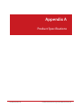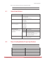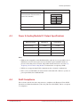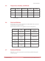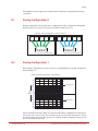
1
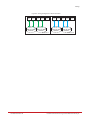
StorageScaler 8460 User Guide SS8460 Document No.: 96-30052-001 Revision: A4 Important Information Information in this document is subject to change without notice and does not represent a commitment on the part of DataDirect Networks, Inc. No part of this manual may be reproduced or transmitted in any form or by any means, electronic or mechanical, including photocopying and recording, for any purpose other than the purchaser’s personal use without the written permission of DataDirect Networks, Inc. © 2014 DataDirect Networks, Inc. All rights reserved. DataDirect Networks, the DataDirect Networks logo, DirectOS, DirectProtect, DirectMon, EXAScaler, GRIDScaler, Information in Motion, NAS Scaler, NoFS, ObjectAssure, SATAssure, Silicon Storage Appliance, S2A, Storage Fusion Architecture, SFA, Storage Fusion Fabric, Storage Fusion Xcelerator, SFX, xSTREAMScaler, Web Object Scaler, WOS are registered trademarks or trademarks of DataDirect Networks, Inc. All other brand and product names are trademarks of their respective holders. DataDirect Networks makes no warranties, express or implied, including without limitation the implied warranties of merchantability and fitness for a particular purpose of any products or software. DataDirect Networks does not warrant, guarantee or make any representations regarding the use or the results of the use of any products or software in terms of correctness, accuracy, reliability, or otherwise. The entire risk as to the results and performance of the product and software are assumed by you. The exclusion of implied warranties is not permitted by some jurisdictions; this exclusion may not apply to you. In no event will DataDirect Network, their directors, officers, employees, or agents (collectively DataDirect Networks) be liable to you for any consequential, incidental, or indirect damages, including damages for loss of business profits, business interruption, loss of business information, and the like, arising out of the use or inability to use any DataDirect product or software even if DataDirect Networks has been advised of the possibility of such damages by you. Because some jurisdictions do not allow the exclusion or limitation of liability for consequential or incidental damages, these limitations may not apply to you. DataDirect Networks liability to you for actual damages from any cause whatsoever, and regardless of the form of the action (whether in contract, tort including negligence, product liability or otherwise), is limited to the sum you paid for the DataDirect product or software. August 2014 96-30052-001 Rev. A4 DataDirect Networks StorageScaler 8460 User Guide | 2 Important Information STANDARD WARRANTY Definitions: This two-year limited warranty applies to the following DataDirect Networks network infrastructure and individual SAN solution components that include: Silicon Storage Appliance Hardware, Drive Modules, RAID Hardware Components, Storage Hardware Components, and Disk Drive Docking Bays and Enclosures (hereinafter “DataDirect Networks Products”). Fibre Channel Interface Kits, SCSI Interface Kits, Host Adapters and Networking Products are limited to a 90-day warranty. Software bundled or included with DataDirect Networks solutions are furnished exclusively under the terms of the applicable license agreements. Warranty: DataDirect Networks warrants that the DataDirect Networks Products accompanied by this limited Warranty are free from defects in material and workmanship for a period of two years from the date of original purchase from DataDirect Networks or an authorized DataDirect Networks reseller. During the term of this Warranty, DataDirect Networks will, at its option, repair or replace any defective parts of the DataDirect Networks products purchased under this Warranty at no additional charge. Repair parts or replacement DataDirect Networks products will be furnished on an exchange basis, and will be either reconditioned or new. When returning the DataDirect Networks products, the Purchaser must prepay any shipping charges. In addition, the Purchaser is responsible for insuring the products returned and assumes the risk of loss during shipment. Warranty Claim Requirements: Purchaser claims made pursuant to this Warranty must conform to the following requirements: 1. The DataDirect Networks products must be returned to (a) an Authorized DataDirect Networks Servicing Reseller in the country of original purchase, or (b) a DataDirect Networks facility which performs Warranty service in the country of original purchase, or (c) an Authorized DataDirect Networks Third Party Service Provider in the country of original purchase. 2. The Purchaser must provide proof of purchase and date of purchase from DataDirect Networks or an Authorized DataDirect Networks Reseller. 3. The Purchaser may request information on how to obtain warranty service by contacting any Authorized DataDirect Networks Reseller, or by writing to the Warranty Service Department, DataDirect Networks, 9351 Deering Avenue, Chatsworth, CA 91311. Disclaimers: THIS LIMITED WARRANTY DOES NOT APPLY TO ANY DATADIRECT NETWORKS PRODUCTS WHICH HAVE BEEN DAMAGED OR RENDERED DEFECTIVE (a) AS A RESULT OF ACCIDENT, MISUSE, OR ABUSE; (b) BY THE USE OF PARTS NOT MANUFACTURED OR SOLD BY DATADIRECT NETWORKS; (c) BY MODIFICATION WITHOUT THE WRITTEN PERMISSION OF DATADIRECT NETWORKS, OR (d) AS A RESULT OF SERVICE BY ANYONE OTHER THAN DATADIRECT NETWORKS, AN AUTHORIZED DATADIRECT NETWORKS SERVICING RESELLER, OR AN AUTHORIZED DATADIRECT NETWORKS THIRD PARTY SERVICE PROVIDER. EXCEPT AS EXPRESSLY SET FORTH ABOVE, DATADIRECT NETWORKS MAKES NO OTHER WARRANTIES, EXPRESS OR IMPLIED, INCLUDING, BUT NOT LIMITED TO, ANY IMPLIED WARRANTIES OF MERCHANTABILITY AND FITNESS FOR PURPOSE, AND DATADIRECT NETWORKS EXPRESSLY DISCLAIMS ALL WARRANTIES NOT STATED HEREIN. IN THE EVENT THE PRODUCTS ARE NOT FREE FROM DEFECTS AS WARRANTED ABOVE, THE PURCHASER'S SOLE REMEDY SHALL BE REPAIR OR REPLACEMENT AS PROVIDED ABOVE. UNDER NO CIRCUMSTANCES WILL DATADIRECT NETWORKS BE LIABLE TO THE PURCHASER, OR TO ANY USER, FOR ANY DAMAGES, EXPENSES, LOST PROFITS, LOST SAVINGS, DAMAGE TO OR REPLACEMENT OF EQUIPMENT AND PROPERTY, COSTS OF RECOVERING, REPROGRAMMING, OR REPRODUCING ANY PROGRAM OR DATA STORED IN OR USED WITH THE PRODUCTS, OR OTHER DAMAGES ARISING OUT OF THE USE OR INABILITY TO USE THE DATADIRECT NETWORKS PRODUCTS. ANY IMPLIED WARRANTIES ARE LIMITED TO THE TERMS OF THIS EXPRESS LIMITED WARRANTY. SOME STATES DO NOT ALLOW THE EXCLUSION OR LIMITATION OF INCIDENTAL OR CONSEQUENTIAL DAMAGES FOR CONSUMER PRODUCTS, AND SOME STATES DO NOT ALLOW LIMITATIONS ON HOW LONG AN IMPLIED WARRANTY LASTS, SO THE ABOVE LIMITATIONS OR EXCLUSIONS MAY NOT APPLY TO YOU. THIS WARRANTY GIVES YOU SPECIFIC LEGAL RIGHTS, AND YOU MAY ALSO HAVE OTHER RIGHTS WHICH VARY FROM STATE TO STATE. 96-30052-001 Rev. A4 DataDirect Networks StorageScaler 8460 User Guide | 3 Preface What is in this guide This user guide contains information regarding features and functions of the DataDirect Networks StorageScaler 8460. It also gives you step-by-step instructions on how to install the disk enclosure and how to maintain the enclosure. Potential for Radio Frequency Interference USA Federal Communications Commission (FCC) This equipment has been tested and found to comply with the limits for a class A digital device, pursuant to Part 15 of the FCC rules. These limits are designed to provide reasonable protection against harmful interference when the equipment is operated in a commercial environment. This equipment generates, uses and can radiate radio frequency energy and, if not installed and used in accordance with the instruction manual, may cause harmful interference to radio communications. Operation of this equipment in a residential area is likely to cause harmful interference in which case the user will be required to correct the interference at his own expense. Properly shielded and grounded cables and connectors must be used in order to meet FCC emission limits. The supplier is not responsible for any radio or television interference caused by using other than recommended cables and connectors or by unauthorized changes or modifications to this equipment. Unauthorized changes or modifications could void the user’s authority to operate the equipment. This device complies with Part 15 of the FCC Rules. Operation is subject to the following two conditions: (1) this device may not cause harmful interference, and (2) this device must accept any interference received, including interference that may cause undesired operation. European Regulations This equipment complies with European Regulations EN 55022 Class A: Limits and Methods of Measurement of Radio Disturbance Characteristics of Information Technology Equipments and EN50082-1: Generic Immunity. Canadian Regulations ICES-003 Class A Notice - Avis NMB-003, Classe A This Class A digital apparatus complies with Canadian ICES-003. Cet appareil numérique de la classe A est conforme à la norme NMB-003 du Canada. Safe Handling • Remove disk modules to minimize weight • Do not try to lift the enclosure by yourself 96-30052-001 Rev. A4 DataDirect Networks StorageScaler 8460 User Guide | 4 Preface Safety NOTE : ! Warning If this equipment is used in a manner not specified by the manufacturer, the protection provided by the equipment may be impaired. The SS8460 MUST be grounded before applying power. Unplug the unit if you think that it has become damaged in any way and before you move it. CAUTION ! To maintain proper airflow through the system, operate the system with the enclosure top cover closed. • Plug-in modules are part of the enclosure and must only be removed when a replacement can be immediately installed. Operation of the SS8460 with ANY modules missing will disrupt the airflow and the components will not receive sufficient cooling. • In order to comply with applicable safety, emission, and thermal requirements, the top cover should remain closed while running. • The SS8460 system must only be operated from a power supply input voltage range of 200VAC to 264VAC. NOTE : On racked systems, the operational voltage range will be limited to 200-240V nominal to reduce the current within the power distribution system. • The equipment is intended to operate with two (2) working power and cooling modules (PCM). Before removal/replacement of any module, disconnect all supply power for complete isolation. • A faulty PCM must be replaced with a fully operational module within 24 hours. To minimize the risk of electric shock, disconnect the power from the PCM, either by turning off the switch or by physically removing the power cable, prior to removing the PCM from the enclosure. • Do not remove a faulty PCM unless you have a replacement module of the correct type ready for insertion. • A safe electrical earth connection must be provided to the power cord. • Provide a suitable power source with electrical overload protection to meet the requirements given in the product specifications. 96-30052-001 Rev. A4 DataDirect Networks StorageScaler 8460 User Guide | 5 Preface • There are no user-replaceable parts inside the PCM. Do not attempt to repair a PCM. Disassemble of a PCM voids the warranty. ! Warning Due to the danger of electrical shock, do not remove covers from the PCM. Return the module to your supplier for repair. Recycling of Waste Electrical and Electronic Equipment (WEEE) At the end of the product’s life, all scrap/ waste electrical and electronic equipment should be recycled in accordance with local/national regulations applicable to the handling of hazardous/toxic electrical and electronic waste materials. NOTE : Observe all applicable safety precautions, such as weight restrictions, handling batteries, and lasers, detailed in the preceding paragraphs when dismantling and disposing of this equipment. ESD Precautions CAUTION ! Observe all conventional ESD precautions when handling the SS8460 plug-in modules and components. Avoid contact with backplane components and module connectors. Data Security • Each enclosure contains up to 84 removable disk drive modules. Disk units are fragile. Handle them with care, and keep them away from strong magnetic fields. • Always allow new disks to acclimate to room temperature (for 1 to 2 hours) prior to installation. • ALL the supplied plug-in modules and required blank modules must be in place for the air to flow correctly around the enclosure and also to complete the internal circuitry. • If the enclosure is used with modules or blanking plates missing for more than a few minutes, the enclosure can overheat, causing power failure and data loss. Such use may also invalidate the warranty. • If you remove a disk module, replace it immediately. If it is faulty, replace it with a disk module of the same type and capacity. • Ensure that all disk drives are removed from the enclosure before attempting to move the rack installation. • Do not abandon your backup routines. No system is completely foolproof. 96-30052-001 Rev. A4 DataDirect Networks StorageScaler 8460 User Guide | 6 Table of Contents Preface Chapter 1 Introduction Chapter 2 Installation Chapter 3 Maintenance 96-30052-001 Rev. A4 Potential for Radio Frequency Interference . . . . . . . . . . . . . . . . . . . . . . . . . . . . . . . . . . . . . . . . . . European Regulations . . . . . . . . . . . . . . . . . . . . . . . . . . . . . . . . . . . . . . . . . . . . . . . . . . . . . . . . . . . . . . . . Canadian Regulations . . . . . . . . . . . . . . . . . . . . . . . . . . . . . . . . . . . . . . . . . . . . . . . . . . . . . . . . . . . . . . . . Safe Handling . . . . . . . . . . . . . . . . . . . . . . . . . . . . . . . . . . . . . . . . . . . . . . . . . . . . . . . . . . . . . . . . . . . . . . . . . Safety. . . . . . . . . . . . . . . . . . . . . . . . . . . . . . . . . . . . . . . . . . . . . . . . . . . . . . . . . . . . . . . . . . . . . . . . . . . . . . . . . . Recycling of Waste Electrical and Electronic Equipment (WEEE) . . . . . . . . . . . . . . . . . . . . ESD Precautions . . . . . . . . . . . . . . . . . . . . . . . . . . . . . . . . . . . . . . . . . . . . . . . . . . . . . . . . . . . . . . . . . . . . . . Data Security . . . . . . . . . . . . . . . . . . . . . . . . . . . . . . . . . . . . . . . . . . . . . . . . . . . . . . . . . . . . . . . . . . . . . . . . . . 4 4 4 4 5 6 6 6 1.1 1.2 1.3 1.4 1.5 1.6 The StorageScaler 8460 System Overview . . . . . . . . . . . . . . . . . . . . . . . . . . . . . . Enclosure Chassis. . . . . . . . . . . . . . . . . . . . . . . . . . . . . . . . . . . . . . . . . . . . . . . . . . . . . . . . . I/O Module . . . . . . . . . . . . . . . . . . . . . . . . . . . . . . . . . . . . . . . . . . . . . . . . . . . . . . . . . . . . . . . Power and Cooling Module . . . . . . . . . . . . . . . . . . . . . . . . . . . . . . . . . . . . . . . . . . . . . . 5V Regulator . . . . . . . . . . . . . . . . . . . . . . . . . . . . . . . . . . . . . . . . . . . . . . . . . . . . . . . . . . . . . . Disk Modules . . . . . . . . . . . . . . . . . . . . . . . . . . . . . . . . . . . . . . . . . . . . . . . . . . . . . . . . . . . . . 10 11 12 13 13 14 2.1 2.2 2.2.1 2.2.2 2.3 2.4 2.4.1 2.4.2 2.5 2.6 2.6.1 2.6.2 2.7 2.7.1 2.7.2 2.7.2.1 2.7.3 2.7.3.1 Installation Overview . . . . . . . . . . . . . . . . . . . . . . . . . . . . . . . . . . . . . . . . . . . . . . . . . . . . . Unpacking the SS8460 . . . . . . . . . . . . . . . . . . . . . . . . . . . . . . . . . . . . . . . . . . . . . . . . . . . Racked System . . . . . . . . . . . . . . . . . . . . . . . . . . . . . . . . . . . . . . . . . . . . . . . . . . . Packing List. . . . . . . . . . . . . . . . . . . . . . . . . . . . . . . . . . . . . . . . . . . . . . . . . . . . . . . Installing the SS8460 in a Rack . . . . . . . . . . . . . . . . . . . . . . . . . . . . . . . . . . . . . . . . . . . Installing Cable Management Assembly . . . . . . . . . . . . . . . . . . . . . . . . . . . . . . . . Insert Cables into Baskets . . . . . . . . . . . . . . . . . . . . . . . . . . . . . . . . . . . . . . . . . Attach CMAs to Rack Rails . . . . . . . . . . . . . . . . . . . . . . . . . . . . . . . . . . . . . . . . . Cable Connections . . . . . . . . . . . . . . . . . . . . . . . . . . . . . . . . . . . . . . . . . . . . . . . . . . . . . . . Disk Module Installation . . . . . . . . . . . . . . . . . . . . . . . . . . . . . . . . . . . . . . . . . . . . . . . . . Blank Module Requirement . . . . . . . . . . . . . . . . . . . . . . . . . . . . . . . . . . . . . . . Procedure . . . . . . . . . . . . . . . . . . . . . . . . . . . . . . . . . . . . . . . . . . . . . . . . . . . . . . . . Powering Up the SS8460 . . . . . . . . . . . . . . . . . . . . . . . . . . . . . . . . . . . . . . . . . . . . . . . . . Power Connections . . . . . . . . . . . . . . . . . . . . . . . . . . . . . . . . . . . . . . . . . . . . . . . Single SS8460 Power Up Procedure . . . . . . . . . . . . . . . . . . . . . . . . . . . . . . . Power Down Procedure . . . . . . . . . . . . . . . . . . . . . . . . . . . . . . . . . . . . . . . . . . . . . . Multiple SS8460 Power Up Procedure . . . . . . . . . . . . . . . . . . . . . . . . . . . . . Power Down Procedure . . . . . . . . . . . . . . . . . . . . . . . . . . . . . . . . . . . . . . . . . . . . . . 16 17 17 17 19 25 25 26 28 29 30 30 31 32 32 32 32 33 3.1 3.1.1 3.1.2 3.1.3 3.1.3.1 3.1.4 3.1.5 Monitoring the SS8460 . . . . . . . . . . . . . . . . . . . . . . . . . . . . . . . . . . . . . . . . . . . . . . . . . . . LCD Module . . . . . . . . . . . . . . . . . . . . . . . . . . . . . . . . . . . . . . . . . . . . . . . . . . . . . . Enclosure Status LEDs. . . . . . . . . . . . . . . . . . . . . . . . . . . . . . . . . . . . . . . . . . . . . Disk Locate and Status LEDs. . . . . . . . . . . . . . . . . . . . . . . . . . . . . . . . . . . . . . . Disk Activity LEDs . . . . . . . . . . . . . . . . . . . . . . . . . . . . . . . . . . . . . . . . . . . . . . . . . . . . . I/O Module LEDs . . . . . . . . . . . . . . . . . . . . . . . . . . . . . . . . . . . . . . . . . . . . . . . . . . Power and Cooling Module LEDs . . . . . . . . . . . . . . . . . . . . . . . . . . . . . . . . . . 35 35 36 37 37 38 39 DataDirect Networks StorageScaler 8460 User Guide | 7 Table of Contents 3.1.6 3.1.7 3.1.8 3.2 3.2.1 3.2.2 3.2.3 3.2.4 3.2.5 5V Regulator LEDs . . . . . . . . . . . . . . . . . . . . . . . . . . . . . . . . . . . . . . . . . . . . . . . . Audible Alarm Tone Patterns . . . . . . . . . . . . . . . . . . . . . . . . . . . . . . . . . . . . . . Temperature Sensor Locations . . . . . . . . . . . . . . . . . . . . . . . . . . . . . . . . . . . . Component Failure Recovery . . . . . . . . . . . . . . . . . . . . . . . . . . . . . . . . . . . . . . . . . . . . Replacing a Power and Cooling Module . . . . . . . . . . . . . . . . . . . . . . . . . . . Replacing an I/O Module . . . . . . . . . . . . . . . . . . . . . . . . . . . . . . . . . . . . . . . . . . Replacing a Disk Module . . . . . . . . . . . . . . . . . . . . . . . . . . . . . . . . . . . . . . . . . . Replacing a 5V Regulator. . . . . . . . . . . . . . . . . . . . . . . . . . . . . . . . . . . . . . . . . . Replacing a LCD Module . . . . . . . . . . . . . . . . . . . . . . . . . . . . . . . . . . . . . . . . . . 40 40 41 42 43 44 45 46 47 Appendix A Product Specifications . . . . . . . . . . . . . . . . . . . . . . . . . . . . . . . . . . . . . . . . . . . . . . . . . . . . . . . . . . . . . . A.1 General Specifications . . . . . . . . . . . . . . . . . . . . . . . . . . . . . . . . . . . . . . . . . . . . . . . . . . . A.2 Power & Cooling Module AC Input Specifications . . . . . . . . . . . . . . . . . . . . . . A.3 Power & Cooling Module DC Output Specifications . . . . . . . . . . . . . . . . . . . . A.4 RoHS Compliance . . . . . . . . . . . . . . . . . . . . . . . . . . . . . . . . . . . . . . . . . . . . . . . . . . . . . . . . A.5 Temperature, Humidity, and Altitude . . . . . . . . . . . . . . . . . . . . . . . . . . . . . . . . . . . A.6 Shock and Vibration . . . . . . . . . . . . . . . . . . . . . . . . . . . . . . . . . . . . . . . . . . . . . . . . . . . . . . A.7 Rotational Vibration . . . . . . . . . . . . . . . . . . . . . . . . . . . . . . . . . . . . . . . . . . . . . . . . . . . . . . A.8 Packaging and Transportation . . . . . . . . . . . . . . . . . . . . . . . . . . . . . . . . . . . . . . . . . . . A.9 Acoustics . . . . . . . . . . . . . . . . . . . . . . . . . . . . . . . . . . . . . . . . . . . . . . . . . . . . . . . . . . . . . . . . . A.10 Agency Approvals . . . . . . . . . . . . . . . . . . . . . . . . . . . . . . . . . . . . . . . . . . . . . . . . . . . . . . . . 48 49 49 50 50 51 51 51 52 52 52 Appendix B Zoning . . . . . . . . . . . . . . . . . . . . . . . . . . . . . . . . . . . . . . . . . . . . . . . . . . . . . . . . . . . . . . . . . . . . . . . . . . . . . . . 53 B.1 Zoning Configuration 0 . . . . . . . . . . . . . . . . . . . . . . . . . . . . . . . . . . . . . . . . . . . . . . . . . . 54 B.2 Zoning Configuration 1 . . . . . . . . . . . . . . . . . . . . . . . . . . . . . . . . . . . . . . . . . . . . . . . . . . 54 Index . . . . . . . . . . . . . . . . . . . . . . . . . . . . . . . . . . . . . . . . . . . . . . . . . . . . . . . . . . . . . . . . . . . . . . . . . . . . . . . . . . . . . . . . . . . . . . . . . . . . . . . . . . . . 56 Contacting Technical Support . . . . . . . . . . . . . . . . . . . . . . . . . . . . . . . . . . . . . . . . . . . . . . . . . . . . . . . . . . . . . . . . . . . . . . . . . . . 57 96-30052-001 Rev. A4 DataDirect Networks StorageScaler 8460 User Guide | 8 Chapter 1 Introduction 96-30052-001 Rev. A4 DataDirect Networks StorageScaler 8460 User Guide | 9 Introduction 1.1 The StorageScaler 8460 System Overview The SS8460 is a four-unit (4U), rack-mountable enclosure (Figure 1). Its design concept is based on a subsystem together with a set of plug-in modules and comprises: • Enclosure chassis with front panel enclosure status LEDs • One 2-line liquid crystal display (LCD) module • Two power and cooling modules • Two I/O modules • Two 5V regulator modules • Up to 84 removable hard disk drives (HDD) in a 6 x 14 matrix • SAS, SATA, and SSD disk intermix allowed with appropriate disk location placements NOTE : Plug-in modules are part of the enclosure and must only be removed when a replacement can be immediately installed. The system must not be run without all modules in place. Figure 1. The SS8460 96-30052-001 Rev. A4 DataDirect Networks StorageScaler 8460 User Guide | 10 Introduction 1.2 Enclosure Chassis The chassis assembly contains 84 disk bays at the front, each of which accommodates a plug-in disk module capable of holding a 3.5-inch or 2.5-inch SAS or SATA Hard Disk Drive (HDD). The 84 disk bays are arranged in six rows of fourteen bays (6 x 14) (Figure 2). Figure 2. Disk Bays in SS8460 The chassis is fitted with 19-inch rack mounting features which enables it to be installed into 19-inch wide racks and uses four EIA units (4U) of rack space. The front of the enclosure has a LCD, enclosure status LEDs, and disk activity LEDs (Figure 3). The LCD and LEDs are visible through the front bezel. Refer to Section 3.1.2 "Enclosure Status LEDs" for description of the displayed data and the color and status of the LEDs. Figure 3. SS8460 Front with Bezel LCD Enclosure Status LEDs Disk Activity LEDs 96-30052-001 Rev. A4 DataDirect Networks StorageScaler 8460 User Guide | 11 Introduction At the rear, the chassis assembly contains two power and cooling modules, two I/O modules, two 5V regulators, and two LEDs (Figure 4). Refer to Section 3.1.2 "Enclosure Status LEDs" for description of the color and status of the LEDs. Figure 4. SS8460 Rear View PCM A 5V Regulator A PCM B 5V Regulator B I/O Module B I/O Module A Locate and System Fault LEDs 1.3 I/O Module The two I/O modules are hot-swappable and provide a redundant path to the disks (Figure 5). Each I/O module provides five 4-wide SAS data links. These modules communicate inter-IO information using Ethernet through the baseboard. There are LEDs mounted on the I/O module to indicate the status of the module. Refer to Section 3.1.4 "I/O Module LEDs" for description of the color and status of the LEDs. Figure 5. An I/O Module (DO NOT USE) Fault LED Power LED Mini SAS HD Host/Expansion Ports Link Established LED Link Fault LED 96-30052-001 Rev. A4 Module OK LED Locate Beacon LED DataDirect Networks StorageScaler 8460 User Guide | 12 Introduction 1.4 Power and Cooling Module Figure 6 illustrates a power and cooling module (PCM). Each SS8460 enclosure houses two, hot-swappable, fully redundant PCMs located in the rear of the chassis. Each PCM has integrated fans for cooling the enclosure. A single PCM can provide sufficient power to the enclosure; however, both modules are required for proper cooling of the enclosure. Figure 6. A Power and Cooling Module Power Switch Thumbscrew Power Cord Connector There are four LEDs mounted on the PCM to indicate the status of the module and the fans (Figure 7). Refer to Section 3.1.5 "Power and Cooling Module LEDs" for description of the color and status of the LEDs. Figure 7. Power and Cooling Module LEDs 1.5 5V Regulator Each SS8460 enclosure houses two, hot-swappable, fully redundant 5V regulator modules in the rear of the chassis. The module will regulate 5V from the 12VDC provided by the PCM. Figure 8. A 5V Regulator There are three LEDs mounted on the 5V regulator to indicate the status of the module (Figure 9). Refer to Section 3.1.6 "5V Regulator LEDs" for description of the color and status of the LEDs. Figure 9. 5V Regulator LEDs 96-30052-001 Rev. A4 DataDirect Networks StorageScaler 8460 User Guide | 13 Introduction 1.6 Disk Modules A disk module comprises a hard disk mounted in a carrier (Figure 10). Each disk bay can house a single low profile 1.0-inch high, 3.5-inch or 2.5-inch form factor disk drive in its carrier. A fully loaded enclosure contains 84 disk modules. The module handle provides the following functions: • Camming of the module into and out of disk bays • Positive “spring loading” of the disk/baseplane connector There are two light pipes mounted in the carrier to transmit light from the two disk status LEDs, located on the baseboard, to the surface of the carrier handle (Figure 11). Refer to Section 3.1.3 "Disk Locate and Status LEDs" for more information. The SS8460 supports a SAS-to-SATA bridge interposer which allows dual-ported access to SATA disks and remote power control function for the disks. Note that a SATA interposer card, which is part of the disk drive carrier assembly, is required to run SATA HDDs. Figure 10. Disk Modules Handle Open Release Latch Figure 11. Light Pipes on Disk Modules Light Pipes 96-30052-001 Rev. A4 DataDirect Networks StorageScaler 8460 User Guide | 14 Chapter 2 Installation 96-30052-001 Rev. A4 DataDirect Networks StorageScaler 8460 User Guide | 15 Installation Overview 2.1 Installation Overview Here is an overview of all the steps for installing a SS8460 system. • Unpack the SS8460 system • Rack mount the SS8460 and install cable management assembly. Refer to Appendix A for physical dimensions and weight of the SS8460. • Install the disk modules. • Connect the SS8460 to the storage controllers or expansion enclosures. • Power up the system. ! Warning Observe all conventional ESD precautions when handling the SS8460 plug-in modules and components. Avoid contact with backplane components and module connectors. Electrostatic discharge can damage the circuit boards. Please note the following before you start: • If you are installing the enclosure in a rack: a) Ensure that you have these tools available: • Long Phillips screwdriver • Bubble level b) Arrange for assistance during installation c) Ensure ahead of time that you have chosen a suitable location for the enclosure or rack assembly. • Ensure that the appropriate power is available. DDN recommends an uninterruptable power supply (UPS) for all data storage configurations. Please refer to the specifications in Appendix A for SS8460 power ratings. • Ensure that the area around the enclosure or rack assembly has sufficient cooling and space around the unit to access cabling. • When installing disk modules, allow them to acclimate to room temperature prior to installation. Disks should be stored at room temperature for at least two hours prior to use. 96-30052-001 Rev. A4 DataDirect Networks StorageScaler 8460 User Guide | 16 Unpacking the SS8460 2.2 Unpacking the SS8460 CAUTION : Please read all the safety precautions listed in Preface of this manual prior to unpacking the SS8460 enclosure. 2.2.1 Racked System If your system is already installed in the racks, refer to the DDN 42U/45U 28" Wide Rack Installation and Service Guide for instructions on removing the system from the shipping crate and positioning the system. Removing Shipping Screws There are four shipping screws installed on the front panel that secure the enclosure for transit in a rack (Figure 12). These screws must be removed before the enclosure can be pulled out for disk module installation. Figure 12. Shipping Screws on Front Panel 2.2.2 Packing List Your SS8460 ships with the following: • SS8460 enclosure • Two power cables • Rack-mounting hardware • Cable management hardware • Disk modules • Blank modules (if ordered) Before you unpack your SS8460, inspect the shipping containers for damage. If you detect damage, report it to your carrier. Retain all boxes and packing materials in case you need to store or ship the system in the future. 96-30052-001 Rev. A4 DataDirect Networks StorageScaler 8460 User Guide | 17 Unpacking the SS8460 ! Warning The SS8460 enclosure is very heavy and requires assistance when lifting or installing the unit in a rack. A SS8460 can weigh up to 244 lbs (110.9 kg) with disks installed. (It is recommended that no disks are inserted prior to installing the enclosure in a rack.) A forklift or lift table is recommended when unpacking and installing the SS8460 to prevent possible injury. Perform the following steps: 1. Open the top of the box. Inspect for damage. 2. Remove all the components from the packaging, inspect the SS8460 chassis and all components for signs of damage. Then place the components on an anti-static surface until you are ready to use them. If you detect any problems, contact DataDirect Networks Customer Service as soon as possible. 3. There are two nylon lifting straps that are used to remove the enclosure assembly from the box (Figure 13). A forklift or other mechanical lifting device is highly recommended to remove the unit. Figure 13. Unpacking the SS8460 Nylon Straps 96-30052-001 Rev. A4 DataDirect Networks StorageScaler 8460 User Guide | 18 Installing the SS8460 in a Rack 2.3 Installing the SS8460 in a Rack The SS8460 enclosure is designed to fit within a 4U rack space. Follow these steps to mount the enclosure in your rack: 1. Ensure that you have these rack mount components: - Rack rails (one left, one right) - Rail installation hardware (screws, screw plates, shelf locking brackets) 2. Pull the enclosure rail out of the rack rail until it is fully extended. Then press the locking tab down to release the enclosure rail (Figure 14). Press the locking tab on the middle rail and push it back into the rack rail. Repeat for the other rack rail. Figure 14. Detach Enclosure Rail from Rack Rail (Right Side) Locking Tab Enclosure Rail 3. Attach the enclosure rails to each side of chassis by positioning the rails over the keyhole tabs, and slide the rails into place. The rails are marked “R” (right) and “L” (left) viewing from the front of the enclosure. Do not exchange the enclosure rails. Secure each rail using seven #8-32 flat head screws (Figure 15). Note that if your rail kit includes long and short screws, use the long screws at the rear section by the power supplies and the short screws by the disk module section. Figure 15. Attach Enclosure Rails to Chassis Enclosure Rail Short Screw 96-30052-001 Rev. A4 Long Screw DataDirect Networks StorageScaler 8460 User Guide | 19 Installing the SS8460 in a Rack 4. Prepare the rack rails: a) Loosen all six screws on each clamp plate as shown in Figure 16 b) Loosen the screw on each rack rail as shown in Figure 16 c) Attach the shelf locking brackets to the rails using #8-32 ½" panhead screws. Do not tighten screws. Figure 16. Prepare Rack Rails Shelf Locking Bracket #8-32 x 1/2" Screw Loosen Screw Loosen Screws on Clamp Plate 96-30052-001 Rev. A4 DataDirect Networks StorageScaler 8460 User Guide | 20 Installing the SS8460 in a Rack Attach the two rack rails to the front and rear supports of the rack as shown in Figure 17. Do NOT tighten screws yet. 5. NOTE : The rails are marked “R” (right) and “L” (left) viewing from the front of the enclosure. Do not exchange the rack rails. - Adjust the lengths to fit the depth of your rack. - At the front, use one screw plate and five #10-32½" flat head screws for each rail. - At the rear, use one screw plate and five #10-32½" flat head screws for each rail. Figure 17. Attach Rack Rails to Rack Front of Rack Rear of Rack 96-30052-001 Rev. A4 DataDirect Networks StorageScaler 8460 User Guide | 21 Installing the SS8460 in a Rack 6. Once both rack rails are attached to the rack, tighten all 36 screws (Figure 18): - Tighten all #8-32 screws to 16.5 - 17.8 IN-LBS (1.86 - 2.01 Nm) - Tighten all #10-32 screws to 28.0 - 29.7 IN-LBS (3.16 - 3.36 Nm) Figure 18. Tighten all Screws Front of Rack Rear of Rack 96-30052-001 Rev. A4 DataDirect Networks StorageScaler 8460 User Guide | 22 Installing the SS8460 in a Rack 7. Ensure that the rack rails are in a retracted position and not extended forward more than an inch. 8. Position the enclosure in front of the rack location to be installed. There are guide blocks (Figure 19) on both sides of the chassis that aid in aligning the enclosure with the rack rails when installing in the rack. When lifting the enclosure, allow the guide blocks to rest on top of the rails. This will remove a good portion of the weight while connecting the rails from the rack to the enclosure. Figure 19. Guide Block on Chassis 9. Lift and move the enclosure backwards into the rack, ensuring that the two guide blocks rest on top of the left and right rail assemblies (Figure 20) (not the sliding part, but the top lip of the brackets that are attached to the rack). 10. Carefully engage the enclosure rails into the rack rails and slide the enclosure in until the enclosure rail tabs “click” into place. The SS8460 enclosure is now mounted in the rack. Figure 20. Rest Guide Blocks on Rail Assemblies Rest Guide Block on Top Lip of Bracket Front of Rack 96-30052-001 Rev. A4 DataDirect Networks StorageScaler 8460 User Guide | 23 Installing the SS8460 in a Rack 11. Place the bezel over the front panel. Then use the four #10-32½" Phillips flat head screws, included in the bezel kit, to secure the bezel (Figure 21). Figure 21. Installing Front Bezel NOTE : The SS8460 enclosure has an automatic locking feature when pushed all the way into the rack. No screw is needed to secure the enclosure. To slide out the enclosure: On the front of the enclosure, push the two release tabs (Figure 22) inward to disengage the latch and carefully pull the unit out of the rack until the rail locking tabs engage. To push the enclosure back into the rack: Press the rail locking tabs on either side of the enclosure rails and push back into the rack until the front release tabs re-engage. Figure 22. Release Tab on Enclosure Front Push Tab Inward 96-30052-001 Rev. A4 DataDirect Networks StorageScaler 8460 User Guide | 24 Installing Cable Management Assembly 2.4 Installing Cable Management Assembly The SS8460 cable management assembly (CMA) organizes the cables connected to the SS8460 such that they will not be disconnected or tangled as the enclosure slides in and out of the rack for disk installation or replacement. NOTE : If you will not be installing the cable management assembly, please skip to Section 2.5 "Cable Connections". The CMAs are marked “R” (right) and “L” (left) when viewing from the front of the enclosure. 2.4.1 Insert Cables into Baskets 1. Insert the SAS cables in the basket. Put the cable that will connect to the innermost host port first (Figure 23), then the cable that will connect to the next innermost host port. For SFA subsystem installation, the cables are pre-labeled and need to be inserted in the correct order. Note that not all host ports are used on the I/O modules. Refer to the cable maps provided in the SFA OS User Guide to determine the cable order and which host ports are used. Figure 23. Host Ports on I/O Modules Innermost Host Ports Place the end of the cable 11.0" to 12.0" (280mm to 305mm) from the last link of basket as shown in Figure 24. Use a screwdriver to push the cable all the way down to the bottom of the basket. Figure 24. Placing Cables in the Cable Management Assembly (Left Side Shown) Power Cable Length SAS Cable Length 2. 96-30052-001 Rev. A4 After you have inserted all the SAS cables for this CMA, insert the power cable. Place the end of the cable 9.5" to 11.0" (241mm to 280mm) from last link of basket as shown in Figure 24. Ensure that the cable is securely held inside the lips if it is at the top of the basket. DataDirect Networks StorageScaler 8460 User Guide | 25 Installing Cable Management Assembly 3. Wrap a velcro strap around the last link of the basket as shown in Figure 25. Figure 25. Velcro Strap on Cable Management Assembly (Left CMA Shown) Velcro Strap 4. 2.4.2 Repeat Steps 1 to 3 above to insert the SAS cables and power cable into the other CMA. Attach CMAs to Rack Rails After you have inserted all the cables in both baskets, follow these steps to attach the CMAs to the rack rails: 1. Slide the enclosure out from the rack by pushing in the two release tabs on front of the enclosure. Keep pulling until the enclosure locks and you hear a clicking sound. 2. Hold the left CMA close to the left rack rail and route the long end of the cables through the hole in the rack rail (Figure 26). Figure 26. Put Cables through Hole on Rack Rail 96-30052-001 Rev. A4 DataDirect Networks StorageScaler 8460 User Guide | 26 Installing Cable Management Assembly 3. Hook the flanges of the first link of the CMA under the rack rail (Figure 27). Then align the slots on the first link of the CMA with the embedded keyhole fasteners on the rack rail and slide the CMA forward. Tighten the thumbscrew finger tight. Figure 27. Attach CMA to Rack Rail (Left Side Shown) Thumbscrew Insert Thumbscrew Here 4. Attach the CMA cross bar to the rear panel of the enclosure using two #10-32 screws as shown in Figure 28. Figure 28. Secure CMAs to Enclosure 5. Repeat Steps 2 to 4 above to attach the other CMA to the rack rail and rear panel of the enclosure. 6. Depress the locking tab on the enclosure rails and carefully push the unit back into place until the front release tabs engage. 96-30052-001 Rev. A4 DataDirect Networks StorageScaler 8460 User Guide | 27 Cable Connections 2.5 Cable Connections 1. Connect the SAS cables to the I/O modules. Connect the cable at the highest position in the CMA to the outermost host port used on the I/O module (Figure 29). Then connect the second cable to the next outermost host port used, working from the outside toward the inside. Note that for SFA subsystem installation, not all host ports are used on the I/O modules. Refer to the cable maps given in the SFA OS User Guide to determine which host ports are used. Figure 29. Cable Positions in CMA Highest Position Lowest Position 2. Connect the two power cables to the PCMs and secure them with the cable retainers (Figure 30). Figure 30. Power Cable Retainers Power Cable Retainers 3. Apply a velcro strap through the hole in the CMA cross bar and wrap around the SAS cables (Figure 31). Repeat for the other side. Figure 31. Apply Velcro Strap around SAS Cables 96-30052-001 Rev. A4 DataDirect Networks StorageScaler 8460 User Guide | 28 Disk Module Installation 2.6 Disk Module Installation ! Warning Observe all conventional ESD precautions when handling the disk modules, avoid contact with module connectors. Electrostatic discharge can damage the circuit boards. CAUTION : Ensure that the disk modules are at room temperature before installing and powering up the SS8460. It is recommended that the disks are allowed at least two hours to acclimate to room temperature prior to installation. Figure 32 shows the layout of disks in the SS8460. The disk layout may also be found inside the cover of the enclosure. Refer to Appendix B for information on zoning configuration. Figure 32. Disk Module Layout 71 72 73 74 75 76 77 78 79 80 81 82 83 84 57 58 59 60 61 62 63 64 65 66 67 68 69 70 43 44 45 46 47 48 49 50 51 52 53 54 55 56 29 30 31 32 33 34 35 36 37 38 39 40 41 42 15 16 17 18 19 20 21 22 23 24 25 26 27 28 1 2 3 4 5 6 7 8 9 10 11 12 13 14 Front of Chassis When installing the disk modules: - Create a more balanced load by evenly distributing the disk modules among the enclosures - Always fill the rows from front to back (also see Section 2.6.1 for blank module requirement) - Place the disks with similar rotational speeds in the same row If a mixture of disk technologies will be populated into one enclosure, for optimal cooling, the best loading order from front to back will be: - SAS disks, SATA disks, then SSD - 3.5" HDD, then 2.5" HDD or smaller 96-30052-001 Rev. A4 DataDirect Networks StorageScaler 8460 User Guide | 29 Disk Module Installation 2.6.1 Blank Module Requirement The SS8460 enclosures require blank modules to complete any partially populated rows. If two rows are full, the third has seven disk modules, and the last three rows are empty, then: • The partially populated row #3 must have seven blank modules. • The completely empty rows #4, #5, and #6 do not need any blank modules. 2.6.2 Procedure NOTE : When the enclosure is powered on, the cover should only be open for 5 minutes out of every 60 minutes to maintain proper cooling. DDN recommends that the initial loading of 84 disk (or blank) modules, which is likely to take more than 5 minutes, be done with the power to the enclosure off. Follow these steps to install a disk module: 1. Squeeze the two release tabs on the front of the enclosure to disengage the latches. Then slide the enclosure out from the rack and keep pulling until the enclosure locks and you hear a clicking sound (Figure 33). Figure 33. Release Tab on Enclosure Front Push Tab Inward 2. Swing up both cover release handles to disengage the locks (Figure 34). Lift up the cover. The cover is equipped with constant torque hinges which allow the door to remain in place at any open position and prevent it from being dropped. Figure 34. Cover Release Handles 96-30052-001 Rev. A4 DataDirect Networks StorageScaler 8460 User Guide | 30 Powering Up the SS8460 3. On the disk module, press the latch to release the handle (Figure 35). Figure 35. Release Latch on Disk Module 4. Note the orientation of the module in disk bay as shown in Figure 36. Carefully slide the module into a disk bay until it contacts the baseboard and begins to engage the handle. Press down on the handle until it latches which will cam the module into place. Figure 36. Installing Disk Module 2.7 5. Repeat Steps 3 and 4 above to install all the remaining disks. 6. After you have installed all the disk modules (and blank modules), close the enclosure cover. Ensure that both cover release handles are latched. 7. Depress the locking tab on the enclosure rails and carefully push the unit back into place until the front release tabs engage. Powering Up the SS8460 NOTE : The SS8460 “sequences” the power supplied to the disk drives on start-up to prevent an over-current condition. Different manufacturers, types, and capacities of the disk drives used will vary in the amount of time that the disks become “ready”. In most cases, waiting approximately one minute from power-on will ensure that all disks are ready and available to the host operating system. 96-30052-001 Rev. A4 DataDirect Networks StorageScaler 8460 User Guide | 31 Powering Up the SS8460 2.7.1 Power Connections Each SS8460 ships with two fully redundant PCMs. CAUTION : Use only the power cables supplied with the enclosure. Do NOT use another type of cord or extension cords. If you require additional power cables, please contact your DDN sales representative. 1. Verify that the power switch on both PCMs is in the OFF position (Figure 37). 2. Then connect the power cables from the SS8460 to the appropriate power outlets. For maximum redundancy, connect the two power supplies to different AC circuits. Figure 37. A Power and Cooling Module Power Switch 2.7.2 2.7.2.1 2.7.3 Single SS8460 Power Up Procedure 1. Turn the switch on each PCM to the ON position. 2. Wait approximately 1 minute for all the disks to become ready. 3. Power on and boot the storage controllers. Power Down Procedure 1. Stop all I/O to the SS8460. 2. Power down the storage controllers. 3. Power down the SS8460 by turning off the switches on the PCMs. Multiple SS8460 Power Up Procedure CAUTION : The power up order is critical for each of the expansion enclosures to properly be seen by the previous unit in the chain. For systems with expansion enclosures attached, the enclosure last in the chain should be powered up first, followed by the other enclosures with the master unit being turned on last. 96-30052-001 Rev. A4 DataDirect Networks StorageScaler 8460 User Guide | 32 Powering Up the SS8460 2.7.3.1 1. Turn the switch on each PCM supply to the ON position. 2. Wait approximately 1 minute for all the disks to become ready. 3. Power on and boot the storage controllers. Power Down Procedure 1. Do an orderly shutdown of the storage controllers. 2. Power down the master SS8460 by turning off the switches on the PCMs. 3. Power down the remaining expansion enclosures by turning off the switches on their PCMs. 96-30052-001 Rev. A4 DataDirect Networks StorageScaler 8460 User Guide | 33 Chapter 3 Maintenance 96-30052-001 Rev. A4 DataDirect Networks StorageScaler 8460 User Guide | 34 Monitoring the SS8460 3.1 Monitoring the SS8460 The SS8460 provides visual indications (LCD and LEDs) for operational status. An audible alarm (piezoelectric buzzer) indicates a faulty condition such as the top cover is open or a PCM has been removed. 3.1.1 LCD Module The LCD module provides system status information (Figure 38). The display cycles through the identification and status pages (Figure 39). Identification information includes SFA OS subsystem name, enclosure’s index and position within the SFA OS subsystem, enclosure firmware version number, WWN, and IP address of the I/O modules’ Ethernet ports (DDN only uses the Ethernet ports for advanced diagnostics and recommends that you do NOT connect these ports to a network). On the status page, the reading of the I/O module temperature sensors are shown when the status is good. If there are faults, the status page will display the element type and position with the most critical fault followed by additional scrolling faults on the second line. Figure 38. LCD Module behind Bezel Figure 39. LCD Displayed Pages SFA OS Subsystem Name Index and Position of Enclosure within SFA OS Subsystem (Pos: 00 means Unknown) Status Page DHCP IP Address of Ethernet Ports (only used for advanced diagnostics) (0.0.0.0 means port is not connected to a network) FW Version of Enclosure Logical ID or WWN of Enclosure 96-30052-001 Rev. A4 DataDirect Networks StorageScaler 8460 User Guide | 35 Monitoring the SS8460 3.1.2 Enclosure Status LEDs There are seven LEDs, five on the front panel (Figure 40) and two on the back (Figure 41) of the enclosure, that show the aggregated status of all the modules. Table 1 provides a description of the color and status of the LEDs. Figure 40. Enclosure Status LEDs at the Front Figure 41. Enclosure Status LEDs at the Back Locate Beacon System Fault Table 1. Enclosure Status LED Description LED Definition Color Status System Power Green ON - DC power is present OFF - DC power is not present This LED does NOT flash under normal operating conditions. Locate Beacon Blue Cover Open Amber Under SES Control System Fault Disk Fault 96-30052-001 Rev. A4 Flashes - Receiving Locate command OFF - NOT receiving Locate command OFF - cover is securely closed and latched in place ON - cover is NOT securely closed and latched in place Amber (This LED is not used in the current release of SFA OS.) ON - one or more components within enclosure have failed. A service action is required. Exact failed component has its Amber own amber fault LED lit. OFF - no detectable faults Amber ON - one or more HDDs are failed OFF - no detectable disk faults DataDirect Networks StorageScaler 8460 User Guide | 36 Monitoring the SS8460 3.1.3 Disk Locate and Status LEDs There are two status LEDs for each disk module (Figure 42). Table 2 provides a description of the color and status of the two LEDs. Figure 42. Status LEDs on Disk Module Table 2. HHD LED Indicators Color Blue Amber Status ON (flashing) - receiving Locate command OFF - NOT receiving Locate command ON - a disk/bay fault has been detected OFF - no detectable fault is present Flashes - a disk/bay fault is predicted 1 1.This feature is not implemented in the current release of SFA OS. 3.1.3.1 Disk Activity LEDs On the front of the enclosure, there are 84 disk activity LEDs to indicate the disk presence and data I/O (Figure 43). For SAS disks, the LED turns green when a disk is present and idle. It flashes when there are disk activities. It turns off when the disk is busy or not present. For SATA disk, the LED turns green when a disk is present and busy. It flashes when there are disk activities. It turns off when the disk is idle or not present. Figure 43. Disk Activity LEDs on Enclosure Front 96-30052-001 Rev. A4 DataDirect Networks StorageScaler 8460 User Guide | 37 Monitoring the SS8460 3.1.4 I/O Module LEDs There are LEDs mounted on the I/O module to indicate the status of the module. Figure 44 shows the location of the LEDs on the module. Table 3 provides a description of the color and status of the LEDs. Figure 44. LEDs on I/O Module Fault LED Link Established LED Power LED Link Fault LED Module OK LED Locate Beacon Table 3. I/O Module LED Description LED Description Color Power OK Green ON - DC power is present OFF - DC power is not present Amber ON - a detectable fault is present on the corresponding SAS port OFF - no detectable fault is present on the corresponding SAS port SAS Link Established Green ON - a valid SAS link is established on the corresponding SAS port OFF - no valid link is established on the corresponding SAS port Locate Beacon Blue Module OK Green ON - the module is properly booted and is functioning correctly OFF - the module has detected an internal fault Fault Amber ON - an I/O module fault has been detected OFF - no detectable I/O module fault is present SAS Link Fault LINK 96-30052-001 Rev. A4 Status ON - receiving Locate command OFF - NOT receiving Locate command DataDirect Networks StorageScaler 8460 User Guide | 38 Monitoring the SS8460 3.1.5 Power and Cooling Module LEDs There are four LEDs mounted on the PCM to indicate the status of the module and the fans. Figure 45 shows the location of the LEDs on the module. Table 4 provides a description of the color and status of the LEDs. Figure 45. Power and Cooling Module LEDs Table 4. PCM LED Description LED 96-30052-001 Rev. A4 Description Color Status PCM AC Green ON - AC input to PCM within tolerances OFF - PCM failed PCM DC Green ON - DC output of PCM within tolerances OFF - PCM failed PCM ID Blue PCM Fault Amber ON - receiving Locate command OFF - NOT receiving Locate command ON - PCM fault detected OFF - no detected PCM faults DataDirect Networks StorageScaler 8460 User Guide | 39 Monitoring the SS8460 3.1.6 5V Regulator LEDs There are three LEDs mounted on the 5V regulator to indicate the status of the module. Figure 46 shows the location of the LEDs on the module. Table 5 provides a description of the color and status of the LEDs. Figure 46. 5V Regulator LEDs Table 5. 5V Regulator LED Description LED 3.1.7 Description Color Status Module Fault Amber ON - a module fault has been detected OFF - no detectable fault is present Locate Beacon Blue ON - receiving Locate command OFF - NOT receiving Locate command Module OK Green ON - module is functioning properly OFF - module has detected an internal fault Audible Alarm Tone Patterns Table 6 below describes the various audible alarm tone patterns. NOTE : If the cover is left open for more than 5 minutes, the “Critical - Steady On” tone pattern is sounded. Table 6. Audible Alarm Tone Patterns Tone Urgency 96-30052-001 Rev. A4 Audible Alarm Pattern Priority Unrecoverable Steady on 1 (highest) Critical Steady on 2 Non-critical 50% duty cycle in a 2-second period (1s ON, 1s OFF pattern) 3 Informational General information 20% duty cycle in a 5-second period (1s ON, 4s OFF pattern) 4 Cover open 3-second beep Cover closed 3 beeps Cover still open 1-second beep in each 20-second period DataDirect Networks StorageScaler 8460 User Guide | 40 Monitoring the SS8460 3.1.8 Temperature Sensor Locations The SS8460 enclosure contains 9 temperature sensors located throughout the enclosure: • Two sensors distributed on the baseboard measuring true ambient inlet air temperature to the enclosure. Each ambient temperature sensor is connected to an independent I2C bus for redundancy. • One sensor is located at the inlet to each PCM. • One sensor on each I/O module measuring the air temperature behind the expanders within each I/O module. • One sensor on each 5V regulator measuring the inlet air temperature to the module. • One sensor on the LCD module. Figure 47 shows the position of these temperature sensors within the SS8460. The temperature sensor threshold settings are shown in Table 7. Figure 47. Temperature Sensor Positions within SS8460 (Side View) (2) PCM (2) 5V Regulator Temp Sensors (2) I/O Module Temp Sensors Midplane Temp Sensors Temp Sensors Baseboard Table 7. Temperature Sensor Threshold Settings Temperature Sensors Ambient temperature sensors: - 2 x baseboard - LCD Other temperature sensors: - 2 x PCM - 2 x 5V regulator - 2 x I/O module 96-30052-001 Rev. A4 Threshold Value (°C) High critical 45 High warning 40 Low warning 10 Low critical 5 High critical 75 High warning 70 Low warning 15 Low critical 10 DataDirect Networks StorageScaler 8460 User Guide | 41 Component Failure Recovery 3.2 Component Failure Recovery The SS8460 contains redundant and hot-swappable components: • Power and cooling module • Disk module • I/O module • 5V regulator • LCD module (hot-swappable only) A single component failure, therefore, will not shut down the system. However, in the unlikely event of component failure, you can replace the failed component while the system is running. The replaced component will automatically be returned to service once the component has been installed and booted up. The LCD module is not a redundant component, but the enclosure will remain operational if the LCD module is broken or if it is removed. NOTE : The SS8460 enclosure is designed to remain operational during a service action such as replacing a disk module, I/O module, and PCM. During a disk replacement, the enclosure management firmware will detect a cover-open condition, sound an alarm, and turn on an amber status LED on the front of the enclosure. It is recommended that the disks be replaced as soon as possible when the cover is open during operation. Leaving the top cover open for an extended period will cause an over-temperature condition which will sound a continuous alarm. It is recommended that when hot-swapping any device in the SS8460, this action be completed within 5 minutes to maintain proper cooling. ! Warning 96-30052-001 Rev. A4 Observe all conventional ESD precautions when handling the SS8460 modules and components. Avoid contact with backplane components and module connectors. DataDirect Networks StorageScaler 8460 User Guide | 42 Component Failure Recovery 3.2.1 Replacing a Power and Cooling Module If a power supply or fan fails, the Fault LED on the PCM will turn amber. If a power supply unit or its fan is faulty, you must replace the whole PCM. You must not take any longer than 5 minutes to replace this module to prevent the enclosure from over-heating. NOTE : If replacement of a PCM is required, the fans in the other PCM will increase to maximum speed when the failed module is removed. This is to maintain proper cooling. Fans will return to normal operation when the replacement PCM is inserted and powers up. To replace a PCM: NOTE : Obtain a replacement module of the same type before removing any faulty module. Both PCMs must be from the same manufacturer to avoid power spikes and controller resets when removing a PCM. 1. Identify the failed PCM with an amber Fault LED. 2. Turn off the module’s power switch and disconnect the power cable. 3. Loosen the module’s thumbscrew (Figure 48). Figure 48. Power and Cooling Module Lock Bar Thumbscrew Lock Bar Tab 4. Grasp the tab on the lock bar and pull down the lock bar. 5. Then slide the module out of the bay. 6. Ensure that the power switch on the new (replacement) module is OFF. 7. Slide the module into the bay and engage the lock bar to cam the module in place. 8. Tighten the thumbscrew to secure it. 9. Connect the power cable. 10. Turn on the power switch. Verify that the AC and DC LEDs are green, indicating that the module is operating normally. After a few moments, the SS8460 will detect the replacement PCM. At this time, the alarm will go off (along with any failure LEDs), and the cooling fans will return to normal speed. 96-30052-001 Rev. A4 DataDirect Networks StorageScaler 8460 User Guide | 43 Component Failure Recovery 3.2.2 Replacing an I/O Module NOTE : When an I/O module is removed, the fans (in the PCMs) will increase to maximum speed. This is to maintain proper cooling inside the enclosure. Fans will return to normal operation when the replacement I/O module is inserted and powers up. To replace an I/O module: 1. Identify the failed I/O module with an amber Fault LED. 2. Label the cables as they will need to be connected to the same ports on the replacement module. This is particularly important if your SS8460 is in a zoned configuration. 3. Disconnect the I/O cables from the module to be replaced. 4. Pull and swing open both handles. This will release the cam assembly and the I/O module will begin to slide out of the bay. Figure 49. Locking Handles on I/O Module Pull Here 5. Continue pulling the module completely out of the enclosure. 6. Slide in the replacement module and engage the locking handles to cam the module into place. Ensure that both handles are completely closed. 7. Reconnect the I/O cables to their original port connectors. After a few moments, the SS8460 will detect the replacement module. At this time, the cooling fans will return to normal operation. 96-30052-001 Rev. A4 DataDirect Networks StorageScaler 8460 User Guide | 44 Component Failure Recovery 3.2.3 Replacing a Disk Module When a disk is failed by the SS8460, replace it promptly so that the operation and performance of the system are not affected. CAUTION : Disk spin down--Damage can occur to a disk if it is removed while still spinning. DDN recommends that you perform ALL steps of the following procedure to ensure that the disk has stopped prior to removal. NOTE : Opening the cover affects the system cooling. Limit service time to 5 minutes. Reminder beeps will occur occasionally. A continuous alarm will sound after 5 minutes. To remove a module: 1. Ensure that the disk to be installed has acclimated to room temperature. 2. If the SS8460 is running (power on) and being used, ensure that the disk to be replaced has no I/O activity. 3. Push in the release tabs on the enclosure front to disengage the locks. Then carefully pull the enclosure forward out of the rack. 4. Pull the enclosure out far enough to allow the top cover to be opened. The rails will “lock” into a service position. 5. Swing up both cover release handles to disengage the locks. 6. Lift up to open the cover. 7. Locate the disk module that has an amber Fault LED. 8. On that module, press the release latch to release the handle (Figure 50). Figure 50. Release Latch on Disk Module Release Latch 9. Lift handle and pull the module up, just enough to disconnect the module from the backplane. 10. Wait for 30 seconds for the disk to completely spin down. 11. Pull the module gently out of the disk bay. 96-30052-001 Rev. A4 DataDirect Networks StorageScaler 8460 User Guide | 45 Component Failure Recovery To insert a module: 1. On the replacement module, press the release latch to release the handle. 2. Insert the module into disk bay. Note the orientation of module. 3. Continue to slide the module down until it contacts the baseboard and begins to engage the handle. Carefully press down on the handle until it latches which will cam the disk module into place. 4. Close the enclosure cover. 5. Swing down both handles completely to engage the locks. NOTE : Both cover locks must be engaged before pushing the enclosure into the rack. Otherwise, open cover alarm will sound. 6. 3.2.4 Depress the rail locks on both sides and push the enclosure back into rack. Replacing a 5V Regulator NOTE : When a 5V regulator module is removed, the fans (in the PCMs) will increase to maximum speed. This is to maintain proper cooling inside the enclosure. Fans will return to normal operation when the replacement module is inserted and powers up. To replace a 5V regulator: 1. Identify the failed 5V regulator with an amber Fault LED. 2. Pull and swing open both handles. This will release the cam assembly and the module will begin to slide out of the bay. Figure 51. Locking Handles on 5V Regulator Pull Here 3. Continue pulling the module completely out of the enclosure. 4. Slide in the replacement module and engage the locking handles to cam the module into place. Ensure that both handles are completely closed. After a few moments, the SS8460 will detect the replacement module. At this time, the cooling fans will return to normal operation. 96-30052-001 Rev. A4 DataDirect Networks StorageScaler 8460 User Guide | 46 Component Failure Recovery 3.2.5 Replacing a LCD Module NOTE : The LCD module is not a redundant component, but the enclosure will remain operational if the LCD module is broken or if it is removed. The LCD FRU kit includes the LCD PCBA and the cable (Figure 52). Figure 52. LCD FRU Kit To replace the LCD module: 1. Detach the bezel from the enclosure by removing the four screws from behind. 2. Detach the LCD PCBA and cover from the front panel by removing the four screws as shown in Figure 53. Figure 53. Remove Screws from LCD Module Unplug Cable 3. Disconnect the cable from the system. 4. Place the new module on the front panel, replace the cover, and use the four screws to secure them. 5. Connect the new module’s cable to the system. 6. Replace the bezel. 96-30052-001 Rev. A4 DataDirect Networks StorageScaler 8460 User Guide | 47 Appendix A Product Specifications 96-30052-001 Rev. A4 DataDirect Networks StorageScaler 8460 User Guide | 48 Product Specifications Here are the technical specifications for StorageScaler 8460. NOTE : A.1 Specifications subject to change without notice. General Specifications Host interface miniSAS HD Disk interface SAS / SATA /SSD 3 Gb/s and 6 GB/s Up to 84 disks per enclosure Redundant components Power and cooling module I/O module 5V regulator Field Replaceable Units (FRUs) (also hot-swappable) Power and cooling module I/O module 5V regulator Disk module LCD module Chassis dimensions (comply with the EIA-310-D standard for rack-mountable equipment) Height: 6.97" (177 mm) Width: 19" (482.6 mm) Depth: 34" (863.6 mm) without bezel and cable management assembly; 40" (1016 mm with bezel and cable management assembly Chassis weight A.2 76 lbs (34.5 kg) without disks 244 lbs (110.9 kg) with disks Power & Cooling Module AC Input Specifications NOTE : The PCM for the StorageScaler 8460 is an 1865W power supply. Input Parameter 96-30052-001 Rev. A4 Value Input voltage 190 - 264 VAC Input frequency 47 - 63 Hz and 400 Hz Maximum input current 12A RMS @ 230 VAC Peak inrush current 50A @ 230 VAC, 25°C, 5 msec max DataDirect Networks StorageScaler 8460 User Guide | 49 Product Specifications Input Parameter Value Minimum efficiency measured at 30% and 50% load and nominal line (208 VAC) A.3 Load 20% 50% 100% Maximum average output power 1856 W Maximum peak output power, 1 second 2065 W 230V Efficiency 88% 92% 88% Power & Cooling Module DC Output Specifications 3.3 Standby VDC Output 12 VDC Output 3.3 VDC 12.2 VDC Full load 8A 150.0 A Peak load for 1 second 16 A 165.0 A Minimum load (A) 0.0 A 2.0 A Output Parameter Nominal voltage Note: • PCMs are hot-swappable. A failed PCM should be replaced as soon as possible. Once a PCM has been removed for replacement, it should be replaced within 5 minutes to prevent overheating of the enclosure and possible shut-down. Refer to Section 3.2.1, "Replacing a Power and Cooling Module" for instructions on replacing a PCM. • DDN does not support single PCM configurations due to thermal considerations. • In the event of a PCM failure, the blowers in the failed unit will continue to operate on power provided by the redundant PCM. A.4 RoHS Compliance The enclosure and all of its sub-components are compliant to the European Union RoHS (Restriction of Hazardous Substance) Directive (Directive 2002/95/EC), with no exceptions or exemptions. 96-30052-001 Rev. A4 DataDirect Networks StorageScaler 8460 User Guide | 50 Product Specifications A.5 Temperature, Humidity, and Altitude Parameter Operating Non-Operating Transit Storage Temperature range 5°C to 35°C1 (41°F to 95°F) 5°C to 45°C (41°F to 113°F) -40°C to 60°C (-40°F to 140°F) 1°C to 60°C (34°F to 140°F) Relative humidity 20% to 80% non-condensing 10% to 90% non-condensing 10% to 90% non-condensing 10% to 80% non-condensing Altitude -200 ft to 10,000 ft (-61 m to 3048 m) -200 ft to 10,000 ft (-61m to 3048 m) -200 ft to 40,000 ft (-61 m to 12,192 m) -200 ft to 10,000 ft (-61 m to 3048 m) 1. A.6 The maximum operating temperature value is specified at sea level and is derated 2.0% per 1000 feet of increased altitude. Shock and Vibration The following levels are tested in a simulated rack condition with the unit secured at the mounting flanges and supported by rails. The following specifications are to be applied to each of the 3 orthogonal axes. A.7 / Sweep Rate / Frequency Range Duration # Shocks Test Parameter Level Operating vibration 0.10 G, 0 - peak swept sine 5 - 500 Hz 1 complete sweep 1/2 octave per min Operating random vibration 0.15 Grms 5 - 500 Hz 10 minutes Operating shock 5 G, 0 - peak 11 msec half sine Non-operational vibration 0.75 G, 0 - peak swept sine 5 - 500 Hz 1 complete sweep 1/2 octave per min Non-operational random vibration 0.5 Grms 5 - 500 Hz 10 minutes Non-operational shock 10 G, 0 - peak 11 msec half sine 3 positive shocks 3 negative shocks 3 positive shocks 3 negative shocks Rotational Vibration Disks will not exceed the manufacturer’s rotational vibration guidelines during typical enclosure operation. 96-30052-001 Rev. A4 DataDirect Networks StorageScaler 8460 User Guide | 51 Product Specifications A.8 Packaging and Transportation The packaging meets the requirements and test levels defined in ISTA Procedure 1A 01-06 for single packaging and ISTA Procedure 1E 05-07 for pallet shipping. A.9 Acoustics Acoustic level does not exceed an A-weighted sound power of 7.6 Bels at normal operation tested to ISO 7779. Normal operation is defined as ambient temperature of 23°C, 60 I/Os/sec/disk, all fans operational, and no fault conditions. The acoustic sound level increases under fault conditions. A.10 Agency Approvals Country Regulatory Marks/ Certification Americas Regulatory Marks/ Certification Country Asia US CSA, FCC Class A Canada CSA, ICES-003 Mexico NOM-NYCE Argentina IRAM Europe Saudi Arabia FCO India Voluntary Safety / No EMC Japan VCCI Class A, UL China CCC Korea K Mark, RRL U.K., Ireland CE France CE Switzerland CE Taiwan BSMI Class A Singapore PSB Australia/New Zealand C-TICK Spain CE Austria CE Italy CE Belgium CE Luxembourg CE Netherlands CE Portugal CE Norway CE Finland CE Sweden CE Russia GOST Poland PCBC Slovenia SIQ Slovakia EVPU Hungary MEEI Czech Republic EZU Germany TÜV-GS, CB CE South Africa 96-30052-001 Rev. A4 SABS DataDirect Networks StorageScaler 8460 User Guide | 52 Appendix B Zoning 96-30052-001 Rev. A4 DataDirect Networks StorageScaler 8460 User Guide | 53 Zoning The SS8460 enclosure supports two zoning schemes. Zoning is configured by the storage controllers. B.1 Zoning Configuration 0 Zoning configuration 0 is the single zone configuration. In this configuration, all installed disks are presented to all the host ports on both I/O modules (Figure 54). Figure 54. Zoning Configuration 0 Disk Presentation HOST 1 HOST 2 HOST 3 HOST 4 HOST 5 HOST 1 1 - 84 Dual Ported HOST 2 HOST 3 HOST 4 1 - 84 Dual Ported I/O Module A B.2 HOST 5 I/O Module B Zoning Configuration 1 When zoning configuration 1 is active, the devices are divided into two groups of 42 disks as shown in Figure 55. Figure 55. Zoning Configuration 1 Drive Groups Front of Chassis 1 15 29 43 57 71 2 16 30 44 58 72 3 17 31 45 59 73 4 18 32 46 60 74 5 19 33 47 61 75 6 20 34 48 62 76 7 21 35 49 63 77 8 22 36 50 64 78 9 23 37 51 65 79 10 24 38 52 66 80 11 25 39 53 67 81 12 26 40 54 68 82 13 27 41 55 69 83 14 28 42 56 70 84 Drive Group 2 Drive Group 1 Figure 56 illustrates how the disks are represented in zoning configuration 1. If host port 1 or host port 2 is connected, the devices in drive group 1 are reported. If host port 3 or host port 4 is used, the devices in drive group 2 are reported. In this configuration, host port 5 is not used and will be turned off. 96-30052-001 Rev. A4 DataDirect Networks StorageScaler 8460 User Guide | 54 Zoning Figure 56. Zoning Configuration 1 Disk Presentation HOST 1 HOST 2 HOST 3 HOST 4 HOST 5 HOST 2 HOST 3 HOST 4 Group 1 Group 2 Group 1 Group 2 Dual Ported Dual Ported Dual Ported Dual Ported I/O Module A 96-30052-001 Rev. A4 HOST 1 HOST 5 I/O Module B DataDirect Networks StorageScaler 8460 User Guide | 55 Index A disk activity 37 alarm tone pattern 40 audible alarm 40 enclosure front 36 enclosure back 36 I/O module 38 PCM 39 B 5V regulator 40 blank module requirement 30 P C PCM 13 cable management assembly, install 25 components, hardware 10 cooling module 13 customer service, contacting 57 LED 39 replace 43 power supply 13 R D rack installation 19 DataDirect Networks, contacting repair, how to return product for 57 57 disk module install S2A6620 29 LED 37 replace 45 RMA, obtaining 57 E sales, contacting 57 S specifications, product 48 expansion enclosure, connect 31 F fan 13 H technical support, contacting 57 temperature sensors 41 temperature thresholds 41 host ports 31 U I unpack the system 17 installation 16 I/O module 12 LED 38 replace 44 Z L LCD 35 LED disk 37 96-30052-001 Rev. A4 T zoning 54 Numerics 5V regulator 13 LED 40 replace 46 DataDirect Networks StorageScaler 8460 User Guide | 56 Contacting Technical Support Please contact DataDirect Networks Support at any time for assistance. Support can be reached by the following methods: Web Support Portal Portal Assistance Technical Support Bulletins https://portal.ddnsupport.com [email protected] http://www.ddn.com/en/technical-support-bulletins Email Support Email Mailing List Subscriptions [email protected] [email protected] Telephone DDN Worldwide Directory http://www.ddn.com/en/support/contact-support Product Shipping Instructions If you are shipping the product to another location, always use the original packaging provided with your unit(s). If you are sending a product to DataDirect Networks for warranty or out of warranty repair, you must obtain a Return of Materials Authorization (RMA) number from DataDirect Networks Technical Support. 96-30052-001 Rev. A4 DataDirect Networks StorageScaler 8460 User Guide | 57 World Headquarters 9351 Deering Avenue, Chatsworth, CA 91311 ddn.com Phone: +1.818.700.7600 Fax: +1.818.700.7601