1
www.conairgroup.com
USER GUIDE
UGE064-0907
Medline Combination
Puller/Cutter
CMSC Model
Corporate Office: 724.584.5500 l Instant Access 24/7 (Parts and Service): 800.458.1960 l Parts and Service: 814.437.6861
Please record your equipment’s
model and serial number(s) and
the date you received it in the
spaces provided.
It’s a good idea to record the model and serial number(s) of your equipment and
the date you received it in the User Guide. Our service department uses this information, along with the manual number, to provide help for the specific equipment
you installed.
Please keep this User Guide and all manuals, engineering prints and parts lists
together for documentation of your equipment.
Date:
Manual Number: UGE0604-0907
Serial Number(s):
Model Number(s):
DISCLAIMER: The Conair Group, Inc., shall not be liable for errors contained in this User Guide or
for incidental, consequential damages in connection with the furnishing, performance or use of
this information. Conair makes no warranty of any kind with regard to this information, including,
but not limited to the implied warranties of merchantability and fitness for a particular purpose.
Copyright 2007 l The Conair Group l All rights reserved
Ta b l e o f C o n t e n t s
1-1 I n t r o d u c t i o n
Purpose of the user guide . . . . . . . . . . . . . . . . . . . . . . . . . . . . . . . . 1-2
How the guide is organized . . . . . . . . . . . . . . . . . . . . . . . . . . . . . . 1-2
Your responsibilities as a user . . . . . . . . . . . . . . . . . . . . . . . . . . . . . 1-2
ATTENTION: Read this so no one gets hurt . . . . . . . . . . . . . . . . . . . 1-3
How to use the lockout device . . . . . . . . . . . . . . . . . . . . . . . . . . . . 1-5
2-1 D e s c r i p t i o n
What is the Combination Puller/Cutter? . . . . . . . . . . . . . . . . . . . . . .2-2
Typical applications . . . . . . . . . . . . . . . . . . . . . . . . . . . . . . . . . . . . .2-2
Limitations . . . . . . . . . . . . . . . . . . . . . . . . . . . . . . . . . . . . . . . . . . . 2-3
How the Combination Puller/Cutter works . . . . . . . . . . . . . . . . . . . . 2-4
Specifications: Medline Combination Puller/Cutter . . . . . . . . . . . . . 2-7
Puller optional equipment . . . . . . . . . . . . . . . . . . . . . . . . . . . . . . . . 2-9
Cutter optional equipment . . . . . . . . . . . . . . . . . . . . . . . . . . . . . . . . 2-9
Common optional equipment . . . . . . . . . . . . . . . . . . . . . . . . . . . . 2-10
3-1 I n s t a l l a t i o n
Unpacking the boxes . . . . . . . . . . . . . . . . . . . . . . . . . . . . . . . . . . . 3-2
Preparing for installation . . . . . . . . . . . . . . . . . . . . . . . . . . . . . . . . 3-3
Positioning the Combination Puller/Cutter . . . . . . . . . . . . . . . . . . . . 3-4
Connecting the main power source . . . . . . . . . . . . . . . . . . . . . . . . . 3-6
Installing the cutter blades . . . . . . . . . . . . . . . . . . . . . . . . . . . . . . . 3-7
Mounting the cutter bushings . . . . . . . . . . . . . . . . . . . . . . . . . . . . . 3-8
Adjusting belt tension . . . . . . . . . . . . . . . . . . . . . . . . . . . . . . . . . . 3-10
For puller model 1-12 . . . . . . . . . . . . . . . . . . . . . . . . . . . . . 3-10
For puller model 3-20 . . . . . . . . . . . . . . . . . . . . . . . . . . . . . 3-11
Ta b l e o f C o n t e n t s l i
Setting the belt gap. . . . . . . . . . . . . . . . . . . . . . . . . . . . . . . . . . . . 3-13
For puller model 1-12 . . . . . . . . . . . . . . . . . . . . . . . . . . . . . 3-13
For puller model 3-20 . . . . . . . . . . . . . . . . . . . . . . . . . . . . . 3-13
Checking repeatability. . . . . . . . . . . . . . . . . . . . . . . . . . . . . . . . . . 3-14
Repeatability test results . . . . . . . . . . . . . . . . . . . . . . . . . . . . . . . 3-15
Preparing for testing . . . . . . . . . . . . . . . . . . . . . . . . . . . . . . . . . . 3-16
Testing the Installation . . . . . . . . . . . . . . . . . . . . . . . . . . . . . . . . . 3-17
Two line HMI interface operation . . . . . . . . . . . . . . . . . . . . . 3-17
Touchscreen HMI interface operation . . . . . . . . . . . . . . . . . 3-18
4-1 O p e r a t i o n
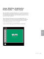
Conair Medline Combination Puller/Cutter - Touch panel . . . . . . . . . 4-5
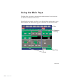
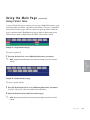
Using the main page . . . . . . . . . . . . . . . . . . . . . . . . . . . . . . . . . . . . 4-6
Using folder tabs . . . . . . . . . . . . . . . . . . . . . . . . . . . . . . . . . . 4-7
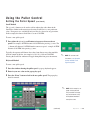
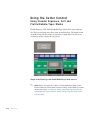
Using the puller control . . . . . . . . . . . . . . . . . . . . . . . . . . . . . . . . . . 4-8
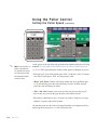
Setting the puller speed . . . . . . . . . . . . . . . . . . . . . . . . . . . . 4-8
Scroll method . . . . . . . . . . . . . . . . . . . . . . . . . . . . . . . 4-9
Keyboard method. . . . . . . . . . . . . . . . . . . . . . . . . . . . . 4-9
Using footage . . . . . . . . . . . . . . . . . . . . . . . . . . . . . . . . . . . 4-11
Using remote scrolling . . . . . . . . . . . . . . . . . . . . . . . . . . . . 4-11
Switched (local/remote) modes . . . . . . . . . . . . . . . . . . . . . . 4-12
Analog trim modes . . . . . . . . . . . . . . . . . . . . . . . . . . . . . . . 4-12
Storing the belt gap . . . . . . . . . . . . . . . . . . . . . . . . . . . . . . . . . . . 4-13
Using cutter control. . . . . . . . . . . . . . . . . . . . . . . . . . . . . . . . . . . . 4-14
Length . . . . . . . . . . . . . . . . . . . . . . . . . . . . . . . . . . . . . . . . 4-14
Setting cutter length . . . . . . . . . . . . . . . . . . . . . . . . . . . . . . 4-15
Using Encoder Sequence, Cuff and Profile/Bubble/Taper modes . . 4-18
Setting blade speed . . . . . . . . . . . . . . . . . . . . . . . . . . . . . . . . . . . 4-19
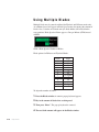
Using multiple blades . . . . . . . . . . . . . . . . . . . . . . . . . . . . . . . . . . 4-20
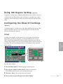
Using 180 degree cutting (optional). . . . . . . . . . . . . . . . . . . . . . . . 4-21
i i l Ta b l e o f C o n t e n t s
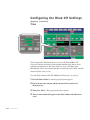
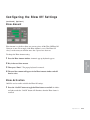
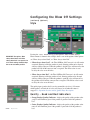
Configuring the blow off settings (optional) . . . . . . . . . . . . . . . . . . 4-21
Offset . . . . . . . . . . . . . . . . . . . . . . . . . . . . . . . . . . . . . . . . . 4-21
Time . . . . . . . . . . . . . . . . . . . . . . . . . . . . . . . . . . . . . . . . . 4-22
Blow amount. . . . . . . . . . . . . . . . . . . . . . . . . . . . . . . . . . . . 4-23
Blow activation . . . . . . . . . . . . . . . . . . . . . . . . . . . . . . . . . . 4-23
Style . . . . . . . . . . . . . . . . . . . . . . . . . . . . . . . . . . . . . . . . . 4-24
Good and bad indicators . . . . . . . . . . . . . . . . . . . . . . . . . . . 4-24
Scrap/Sort. . . . . . . . . . . . . . . . . . . . . . . . . . . . . . . . . . . . . . 4-25
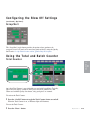
Using the total and batch counter . . . . . . . . . . . . . . . . . . . . . . . . . 4-25
Total counter . . . . . . . . . . . . . . . . . . . . . . . . . . . . . . . . . . . . 4-25
Batch counter . . . . . . . . . . . . . . . . . . . . . . . . . . . . . . . . . . . 4-26
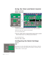
Configuring the batch settings. . . . . . . . . . . . . . . . . . . . . . . . . . . . 4-26
Set
. . . . . . . . . . . . . . . . . . . . . . . . . . . . . . . . . . . . . . . . . 4-26
Warn . . . . . . . . . . . . . . . . . . . . . . . . . . . . . . . . . . . . . . . . . 4-27
Pulse/Latch . . . . . . . . . . . . . . . . . . . . . . . . . . . . . . . . . . . . . 4-28
Alarm . . . . . . . . . . . . . . . . . . . . . . . . . . . . . . . . . . . . . . . . . 4-28
Accessing secured pages and presets . . . . . . . . . . . . . . . . . . . . . 4-29
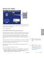
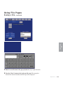
Using file pages . . . . . . . . . . . . . . . . . . . . . . . . . . . . . . . . . . . . . . 4-31
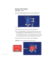
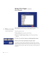
Opening a file . . . . . . . . . . . . . . . . . . . . . . . . . . . . . . . . . . . 4-32
Deleting a file . . . . . . . . . . . . . . . . . . . . . . . . . . . . . . . . . . . 4-33
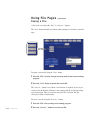
Saving a file . . . . . . . . . . . . . . . . . . . . . . . . . . . . . . . . . . . . 4-34
File contents . . . . . . . . . . . . . . . . . . . . . . . . . . . . . . . . . . . . . . . . . 4-36
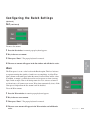
Configuring the network settings. . . . . . . . . . . . . . . . . . . . . . . . . . 4-37
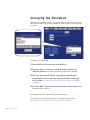
Changing the password. . . . . . . . . . . . . . . . . . . . . . . . . . . . . . . . . 4-38
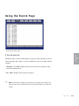
Using the events page. . . . . . . . . . . . . . . . . . . . . . . . . . . . . . . . . . 4-39
Using the faults page . . . . . . . . . . . . . . . . . . . . . . . . . . . . . . . . . . 4-40
Using the IO page . . . . . . . . . . . . . . . . . . . . . . . . . . . . . . . . . . . . . 4-41
Diagnostics character . . . . . . . . . . . . . . . . . . . . . . . . . . . . . 4-42
Debounce . . . . . . . . . . . . . . . . . . . . . . . . . . . . . . . . . . . . . . 4-43
Ta b l e o f C o n t e n t s l i i i
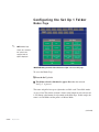
Configuring the set up 1 folder . . . . . . . . . . . . . . . . . . . . . . . . . . . 4-44
Modes page . . . . . . . . . . . . . . . . . . . . . . . . . . . . . . . . . . . . 4-44
Selecting modes . . . . . . . . . . . . . . . . . . . . . . . . . . . . . . . . . 4-46
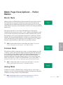
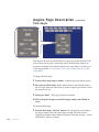
Mode page descriptions - Puller modes . . . . . . . . . . . . . . . . . . . . 4-47
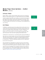
Mode page descriptions - Cutter modes . . . . . . . . . . . . . . . . . . . . 4-50
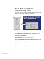
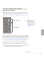
Scroll page descriptions . . . . . . . . . . . . . . . . . . . . . . . . . . . . . . . . 4-53
Cutter scrolls - Panel. . . . . . . . . . . . . . . . . . . . . . . . . . . . . . 4-53
Puller scrolls - Panel . . . . . . . . . . . . . . . . . . . . . . . . . . . . . . 4-55
Puller scrolls - Remote contacts . . . . . . . . . . . . . . . . . . . . . 4-56
Puller scrolls - Remote digital pot . . . . . . . . . . . . . . . . . . . . 4-58
Encoder page description . . . . . . . . . . . . . . . . . . . . . . . . . . . . . . . 4-60
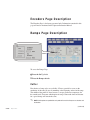
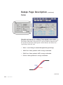
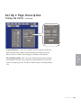
Ramps page description . . . . . . . . . . . . . . . . . . . . . . . . . . . . . . . . 4-60
Cutter . . . . . . . . . . . . . . . . . . . . . . . . . . . . . . . . . . . . . . . . . 4-60
Puller . . . . . . . . . . . . . . . . . . . . . . . . . . . . . . . . . . . . . . . . . 4-62
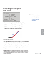
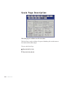
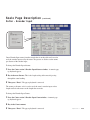
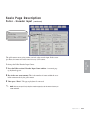
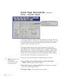
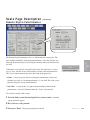
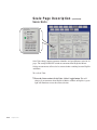
Scale page description . . . . . . . . . . . . . . . . . . . . . . . . . . . . . . . . . 4-64
Cutter - Encoder input. . . . . . . . . . . . . . . . . . . . . . . . . . . . . 4-65
Puller - Encoder input . . . . . . . . . . . . . . . . . . . . . . . . . . . . . 4-66
Puller - Encoder output . . . . . . . . . . . . . . . . . . . . . . . . . . . . 4-68
Puller - Belt scale . . . . . . . . . . . . . . . . . . . . . . . . . . . . . . . . 4-69
Maximum speed volts . . . . . . . . . . . . . . . . . . . . . . . . . . . . . 4-70
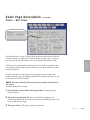
Analog input . . . . . . . . . . . . . . . . . . . . . . . . . . . . . . . . . . . . 4-73
Trim modes - Authority . . . . . . . . . . . . . . . . . . . . . . . . . . . . 4-74
Remote digital potentiometer . . . . . . . . . . . . . . . . . . . . . . . 4-75
Scale units . . . . . . . . . . . . . . . . . . . . . . . . . . . . . . . . . . . . . 4-76
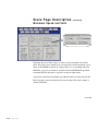
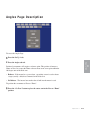
Angles page description . . . . . . . . . . . . . . . . . . . . . . . . . . . . . . . . 4-77
Park angle. . . . . . . . . . . . . . . . . . . . . . . . . . . . . . . . . . . . . . 4-78
Cut angle . . . . . . . . . . . . . . . . . . . . . . . . . . . . . . . . . . . . . . 4-79
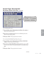
Set up 2 page description . . . . . . . . . . . . . . . . . . . . . . . . . . . . . . . 4-80
Tuning the belt drive . . . . . . . . . . . . . . . . . . . . . . . . . . . . . . 4-81
Tuning the cutter. . . . . . . . . . . . . . . . . . . . . . . . . . . . . . . . . 4-84
i v l Ta b l e o f C o n t e n t s
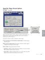
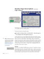
Quality page description . . . . . . . . . . . . . . . . . . . . . . . . . . . . . . . . 4-86
Offsets . . . . . . . . . . . . . . . . . . . . . . . . . . . . . . . . . . . . . . . . 4-86
Input polarity. . . . . . . . . . . . . . . . . . . . . . . . . . . . . . . . . . . . 4-88
When bad . . . . . . . . . . . . . . . . . . . . . . . . . . . . . . . . . . . . . . 4-89
Counters . . . . . . . . . . . . . . . . . . . . . . . . . . . . . . . . . . . . . . . 4-90
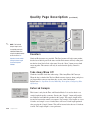
Take away/Blow off. . . . . . . . . . . . . . . . . . . . . . . . . . . . . . . . . . . . 4-90
Deferred sample . . . . . . . . . . . . . . . . . . . . . . . . . . . . . . . . . 4-90
Factory page description . . . . . . . . . . . . . . . . . . . . . . . . . . . . . . . . 4-91
About page . . . . . . . . . . . . . . . . . . . . . . . . . . . . . . . . . . . . . . . . . . 4-92
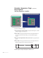
Encoder sequence page description . . . . . . . . . . . . . . . . . . . . . . . 4-93
Setting sequence lengths . . . . . . . . . . . . . . . . . . . . . . . . . . 4-94
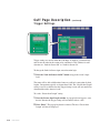
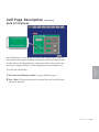
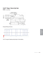
Cuff page description . . . . . . . . . . . . . . . . . . . . . . . . . . . . . . . . . . 4-95
Trigger setting. . . . . . . . . . . . . . . . . . . . . . . . . . . . . . . . . . . 4-96
Gate off distance. . . . . . . . . . . . . . . . . . . . . . . . . . . . . . . . . 4-97
Cuts . . . . . . . . . . . . . . . . . . . . . . . . . . . . . . . . . . . . . . . . . . 4-98
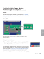
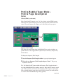
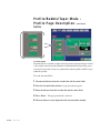
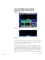
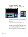
Profile/Bubble/Taper Modes - Profile page description . . . . . . . . 4-100
Puller . . . . . . . . . . . . . . . . . . . . . . . . . . . . . . . . . . . . . . . . 4-101
Velocity (FPM) . . . . . . . . . . . . . . . . . . . . . . . . . . . . . . . 4-102
Sequence length . . . . . . . . . . . . . . . . . . . . . . . . . . . . . 4-102
Cutter . . . . . . . . . . . . . . . . . . . . . . . . . . . . . . . . . . . . . . . . 4-104
Location offset . . . . . . . . . . . . . . . . . . . . . . . . . . . . . . 4-104
Additional cuts 1 and 2 . . . . . . . . . . . . . . . . . . . . . . . . 4-105
Body off cut . . . . . . . . . . . . . . . . . . . . . . . . . . . . . . . . 4-106
On line/ Off line. . . . . . . . . . . . . . . . . . . . . . . . . . . . . . 4-107
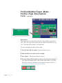
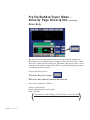
Profile/Bubble/Taper Modes - Velocity page description . . . . . . . 4-108
Index. . . . . . . . . . . . . . . . . . . . . . . . . . . . . . . . . . . . . . . . . 4-109
Ramp type . . . . . . . . . . . . . . . . . . . . . . . . . . . . . . . . . . . . 4-112
Key . . . . . . . . . . . . . . . . . . . . . . . . . . . . . . . . . . . . . . . . . . 4-113
Drive data . . . . . . . . . . . . . . . . . . . . . . . . . . . . . . . . . . . . . 4-114
Ratio calculator . . . . . . . . . . . . . . . . . . . . . . . . . . . . . . . . . 4-115
Ta b l e o f C o n t e n t s l v
Zoom . . . . . . . . . . . . . . . . . . . . . . . . . . . . . . . . . . . . . . . . 4-118
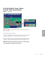
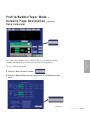
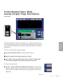
Profile/Bubble/Taper modes - Analog page description . . . . . . . . 4-119
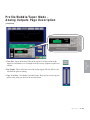
Profile/Bubble/Taper modes - Digital output page description . . . 4-124
Setting output length and duration . . . . . . . . . . . . . . . . . . 4-125
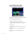
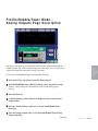
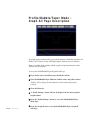
Profile/Bubble/Taper modes - Graph all page description . . . . . . 4-128
Profile/Bubble/Taper modes - Gauge control page description. . . 4-129
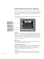
Cutter operator control features . . . . . . . . . . . . . . . . . . . . . . . . . 4-130
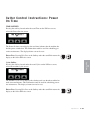
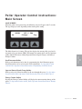
Cutter operator instructions main screen. . . . . . . . . . . . . . . . . . . 4-131
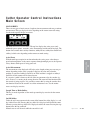
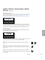
Cutter control instructions . . . . . . . . . . . . . . . . . . . . . . . . . . . . . . 4-132
Total screen . . . . . . . . . . . . . . . . . . . . . . . . . . . . . . . . . . . 4-132
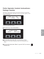
Batch screen. . . . . . . . . . . . . . . . . . . . . . . . . . . . . . . . . . . 4-134
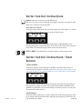
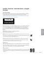
Length screen . . . . . . . . . . . . . . . . . . . . . . . . . . . . . . . . . . . . . . . 4-137
Preset to run screen . . . . . . . . . . . . . . . . . . . . . . . . . . . . . 4-138
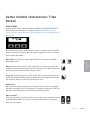
Time screen . . . . . . . . . . . . . . . . . . . . . . . . . . . . . . . . . . . 4-139
Hold-off screen . . . . . . . . . . . . . . . . . . . . . . . . . . . . . . . . . 4-140
Blade speed screen. . . . . . . . . . . . . . . . . . . . . . . . . . . . . . 4-141
Blade count screen . . . . . . . . . . . . . . . . . . . . . . . . . . . . . . 4-142
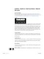
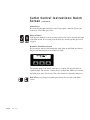
Cutter control instructions . . . . . . . . . . . . . . . . . . . . . . . . . . . . . . 4-143
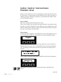
Functions areas. . . . . . . . . . . . . . . . . . . . . . . . . . . . . . . . . 4-143
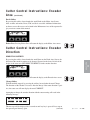
Test. . . . . . . . . . . . . . . . . . . . . . . . . . . . . . . . . . . . . . . . . . 4-144
Cut mode . . . . . . . . . . . . . . . . . . . . . . . . . . . . . . . . . . . . . 4-146
Minimum measurement . . . . . . . . . . . . . . . . . . . . . . . . . . 4-147
Maintenance area . . . . . . . . . . . . . . . . . . . . . . . . . . . . . . . 4-147
Encoder area. . . . . . . . . . . . . . . . . . . . . . . . . . . . . . . . . . . 4-148
Encoder direction . . . . . . . . . . . . . . . . . . . . . . . . . . . . . . . 4-149
Unit of measure . . . . . . . . . . . . . . . . . . . . . . . . . . . . . . . . 4-150
Scale distance. . . . . . . . . . . . . . . . . . . . . . . . . . . . . . . . . . 4-152
Scales counts . . . . . . . . . . . . . . . . . . . . . . . . . . . . . . . . . . 4-153
Homing . . . . . . . . . . . . . . . . . . . . . . . . . . . . . . . . . . . . . . . 4-154
v i l Ta b l e o f C o n t e n t s
Home offset . . . . . . . . . . . . . . . . . . . . . . . . . . . . . . . . . . . . . . . . 4-154
Offset example . . . . . . . . . . . . . . . . . . . . . . . . . . . . . . . . . . . . . . 4-156
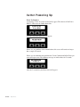
Power on time. . . . . . . . . . . . . . . . . . . . . . . . . . . . . . . . . . . . . . . 4-157
Cutter power up . . . . . . . . . . . . . . . . . . . . . . . . . . . . . . . . . . . . . . . . . . 4-158
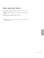
Puller operation control . . . . . . . . . . . . . . . . . . . . . . . . . . . . . . . . . . . . . 4-159
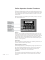
Puller operation control features . . . . . . . . . . . . . . . . . . . . . . . . . . . . . . 4-160
Puller operation control instructions . . . . . . . . . . . . . . . . . . . . . . . . . . . 4-161
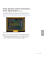
Main screen . . . . . . . . . . . . . . . . . . . . . . . . . . . . . . . . . . . . . . . . 4-161
Programming scroll increments. . . . . . . . . . . . . . . . . . . . . . . . . . 4-162
Using scroll increments. . . . . . . . . . . . . . . . . . . . . . . . . . . . . . . . 4-163
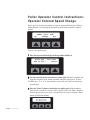
Operator entered speed change . . . . . . . . . . . . . . . . . . . . . . . . . 4-164
Footage counter . . . . . . . . . . . . . . . . . . . . . . . . . . . . . . . . . . . . . 4-165
Diagnostics screen . . . . . . . . . . . . . . . . . . . . . . . . . . . . . . . . . . . 4-166
Puller speed remote . . . . . . . . . . . . . . . . . . . . . . . . . . . . . . . . . . 4-167
Before starting the combination unit . . . . . . . . . . . . . . . . . . . . . . . . . . . 4-168
Start-up preparations for puller . . . . . . . . . . . . . . . . . . . . . . . . . . . . . . . 4-169
Powering up . . . . . . . . . . . . . . . . . . . . . . . . . . . . . . . . . . . . . . . . . . . . . 4-171
Programming the puller speed . . . . . . . . . . . . . . . . . . . . . . . . . . . . . . . 4-171
Starting the puller . . . . . . . . . . . . . . . . . . . . . . . . . . . . . . . . . . . . . . . . . 4-172
Stopping the puller . . . . . . . . . . . . . . . . . . . . . . . . . . . . . . . . . . . . . . . . 4-173
Shutting down the puller . . . . . . . . . . . . . . . . . . . . . . . . . . . . . . . . . . . . 4-173
Combination control features . . . . . . . . . . . . . . . . . . . . . . . . . . . . . . . . 4-173
Setting the scale factor . . . . . . . . . . . . . . . . . . . . . . . . . . . . . . . . . . . . . 4-174
Checking the cut quality . . . . . . . . . . . . . . . . . . . . . . . . . . . . . . . . . . . . 4-174
Setting the cutting mode - Two line HMI interface operation . . . . . . . . . 4-175
Making adjustments during operation for the cutter . . . . . . . . . . . . . . . 4-176
Stopping only the cutter . . . . . . . . . . . . . . . . . . . . . . . . . . . . . . . . . . . . 4-177
Stopping the Combination Puller/Cutter. . . . . . . . . . . . . . . . . . . . . . . . . 4-178
Shutting down the Combination Puller/Cutter . . . . . . . . . . . . . . . . . . . . 4-178
Ta b l e o f C o n t e n t s l v i i
5-1 M a i n t e n a n c e
Maintenance features . . . . . . . . . . . . . . . . . . . . . . . . . . . . . . . . . . . 5-2
Warnings and cautions . . . . . . . . . . . . . . . . . . . . . . . . . . . . . . . . . . 5-2
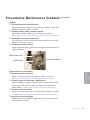
Preventative maintenance schedule . . . . . . . . . . . . . . . . . . . . . . . . 5-4
Inspecting cutter blades . . . . . . . . . . . . . . . . . . . . . . . . . . . . . . . . . 5-6
Inspecting blade hardware . . . . . . . . . . . . . . . . . . . . . . . . . . . . . . . 5-6
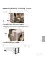
Inspecting cutter bushing retaining system . . . . . . . . . . . . . . . . . . . 5-7
Checking the closure latch . . . . . . . . . . . . . . . . . . . . . . . . . . . . . . . 5-7
Checking floor locks . . . . . . . . . . . . . . . . . . . . . . . . . . . . . . . . . . . . 5-7
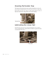
Cleaning the particulate trap . . . . . . . . . . . . . . . . . . . . . . . . . . . . . . 5-8
Lubricating the linear rail . . . . . . . . . . . . . . . . . . . . . . . . . . . . . . . . 5-8
Checking grease locations . . . . . . . . . . . . . . . . . . . . . . . . . . . . . . . 5-9
For puller model 1-12 . . . . . . . . . . . . . . . . . . . . . . . . . . . . . . 5-9
Lubricating shaft and fittings . . . . . . . . . . . . . . . . . . . . . . . . . . . . . 5-9
For puller model 3-20 . . . . . . . . . . . . . . . . . . . . . . . . . . . . . . 5-9
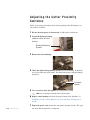
Adjusting the cutter proximity switches. . . . . . . . . . . . . . . . . . . . . 5-10
Checking electrical connections . . . . . . . . . . . . . . . . . . . . . . . . . . 5-11
Testing belt tension . . . . . . . . . . . . . . . . . . . . . . . . . . . . . . . . . . . . 5-13
Checking the belt gap . . . . . . . . . . . . . . . . . . . . . . . . . . . . . . . . . . 5-15
For puller model 1-12 . . . . . . . . . . . . . . . . . . . . . . . . . . . . . 5-15
For puller model 3-20 . . . . . . . . . . . . . . . . . . . . . . . . . . . . . 5-15
Replacing belts . . . . . . . . . . . . . . . . . . . . . . . . . . . . . . . . . . . . . . . 5-16
For puller model 1-12 . . . . . . . . . . . . . . . . . . . . . . . . . . . . . 5-16
For puller model 3-20 . . . . . . . . . . . . . . . . . . . . . . . . . . . . . 5-17
Checking torque . . . . . . . . . . . . . . . . . . . . . . . . . . . . . . . . . 5-19
v i i i l Ta b l e o f C o n t e n t s
6-1 Tr o u b l e s h o o t i n g
Before beginning. . . . . . . . . . . . . . . . . . . . . . . . . . . . . . . . . . . . . . . 6-2
A few words of caution . . . . . . . . . . . . . . . . . . . . . . . . . . . . . . . . . . 6-2
Identify the cause of a problem. . . . . . . . . . . . . . . . . . . . . . . . . . . . 6-4
Puller operation problems . . . . . . . . . . . . . . . . . . . . . . . . . . . . . . . . 6-5
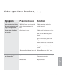
Cutter operation problems. . . . . . . . . . . . . . . . . . . . . . . . . . . . . . . . 6-6
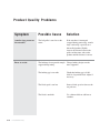
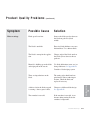
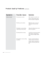
Product quality problems. . . . . . . . . . . . . . . . . . . . . . . . . . . . . . . . 6-10
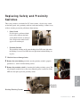
Replacing safety and proximity switches. . . . . . . . . . . . . . . . . . . . 6-15
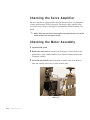
Checking the servo amplifier. . . . . . . . . . . . . . . . . . . . . . . . . . . . . 6-16
Checking the motor assembly . . . . . . . . . . . . . . . . . . . . . . . . . . . . 6-16
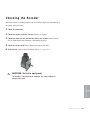
Checking the encoder . . . . . . . . . . . . . . . . . . . . . . . . . . . . . . . . . . 6-17
Testing repeatability . . . . . . . . . . . . . . . . . . . . . . . . . . . . . . . . . . . 6-18
Results of repeatability testing . . . . . . . . . . . . . . . . . . . . . . . . . . . 6-19
A
Appendix
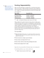
We’re here to help . . . . . . . . . . . . . . . . . . . . . . . . . . . . . . . . . . . . . A-1
Customer service information . . . . . . . . . . . . . . . . . . . . . . . . . . . . . A-1
Warranty information. . . . . . . . . . . . . . . . . . . . . . . . . . . . . . . . . . . . A-2
B
Appendix
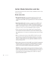
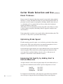
Cutter blade selection and use . . . . . . . . . . . . . . . . . . . . . . . . . . . . B-1
Cutting tips . . . . . . . . . . . . . . . . . . . . . . . . . . . . . . . . . . . . . . . . . . . B-3
Calculating blade interruption . . . . . . . . . . . . . . . . . . . . . . . . . . . . . B-4
Conair cutter blades . . . . . . . . . . . . . . . . . . . . . . . . . . . . . . . . . . . . B-6
C
Appendix
All about cutter bushings . . . . . . . . . . . . . . . . . . . . . . . . . . . . . . . . C-1
D
Appendix
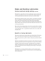
Blade and bushing lubrication. . . . . . . . . . . . . . . . . . . . . . . . . . . . . D-1
Ta b l e o f C o n t e n t s l i x
E
Appendix
Choosing belt materials. . . . . . . . . . . . . . . . . . . . . . . . . . . . . . . . . . E-1
Conair belts. . . . . . . . . . . . . . . . . . . . . . . . . . . . . . . . . . . . . . . . . . . E-1
F
Appendix
Using the digital belt gap sensor . . . . . . . . . . . . . . . . . . . . . . . . . . . F-1
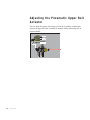
Adjusting the pneumatic upper belt actuator . . . . . . . . . . . . . . . . . . F-2
x l Ta b l e o f C o n t e n t s
SECTION
1
Purpose of the user guide . . . . . . . . . . . . . . 1-2
How the guide is organized . . . . . . . . . . . . . 1-2
Yo u r r e s p o n s i b i l i t i e s a s a u s e r . . . . . . . . . . . 1 - 2
AT T E N T I O N :
Read this so no one gets hurt . . . . . . . . 1-3
How to use the lockout device . . . . . . . . . . . 1-5
Introduction l 1-1
1
Introduction
Introduction
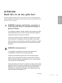
Purpose of the User Guide
This User Guide describes the Conair Medline Combination Puller/Cutter
and explains step-by-step how to install, operate, maintain and repair this
equipment.
Before installing this product, please take a few moments to read the
User Guide and review the diagrams and safety information in the
instruction packet. You also should review manuals covering associated
equipment in your system. This review won’t take long, and it could save
you valuable installation and operating time later.
How the Guide is Organized
Symbols have been used to help organize the User Guide and call your
attention to important information regarding safe installation and operation.
Symbols within triangles warn of conditions that could be hazardous to users or
could damage equipment. Read and take precautions before proceeding.
1
Numbers indicate tasks or steps to be performed by the user.
u
A diamond indicates the equipment’s response to an action performed by the user.
r
An open box marks items in a checklist.
•
A circle marks items in a list.
2
0
Indicates a tip. A tip is used to provide you with a suggestion that will help you with
the maintenance and operation of this equipment.
Indicates a note. A note is used to provide additional information about the steps
you are following throughout this manual.
Yo u r R e s p o n s i b i l i t y a s a U s e r
You must be familiar with all safety procedures concerning installation, operation and maintenance of this equipment. Responsible safety
procedures include:
•
•
1-2 l Introduction
•
•
Thorough review of this User Guide, paying particular attention
to hazard warnings, appendices and related diagrams.
Thorough review of the equipment itself, with careful attention
to voltage sources, intended use and warning labels.
Thorough review of instruction manuals for associated equipment.
Step-by-step adherence to instructions outlined in this User Guide.
AT T E N T I O N :
Read this so no one gets hurt
WA R N I N G : I m p r o p e r i n s t a l l a t i o n , o p e r a t i o n o r
servicing may result in equipment damage or
p e r s o n a l i n j u r y.
This equipment should be installed, adjusted, and serviced by qualified
technical personnel who are familiar with the construction, operation
and potential hazards of this type of machine.
All wiring, disconnects and fuses should be installed by qualified electrical technicians in accordance with electrical codes in your region.
Always maintain a safe ground. Do not operate the equipment at power
levels other than what is specified on the the machine serial tag and
data plate.
WA R N I N G : Vo l t a g e h a z a r d
This equipment is powered by three-phase alternating current,
as specified on the machine serial tag and data plate.
A properly sized conductive ground wire from the incoming power
supply must be connected to the chassis ground terminal inside the
electrical enclosure. Improper grounding can result in severe personal
injury and erratic machine operation.
Always disconnect and lock out the incoming main power source before
opening the electrical enclosure or performing non-standard operating
procedures, such as routine maintenance. Only qualified personnel
should perform troubleshooting procedures that require access to the
electrical enclosure while power is on.
(continued)
Introduction l 1-3
1
Introduction
We design equipment with the user’s safety in mind. You can avoid the potential
hazards identified on this machine by following the procedures outlined below and
elsewhere in the User Guide.
AT T E N T I O N :
Read this so no one gets hurt
(continued)
We design equipment with the user’s safety in mind. You can avoid the potential
hazards identified on this machine by following the procedures outlined below and
elsewhere in the User Guide.
WA R N I N G : P i n c h h a z a r d
Never remove or disable safety devices to sustain production. Operating
without these devices could lead to hazardous conditions that can cause
severe injury.
1-4 l Introduction
•
Walk-through style belt guards which protect from injury, but also, allow
side entry for ease of operation. Upper and lower belt guards independently protect the operator from being caught in the belts or associated
driven sheaves (sprockets).
•
The power cord is attached to the upper guard by a receptacle on the
rear side of the guard. You must disconnect this power cord to remove
the upper belt guard, ensuring that the puller will not start if the upper
guard is not in place.
•
The flip up safety switch on the discharge end of the upper belt guard
allows operation only when in the down position. If a finger or piece of
clothing is caught on the upper belt and drawn in, the guard flips up and
immediately shuts off the power to the entire combination puller/cutter.
•
The “Emergency Stop” button is located on the control panel and on top of
the upper belt guard at the upstream end. Pressing either of these buttons
disconnects power to the entire unit. The “Emergency Stop” must be physically pulled up to reset the switch and start the combination puller/cutter
again.
•
When the knife guard is opened, the knife guard switch stops the cutter.
•
Two proximity safety switches prevent cutter operation unless the cutter
bushings are in place.
•
The “Stop” button on the puller and cutter controls activates a circuit that
stops the puller and cutter knife.
How to Use the Lockout Device
CAUTION: Before performing maintenance or repairs on this product, you should
disconnect and lockout electrical power sources to prevent injury from unexpected
energization or start-up. A lockable device has been provided to isolate this product from potentially hazardous electricity.
Lockout is the preferred method of isolating machines or equipment from energy
sources. Your Conair product is equipped with the lockout device pictured below.
To use the lockout device:
1 Stop or turn off the equipment.
2 Isolate the equipment from the electric power. Turn the rotary
disconnect switch to the OFF, or “O” position.
3 Secure the device with an assigned lock or tag. Insert a lock or tag
in the holes to prevent movement.
4 The equipment is now locked out.
WARNING: Before removing lockout devices and returning switches to the ON
position, make sure that all personnel are clear of the machine, tools have
been removed, and all safety guards reinstalled.
To restore power to the dryer, turn the rotary disconnect back to the ON position:
1 Remove the lock or tag.
2 Turn the rotary disconnect switch to the ON or “I” position.
Introduction l 1-5
1-6 l Introduction
SECTION
2
What is the Medical Combination
Puller/Cutter? . . . . . . . . . . . . . . . . . . .2-2
Ty p i c a l a p p l i c a t i o n s . . . . . . . . . . . . . . . . . . 2 - 2
Limitations . . . . . . . . . . . . . . . . . . . . . . . . 2-3
How the Combination Puller/Cutter works . . . 2-4
Specifications: Medline Combination
Puller/Cutter . . . . . . . . . . . . . . . . . . . 2-7
Puller optional equipment . . . . . . . . . . . . . . 2-9
Cutter optional equipment. . . . . . . . . . . . . . 2-9
Common optional equipment . . . . . . . . . . . 2-10
Description l 2-1
2
Description
Description
What is the Medical Combination
Puller/Cutter?
The Conair Medline Combination Puller/Cutter pulls small extruded tubing
through sizing and/or cooling tanks and cuts the product to lengths. Since the
puller and cutter are mounted on the same chassis, alignment problems are minimized.
The puller portion's dual servo drive system offers extremely accurate speed
control. Different puller belt materials optimize performance with different types
of extruded materials, or applications.
The cutter portion utilizes a position-controlled servo motor. CSC units achieve
park position repeatability less than 0.1 millisecond.
Ty p i c a l A p p l i c a t i o n s
Conair Medical Combination Puller/Cutters process extrudable plastics on-line.
While the standard orientation is right-to-left, combination puller/cutters can
also be made with a left-to-right orientation. See Description Section entitled,
Specifications: Medline Combination Puller/Cutter. (The illustrations in this
User Guide represent the standard right-to left configuration.)
CSC cutters are limited to a specific range of product sizes based on each unit's
cutting capacity. CSC cutters can operate over a range of speeds (depending on
which options are included.) See Description Section entitled, Specifications:
Medline Combination Puller/Cutter.
Profile/Bubble/Taper tubing can be processed with the optional touchscreen and
Profile/Bubble/Taper software. With this option, it is recommended to use
sponge belts.
2-2 l Description
Limitations
•
The unit is limited by the traction length (the length over which the
extrudate is in contact with the puller belts), which is fixed for particular models.
•
The outer surface of the puller belt material will affect performance.
Softer (low durometer) materials provide good “grab”, but will wear
more quickly, and may tear if the belt jams. Harder (high durometer)
materials last longer, but may not grab the extrudate properly.
Contact Conair for specific belt material recommendations for your product.
Description l 2-3
2
Because the maximum distance between the puller and cutter is only 6
inches {152.4 mm}, the combination puller/cutter is not suitable for
larger rigid extruded parts.
Description
•
How the Combination Puller/Cutter
Wo r k s
First, the extruded material that has been sized and cooled enters the combination
puller/cutter from the upstream side. The extrudate passes through and is positioned by guide rollers.
Then, the two opposing belts move the extrudate through the puller. These belts
have grooves that fit teeth on the puller’s sheaves (sprockets), preventing side-toside movement. Belt coverings are available in a variety of materials for specific
applications. Walk-through style belt guards ensure operator safety while allowing
access to the belts. The belt speed is controlled by eye-level controls.
A threaded rod controls the distance between the upper and lower belts. The top
and bottom belts open from a common, fixed center. Rubber grommets, on the
CPC 1-12, allow the upper belt to 'give' slightly, preventing the puller from being
damaged by small lumps of extrudate or other foreign objects.
After passing through the belts, the extrudated material continues on to the cutter.
The cutter is mounted on linear slides that allow as much as 6 inches {152.4 mm}
of movement. The cutter can be moved away from the puller for startup, then
moved close to the puller to enhance delivery to the cutter bushings.
Next, the cutter's servo motor, which is positionally controlled, operates the cutter
head and knife that is attached directly to the servo motor using a Trantorque
coupling device. Two cutter bushings guide and support both the extrudate and
the cutting knife. The extrudate passes through the cutter bushings and is cut by
the rotating cutter head.
The cut pieces are collected or carried on to further processing by an optional
conveyor. (Take Away/Blow Off Conveyor)
(continued)
2-4 l Description
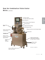
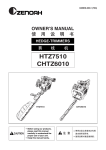
How the Combination Puller/Cutter
Wo r k s ( c o n t i n u e d )
Clear knife guard
Digital belt gap read-out (Optional)
Belt adjustment
Servo cutter
motor
Cutter head with blade(s)
Emergency Stop
Material inlet through
cutter bushings
Belt guard (with clear walk-through design)
Guide rollers
Particulate
collection tray
Optional mister
for bushing and
tube lubrication
Puller belts
(FDA)
PD series
Optional stainless steel
stand (shown). White painted carbon steel is standard.
Stainless steel
level screw
Model CPC-1-12/CSC-0.25
Urethane (FDA) stainless
steel swivel casters
Description l 2-5
2
Description
Eye-level controls
10” touchscreen option (shown)
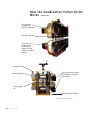
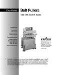
How the Combination Puller/Cutter
Wo r k s ( c o n t i n u e d )
PD series selftracking FDA
sheaves (sprockets)
Precision idler rolls
Puller belt
50 Duro white
(FDA) natural
rubber or white
(FDA) closed face
sponge
Emergency Stop
Grease fittings (4)
Dual servo puller motors
with precision planetary
gearheads
Product guide
roll
Digital belt gap (Optional)
CPC-1-12 puller model shown
2-6 l Description
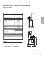
Specifications: Medline Combination
Puller/Cutter
MODELS
Performance characteristics
Extrudate capacity in. {mm} dia.
Blade drive motor (3000 rpm)
CSC cutter Hp {kW}
Electrical requirements Full Load Amps
Drive type(Puller)
230V/3 phase/60Hz
460V/3 phase/60Hz
Cutter Control
2.46 {1.83}
(2) 0.43 {0.32}
A
71.0 {1803.4}
42.0 {1067}
40.0 {1016}
27.0 {685.8}
1.0 {25.4}
12.0 {304.8}
2.0 {50.8}
715 {324}
800 {363}
D
Dual Servo with
precision planetary gearhead
(2) 0.43 Hp
20
12
Red Lion
SPECIFICATION NOTES
Specifications may change without notice. Check with a Conair representative for the most current information.
TPES016-1206-REV
B
OPTIONS
• 10 inch touchscreen • Profile/Bubble/Taper
control (in place of
software
standard 6 inch screen)
• Stainless steel cabinet • Digital gap readout
C
(continued)
Description l 2-7
2
Weight lb {kg}
Installed
Shipping
0.25 {6.35}
Description
Servo puller drive motor Hp {kW}
Dimensions in. {mm}
A - Height
B - Height to centerline, ±2 {±50.8}
C - Width
D - Depth
Belt width ±3/8 {±9.5}
Belt traction length
Feed opening
CPC-1-12/CSC-0.25L
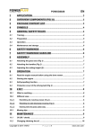
Specifications: Medline Combination
P u l l e r / C u t t e r (continued)
MODELS
Performance characteristics
Extrudate capacity in. {mm} dia.
Blade drive motor (3000 rpm)
CSC cutter Hp {kW}
Puller drive motor Hp {kW}
Optional Servo drive motor Hp {kW}
Dimensions in. {mm}
A - Height
B - Height to centerline, ±2 {±50.8}
C - Width
D - Depth
Belt width ±3/8 {±9.5}
Belt traction length
A
Feed opening
Weight lb {kg}
Installed
D
Cutter
Off On
Manual
Cut
Power On
Cutter
Stop
Cutter
Start
EMERGENCY
Puller
Stop
CPC-3-20/CSC-0.25L
0.25 {6.35}
2.7 {2.01}
1 (0.75}
2.46 {1.83}
71.0 {1803.4}
42.0 {1067}
45.0 {1143}
27.0 {685.8}
3.0 {76.2}
20.0 {508}
4.0 {102}
735 {333}
Shipping
820 {372}
Electrical requirements Full Load Amps
Drive type(Puller)
Closed Loop
Servo
1.0 Hp
2.46Hp
230V/3 phase/60Hz
19.7
33.6
460V/3 phase/60Hz
10.5
16.8
Cutter Control
Red Lion
Puller
Start
STOP
SPECIFICATION NOTES
Specifications may change without notice. Check with a Conair representative for the most current information.
TPES016-1206-REV
OPTIONS
B
• Servo drive motor
C
2-8 l Description
• Stainless steel cabinet
Puller Optional Equipment
• Digital belt gap sensor and readout - (Optional) Allows the operator to set a
zero point, then measure belt gap (in thousandths of an inch) relative to this
setpoint.
• Remote belt speed control - (Optional) Allows the puller speed to be controlled
by an external source. (Remote Digital Potentiometer)
the time of purchase to optimize puller performance in a particular speed range.
Contact a Conair Representative for application specific gear reducers
Cutter Optional Equipment
• Cutter bushing lubrication - (Optional) A self-contained spray system, which
includes a reservoir and an air inlet for operation at 20-30 psi (air source not
included). A flexible nozzle directs lubricant onto the extrudate as it enters the
cutter bushings. This decreases bushing drag and helps lubricate the blade. This
option is recommended for processing sticky/soft (low durometer) materials.
• Cutter blade wipe - (Optional) Keeps the cutting blade clean by removing
lubricant and particles. A reservoir chamber with a flexible drip tube feeds
lubricant to a felt pad sandwiched between two pieces of stainless steel in the
particulate tray. The pad wipes and lubricates the knife before each cut.
• Profile/Bubble/ Taper software upgrade package - The standard serial operator
interface units are replaced with a common color touchscreen operator interface.
A positional control unit is added to the puller servo drive, along with a PLC
(Programmable Logic Controller) enabling positional moves needed for
Profile/Bubble/Taper tubing processing. Basic output package enables operation
for up to two lumens with 32 points of analog outputs each. Specialized software for processing Profile/Bubble/Taper tubing includes: up to 32 preset positional moves for input speed and distance, 24 VDC output for blow off, four digital
powered outputs - 24 VDC transistorized 0.25 amps each and two 0 to 10 VDC
analog outputs.
• Main cabinet housing - (Optional) Stainless steel in place of standard white
painted carbon steel cabinet.
(continued)
Description l 2-9
2
Description
• In-line planetary gear reducer ratios - A particular reducer ratio is selected at
Cutter Optional Equipment
(continued)
• Follower cutting Mode - Follower Mode allows the operator to program the
desired cut length and the number of blades. The controller then automatically
follows the puller and adjusts the speed of the flywheel to maintain cut length
accuracy. This is known as an electronic gear lock system. The cut length accuracy is maintained even if the puller changes speed.
Common Optional Equipment
• Discharge conveyor - A discharge conveyor offers support before, during, and
after cutting, and facilitates the removal of cut parts. Discharge conveyors are
available in the following sizes:
• 6 inches wide by 6 feet long
• 6 inches wide by 12 feet long
• 6 inches wide by 16 feet long
• Isolation Transformer - The isolation transformer protects sensitive electronics
from incoming power, which helps prevent errors caused by electrical noise. It
also protects equipment from electrical noise generated by the servo motor and
associated amplifiers.
0
0
NOTE: Conair strongly recommends using an isolation transformer. Ensuring clean and proper
power can help avoid the need for costly service calls.
NOTE: An isolation transformer will not compensate for a ground that does not meet code
requirements.
• Left-to-Right machine operation - This option changes the machine direction .
from the standard right-to-left extrusion flow to left-to-right.
Your Conair sales representative can analyze your needs and recommend the
options that are right for your system.
2-10 l Description
SECTION
3
Installation
Unpacking the boxes . . . . . . . . . . . . . . . . . 3-2
Preparing for installation . . . . . . . . . . . . . . 3-3
Po s i t i o n i n g t h e C o m b i n a t i o n P u l l e r / C u t t e r . . . 3 - 4
Installing the cutter blades . . . . . . . . . . . . 3-7
Mounting the cutter bushings . . . . . . . . . . . 3-8
Adjusting belt tension . . . . . . . . . . . . . . . 3-10
Fo r p u l l e r m o d e l 1 - 1 2 . . . . . . . . . . . . . 3 - 1 0
Fo r p u l l e r m o d e l 3 - 2 0 . . . . . . . . . . . . . 3 - 1 1
Setting the belt gap . . . . . . . . . . . . . . . . . 3-13
Fo r p u l l e r m o d e l 1 - 1 2 . . . . . . . . . . . . . 3 - 1 3
Fo r p u l l e r m o d e l 3 - 3 0 . . . . . . . . . . . . . 3 - 1 3
Checking repeatability . . . . . . . . . . . . . . . 3-14
Repea tability t e s t r e s u l t s . . . . . . . . . . . . . . 3 - 1 5
Preparing for testing . . . . . . . . . . . . . . . . 3-16
Te s t i n g t h e i n s t a l l a t i o n . . . . . . . . . . . . . . . 3 - 1 7
Tw o L i n e H M I i n t e r f a c e o p e r a t i o n . . . . . 3 - 1 7
To u c h s c r e e n H M I i n t e r f a c e o p e r a t i o n . . . 3 - 1 8
Installation l 3-1
3
Installation
Connecting the main power source . . . . . . . . 3-6
Unpacking the Boxes
The Conair Medline Combination Puller/Cutter comes fully assembled in a single
crate.
CA U T I O N : L i f t i n g
To avoid personal injury or damage to the puller/cutter, lift the puller/ cutter
using a forklift or hoist with straps that have been positioned at the
puller/cutter’s center of gravity.
To uncrate the Medline Combination Puller/Cutter:
1 Carefully uncrate the puller/cutter and its components.
2 Remove all packing material, protective paper, tape, and plastic. Compare
contents to the shipping papers to ensure that you have all the parts.
3 Carefully inspect all components to make sure no damage occurred during
shipping. Check all wire terminal connections, bolts, and any other electrical
connections, which may have come loose during shipping.
4 Record serial numbers and specifications in the blanks provided on the back
of the User Guide's title page. This information will be helpful if you ever need
service or parts.
5 You are now ready to begin installation. See Installation Section entitled,
Preparing for Installation.
3-2 l Installation
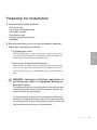
Preparing for Installation
1 You will need these tools for installation:
r wire strain relief
r 16 or 18 inch adjustable wrench
r set of Allen wrenches
r set of Feeler gauges
r 1/2 inch open or box end wrench
r flashlight.
2 Plan the location. Make sure the area where the Medline Combination
Puller/Cutter is installed has the following:
r Clearance for safe operation and maintenance.
Make sure there is enough clearance around the servo cutter for maintenance and servicing. If the cutter portion has the optional slide base, be
sure to check for clearance by extending the slide system in both directions.
WA R N I N G : I m p r o p e r i n s t a l l a t i o n , o p e r a t i o n , o r
servicing may result in equipment damage or
p e r s o n a l i n j u r y.
This equipment should only be installed, adjusted, and serviced by qualified
technical personnel who are familiar with the construction, operation, and
potential hazards of this type of machine.
All wiring, disconnects, and fuses should be installed by qualified electrical
technicians in accordance with electrical codes in your region. Always maintain a safe ground. Do not operate the equipment at power levels other than
what is specified on the machine serial tag and data plate.
Installation l 3-3
3
Installation
r A grounded power source.
Check the puller/cutter’s serial tag for the correct amps, voltage, phase
and cycles. All wiring should be completed by qualified personnel and
should comply with your region’s electrical codes.
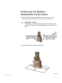
Po s i t i o n i n g t h e M e d l i n e
Combination Puller/Cutter
1 Move the Medline Combination Puller/Cutter into position. Place the
puller/cutter in position downstream of the last sizing or cooling tank.
CA U T I O N : L i f t i n g
To avoid personal injury or damage to the cutter, lift the cutter using a forklift or hoist with straps that have been positioned at the combo’s center of
gravity.
2 Align the puller/cutter with the extrusion line.
(continued)
3-4l Installation
Po s i t i o n i n g t h e M e d l i n e
Combination Puller/Cutter
(continued)
3 Measure the centerline height of the extrudate as it exits the extrusion die.
Adjust all equipment on the extrusion line (sizing tank, cooling tanks,
puller/cutter) to this height.
4 Adjust the puller/cutter's floor lock/caster assembly to the center height of
the extrusion line using a 16 or 18-inch adjustable wrench. Remove the weight
from the casters by locking down the floor locks.
IMPORTANT: Never leave the puller/cutter on casters only.
through each line component to the cutter bushings. Adjust as necessary.
6 Adjust the belt puller entrance guide rollers to insure consistent product
guidance.
Installation l 3-5
3
Installation
5 Use a plumb line or laser to check for a straight line from the extrusion die
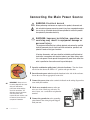
C o n n e c t i n g t h e M a i n Po w e r S o u r c e
WA R N I N G : E l e c t r i c a l h a z a r d
Before performing maintenance or repairs on this product, disconnect and
lock out electrical power sources to prevent injury from unexpected energization or start-up. A lockable device has been provided to isolate this product
from potentially hazardous electricity.
WA R N I N G : I m p r o p e r i n s t a l l a t i o n , o p e r a t i o n , o r
servicing may result in equipment damage or
p e r s o n a l i n j u r y.
This equipment should only be installed, adjusted, and serviced by qualified
technical personnel who are familiar with the construction, operation, and
potential hazards of this type of machine.
All wiring, disconnects, and fuses should be installed by qualified electrical
technicians in accordance with electrical codes in your region. Always maintain a safe ground. Do not operate the equipment at power levels other than
what is specified on the machine serial tag and data plate.
1 Open the combination puller/cutter’s electrical enclosure. Turn the disconnect dial on the door to the OFF or “O” position and open the door.
2 Insert the main power wire through the knockout in the side of the enclosure.
Secure the wire with an appropriate strain relief.
3 Connect the power wires to the terminals indicated on the wiring diagram that
2
IMPORTANT: Always refer to
the wiring diagrams that came
with your combination
puller/cutter before making
electrical connections. The
diagrams show the minimum
size main power cable
required for your machine, and
the most accurate electrical
component information.
3-6 l Installation
came with your machine.
4 Check every terminal screw to make sure
wires are secure. Gently tug each wire. If a
wire is loose, use a screwdriver to tighten the
terminal.
5 Connect the ground wire to the grounding
point shown in the wiring diagram shipped
with your unit.
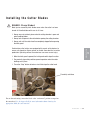
Installing the Cutter Blades
DA N G E R : S h a r p B l a d e s !
Most injuries caused by knife blades occur when the cutter has been
turned off. Handle blades with care at all times.
•
•
•
Always wear cut-resistant gloves when the cutting chamber is open and
when handling blades.
Always lock out power to the cutter before opening the cutting chamber.
Always wait until the cutter head has completely stopped before opening
the knife guard.
•
When the knife guard is opened, the knife guard switch stops the cutter.
Two proximity-type safety switches prevent operation unless the cutter
bushings are in place.
The cutter “Stop” button activates a circuit that stops the cutter head.
Proximity switches
For on-demand cutting, mount the blade at the “on-demand” position stamped on
the cutter head. See the Appendix B, for more information about choosing the
appropriate blade for your material.
Installation l 3-7
3
•
•
Installation
Combination puller/cutters are equipped with several safety devices to
ensure safe operation. Never remove or disable these devices to sustain
production. Operating without these devices can cause severe injury.
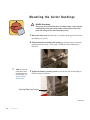
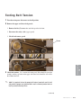
Mounting the Cutter Bushings
DANGER: Sharp blades
Always wear cut-resistant gloves when the cutting chamber is open and when
handling blades. Never open cutting chamber without locking out the cutter
power and waiting until the cutter head stops spinning.
1 Rotate the cutter head until the blade is positioned in the gap between where
the bushings are located.
2 Slide the downstream bushing into position, positioning it up to and barely
touching the blade (using a feeler gauge). NOTE: the blade should not be
deflected.
0
NOTE: For more information about setting
and adjusting the gap
for the bushings, see
Appendix C, About
Cutter Bushings
3 Tighten the bushing retaining system against the flat side of the bushing to
hold the bushing in position.
Bushing Retaining System
(continued)
3-8 l Installation
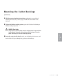
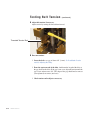
Mounting the Cutter Bushings
(continued)
4 Slide the upstream bushing into position, positioning it up to and barely
touching the blade (using a feeler gauge). NOTE: the blade should not be
deflected.
5 Tighten the bushing retaining system against the flat side of the bushing to
hold the bushing in position.
6 Rotate the cutter head by hand to make sure the bushings did not move, and
that the blade still passes through the gap between the bushings.
Installation l 3-9
3
Installation
DANGER: Sharp blades
Always wear cut-resistant gloves when the cutting chamber is open and when
handling blades. Never open cutting chamber without locking out the cutter
power and waiting until the cutter head stops spinning.
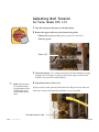
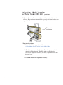
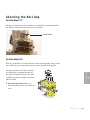
A d j u s t i n g B e l t Te n s i o n
For Puller Model CPC 1-12
1 Turn the main power disconnect to the off position.
2 Remove the upper and lower polycarbonate belt guards:
• Remove the screws attaching guards to unit (five each: front).
• Remove guards.
Screw (10)
3 Check belt tension. Use a tension-measuring tool. Belts should be just tight
enough to prevent slipping, and the gap between the upper and lower belts
should be even across the width of the belt.
0
NOTE: Loose belts result in
belt and product slippage;
over-tightened belts result in
distorted product and can
lead to premature bearing
failure.
4 Adjust belt tension, if necessary.
Adjust tension by turning the threaded tension rods. Keep tension on front and
back edges, the top and bottom belts should be as even as possible.
Threaded tension rods
3-10 l Installation
(continued)
A d j u s t i n g B e l t Te n s i o n
For Puller Model CPC 1-12
(continued)
5 Fine tune tension:
• Lower the belts to a gap of about 1/8 inch (3 mm).
See Installation Section entitled, Setting the Belt Gap.
• From the upstream end of the belts, look down the length of the belts at
the gap between the belts. If the gap is not even, adjust the tension until
the gap is even and measures 1/8 inch. The shape of the gap should not be
concave (over-tightened) or convex (too loose).
•
Check tension and re-adjust as necessary.
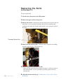
1 Turn the main power disconnect to the off position.
2 Remove the belt guards. Remove the screws attaching guards to unit (four on
each guard: top, bottom, front and rear). Disconnect the safety cable on the
upper guard. Lift off and remove guard.
3 Check belt tension. Use a tension-measuring tool. Belts should be just tight
enough to prevent slipping, and the gap between the upper and lower belts
should be even across the width of the belt.
0
NOTE: Loose belts result in belt and product slippage; over-tightened belts result in distorted
product and can lead to premature bearing failure.
(continued)
Installation l 3-11
3
Installation
For Puller Model CPC 3-20
A d j u s t i n g B e l t Te n s i o n
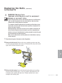
For Puller Model CPC 3-20
(continued)
4 Adjust belt tension, if necessary. Adjust tension by turning the threaded tension rods. Keep tension on front and back edges, top and bottom belts as even
as possible.
Threaded
tension rods
5 Fine-tune the tension:
• Lower the belts to a gap of about 1/8 in. (3 mm).
See Installation Section entitled, Setting the Belt Gap.
• Check the appearance of the belt gap. From the upstream end, look
down the length of the belts. The shape of the gap should not be
concave (over-tightened) or convex (too loose). Adjust the tension until
the gap is even.
• Check the tension and readjust as necessary.
3-12 l Installation
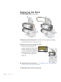
Setting the Belt Gap
For Puller Model CPC 1-12
The upper and lower belt boom assemblies are controlled by a common threaded
rod. Turn the hand wheel to move the belts up and down. The belt gap should be
set to the dimensions of the extruded product, being careful not to make the gap so
small that the pressure causes distortion in the product.
1 Turn the hand wheel until the gap between the belts reaches the desired distance.
For Puller Model CPC 3-20
The upper and lower belt boom assemblies are controlled
by a common threaded rod. The upper and lower belts
move away from each other or toward each other as the
hand wheel is turned. The belt gap should be set to the
dimensions of the extruded product, being careful not to
make the gap so small that the pressure causes distortion
in the product.
Hand wheel
1 Turn the hand wheel until the gap between the belts
reaches the desired distance.
Installation l 3-13
3
Installation
Hand wheel
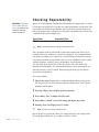
Checking Repeatability
IMPORTANT: See Operation
Section entitled, Tuning the
Cutter, if using Red Lion HMI
and Control Techniques/
Emerson Servo Drives
Before any Conair Medline Combination Puller/Cutters are shipped, they are tested
for cut time repeatability to be sure they are within performance specifications. The
repeatability test checks the performance of the rotary knife cutter to return to the
home park position after a complete cut. Acceptable repeatability times allowed for
each cutter model prior to shipping are:
Type of Cutter
CMSC Positional Servo
0
Repeatability Time
Less than 0.1 millisecond
NOTE: 1-millisecond at 60 feet per minute is equal to .012 inches.
The repeatability mode is built into the Conair cutter controls and allows you to
perform similar tests, without any external test equipment. It is recommended that
you check repeatability on a regular basis. Acceleration/deceleration delays of the
servo do not contribute to repeatability error; any error is attributed solely to motor
stability, couplings, assembly, power, and proximity sensor alignment.
Use any blade speed and line speed. The line speed is only seen while in the
Encoder or Product Modes. It is recommended that the tests be performed at cut
intervals between 0.5 and 5-seconds. Do not change the blade speed or the line
speed after starting the test.
To test repeatability:
1 Turn on the cutter. Perform the test in Encoder Mode with the cutter on-line.
The Display will read: DevCP shows problems with the cutter. DevCC shows
problems with the puller.
2 Press the “Menu” key to display operator functions.
3 Press softkey “Test” to display DevCP screen.
4 Press softkey “On/Off” to start the testing and display the results.
5 Pressing “Next” key displays DevCC results.
0
NOTE: “Previous” key returns to DevCP screen.
Repeat the test by pressing the “Reset Cut” button to begin a new sample period.
To end the Repeatability test, press softkey “On/Off” or “Exit”.
3-14 l Installation
R e p e a t a b i l i t y Te s t R e s u l t s
Results in Flywheel Mode
The display shows DevCC a full revolution of the cutter head. The reading is in
milliseconds, to the third decimal place, i.e. 0.010 is 0.01 milliseconds (or 10
microseconds). If the reading exceeds 0.200 there is a problem with the cutter
drive. If this occurs the error is too large and there is a problem in the cutter drive
that must be corrected.
IMPORTANT: See Operation
Section entitled, Tuning the
Cutter, if using Red Lion HMI
and Control Techniques/
Emerson Servo Drives
Results in Timer Mode
When testing repeatability in Timer Mode, the cutter is making on-demand cuts at
a set time interval (i.e. one-second intervals). The display shows the cut-to-part
(CP) reading and the cut-to-cut (CC) reading. The reading is in milliseconds, to the
third decimal place, i.e. 0.010 is 0.01 milliseconds (or 10 microseconds).
CC is the peak time variance between cuts. Record and compare the cut-to-cut
number to the CC value recorded in Encoder or Product Mode shows how much
error is by external influences (i.e. variation in belt puller speed, encoder mounting
problem, etc.).
If the reading exceeds 0.200, there is a problem with the cutter drive. If this occurs
the error is too large and there is a definite problem that must be corrected.
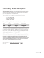
Results in Product Mode
The display shows the cut-to-part (CP) reading and the cut-to-cut (CC) reading.
The reading is in milliseconds, to the third decimal place, i.e. 0.010 is 0.01 milliseconds (or 10 microseconds).
Compare the cut-to-part (CP) reading to the CP reading in the other modes. There
should be very little difference in these readings.
Compare the cut-to-cut (CC) reading to the CC reading in the other modes. Since
the Product Mode is influenced by external signals, this reading will reflect the
speed regulation of the puller.
Installation l 3-15
3
Installation
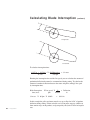
CP is the peak time variance between the cut signal output (preset time) to the
servo amplifier, and the programmable limit switch just prior to the center of the
bushing. This is the repeatability of the cutting system to accelerate through the
part. This value is higher than the CC reading since it includes the acceleration and
deceleration contributed by the servo motor.
P r e p a r i n g f o r Te s t i n g
1 Make sure all components are installed according to assembly drawings.
Make sure that all bolts have been checked for tightness.
2 Check to ensure that the combination puller/cutter is firmly locked into
position with the anchoring screws.
3 Check that all wiring conforms to electrical codes, and all wiring covers are
in place.
DANGER: Pinch Hazard!
Never remove or disable safety devices to sustain production. Operating
without these devices could lead to hazardous conditions that can cause
severe injury. Take all necessary precautions when working around moving
parts to prevent body parts and clothing from being pulled into the machine.
3-16 l Installation
Te s t i n g t h e I n s t a l l a t i o n
Tw o - L i n e H M I I n t e r fa c e O p e r a t i o n
1 Plug in the main power cord and turn on the main disconnect. The display
should fully illuminate and start up. Power on lights will illuminate.
2 Check that the “Emergency Stop” buttons are in the out, extended position.
0
NOTE: If the “Emergency Stop” button is pushed in, there will be no power applied to the amplifier and the operator interface will display “starting commands” for an extended period of time.
3 Make sure that the Cut On/Off switch is Off. If necessary, press button to
4 Press “Start Puller” button. The puller must be activated before the cutter
portion can be turned on. Once the puller is running press the start button for
the cutter section, the blade will begin to rotate.
0
NOTE: For more information about setting and adjusting the gap for the bushings, see
Appendix C, About Cutter Bushings.
5 Open the knife guard. The machine start push button should go out.
If the cutter is not working properly at any time, turn it off immediately and refer
to the Troubleshooting section of this User Guide.
If you do not encounter any problems, proceed to the Operation section.
(continued)
Installation l 3-17
3
Installation
display off.
Te s t i n g t h e I n s t a l l a t i o n
(continued)
To u c h s c r e e n H M I I n t e r fa c e O p e r a t i o n
1 Plug in the main power cord and turn on the main disconnect. The display
should fully illuminate and start up. Power on lights will illuminate.
2 Check that the “Emergency Stop” buttons are in the out, extended position.
0
NOTE: If the “Emergency Stop” button is pushed in, there will be no power applied to the amplifier and the operator interface will display “starting commands” for an extended period of time.
3 Make sure that the Cut On/Off switch is Off. If necessary, press button to
display off.
4 Press “Start Puller” button. The puller must be activated before the cutter
portion can be turned on. Once the puller is running press the “Start” button for
the cutter section, the blade will begin to rotate.
0
NOTE: For more information about setting and adjusting the gap for the bushings,
see Appendix C, About Cutter Bushings.
5 Open the knife guard. The cutter will stop and the touchscreen on the Main
Page will display “Stopped” above the cutter section of the control.
If the cutter is not working properly at any time, turn it off immediately and refer
to the Troubleshooting section of this User Guide.
If you do not encounter any problems, proceed to the Operation section.
3-18 l Installation
SECTION
Operation
.
.
.
.
.
.
.
.
.
.
.
.
.
.
.
.
.
.
.
.
.
.
.
.
.
.
.
.
.
.
.
.
.
.
.
.
.
.
.
.
.
.
.
.
.
.
.
.
.
.
.
.
.
.
.
.
.
.
.
.
.
.
.
.
.
.
.
.
.
.
.
.
.
.
.
.
.
.
.
.
. 4-5
. 4-6
. 4-7
. 4-8
. 4-8
. 4-9
. 4-9
4-11
4-11
4-12
4-12
4-13
4-14
4-14
4-15
4-16
.
.
.
.
.
.
.
.
.
.
.
.
.
.
.
.
.
.
.
.
.
.
.
.
.
.
.
.
.
.
.
.
.
.
.
.
.
.
.
.
.
.
.
.
.
.
.
.
.
.
.
.
.
.
.
.
.
.
.
.
.
.
.
.
.
.
.
.
.
.
.
.
.
.
.
.
.
.
.
.
.
.
.
.
.
.
.
.
.
.
.
.
.
.
.
.
.
.
.
.
.
.
.
.
.
.
.
.
.
.
.
.
.
.
.
.
.
.
.
.
.
.
.
.
.
.
.
.
.
.
.
.
.
.
.
.
.
.
.
.
.
.
.
.
.
.
.
.
.
.
4-18
4-19
4-20
4-21
4-21
4-21
4-22
4-23
4-23
4-24
4-24
4-25
4-25
4-25
4-26
4-26
4-26
4-27
4-28
4-28
4-29
4-31
4-32
4-33
4-34
4-36
4-37
4
Operation l 4-1
4
.
.
.
.
.
.
.
.
.
.
.
.
.
.
.
.
Operation
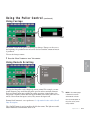
Conair Medline Combination Puller/CutterTouch panel . . . . . . . . . . . . . . . . . . .
Using the main page . . . . . . . . . . . . . . . .
Using folder tabs . . . . . . . . . . . . . . . .
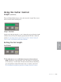
Using the puller control . . . . . . . . . . . . . .
Setting the puller speed . . . . . . . . . . .
Scroll method . . . . . . . . . . . . . .
Keyboard method . . . . . . . . . . . .
Using footage . . . . . . . . . . . . . . . . . .
Using remote scrolling . . . . . . . . . . . .
Switched (Local/Remote) modes . . . . .
Analog trim modes . . . . . . . . . . . . . . .
Storing the belt gap . . . . . . . . . . . . . . . . .
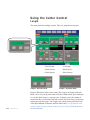
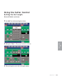
Using cutter control . . . . . . . . . . . . . . . . .
Length . . . . . . . . . . . . . . . . . . . . . . .
Setting cut length . . . . . . . . . . . . . . .
Keyboard method . . . . . . . . . . . .
Using Encoder Sequence, Cuff and
Profile/Bubble/Taper modes . . . . .
Setting blade speed . . . . . . . . . . . . . . . . .
Using multiple blades . . . . . . . . . . . . . . . .
Using 180 degree cutting (optional) . . . . . .
Configuring the blow off settings (optional) .
Offset . . . . . . . . . . . . . . . . . . . . . . .
Time . . . . . . . . . . . . . . . . . . . . . . . .
Blow amount . . . . . . . . . . . . . . . . . . .
Blow activation . . . . . . . . . . . . . . . . .
Style
Good and bad indicators . . . . . . . . . . .
Scrap/Sort . . . . . . . . . . . . . . . . . . . .
Using the total and batch counter . . . . . . . .
Total counter . . . . . . . . . . . . . . . . . .
Batch counter . . . . . . . . . . . . . . . . . .
Configuring the batch settings . . . . . . . . . .
Set . . . . . . . . . . . . . . . . . . . . . . . .
Warn
Pulse/Latch . . . . . . . . . . . . . . . . . . .
Alarm . . . . . . . . . . . . . . . . . . . . . . . .
Accessing secured pages and presets . . . . .
Using file pages . . . . . . . . . . . . . . . . . . . .
Opening a file . . . . . . . . . . . . . . . . . .
Deleting a file . . . . . . . . . . . . . . . . . .
Saving a file . . . . . . . . . . . . . . . . . . .
File contents . . . . . . . . . . . . . . . . . . . . . .
Configuring the network settings . . . . . . . .
Operation
4-2 l Operation
(continued)
Changing the password . . . . . . . . . . . .
Using the events page . . . . . . . . . . . .
Using the faults page . . . . . . . . . . . . .
Using the IO page. . . . . . . . . . . . . . . .
Diagnostics character . . . . . . . . .
Debounce . . . . . . . . . . . . . . . . . .
Configuring the set up 1 folder . . . . . .
Modes page . . . . . . . . . . . . . . . .
Selecting modes . . . . . . . . . . . . .
Mode page descriptions - Puller modes .
Mode page descriptions - Cutter modes
Scroll page descriptions . . . . . . . . . . .
Cutter scrolls - Panel . . . . . . . . . .
Puller scrolls - Panel . . . . . . . . . .
Puller scrolls - Remote contacts . .
Puller scrolls - Remote digital pot .
Encoders page description. . . . . . . . . .
Ramps page description . . . . . . . . . . .
Cutter . . . . . . . . . . . . . . . . . . . .
Puller . . . . . . . . . . . . . . . . . . . . .
Scale page description . . . . . . . . . . . .
Cutter - Encoder input . . . . . . . . .
Puller - Encoder input . . . . . . . . .
Puller - Encoder output . . . . . . . .
Puller - Belt scale . . . . . . . . . . . .
Maximum speed volts . . . . . . . . . .
Analog input . . . . . . . . . . . . . . . .
Trim modes - Authority . . . . . . . . .
Remote digital potentiometer . . . .
Scale units . . . . . . . . . . . . . . . . .
Angles page description . . . . . . . . . . .
Park angle . . . . . . . . . . . . . . . . .
Cut angle . . . . . . . . . . . . . . . . . .
Set up 2 page description . . . . . . . . . .
Tuning the belt drive . . . . . . . . . .
Tuning the cutter . . . . . . . . . . . . .
Quality page description . . . . . . . . . . .
Offsets . . . . . . . . . . . . . . . .
Input polarity . . . . . . . . . . . .
When bad . . . . . . . . . . . . . .
Counters . . . . . . . . . . . . . . .
Take away/Blow off . . . . . . . . . . . . . .
Deferred sample . . . . . . . . . . . . .
Factor y page description . . . . . . . . . . .
About page . . . . . . . . . . . . . . . . . . . .
.
.
.
.
.
.
.
.
.
.
.
.
.
.
.
.
.
.
.
.
.
.
.
.
.
.
.
.
.
.
.
.
.
.
.
.
.
.
.
.
.
.
.
.
.
.
.
.
.
.
.
.
.
.
.
.
.
.
.
.
.
.
.
.
.
.
.
.
.
.
.
.
.
.
.
.
.
.
.
.
.
.
.
.
.
.
.
.
.
.
.
.
.
.
.
.
.
.
.
.
.
.
.
.
.
.
.
.
.
.
.
.
.
.
.
.
.
.
.
.
.
.
.
.
.
.
.
.
.
.
.
.
.
.
.
.
.
.
.
.
.
.
.
.
.
.
.
.
.
.
.
.
.
.
.
.
.
.
.
.
.
.
.
.
.
.
.
.
.
.
.
.
.
.
.
.
.
.
.
.
.
.
.
.
.
.
.
.
.
.
.
.
.
.
.
.
.
.
.
.
.
.
.
.
.
.
.
.
.
.
.
.
.
.
.
.
.
.
.
.
.
.
.
.
.
.
.
.
.
.
.
.
.
.
.
.
.
.
.
.
.
.
.
.
.
.
.
.
.
.
.
.
.
.
.
.
.
.
.
.
.
.
.
.
.
.
.
.
.
.
.
.
.
.
.
.
.
.
.
.
.
.
.
.
.
.
.
.
.
.
.
.
.
.
.
.
.
.
.
.
.
.
.
.
.
.
.
.
.
.
.
.
.
.
.
.
.
.
.
.
.
.
.
.
.
.
.
.
.
.
.
.
.
.
.
.
.
.
.
.
.
.
.
.
.
.
.
.
.
.
.
.
.
.
.
.
.
.
.
.
.
.
.
.
.
.
.
.
.
.
.
.
.
.
.
.
.
.
.
.
.
.
.
.
.
.
.
.
.
.
.
.
.
.
.
.
.
.
.
.
.
.
.
.
.
4-38
4-39
4-40
4-41
4-42
4-43
4-44
4-44
4-46
4-47
4-50
4-53
4-53
4-55
4-56
4-58
4-60
4-60
4-60
4-62
4-64
4-65
4-66
4-68
4-69
4-70
4-73
4-74
4-75
4-76
4-77
4-78
4-79
4-80
4-81
4-84
4-86
4-86
4-88
4-89
4-90
4-90
4-90
4-91
4-92
Operation
(continued)
.
.
.
.
.
.
.
.
.
.
.
.
.
.
.
.
.
.
.
.
.
.
.
.
.
.
.
.
.
.
.
.
.
.
.
.
4-93
4-94
4-95
4-96
4-97
4-98
.
.
.
.
.
.
.
.
.
.
.
.
.
.
.
.
.
.
.
.
.
.
.
.
.
.
.
.
.
.
.
.
.
.
.
.
.
.
.
.
.
.
.
.
.
.
.
.
.
.
.
.
.
.
.
.
.
.
.
.
.
.
.
.
.
.
.
.
.
.
.
.
.
.
.
.
.
.
.
.
.
.
.
.
.
4-100
4-101
4-102
4-102
4-104
4-104
4-105
4-106
4-107
. . . .
4-108
4-109
4-112
4-113
4-114
4-115
4-118
. . . . . 4-119
. . . . . 4-124
. . . . . 4-125
. . . . . 4-128
.
.
.
.
.
.
.
.
.
.
.
.
.
.
.
.
.
.
.
.
.
.
.
.
.
.
.
.
.
.
.
.
.
.
.
.
.
.
.
.
.
.
.
.
.
.
.
.
.
.
.
.
.
.
.
.
.
.
.
.
.
.
.
.
.
4-129
4-130
4-131
4-132
4-132
4-134
4-137
4-138
4-139
4-140
4-141
4-142
4-143
Operation l 4-3
4
Operation
Encoder sequence page description . . . . . .
Setting sequence lengths . . . . . . . . . .
Cuff page description . . . . . . . . . . . . . . . .
Trigger settings . . . . . . . . . . . . . . . . .
Gate off distance . . . . . . . . . . . . . . . .
Cuts . . . . . . . . . . . . . . . . . . . . . . . .
Profile/Bubble/Taper modes - Profile page
description . . . . . . . . . . . . . . . . . . . .
Puller . . . . . . . . . . . . . . . . . . . . . . . .
Velocity (FPM) . . . . . . . . . . . . . .
Sequence length . . . . . . . . . . . . .
Cutter . . . . . . . . . . . . . . . . . . . . . . .
Location offset . . . . . . . . . . . . . .
Additional cuts 1 and 2 . . . . . . . .
Body off cut . . . . . . . . . . . . . . . .
On line/off line . . . . . . . . . . . . . .
Profile/Bubble/Taper modes - Velocity page .
Description . . . . . . . . . . . . . . . . . . . .
Index . . . . . . . . . . . . . . . . . . . . . . . .
Ramp type . . . . . . . . . . . . . . . . . . . .
Key . . . . . . . . . . . . . . . . . . . . . . . .
Drive data . . . . . . . . . . . . . . . . . . . . .
Ratio calculator . . . . . . . . . . . . . . . . .
Zoom . . . . . . . . . . . . . . . . . . . . . . . .
Profile/Bubble/Taper modes - Analog page
description . . . . . . . . . . . . . . . . . . . .
Profile/Bubble/Taper modes - Digital output
page description . . . . . . . . . . . . . . . .
Setting output length and duration . . . .
Profile/Bubble/Taper modes - Graph all page
description . . . . . . . . . . . . . . . . . . . .
Profile/Bubble/Taper modes - Gauge control
page description . . . . . . . . . . . . . . . .
Cutter operator control features . . . . . . . . .
Cutter operator instructions main screen . . .
Cutter control instructions . . . . . . . . . . . . .
Total screen . . . . . . . . . . . . . . . . . . .
Batch screen . . . . . . . . . . . . . . . . . . .
Length screen . . . . . . . . . . . . . . . . . . . . .
Preset to run screen . . . . . . . . . . . . .
Time screen . . . . . . . . . . . . . . . . . . .
Hold-off screen . . . . . . . . . . . . . . . . .
Blade speed screen . . . . . . . . . . . . . .
Blade count screen . . . . . . . . . . . . . .
Cutter control instructions . . . . . . . . . . . . .
Operation
(continued)
Functions areas . . . . . . . . . . . . . . . . .
Test . . . . . . . . . . . . . . . . . . . . . . . .
Cut mode . . . . . . . . . . . . . . . . . . . . .
Minimum measurement . . . . . . . . . . . .
Maintenance area . . . . . . . . . . . . . . .
Encoder area . . . . . . . . . . . . . . . . . . .
Encoder direction. . . . . . . . . . . . . . . .
Unit of measure . . . . . . . . . . . . . . . . .
Scale distance . . . . . . . . . . . . . . . . . .
Scales counts . . . . . . . . . . . . . . . . . .
Homing . . . . . . . . . . . . . . . . . . . . . . .
Home offset . . . . . . . . . . . . . . . . . . .
Offset example . . . . . . . . . . . . . . . . .
Power on time . . . . . . . . . . . . . . . . . .
Cutter power up . . . . . . . . . . . . . . . . . . . .
Puller operation control . . . . . . . . . . . . . . .
Puller operation control features . . . . . . . .
Puller operation control instructions . . . . . .
Main screen . . . . . . . . . . . . . . . . . . .
Programming scroll increments . . . . . .
Using scroll increments . . . . . . . . . . .
Operator entered speed change . . . . . .
Footage counter . . . . . . . . . . . . . . . .
Diagnostics screen. . . . . . . . . . . . . . .
Puller speed remote . . . . . . . . . . . . . .
Before starting the combination Unit . . . . . .
Start-up preparations for puller . . . . . . . . .
Powering up . . . . . . . . . . . . . . . . . . . . . .
Programming the puller speed . . . . . . . . . .
Starting the puller . . . . . . . . . . . . . . . . . .
Stopping the puller . . . . . . . . . . . . . . . . . .
Shutting down the puller . . . . . . . . . . . . . .
Combination control features . . . . . . . . . . .
Setting the scale factor . . . . . . . . . . . . . . .
Checking the cut quality . . . . . . . . . . . . . .
Setting the cutting mode - Two line HMI
interface operation . . . . . . . . . . . . . .
Making Adjustments during operation for
the cutter . . . . . . . . . . . . . . . . . . . . .
Stopping only the cutter . . . . . . . . . . . . . .
Stopping the Combination Puller/Cutter . . . .
Shutting down the Combination Puller/Cutter
4-4 l Operation
.
.
.
.
.
.
.
.
.
.
.
.
.
.
.
.
.
.
.
.
.
.
.
.
.
.
.
.
.
.
.
.
.
.
.
.
.
.
.
.
.
.
.
.
.
.
.
.
.
.
.
.
.
.
.
.
.
.
.
.
.
.
.
.
.
.
.
.
.
.
.
.
.
.
.
.
.
.
.
.
.
.
.
.
.
.
.
.
.
.
.
.
.
.
.
.
.
.
.
.
.
.
.
.
.
.
.
.
.
.
.
.
.
.
.
.
.
.
.
.
.
.
.
.
.
.
.
.
.
.
.
.
.
.
.
.
.
.
.
.
.
.
.
.
.
.
.
.
.
.
.
.
.
.
.
.
.
.
.
.
.
.
.
.
.
.
.
.
.
.
.
.
.
.
.
4-143
4-144
4-146
4-147
4-147
4-148
4-149
4-150
4-152
4-153
4-154
4-154
4-156
4-157
4-158
4-159
4-160
4-161
4-161
4-162
4-163
4-164
4-165
4-166
4-167
4-168
4-169
4-171
4-171
4-172
4-173
4-173
4-173
4-174
4-174
. . . . . 4-175
.
.
.
.
.
.
.
.
.
.
.
.
.
.
.
.
.
.
.
.
4-176
4-177
4-178
4-178
Conair Medline Combination
P u l l e r / C u t t e r - To u c h Pa n e l
The Conair Medline Combination Puller/Cutter uses a common Red Lion G310
color touchscreen operator interface. Touchscreens provide a user-friendly interface to the puller/cutter. Information can be shown while maintaining an easy-toread and easy-to-use environment.
On the left-hand side of the panel are seven general-purpose buttons and a
“Menu” button, these are not used in this application. Touchscreen buttons that
are used appear on the screen. In many cases the appearance of text on the
switches will change to show its state (e.g. on or off).
At power-up the Flash Page appears briefly followed by the Main Page.
4
Operation
Operation l 4-5
U s i n g t h e M a i n Pa g e
The Main Page appearance is affected by the modes that have been selected for
the Medline Combination Puller/Cutter.
In the Main Page example, the puller is set to Master Mode and the cutter is set to
Encoder Mode. The chosen mode appears at the bottom of each control section.
Tabs
Stopped or
Running
Date/Time
Mode
(continued)
4-6 l Operation
U s i n g t h e M a i n Pa g e
(continued)
U s i n g F o l d e r Ta b s
A series of folder tabs appear at the top of every page. Each folder contains a page
containing further parameters, selections or more folders. Tabs act as a simplified
menu to move between pages. The last tab pressed opens the folder to show the
page(s) contained inside. Highlighted tabs appear darker in shade compared to
unselected tabs. In the example below, the “Main” tab has been selected.
Sample of a single-tiered tab page.
To select a specific tab:
1 Press the desired tab to access additional puller/cutter parameters.
0
Sample of a double-tiered tab page.
To select a specific sub-tab:
1 Press the desired main tab to access additional puller/cutter parameters.
(Set Up 1 and Set Up 2 tabs have double-tiered tab folders)
2 Select the desired sub-tab within the main tab page.
0
NOTE: Tab pages selected will remain on the puller/cutter’s display screen until a new tab is
selected.
Operation l 4-7
4
Operation
NOTE: Tab pages selected will remain on the puller/cutter’s display screen until a new tab is
selected.
Using the Puller Control
For right-to-left configurations the cutter control is shown on the left with the
puller control on the right, as in the example. Images of the controls may be
switched at the factory for left-to-right combinations.
A message appears above each control to show if the drive is running or stopped.
"Running" is shown as white text on a green background and "Stopped" is shown
as white text on a red background. The cutter cannot run alone - it is interlocked
with the puller, meaning that the puller must be running before the cutter can run.
Likewise, if the puller is stopped the cutter will stop.
Setting the Puller Speed
Speed Control
The Main Page is used to view and set speed. Speed may be changed by using the
(+) and (-) buttons that are just below the speed readout (Scroll Method) or they
may be keyed in using a pop-up keyboard (Keyboard Method).
IMPORTANT: For Profile/Bubble/Taper products speed is controlled by a different
program, it cannot be changed here.
(continued)
4-8 l Operation
Using the Puller Control
Setting the Puller Speed
(continued)
Scroll Method
The (+) and (-) buttons can be used to add or subtract the value shown in the
Scroll Size window to the current speed setting. Scroll Size is a user preference
value. Four presets are available but only one may be selected at any given time.
In the example, the chosen Scroll Size is set to ±0.10 FPM.
To enter a new puller speed:
1 Press either the (+) or (-) scroll button to increase or decrease the set
speed. For example, 40 FPM becomes 40.10 FPM after pressing (+) once. The
(-) button will subtract 0.10 FPM from the current set speed - example 40 FPM
becomes 39.90 FPM after pressing (-) once.
Typically, the operator will choose four values from fine to coarse that would be
used for control of the line. An example is 0.01, 0.10, 1.00 and 5.00 FPM.
Pressing the Scroll Size window will toggle through the four preset increments.
0
NOTE: To set new scroll
increments, see Operation
1 Press the window showing the puller speed. A pop-up keyboard appears.
2 Enter in your new value on the pop-up key pad.
3 Press the “Enter” button to lock in the new puller speed. The pop-up key
board is removed.
0
NOTE: In this example, cut
length is being altered.
The procedure to change
any measurement using
the Keyboard method is
exactly the same.
(continued)
Operation l 4-9
4
To enter a new puller speed:
Operation
Section entitled, Scroll
Page Description.
Keyboard Method
Using the Puller Control
Setting the Puller Speed
0
NOTE: In this example, cut
length is being altered.
(continued)
A title appears at the top of the pop-up keyboard to confirm which preset is being
modified. See Operation Section entitled, Using the Cutter Control, Setting the
Cut Length. The explanation given in that section applies to changing any preset.
The procedure to change
any measurement using
the Keyboard method is
• If the pop-up is accessed by mistake press “Exit” to remove it. Also, if an incorrect value is entered press “Exit” to retain previous value.
exactly the same.
• “Raise” and “Lower” buttons will add or subtract one least significant digit,
i.e. for two decimal places the value will change by 0.01, for three decimal
places the value will change by 0.001.
• “Prev” and “Next” buttons are used to go to the next preset on the page. If
there is only one preset on the page the preset will remain selected.
• The (+/-) key should not be used - all values are positive. All presets are range
checked, a negative value will be ignored.
All numeric presets use the same style numeric keyboard. A computer style keyboard appears for text presets, i.e. user or filename entry.
4-10 l Operation
Using the Puller Control
(continued)
Using Footage
The middle section of the puller control displays footage. Footage can be reset at
the beginning of a production run and can be used to record the amount of material produced.
To reset the footage counter:
1 Press the “Reset” button to “zero” the counter.
Remote Scroll amount is a user preference. See Operation Section entitled, Scroll
Page Description.
The “On/Off” button is used to enable or disable the remote. The light next to this
button illuminates when Remote Scroll is on.
0
NOTE: If the remote gauge
is fitted with a manual
and automatic selector
then the remote option at
the puller can be permanently enabled.
Operation l 4-11
4
The speed of the puller can be changed by remote control. For example, an automated diameter gauge could alter the puller speed in order to maintain diameter.
Raise and Lower inputs are available for remote operation. A simple three-wire
integration is required. LEDs show the input condition at the Raise and Lower terminals. Green means the input is active, Gray means the input is off.
Operation
Using Remote Scrolling
Using the Puller Control
(continued)
Switched (Local/Remote) Modes
This section will have additional buttons and indicators for Switched or Trim
Modes. Extra mode related items appear at the right.
Switched modes include a Local/Remote “Select” button and indicators. The state
of Local or Remote is provided as an output at the puller drive (Module Output 3).
Remote = On, Local = Off.
A n a l o g Tr i m M o d e s
Analog Trim modes will have a Trim “On/Off” button and indicator. Puller speed
can be modified by the analog input when enabled.
4-12 l Operation
Storing the Belt Gap
The belt gap dimension can be stored here. The value should be read from the belt
gap gauge and entered at this window. When returning to a product that was previously produced the user can recall the recipe value by viewing the saved file and
then setting the belt gap to match. See Operation Section entitled, Using Files
Pages, File Pages.
1 View the belt gap measurement from the digital readout located on the
Medline Combination Puller/Cutter’s cabinet.
2 Press the window showing the puller belt gap. A pop-up keyboard appears.
3 Enter in your new value on the pop-up key pad.
4 Press the “Enter” button to lock in the new puller belt gap. The pop-up key
board is removed.
To set the belt gap from the file recipe:
1 Open the file page that contains the desired product recipe.
2 Locate the belt gap distance within the save file page.
3 Match the digital belt gap readout on the puller/cutter’s cabinet to the
amount from the saved file page recipe using the manual hand wheel located
on the puller.
4 Enter the belt gap measurement in the Belt Gap window, by following the
following the “Setting the belt gap from the digital readout” steps.
Operation l 4-13
4
Operation
To set the belt gap from the digital readout:
Using the Cutter Control
Length
The cutter portion has multiple sections. These are grouped into categories.
• Total Counter
• Cut Length
• Batch Counter
• Blade Speed
• Batch Settings
• Blow Settings
Sample - Encoder Mode
4-14 l Operation
Sample - Flywheel Mode
Features differ between the various modes. For example, the length in Encoder
Mode can be set by the operator whereas Flywheel Mode (blade spins continuously) can only show length as a captured value. Captured value is the amount of
material that has passed during each blade rotation, the blade arriving at the cutter
bushing provides the capture. Cut Length can be changed using either the Scroll
or Keyboard Methods in Encoder and Time Modes only. See Operation Section
entitled, Using the Cutter Control, Setting the Cutter Length, Scroll Method and
Keyboard Methods.
Using the Cutter Control
Length
(continued)
Timer and Product Modes display a time value instead of a length. Time is measured in seconds to three decimal places.
Sample - Time Mode
Length can be changed using the (+) and (-) buttons that are just below the length
readout or it may be keyed in using the pop-up keyboard. The time is shown in
seconds. See Operation Section entitled, Using the Cutter Control, Setting the
Cutter Length, Scroll Method and Keyboard Methods
Scroll Method
1 Press either the (+) or (-) scroll button to increase or decrease the cut
length. Scroll Size is a user preference value. Two settings are available and
are set in Set Up 1 - Scroll section. To alternate between the two Scroll Sizes,
press the Scroll Size window. The default values are ±0.010" and ±0.100".
See Scroll Page Description for procedures to change Scroll Size settings.
Operation l 4-15
4
Operation
Setting the Cut Length
Using the Cutter Control
Setting the Cut Length
(continued)
Keyboard Method
To change length using the keyboard method, press the Length window. A pop-up
keyboard will appear. The new length can then be keyed in.
All numeric presets are altered using this method. An example of how to change
the length is provided to help describe the key sequence. In this example, Length
is 2.750" and will be changed to 6.000".
1 Press the length window. A numeric pop-up keyboard appears.
(continued)
4-16 l Operation
Using the Cutter Control
Setting the Cut Length
Keyboard Method ( c o n t i n u e d )
2 For 6.000" key in the new length as shown.
4 The new length is now in the Cut Length window.
Operation l 4-17
4
Operation
3 Then press “Enter”. (The pop-up keyboard is removed).
Using the Cutter Control
Using Encoder Sequence, Cuff and
P r o f i l e / B u b b l e / Ta p e r M o d e s
Encoder Sequence, Cuff and Profile/Bubble/Taper Modes have many length presets. There are too many to be able to show on the Main Page. The length section
on the Main Page for these modes is replaced by a button that is used to go to a
secondary page that contains the extra presets.
Sample of the Main Page with Profile/Bubble/Taper Mode selected.
0
NOTE: Above is the button that is shown is for Profile/Bubble/Taper Mode. Encoder
Sequence Mode has a button labeled "Sequence Settings" and Cuff Mode has a button
labeled "Cuff Settings". See Operation Section entitled, Mode Page Description and
Profile/Bubble/Taper Page Description, Encoder Sequence Page Description and Cuff
Page Description.
4-18 l Operation
Setting the Blade Speed
Sample - Flywheel Mode showing Blades preset (for multiple blades)
NOTE: Blade Speed adjustment is an option, on some cutters Blade Speed will be fixed.
To adjust the blade speed:
1 Press the Blade Speed window. A numeric pop-up keyboard appears.
2 Key in the new blade speed.
3 Then press “Enter”. The pop-up keyboard is removed.
4 The new blade speed is now in the Blade Speed window.
Operation l 4-19
4
Operation
Blade Speed shows the RPM of the blade. In some modes it is possible to set the
Blade Speed. In other modes Blade Speed may be viewed only. Press this window
to access the Blade Speed preset.
Using Multiple Blades
Multiple blades may be entered and fitted for Flywheel and Follower modes only.
An additional preset will appear in Blade Speed section for entering the amount of
blades. Also, a circular or balanced arm style blade holder will be fitted for the
extra positions. Blade Speed will then appear as Cuts per Minute (CPM) instead
of RPM.
CPM = Blade Speed x Number of Blades.
Blade options for Follower and Flywheel Modes.
Blades
1
2
3
4
5
6
7
8
9
10
11
12
Angle
360
180
120
90
72
60
No Option
45
40
36
No Option
30
To adjust the number of blades:
1 Press the Blades window. A numeric pop-up keyboard appears.
2 Key in the amount of blades that are being used.
3 Then press “Enter”. The pop-up keyboard is removed.
4 The new blade amount will appear in the Blades window.
4-20 l Operation
Using 180 Degree Cutting
(Optional)
An option is available for use with the Encoder Mode where 2 blades may be fitted to the blade arm. The cut then makes 180-degree on-demand indexes (half a
revolution). 180 and 360-degree buttons are provided when this option has been
added.
Configuring the Blow Off Settings
(Optional)
A dedicated output is available for use with a Blow Off/Take Off Conveyor. This
output is intended to operate a valve to blow good pieces from the Take Off
Conveyor after they have been cut.
Offset
To adjust Offset amount:
1 Press the Offset window. A numeric pop-up keyboard appears.
2 Key in the new amount of offset amount, taking into account the
Take Off/Blow Off Conveyor’s speed and the puller speed.
3 Then press “Enter”. The pop-up keyboard is removed.
4 The new offset amount will appear in the Offset window.
Operation l 4-21
4
Operation
An offset preset length is available that acts as a delay from the cut. Distance
information is provided by the puller - not the Take Off/Blow Off Conveyor.
There is no distance information feedback available from the conveyor. In most
instances, the conveyor is set to travel faster than the puller in order to create piece
separation. This speed relationship will need to be factored in when setting the
Offset amount.
Configuring the Blow Off Settings
(Optional) (continued)
Ti m e
Time is the on-time duration for the air valve(s) of the Take Off/Blow Off
Conveyor. The time needed to eject the product should be kept short to avoid
exhausting accumulated air. The status of the air valve(s) will show in the
Blow/Quality section. An indicator light that is next the the word “Blow” will illuminate when the valve(s) is on.
To set the Time amount of the Take Off/Blow Off Conveyor’s air valve(s):
1 Press the Time window. A numeric pop-up keyboard appears.
2 Key in the new time amount, which is measured in seconds to two
decimal places.
3 Then press “Enter”. The pop-up keyboard is removed.
4 The new time amount will appear in the Time window and will then be
active.
4-22 l Operation
Configuring the Blow Off Settings
(continued) (Optional)
Blow Amount
Blow Amount is available to blow one or many pieces off the Take Off/Blow Off
Conveyor at once. For example, if the Blow Amount is set to 5 the Blow Off
valve(s) on the conveyor will blow once after 5 pieces have been cut.
To change the Blow Amount setting:
1 Press the Blow Amount window. A numeric pop-up keyboard appears.
3 Then press “Enter”. The pop-up keyboard is removed.
4 The new blow amount will appear in the Blow Amount window and will
then be active.
B l o w A c t i va t i o n
On/Off is used to enable or disable the Blow Off settings.
1 Press the “On/Off” button to toggle the Blow feature on and off. An indicator light next the the “On/Off” button will illuminate when the Blow feature is
activated.
Operation l 4-23
4
Operation
2 Key in the new blow amount.
Configuring the Blow Off Settings
(continued) (Optional)
Style
IMPORTANT: The options “Blow
always when Good” and “Blow
always when Bad” can expend a lot
of air. Their settings should be kept
low or not used when possible.
Pressing the “Style” button will toggle through three different Blow Settings.
Blow Amount as shown in the example above is one of the options. Other options
are "Blow always when Good", or "Blow always when Bad”.
• “Blow always when Good” - the Take Off/Blow Off Conveyor’s air will remain
energized (blowing) while the product is good, allowing product to be diverted
sideways off the conveyor. When the product is bad the valve will turn off so the
product will fall off the conveyor into a receptical. The Offset value is used
to delay the valve on or off times.
• “Blow always when Bad” - the Take Off/Blow Off Conveyor’s air will remain
energized (blowing) while the product is bad, allowing product to be diverted
sideways off the conveyor. When the product is good the valve will turn off so
the product will fall off the conveyor into a receptical. The Offset value is used
to delay the valve on or off times.
The quality input (good or bad) is used to control the air valve(s). No matter
which option is selected the air valve will always be off when the cutter is
stopped. See Operation Section entitled, Quality Page Description.
Quality - Good and Bad Indicators
• Gauge (Product Quality) Indicator - displays the quality of the product at the
gauge. It will illuminate green if the product is good and red if the product is
bad.
• Cutter (Product Quality) Indicator - displays the quality of the product at the
4-24 l Operation
cutter. It will illuminate green if the product is good and red if the product is
bad.
Configuring the Blow Off Settings
(continued) (Optional)
Scrap/Sort
The “Scrap/Sort” toggle button provides the option to force product to be
scrapped (even if it is good) or be sorted into good and bad by using the Quality
Sort feature. See Operation Section entitled, Quality Page Description.
U s i n g t h e To t a l a n d B a t c h C o u n t e r
To t a l C o u n t e r
To activate the Total Counter:
1 Press the “On/Off” button to toggle the Total Counter feature on and off.
When the Total Counter is on, an indicator light will illuminate.
To reset the Total Counter:
1 Press the “Reset “ button.
Operation l 4-25
4
Operation
An 8-digit Total Counter is provided with reset and on/off capabilities. Typically,
Total is used to display a count of all the pieces that were produced in a run.
When used with the Quality Sort feature, only good pieces are counted.
U s i n g t h e To t a l a n d B a t c h C o u n t e r
(Optional) (continued)
Batch Counter
The Batch Counter is a 6-digit readout display and is used with the Batch Settings
section that is located directly beneath the Total Counter. When used with the
Quality Sort feature only good pieces will be counted.
To activate the Batch Counter:
1 Press the “On/Off” button to toggle the Batch Counter feature on and off.
When the Batch Counter is on, an indicator light will illuminate.
To reset the Batch Counter:
1 Press the “Reset “ button.
Configuring the Batch Settings
(Optional)
Set
The Set preset is used to set the number of pieces that will make up a batch. An
output will operate upon batch completion. This output has a fixed pulse width
(1/10th second) or a latch-on option.
4-26 l Operation
Configuring the Batch Settings
(Optional)
Set
(continued)
To enter a Set amount:
1 Press the Set window. A numeric pop-up keyboard appears.
2 Key in the new set amount.
3 Then press “Enter”. The pop-up keyboard is removed.
Wa r n
The Warn preset is set to a value less than the Batch setpoint. This level activates
an operator warning that signifies a batch is near to completion. A yellow Warn
light is shown on the touch panel when the count is between Warn and Set values.
In addition, an output is available that can be used to operate an alarm (or tower
light). In this example, Warn is off during counts 0 to 14, it activates at count 15
and deactivates at 20 (count resets to zero, Warn alarm automatically clears). If the
Warn preset is higher than the Set amount it will be disabled.
To set the Warn amount:
1 Press the Warn window. A numeric pop-up keyboard appears.
2 Key in the new warn amount.
3 Then press “Enter”. The pop-up keyboard is removed.
4 The new warn amount will appear in the Warn window and will then be
active.
Operation l 4-27
4
Operation
4 The new set amount will appear in the Set window and will then be active.
Configuring the Batch Settings
(continued) (Optional)
Pulse/Latch
The “Pulse/Latch” button option offers the choice of making the output pulse or
latch on (stay on). The Latch option turns on the output, which will stay on until
the “Reset” button is pressed. The Pulse option will only pulse the output, which
will not require the “Reset” button to be pressed. In the Latch Mode there is an
extra light that is shown on the touch panel to show the state of the Batch
Complete output. The Warn output is automatically cleared when the Batch is
complete.
Pressing the “Pulse/Latch” button will toggle between the Latch and Pulse functions.
Alarm
The alarm function is used as a local alarm only. If a physical Batch Alarm output
is required the Warn or Latch options with outputs at the drive should be used. A
yellow batch complete light is shown as the Batch count reaches the Batch setpoint. The alarm feature has to be enabled in order to operate. “Reset” is then
used to clear the alarm. Pressing
“Reset” also clears a Latched Batch output.
4-28 l Operation
A c c e s s i n g S e c u r e d Pa g e s a n d
Presets
Some pages and presets require a user name and password for access. Only when
the user has successfully signed in will the protected page be displayed or a
changed in the preset be finalized.
In the following example the operator has pressed a tab requiring the user to sign
in (logon). A message appears - Secure Access Control - Must Authenticate to
Access Page.
To access the password protected screens:
maintenance personnel. enter "Maint" for the user name, followed by
the "Enter" button.
(continued)
Operation l 4-29
4
Operation
1 Press the Logon button to access an area to enter the user name. For
A c c e s s i n g S e c u r e d Pa g e s a n d
P r e s e t s (continued)
2 A second keyboard appears for password entry. Enter in the user password
0
0
“PASSWORD” followed by the “Enter” key.
NOTE: The password is a user preference, see Operation Section entitled, Changing the
Password to create a new password.
NOTE: The password characters do not appear as they are typed. An asterisk character
appears for each key press.
4-30 l Operation
U s i n g F i l e Pa g e s
The File Page screen has three sections. One section is used for creating, saving
and reopening files. Another section is for Ethernet. The remaining section is for
password creation and alteration.
To access the File Pages:
The filing system has a similar feel to any PC based software. Files may be created and recalled. The 8,3 DOS style of word naming is used (8 character filename
with a 3 character extension). Extensions are fixed to .CSV (comma separated
file). This is a format that can be opened using Excel or any text based word
processing software. A comma is used to separate each parameter and parameter
name.
0
A file may be created or saved at any time. However, files cannot be opened while
the machine is running. A warning message to this effect is given on the File Page
and again if an attempt to open a file is made.
Ethernet provides ability to upload and download files to computers sharing an
office network.
NOTE: The filing system is used
only with the Profile/Bubble/Taper
mode.
0
NOTE: The Medline’s IP address
can also be changed to match an
To access the Medline’s touch panel web server:
existing network. See Operation
1 Type in the Medline’s touch panel web server IP address as shown in the
Section entitled, Configuring the
Network Settings.
File Page sample above in the address bar of Internet Explorer. Be sure to
add http:// before the IP address. (http://192.168.0.20)
(continued)
Operation l 4-31
4
Operation
1 Press the File tab located at the top of the display screen.
U s i n g F i l e Pa g e s
Opening a File
Files are listed in alphabetical order. The "A-Z" and "Z-A" buttons provide
options to show files in alphabetical order or reversed alphabetical order.
To open a file:
1 Press the “Open” button that is located on the main File Page.
2 Once on the Open File Page, press directly on the file name or select the
file by using the “Up” or “Down” buttons. If there are more than ten files
saved within the File Pages, larger “Page Up” and “Page Down” arrow buttons
will be visible that will allow the user to scroll through the saved files, ten files
at a time. Double chevron arrows are used to indicate the file to be selected.
3 Press the “Open” button once the file to be open is highlighted.
IMPORTANT: Files can not be opened while the machine is running.
4-32 l Operation
U s i n g F i l e Pa g e s
(continued)
Deleting a File
A file may be deleted by using the arrow buttons and then pressing the “Delete”
button. A red warning appears detailing which file is about to be deleted with
options to keep or discard the file
To delete a file:
1 Press the “Open” button that is located on the main File Page.
buttons. If there are more than ten files saved within the File Pages, larger
“Page Up” and “Page Down” arrow buttons will be visible that will allow
the user to scroll through the saved files, ten files at a time. Double chevron
arrows are used to indicate the file to be selected.
3 Press the “Delete” button once to delete the file that is highlighted. A red
warning appears detailing which file is about to be deleted with options to
keep or discard the file.
4 Press the “Discard” button the delete the file or the “Keep” button to
keep the file.
To exit the Open File Page:
1 Press the “Exit” button to exit from this page. The current file will remain
open.
Operation l 4-33
4
Operation
2 Once on the Open File Page, select the file by using the “Up” or “Down”
U s i n g F i l e Pa g e s
(continued)
Saving a File
A file can be saved using the “Save” or “Save As...” buttons.
The “Save” button should be used when making changes to a file that is currently
open.
To update a current file using the “Save” button:
1 Press the “File” tab after changes have been made to the current running
program.
2 Press the “Save” button to update the current file.
The “Save As...” button is used when a new filename is required. An area is provided to enter the filename. Filenames must comply with the 8,3 DOS operating
system convention. There is no need to enter the .CSV extension. This has
already been filled in automatically.
To create a new file using the “Save As...” button:
1 Press the “File” after creating a new running program.
4-34 l Operation
2 Press the “Save As...” button to save the new file.
U s i n g F i l e Pa g e s
Saving a File
(continued)
4 Press the “Enter” button to lock in the new file name. The pop-up keyboard will be removed and the main File Page will be displayed.
Operation l 4-35
4
Operation
3 Enter in a new file name in the pop-up keyboard. (Up to eight characters)
U s i n g F i l e Pa g e s
(continued)
File Contents
0
NOTE: The “<” and “>” buttons
The contents of any saved file can be viewed using the File Contents feature.
From the File Page, you can select to view the contents of any file.
are used only to scroll sideways
if there are multiple columns.
To view the contents of a file:
1 Press the File tab, if not currently at the File Page.
2 Press the “View File Contents” button. A File Contents Page will be
displayed.
3 Use the “Up” and “Down” buttons to scroll through the file contents.
4 Press the “Exit” button when finished viewing file contents.
It is possible to view the contents of other files by using the “Next” and “Prev”
buttons. The filename of the file that is being viewed will be displayed at the top
of the File Contents Page.The sample above shows how to view the contents of a
specific file.
4-36 l Operation
Configuring the Network Settings
The Medline Combination Puller/Cutter’s touch panel has Ethernet capabilities.
For the Ethernet to function correctly the control must be set to conform to the
current network. The control must be rebooted for new settings to take effect. This
can be achieved by cycling the power on the control or by pressing the “Update”
button.
To setup or update the Network Settings:
1 Press the setting to be configured or updated. (IP Address, Subnet Mask, IP
Gateway or Mac ID)
2 A pop-up keyboard will appear, enter in the required setting and press
“Enter”. The keyboard will be removed.
3 Press the “Update” button to use the new settings.
The options are to “Reboot” or “Exit”. An interruption to the program happens
during the reboot. DO NOT REBOOT WHILE THE MACHINE IS RUNNING. Network configuration is typically done only once.
Operation l 4-37
4
Operation
The “Update” button reboots the panel. A warning is given to ensure the operator
is fully aware of what is about to happen.
C h a n g i n g t h e Pa s s w o r d
This feature is provided to change a password. The user can access and change
their own password only. Factory personnel have the option to rewrite any user
password.
To change a user password:
1 Press the File tab if not currently at the File Page.
2 Press the “Next” or “Previous” buttons located by the Password
Alteration window to select the username’s password to be changed.
3 Press the “Set Password” button, a pop-up keyboard will appear
prompting the user to re-enter the old password before entering the
new password. See Operation Section entitled, Accessing Secured Pages
and Presets.
4 Press the “Enter” button after the new password has been entered. The
keyboard will be removed.
Pressing the “Log Off” button will log off the current user.
To log back into any section that requires a username and password, see
Operation Section entitled, Accessing Secured Pages and Presets.
4-38 l Operation
U s i n g t h e E v e n t s Pa g e
To access the Event Page:
The Events Page is used to record changes in activity. Cutter and puller events are
being recorded in the example. A variety of different events are recorded and time
stamped.
• “Previous” and “Next” buttons become active after the list expands to allow
movement through the list.
• The “Clear” button can be used to erase the list.
0
NOTE: The panel has the ability to record events to the compact flash memory card.
Currently, this feature is disabled. Contact a Conair Representative if you require this
feature.
Operation l 4-39
4
Operation
1 Press the Events tab.
U s i n g t h e Fa u l t s Pa g e
0
To access the Faults Page:
NOTE: Diagnostics characters on the drives may be
viewed through the door
window of the lower electrical cabinet. The IO Page also
shows diagnostic characters.
0
NOTE: The panel has the
1 Press the Faults tab.
If a fault occurs the screen will flash and an alarm will sound from the touchscreen. Some faults clear automatically, others need maintenance attention.
When a fault takes place this page indicates which drives are involved and
explains the fault. Drive programs have a check and clear routine for faults in their
start up routines. Sometimes pressing “Stop”, followed by “Start” will be enough
to clear a fault. There is also a master “Fault Resets” button on this page. By
pressing this button a fault clear signal is sent to every drive.
ability to record faults to the
compact flash memory card.
Currently, this feature is dis-
IMPORTANT: It is advisable to take note of any faults and diagnostic codes that are
presented.
abled. Contact a Conair
Representative if you a need
• “Previous” and “Next” buttons are available to move through the list.
for this feature.
• An individual fault can be acknowledged by highlighting it with the “Previous”
and “Next” buttons followed by pressing the “Accept” button.
• “Mute” will leave faults showing but will clear the sounding alarm.
When all faults are cleared the sounder is silenced.
4-40 l Operation
U s i n g t h e I O Pa g e
To access the IO Page:
1 Press the IO tab.
IO refers to digital inputs and outputs at the drive and at the FM-4 program module that is clipped on to the front of the drive. Inputs that are active are shown
with green lights. Outputs that are active are shown with red lights. The IO number is shown to the left of each indicator. Inputs and outputs that have program
assignments are labeled accordingly at the right of each indicator.
NOTICE: The drive has 4 inputs and 3 outputs. A further 8 inputs and 4 outputs are
available on the FM-4 program module. Please refer to the Control Techniques
drive and FM-4 manuals that came with your machine for additional information.
Also, please refer to the schematics that came with your machine when tracing
and diagnosing issues.
Each drive has an additional input designated as a drive enable (shown using a
yellow light). Actual Drive Enable can be affected by different issues, e.g. if a
fault is active. For that reason one further light (red) shows if the drive is enabled.
Operation l 4-41
4
Operation
At the top of each drive image is a title to show which motor it operates. The
drives are in the same order inside the electrical enclosure, which can be viewed
through the door window. Drives are mounted on a common backplane.
U s i n g t h e I O Pa g e
(continued)
Diagnostics Character
Drives include a diagnostics character on the front of every drive. A copy of the
character is shown on this page. In this example, all drives show a 'P' which
means programs are running.
To view a diagnostics character:
1 Press any diagnostics character on the touchscreen to show a basic and
detailed pop-up description for that code.
Descriptions shown on the pop-up match those found in the Control Techniques
manual.
2 Press the “Exit” button or “X” on the top right-hand corner of the screen popup description box to remove the box.
4-42 l Operation
U s i n g t h e I O Pa g e
Debounce
(continued)
The cutter portion has two inputs with adjustable filters. These are End Sense
(used by Product mode) and Good/Bad. Debounce filters are measured in seconds
to three decimal places. When relay or switch contacts are used these should be
filtered between 0.005 and 0.100 seconds. When the signal input is from a transistor or solid-state driver set the debounce amount to zero.
1 Press the End Sense or Good/Bad Debounce window. A numeric pop-up
keyboard appears.
2 Key in the new End Sense or Good/Bad input Debounce time duration.
3 Then press “Enter”. The pop-up keyboard is removed.
4 The new End Sense or Good/Bad input Debounce time amount will
appear in the End Sense or Good/Bad input Debounce window and will
then be active.
Operation l 4-43
4
Operation
To adjust End Sense or Good/Bad input time filter Debounce time:
Configuring the Set Up 1 Folder
M o d e s Pa g e
0
NOTE: Modes Page
sample for a combination puller/cutter
equipped with all
options displayed.
IMPORTANT: Only personnel with maintenance rights can access this page.
To access the Modes Page:
1 Press the Set Up 1 tab.
2 The Modes sub-tab is defaulted to appear first when the main tab
“Set Up 1” is pressed.
The cutter and puller have up to eight modes available each. Unavailable modes
are grayed out. The current selection is shown at the bottom of each selector and
is also shown at the bottom of each control on the Main Page. In this sample, the
cutter is in Cuff Mode and the puller is in Master Mode.
(continued)
4-44 l Operation
Configuring the Set Up 1 Folder
M o d e s Pa g e
(continued)
Control sample with fewer modes
Warning messages shown on Modes Page
Operation l 4-45
4
Operation
Modes may be changed only when the machine is stopped. All options are grayed
out while the machine is running. In addition, a red warning message for each
control is shown to explain "Cannot change modes when running".
Configuring the Set Up 1 Folder
Selecting Modes
To select a mode for either the cutter or puller:
1 Press the appropriate mode for either the cutter or puller.
2 The selected mode will appear at the bottom of each section.
3 Press the Main tab when finished selecting modes.
See Operation Section entitled, Mode Page Descriptors - Puller/Cutter Modes
0
NOTE: Profile/Bubble/Taper Modes will need to be set for both the puller and cutter
sections. See Operation Section entitled, Mode Page Descriptions - Puller Modes,
Profile/Bubble/Taper Mode and Mode Page Descriptions - Cutter Modes,
Profile/Bubble/Taper Mode.
4-46 l Operation
M o d e Pa g e D e s c r i p t i o n s - P u l l e r
Modes
Master Mode
When the puller is in Master Mode it directly controls the speed of the extrusion
line. In this instance the puller is the Master. Sensors may be included in the
extrusion process to monitor the product and auto-correct the speed as in an automated diameter size process. Auto-corrections are made to the same preset that the
operator uses.
The operator can enter in a new value at the Main Page to control speed.
Alternatively, the operator may use the (+) and (-) buttons on the Main Page with
any one of four user-preferred scroll amounts in order to trim the puller speed to
the required level. In a typical application the operator uses both coarse and fine
methods. The keyboard method would be used first to set the approximate coarse
speed. Afterwards, the speed is nudged up or down using the (+) and (-) buttons
using fine scroll increments to achieve the exact speed that is desired.
0
Section entitled, Mode Page Descriptions - Puller Modes, Remotes.
Follower Mode
The puller may follow an upstream source such as an encoder mounted on another puller or a puller with an encoder output built into the motor. The source must
be a quadrature encoder. When the puller is in Follower Mode the operator does
not set speed. Speed adjustments such as those needed to match the puller
mechanical differences or product shrinkage/slippage can be made using Ratio.
When scaled correctly a 1.000:1 ratio should provide an exact puller follow. See
Operation Section entitled, Set Up 2 Page Description, Tuning the Belt Drive.
0
NOTE: In Follower Mode remotes are used to make ratio changes. See Operation
Section entitled, Mode Page Descriptions - Puller Modes, Remotes.
Analog Mode
In most cases Analog is a Follower mode. A voltage such as a 0 to 10-volts is
applied to set speed. A 10-turn potentiometer could be installed right at the puller
in which case Analog would be a local Master Mode.
0
NOTE: In Analog Mode remotes are used to make ratio changes. See Operation
Section entitled, Mode Page Descriptions - Puller Modes, Remotes.
Operation l 4-47
4
Operation
NOTE: In Follower Mode remotes are used to make ratio changes. See Operation
M o d e Pa g e D e s c r i p t i o n s - P u l l e r
M o d e s (continued)
Switchable Modes
Two of the modes listed are known as switchable modes. These have dual possibilities using a mixture of the modes already discussed. The puller can be started
in one mode and then switched to another. A selector switch appears on the Main
Page in the puller section whenever Master/Analog Remote or Master/Follower
Remote modes are selected. In addition, indicator lights show which of the two
modes are selected. Master in this configuration is referred to as Local.
NOTE: Remotes will affect speed or ratio as determined by the state of the local/remote
selector switch. See Operation Section entitled, Mode Page Descriptions - Puller Modes,
Remotes.
Bumpless Transfer
A feature known as "Bumpless Transfer" is included for switchable modes. This
ensures that no speed change occurs when switching from remote to local. In this
situation the actual velocity is copied into the local (master) setpoint to ensure
they match. That way the local control is already at the correct speed and no further change is required. Bumpless Transfer is not available when switching from
local to remote.
Tr i m M o d e s
Two of the modes available are known as Trim Modes. These are summation
modes where two signals are added together to form the puller speed. Master with
Analog Trim uses the speed set by the operator plus an analog correction. An analog position or loop sensor senses the product and provides the speed correction.
Follower with Analog Trim acts in a similar way. It uses a quadrature encoder to
match puller speeds with an analog input to tune the ratio. This is done to balance
speeds due to mechanical differences and product effects.
The Analog Trim portion is typically used to make small changes of a few percent.
A Trim “On/Off” button appears on the Main Page in these modes. It is available
to enable or disable the Analog Trim input. Trim should be disabled when first
starting a product line.
4-48 l Operation
M o d e Pa g e D e s c r i p t i o n s - P u l l e r
M o d e s (continued)
P r o f i l e / B u b b l e / Ta p e r M o d e
This is a special mode that is used to sequence through a set of velocity changes
in order to make a product with varying diameters. It is similar to Master Mode
except it has many setpoints (Master Mode has one setpoint). This mode is used
with the Matching Mode on the cutter.
In this mode, the operator sets velocities and distances. Two distances are provided for every velocity. The first distance is the length used to make the speed
change. Other names for this portion are the transition, ramp or the gradient. After
this portion there is a steady state distance. Names for this second portion are
maintained, steady and level. The programmed velocity is maintained throughout
the second distance portion.
0
NOTE: The small diameter portion of the profile may be referred to as tip or tube.
The large diameter may be referred to as bump, body, bubble or belly.
Profile/Bubble/Taper Page Description.
Remotes
Remote Contact Type
Two versions of Remote are available that also effect the set puller speed. One
method uses wired raise and lower contacts (a 3-wire system). Contacts that can
be controlled manually (remote buttons) or can be controlled from an automated
diameter gauge. The change amount for each contact closure is a user-preferred
setting and is available on the Set up 1 Scroll page. The programmed change (up
or down) is made when the remote contact changes from open to closed. While a
contact remains closed a further programmed change will be made every half
second.
Remote Digital Pot Type
Another style of Remote is a type that uses a digital rotary potentiometer. A digital potentiometer can be rotated continuously in either direction, at a fast or slow
rate. It has a similar feel to a 10-turn analog potentiometer but has no mechanical
limits and is unaffected by electrical noise. Clicks of the dial (36 clicks per revolution) can be programmed to any increment size on the Set Up 1 Scroll page. For
example, the smallest increment can be programmed to make a 0.01-FPM change
(0.36-FPM per full revolution).
Operation l 4-49
4
Operation
Analog and digital outputs are included with Profile/Bubble/Taper Mode. These
may be used to assist production. For example, it is typical to use air to assist at
the extruder die for support of the profile. If a simple puff of air is required then
the digital outputs are perfect for this to open and close a valve quickly. A more
complex product would use the analog option. See Operation Section entitled,
M o d e Pa g e D e s c r i p t i o n s - C u t t e r
Modes
Ti m e M o d e
Time Mode is used to set a time interval between cuts. For example, a setting of
1.000 will ensure that one cut is made per second. Time can be adjusted using
thousandths of a second increments.
Encoder Mode
Encoder Mode is used to set product length using distance obtained from an
encoder. In the Combination Puller/Cutter an encoder is built into the puller
motor. This encoder is used to provide length information to the cutter. Encoder
Mode is typically scaled in inches to three decimal places.
Encoder Sequence Mode
This is a variation of Encoder Mode that has up to four cut lengths available.
Lengths occur in a sequence that has length 1 through 4 and then repeats, cutting
each length once. Encoder Sequence can be used for production of simple kits.
Options are for 2, 3 or 4 cut lengths. For single lengths use only the Encoder
mode. See Operation Section entitled, Encoder Sequence Page Description.
Product Mode
This mode requires a sensor to trigger a cut. Options are available to cut using the
rising, falling or both edges of the input. To prevent unwanted double cuts a HoldOff preset is available that can be used to ignore the sense input immediately after
a cut. This helps to ignore the bounce that sometimes happens to the product
when the blade hits. Hold-Off is in seconds to three decimal places.
Flywheel Mode
Flywheel Mode is typically used to produce very short cut lengths. In this mode,
the blade spins continuously at a fixed RPM. The cut length is a result of RPM
and line speed. The length area on the Main Page uses a capture feature whenever
the blade hits a certain angle, e.g. blade at cut position. The length between two
consecutive cut positions will be shown.
NOTICE: Flywheel mode can have multiple blades fitted. A circular, or balanced arm style
blade holder should be fitted for multiple blade positions.
4-50 l Operation
M o d e Pa g e D e s c r i p t i o n s - C u t t e r
M o d e s (continued)
Follower Mode
Follower Mode is similar to Flywheel Mode where the blade spins continuously.
However, in this mode the operator sets a length and the blade spins at the RPM
needed to make that length. The cutter calculates a gear ratio based on length and
puller speed. It then remains at that gear ratio. This mode is also known as Gear
Lock. The line speed should remain stable within ±5%. If the gear ratio required
to make the product causes the blade to exceed the upper or lower RPM limits the
cutter will stop.
Cuff Mode
Cuff detection is usually made by a sensor built into the in-going cutter bushing. It
looks at the cross section of product at the edge. The control must be programmed
with details of the cuff such as if it is opening or breaking the light beam of the
sensor. Also, the length must be sustained at a certain level before the section can
be considered to be a cuff. The acknowledge length must be able to differentiate
between cuff and corrugations.
Once the cuff has been acknowledged, up to three cuts may be made. The time
from the blades’s parked position to its cut position affects the first cut. A change
in line speed will also affect this position. It is important to maintain a steady line
speed. Cuts 2 and 3 are optional. Cut 2’s distance is relative to Cut 1 and Cut 3’s
distance is relative to Cut 2. The maximum number of cuts per minute must not
be exceeded in this exercise. Cuts that are attempted that are not allowed will be
ignored. See Operation Section entitled, Cuff Page Description.
Operation l 4-51
4
Operation
Cuff Mode is used with corrugated style products that have cuff sections. It uses a
sensor to detect the cuff on the upstream side of the cutter and the encoder to provide the cuts at an offset distance after detection. Cuffs and corrugations are produced in a mold block style puller. This machine is known as a Corrugator.
Product exits the corrugator then goes into the Combination Puller/Cutter. The
cuff is detected and a cut is made at the required position within the cuff.
M o d e Pa g e D e s c r i p t i o n s - C u t t e r
M o d e s (continued)
P r o f i l e / B u b b l e / Ta p e r M o d e
This mode is used with the Matching Mode on the puller. Cut distances are measured using the encoder but are synchronized to the profile sequence. Each time the
puller starts a profile sequence it outputs a sync signal to the cutter and PLC's. The
cutter uses the sync signal to load cut lengths into a queue. No cuts are made at
this time. A physical distance (extruder die head to cutter) is used as the queue
length. After this distance has passed the cut lengths are eventually removed from
the queue. This is when the cuts are made. See Operation Section entitled,
Profile/Bubble/Taper Page Description.
4-52 l Operation
S c r o l l Pa g e D e s c r i p t i o n s
C u t t e r S c r o l l s - Pa n e l
The Scroll Page is used to change these scroll increment setpoints for both the
puller and cutter sections.
To access the Scroll Page:
1 Press the Set Up 1 tab.
2 Press the Scroll sub-tab.
Scroll amounts are the user preferred values.
(continued)
Operation l 4-53
4
Operation
Two scroll increments are available to adjust the cut length. Pressing the Scroll
Size window in the cutter section on the Main Page will toggle between the two
values. Pressing the (+) or (-) buttons in the Cut Length window will increase or
decrease the cut length by the selected scroll size. These values are typically used
to make fine correctional adjustments.
S c r o l l Pa g e D e s c r i p t i o n s
C u t t e r S c r o l l s Pa n e l
(continued)
Two setpoints on the Cutter Scrolls Panel are used to adjust the cutter control. One
setpoint is for course trimming, the other is for fine trimming.
To change the Cutter Scroll Size increments:
1 Press the first Cutter Scroll window. A numeric pop-up keyboard appears.
2 Key in the new scroll increment.
3 Then press “Enter”. The pop-up keyboard is removed.
4 The new scroll increment will appear in the Cutter Scroll window and will
then be available.
5 Repeat steps for the second scroll increment.
Scroll amounts are the user preferred values.
4-54 l Operation
S c r o l l Pa g e D e s c r i p t i o n s
(continued)
P u l l e r S c r o l l s - Pa n e l
The values in this list can be set in any order. It is recommended that they be
placed in a descending order for line set up where the operator can begin with
coarse settings and then end with fine.
To change the Culler Scroll Size increments:
1 Press the first Puller Scrolls window. A numeric pop-up keyboard appears.
2 Key in the new scroll increment.
3 Then press “Enter”. The pop-up keyboard is removed.
4 The new puller scroll increment will appear in the Puller Scroll window
and will then be available.
5 Repeat steps for the remaining puller scroll increments.
Scroll amounts are the user preferred values.
Operation l 4-55
4
Operation
The (+) and (-) buttons on the puller control shown on the Main Page can be used
to add or subtract any of these four values to the speed setpoint. These values are
typically set to a range that will give both coarse and fine control. An operator can
use coarse settings to gradually bring the line up to speed during a startup. Finer
selections would then be used when getting close to the desired line speed. The
operator can switch through this list of settings on the Main Page by pressing the
puller Scroll Size window.
S c r o l l Pa g e D e s c r i p t i o n s
(continued)
Puller Scrolls - Remote Contacts
Two settings are available for remote contacts (laser gauge or switches that are
located at the extruder) that are used to increase or decrease the puller speed. One
is used for Speed Modes such as Master Mode. A contact closure or switch will
add or subtract this increment to the speed setpoint on the Main Page.
To change the Speed Modes scroll increment:
1 Press the Speed Modes FPM window. A numeric pop-up keyboard appears.
2 Key in the new scroll increment. Lower product line speeds will require a
smaller increment change, higher product line speeds will require a larger
increment change.
3 Then press “Enter”. The pop-up keyboard is removed.
4 The new scroll increment will appear in the Speed Modes window and will
then be available.
0
NOTE: Remote Contacts scroll increments are dependent on the type of product that is
produced and user preference.
4-56 l Operation
S c r o l l Pa g e D e s c r i p t i o n s
Puller Scrolls - Remote Contacts
(continued)
To change the Ratio Modes scroll increment:
1 Press the Ratio Modes window. A numeric pop-up keyboard appears.
2 Key in the new scroll increment. Lower product line speeds will require a
smaller increment change, higher product line speeds will require a larger
increment change.
3 Then press “Enter”. The pop-up keyboard is removed.
4 The new scroll increment will appear in the Ratio Modes window and will
then be available.
0
NOTE: Remote Contacts scroll increments are dependent on the type of product that is
produced and user preference.
Operation l 4-57
4
Operation
The second Remote Contacts scroll preset is used for Ratio Modes such as Analog
or Follower Modes. A contact closure or switch will raise or lower the ratio by the
increment entered. An example of this is if the speed ratio increment is set to
0.010 one signal or press of the Remote Contact or switch would adjust the puller
to run at ±1% of its set speed. A further example is, if the ratio is set to 0.100, one
signal or press of the Remote Contact or switch would adjust the puller to run at
±10% of its set speed.
S c r o l l Pa g e D e s c r i p t i o n s
(continued)
P u l l e r S c r o l l s - R e m o t e D i g i t a l Po t
Two settings are available for remote digital pot. One is used for Speed Modes
such as Master. A click clockwise or counterclockwise made by rotating the digital potentiometer will add or subtract this increment to the speed setpoint on the
Main Page.
To change the Speed Modes scroll increment:
1 Press the Speed Modes FPM window. A numeric pop-up keyboard appears.
2 Key in the new scroll increment. Lower product line speeds will require a
smaller increment change, higher product line speeds will require a larger
increment change. Also, this number is dependent on the number of rotations
of the remote digital potentiometer’s rotary dial. For fewer rotations set a
courser number, for more rotations set a finer number.
3 Then press “Enter”. The pop-up keyboard is removed.
4 The new scroll increment will appear in the Speed Modes window and will
then be available.
0
NOTE: Remote Digital Pot scroll increments are dependent on the type of product that
is produced and user preference.
(continued)
4-58 l Operation
S c r o l l Pa g e D e s c r i p t i o n s
P u l l e r S c r o l l s - R e m o t e D i g i t a l Po t
(continued)
To change the Ratio Modes scroll increment:
1 Press the Ratio Modes window. A numeric pop-up keyboard appears.
2 Key in the new scroll increment. Lower product line speeds will require a
smaller increment change, higher product line speeds will require a larger
increment change. Also, this number is dependent on the number of rotations
of the remote digital potentiometer’s rotary dial. For fewer rotations set a
courser number, for more rotations set a finer number.
0
NOTE: Remote Digital Pot
scroll increments are
3 Then press “Enter”. The pop-up keyboard is removed.
dependent on the type of
4 The new scroll increment will appear in the Ratio Modes window and will
user preference.
product that is produced and
then be available.
Operation l 4-59
4
Operation
The second Remote Digital Pot scroll preset is used for Ratio Modes such as
Analog or Follower. Clicks clockwise or counterclockwise of the digital potentiometer's rotary dial will raise or lower the ratio by the increment entered. An
example of this is if the speed ratio increment is set to 0.010, one click would
adjust the puller to run at ±1% of its set speed. A further example is, if the ratio is
set to 0.100 one click of the Remote Digital Potentiometer’s rotary dial would
adjust the puller to run at ±10% of its set speed
E n c o d e r s Pa g e D e s c r i p t i o n
The Encoders Page is for factory personnel only. Information contained in this
page will not be mentioned in this Operator Instruction Manual.
R a m p s Pa g e D e s c r i p t i o n
To access the Ramps Page:
1 Press the Set Up 1 tab.
2 Press the Ramps sub-tab.
Cutter
Four choices of ramp styles are available. S-Curves provide less wear on the
mechanics of the cutter by use of smoothing at the beginning and end of the ramp.
The middle of the profile is linear but uses a steeper gradient to compensate for
the smooth ends. No matter which option of ramp is chosen the time and distance
for a speed change will remain the same.
0
NOTE: Similar options are provided for each portion of the machine. Ramps are acceleration and
deceleration.
(continued)
4-60 l Operation
R a m p s Pa g e D e s c r i p t i o n
Cutter
(continued)
0
NOTE: All values can be
changed by pressing individual
windows and using the keyboard method to alter the value.
See Setting the Cutter Length,
Keyboard Method.
• Linear - rate of change is constant throughout the speed change
• 1/4 S-Curve - linear portion is 1.143 x average acceleration
• 5/8 S-Curve - linear portion is 1.455 x average acceleration
• S-Curve - linear portion is 2 x average acceleration
1 Press either the Linear, 1/4 S-Curve, 5/8 S-Curve or S-Curve radio button.
A dot will appear in the radio button of the selected curve type.
• Acceleration and Deceleration setting is the rate of speed the cutter arm will
take to achieve running speed or to slow down to a complete stop. The cutter’s
acceleration and deceleration rate is dependent upon the type of cutter arm
being used.
• Stop Deceleration setting of the cutter is dependent upon they type of cutter
arm being used. Stop deceleration is used to provide a quicker stop as a result
of the “Cutter Stop” button being pressed. The stop rate should be set larger
than the normal ramp.
Operation l 4-61
4
Operation
To change the Cutter Ramp type:
R a m p s Pa g e D e s c r i p t i o n
(continued)
Puller
Four choices of ramp styles are available. S-Curves provide less wear on the
mechanics of the puller by use of smoothing at the beginning and end of the ramp.
The middle of the profile is linear but uses a steeper gradient to compensate for
the smooth ends. No matter which option is chosen the time and distance for a
speed change will be the same
• Linear - rate of change is constant throughout the speed change
• 1/4 S-Curve - linear portion is 1.143 x average acceleration
• 5/8 S-Curve - linear portion is 1.455 x average acceleration
• S-Curve - linear portion is 2 x average acceleration
(continued)
4-62 l Operation
R a m p s Pa g e D e s c r i p t i o n
Puller
(continued)
To change the Puller Ramp type:
1 Press either the Linear, 1/4 S-Curve, 5/8 S-Curve or S-Curve radio button.
A dot will appear in the radio button of the selected curve type.
• Acceleration and Deceleration preset is the average rate of change that will
be used for speed changes. For example, a puller set to 100 FPM will accelerate from zero in one second with a 100.0 FPM/S ramp.
changed by pressing individual
windows and using the keyboard method to alter the value.
See Setting the Cutter Length,
Keyboard Method.
Calculations
Included at the lower portion of the page are sets of calculations. These have no
effect on operation. They serve to provide information only.
Operation l 4-63
4
used. Stop deceleration is used to provide a quicker stop as a result of the
“Puller Stop” button being pressed. The stop rate should be set larger
than the normal ramp.
NOTE: All values can be
Operation
• Stop Deceleration setting of the puller is dependent upon they type of puller
0
S c a l e Pa g e D e s c r i p t i o n
The Scale page is available to set all scale values.
The Scale Page is used to calibrate all aspects of both the puller and the cutter to
the match actual machine output.
To access the Scales Page:
1 Press the Set Up 1 tab.
2 Press the Scale sub-tab.
4-64 l Operation
S c a l e Pa g e D e s c r i p t i o n
(continued)
Cutter - Encoder Input
To change the Encoder Input distance:
1 Press the Cutter section’s Encoder Input distance window. A numeric popup keyboard appears.
2 Key in the new distance. This is the length scaling of the material passing
through the cutter bushing.
3 Then press “Enter”. The pop-up keyboard is removed.
The counts per distance scale is used to scale the cutter’s encoder input so that
lengths entered at the cutter are the lengths that are made.
To change the Encoder Input Counts:
1 Press the Cutter section’s Encoder Input Count window. A numeric popup keyboard appears.
2 Key in the Count amount.
3 Then press “Enter”. The pop-up keyboard is removed.
Operation l 4-65
4
Operation
Cutter Encoder Input comes from the encoder that is on the puller and is used to
scale the encoder input used by the cutter. Two presets are used to set the counts
per distance of the encoder input.
S c a l e Pa g e D e s c r i p t i o n
(continued)
Puller - Encoder Input
Puller Encoder Input is used to scale the encoder input of the lower belt for a
Follower application. Two presets are used. In the example, the amount of counts
per motor revolution are used. The scaling shown in this example matches a similar style of puller. The motors on the pullers have 2,048 pulses per motor revolution on both A and B channels. The system uses quadrature x 4 meaning that all
four phase changes are counted for a total of 8,192 counts per motor revolution.
To change the amount of Puller Encoder Input revolutions:
1 Press the Puller section’s Encoder Input Revolutions window. A numeric
pop-up keyboard appears.
2 Key in the new revolution amount. This is the number of revolutions the
puller shaft will rotate.
3 Then press “Enter”. The pop-up keyboard is removed.
0
NOTE: Refer to your specific style of puller encoder to properly scale the amount of counts per
motor revolutions.
(continued)
4-66 l Operation
S c a l e Pa g e D e s c r i p t i o n
Puller - Encoder Input
(continued)
The puller motor rotates using counts received at the encoder input. In the example shown, the motor will rotate once for every 8,192 counts.
1 Press the Puller section’s Encoder Input Count window. A numeric popup keyboard appears.
2 Key in the new count amount. This is the number of counts within the revolution amount made by the puller motor.
3 Then press “Enter”. The pop-up keyboard is removed.
0
NOTE: Refer to your specific style of puller encoder to properly scale the amount of counts per
motor revolutions.
Operation l 4-67
4
Operation
To change the Puller Encoder Input Counts:
S c a l e Pa g e D e s c r i p t i o n
(continued)
Puller - Encoder Output
A 2,048-pulse quadrature encoder is built into both puller servomotors. The drives
have the motor encoder as an output on a 44-pin 'D' connector. Scaling is provided
to set the amount of pulses that are outputted per motor revolution. Any integer
number between 1 and 2,048 may be set.
In this application the output on the 44-pin 'D' connector is used by a PLC
(Programmable Logic Controller) or multiple PLC's for the Profile/Bump/Taper
Mode. The PLC's can accept a maximum frequency of 20KHz. A motor at 5,000RPM maximum with a 2,048 pulse per revolution encoder will output 170,667
Hz. This far exceeds the capability of the PLC (Programmable Logic Controller).
Instead, the setting of 256 counts per revolution will be used.
0
To change the amount of Puller Encoder Output counts per revolution:
NOTE: For applications that
do not have the
Profile/Bump/Taper mode
1 Press the Puller section’s Encoder Output Counts Per Revolutions
window. A numeric pop-up keyboard appears.
any value may be set.
2 Key in the counts per revolution amount. This is the counts per revolution
the puller’s encoder output will make.
3 Then press “Enter”. The pop-up keyboard is removed.
4-68 l Operation
S c a l e Pa g e D e s c r i p t i o n
(continued)
Puller - Belt Scale
The puller Belt Scale section is used to define the distance the belt moves after the
motor has rotated a set number of revolutions. In this example, using a 16:1 gearbox will move the belt 6.672 inches every 10 revolutions of the puller’s motor.
To correct Belt Scale Length, divide the set length by the actual length of the
product to find the error ratio. Multiply the Belt Scale length by the error ratio, the
result is the new Belt Scale Length.
NOTICE: Belt Scale is affected by Belt Gap, belt material and heating and cooling of the
belt material.
To change the Belt Scale Length:
1 Press the Puller section’s Belt Scale Length window. A numeric pop-up
keyboard appears.
2 Key in the new belt length. This is the new Belt Scale Length that was
confirmed by dividing the actual and set cut lengths and multiplying their result
by the old Belt Scale Length.
3 Then press “Enter”. The pop-up keyboard is removed.
Operation l 4-69
4
Operation
Belt Scale can be determined by comparing the set cut length of a product to the
actual length produced. If the two measurements are not equal, the belt scale will
need to be corrected.
S c a l e Pa g e D e s c r i p t i o n
(continued)
M a x i m u m S p e e d a n d Vo l t s
Maximum Speed and Volts settings are used to set the maximum speed of the
puller. The puller can be limited to any speed up to the absolute maximum speed
shown in the FPM Max window. It is not possible to set a speed higher than Set
FPM Max. A separate maximum is available for the Profile/Bubble/Taper Mode,
maximum FPM for this mode is typically less than for other modes.
A processor calculates the maximum speed that the puller can make based on the
Belt Scale that is entered and details it has for the motor. The result is shown as
absolute FPM Max.
(continued)
4-70 l Operation
S c a l e Pa g e D e s c r i p t i o n
M a x i m u m S p e e d a n d Vo l t s
(continued)
To set maximum puller speed:
numeric pop-up keyboard appears.
2 Key in the new maximum speed. This is the new FPM the puller will be
limited to when producing product.
3 Then press “Enter”. The pop-up keyboard is removed.
To set maximum Profile/Bubble/Taper Mode puller speed:
1 Press the Puller section’s Maximum Speed and Velocity, Profile Mode
window. A numeric pop-up keyboard appears.
2 Key in the new Profile Mode FPM maximum speed. This is the new FPM
the puller will be limited to when producing product in Profile/Bubble/Taper
Mode.
3 Then press “Enter”. The pop-up keyboard is removed.
(continued)
Operation l 4-71
4
Operation
1 Press the Puller section’s Maximum Speed and Velocity, Max window. A
S c a l e Pa g e D e s c r i p t i o n
M a x i m u m S p e e d a n d Vo l t s
(continued)
An analog output is available that can be used to remotely monitor the puller
speed. In the example 250 FPM will generate 10 volts DC.
To set the voltage output:
1 Press the Puller section’s Maximum Speed and Velocity, Volts Out
window. A numeric pop-up keyboard appears.
2 Key in the new Volts Out amount. This amount is dependent on the type of
puller that is used and its set speed (FPM), which will determine the amount of
volts that are produced.
3 Then press “Enter”. The pop-up keyboard is removed.
4-72 l Operation
S c a l e Pa g e D e s c r i p t i o n
(continued)
Analog Input
To set set the Maximum and Minimum Volts setting:
1 Press the Puller section’s Analog Input, Maximum or Minimum
window. A numeric pop-up keyboard appears.
2 Key in the new voltage. The voltage can not be set above 10 volts for the
Maximum Volts setting.
3 Then press “Enter”. The pop-up keyboard is removed.
In Analog mode it is typical to have the speed range controlled by zero to 10
volts.
Learn Method
A Learn method is also available that allows the maximum and minimum voltages
to be entered by the pressing the “Capture” button. To learn the maximum voltage, press the “Capture” button that is beneath the Maximum Volts preset. Follow
the same procedure to learn the Minimum Volts.
Operation l 4-73
4
Operation
A balanced analog input is provided at the 44-pin 'D' connector of the puller drive.
A voltage may be applied here up to ±10 volts that is used for puller speed corrections. The value is shown in large characters on the Scale Page that is within the
Analog Input window. This readout acts as a voltmeter and is Read Only. If the
maximum and minimum voltages of the analog input are known they may be
entered in the maximum and minimum presets in this section.
S c a l e Pa g e D e s c r i p t i o n
(continued)
Tr i m M o d e s - A u t h o r i t y
In Trim Modes, it is typical to set Maximum voltage to 10 volts and Minimum
Voltage to 5 volts. 5 volts would then be the middle point of the scale where no
speed correction would be necessary. With this scaling 10 volts would provide the
maximum speed increase and 0 volts would provide the maximum speed
decrease, 5 volts would have no effect.
Trim Modes-Authority is the percentage of change to the set speed that the analog
input can make. For example, if you set the Maximum Volts for 10 volts and the
Minimum Volts for 5 volts and then set the Trim Modes-Authority for 10%, 10
volts would adjust the puller to run 10% faster than its set speed and 0 volts would
adjust to puller to run 10% slower than its set speed.
To set Trim Modes-Authority scaling:
1 Press the Puller section’s Analog Input, Trim Modes-Authority
window. A numeric pop-up keyboard appears.
2 Key in the Trim Modes - Authority. The value set here is the maximum effect
the analog input may have on the puller’s set speed.
3 Then press “Enter”. The pop-up keyboard is removed.
4-74 l Operation
S c a l e Pa g e D e s c r i p t i o n
(continued)
R e m o t e D i g i t a l Po t e n t i o m e t e r
Calibrations can be made by using the Learn feature. For calibration, it is necessary to “learn” the time for one click clockwise and one click counterclockwise.
The “Learn” button automatically places the results in the proper box.
• Center - is the average time between rotating the potentiometer’s rotary dial
clockwise one click (+1) and counterclockwise (-1) one click. This value can be
found by taking the average of both numbers.
• One Click - is result of the (-1) captured counterclockwise rotation of the
potentiometer’s rotary dial subtracted from the “Center” measurement.
To set Center and One Click scaling:
1 Press the Puller section’s Remote Digital Pot or Center window. A numeric
pop-up keyboard appears.
2 Key in the new scaling amount.
3 Then press “Enter”. The pop-up keyboard is removed.
Operation l 4-75
4
Operation
The Remote Digital Potentiometer uses a 4-millisecond wide carrier pulse. The
pulse width is modified by clicks of the potentiometer’s rotary dial. Positive rotations add 40 microseconds per click. Negative rotations subtract 40 microseconds
per click.
S c a l e Pa g e D e s c r i p t i o n
(continued)
Scale Units
Scale Units changes the measurements identifiers and speed/distance ratios for all
pages. The setting DOES NOT switch measurements from English to Metric.
Scaling measurements will need to be converted when switching between English
and Metric.
To set Scale Units:
1 Press the Cutter section’s Scale Units, “Select” toggle button. This will
change all measurements from English to Metric or Metric to English. A green
light will illuminate next to the current selection.
4-76 l Operation
A n g l e s Pa g e D e s c r i p t i o n
To access the Angles Page:
1 Press the Set Up 1 tab.
Positional servomotors will require a reference point. This position is known as
Home or Zero. On a cutter the Home reference must occur at one point within the
360-degree turn of the blade arm.
• Reducer - If the motor has a gear reducer, a proximity sensor is used to detect
a target (usually a bolt) that is mounted on the blade arm.
• No Reducer - The internal zero marker that is built into the motor is used.
To position the servomotor to Zero or “Home”:
1 Press the “Go Zero” button to place the cutter arm in the Zero or “Home”
position.
Operation l 4-77
4
Operation
2 Press the Angles sub-tab.
A n g l e s Pa g e D e s c r i p t i o n
(continued)
Pa r k A n g l e
Park Angle is the place to park the blade. It is typical to park the blade 60 to 180
degrees before the cut angle. Acceleration can be checked on the Ramps Page
using the Calculations at the bottom of the page to ensure blade can reach speed
in the angle provided. See Operation Section entitled, Ramps Page Description,
Calculations.
To change the Park Angle:
1 Press the Park Angle Degree window. A numeric pop-up keyboard appears.
2 Key in the new Park Angle. Ensure that the distance from the Park Angle to
the Cut Angle allows the cutter blade to reach its required speed before it enters
the material to be cut.
3 Then press “Enter”. The pop-up keyboard is removed.
4 The Park Angle will appear in the Park Angle window and will then be
active.
To check the Park Angle:
1 Press the Park Angle “Go Park” button. This will rotate the cutter blade to
the degree entered at the Park Angle Degree window. The cutter must be
stopped but enabled for these buttons to function. The puller provides a “Cutter
Drive Enable” when it is running.
4-78 l Operation
A n g l e s Pa g e D e s c r i p t i o n
(continued)
Cut Angle
Cut Angle is the position where the blade is in the cutter bushing. The center of
the bushing or blade just entering the bushing can be used.
To change the Cut Angle:
1 Press the Cut Angle Degree window. A numeric pop-up keyboard appears.
2 Key in the new Cut Angle. Ensure that the distance from the Park Angle to
the Cut Angle allows the cutter blade to reach its required speed before it enters
the material to be cut. See Operation Section entitled, Ramps Page Description,
Calculations.
3 Then press “Enter”. The pop-up keyboard is removed.
4 The Cut Angle will appear in the Cut Angle window.
To check the Cut Angle:
1 Press the Cut Angle “Go Bush” button. This will rotate the cutter blade to
the degree entered at the Cut Angle Degree window. The cutter must be
stopped but enabled for these buttons to function. The puller provides a “Cutter
Drive Enable” when it is running.
Operation l 4-79
4
Operation
This position is used for captures used in the Follower mode and for Repeatability
testing.
S e t U p 2 Pa g e D e s c r i p t i o n
The Set Up 2 folder contains the following five pages.
• Puller Tune
• Puller (Factory)
• Cutter Tune
• Cutter (Factory)
• Quality
To access the Puller Tune Page:
1 Press the Set Up 2 tab.
2 Press the Puller Tune sub-tab.
4-80 l Operation
S e t U p 2 Pa g e D e s c r i p t i o n
(continued)
Tu n i n g t h e B e l t D r i v e
Both the puller and cutter drives have a set of presets with similar functions. A
description for any parameter in this section applies to all drives. Please refer to
Control Techniques documentation for additional information and setting descriptions.
Effects of Tuning
0
NOTE: All values can be
changed by pressing individual
windows and using the keyboard method to alter the value.
See Setting the Cutter Length,
Keyboard Method.
Tuning Settings
There are four values and two check boxes that are used to tune each puller drive
(Upper and Lower). These values are Inertia Ratio, Friction, Response and Time
Constant. Check boxes to enable Feedforwards and Time Constant are provided.
Please refer to Control Techniques documentation for additional information and
setting descriptions for Inertia Ratio, Friction Response and Time Constant.
The four values in the top section are Torque, Follower Error, Shunt and
Foldback. These values are read-only and help to show the effects of tuning.
0
NOTE: If a drive is too tightly tuned it will be more accurate but may consume more power, an
under-tuned drive will use less power but it will not be as accurate.
(continued)
Operation l 4-81
4
Operation
Common Tuning Controls
S e t U p 2 Pa g e D e s c r i p t i o n
(continued)
Tu n i n g t h e B e l t D r i v e
Upper Belt - Additional Controls
The control for the upper belt includes additional controls that are there to help
balance the load between the two belts. Since motors, gear boxes and belts are
similar it is expected that gear ratio should always be 1.000:1. However, there are
always mechanical differences. If these are not compensated for one drive will
end up pulling the entire load and the other will act as a brake. The system here
attempts to keep a 1:1 gear ratio but checks the torque for each puller drive and
modifies gear ratio in order to keep the torque similar.
Adjustments that provide load sharing are at the lower section of the control
display. The read-only values are at the top section of the control.
Effects of Tuning:
• Command & Actual - These values show the commanded and actual RPM's
for the belt drive motor.
• Volts In - The upper belt drive obtains the torque from the lower belt drive as
an analog value. This is shown as Volts in.
• Gear Ratio - The Gear Ratio should be close to 1.000:1 for a balanced load.
This value should be allowed to change. It is recommended that this stays within
a maximum variance of 1%.
0
NOTE: All values under “Load
Sharing” can be changed by
Effects of Tuning
pressing individual windows
and using the keyboard method
to alter the value. See Operation
Section entitled Setting the
Cutter Length Scroll and
Keyboard Methods. Results can
be viewed in the Effects of
Tuning portion of each section.
Load Sharing
(continued)
4-82 l Operation
Upper Drive - Torque share parameters
S e t U p 2 Pa g e D e s c r i p t i o n
Tu n i n g t h e B e l t D r i v e
(continued)
Effects of Tuning
Load Sharing
Load Sharing:
• Level - Once both drives exceed the Threshold the Level of difference is
checked next. If the difference is great enough the Top Belt must either increase
or decrease ratio.
• Time - Updates to the belt drive will occur at this time interval.
• Step - This setting controls the change that will be made to the Gear Ratio.
• Tolerance - This is the maximum variation that is allowed. Gear Ratio
should vary only slightly when set correctly.
0
NOTE: All values under “Load Sharing” can be changed by pressing individual windows and
using the keyboard method to alter the value. See Operation Section entitled Setting the Cutter
Length Scroll and Keyboard Methods. Results can be viewed in the Effects of Tuning portion of
each section.
Operation l 4-83
4
Operation
• Threshold - Each drive must exceed the set value before the program begins to
make adjustments.
S e t U p 2 Pa g e D e s c r i p t i o n
(continued)
Tu n i n g t h e C u t t e r
The right-hand side of the Cutter Tune page is used to test repeatability. The tester
is permanently enabled. “Test Reset” may be pressed at any time to begin a fresh
test. For example, after changing any tune value the test may be reset to begin a
fresh test. Repeatability is shown in length and time formats. Length is the most
important. However, if time is fluctuating excessively this could indicate poor
puller or cutter repeatability.
Common Tuning Controls
There are four values and two check boxes that are used to tune the cutter drive .
These values are Inertia Ratio, Friction, Response and Time Constant. Check
boxes to enable Feedforwards and Time Constant are provided. Please refer to
Control Techniques documentation for additional information and setting descriptions for Inertia Ratio, Friction Response and Time Constant.
The four values in the top section are Torque, Follower Error, Shunt and
Foldback. These values are read-only and help to show the effects of tuning.
Cutter Drive - Tune Results / Repeatability
To access the Cutter Tune Page:
1 Press the Set Up 2 tab.
2 Press the Cutter Tune sub-tab.
4-84 l Operation
(continued)
S e t U p 2 Pa g e D e s c r i p t i o n
Tu n i n g t h e C u t t e r
(continued)
• Captured Difference - shows the length that the drive captures each time the
blade enters the cutter bushing. It should match the set length very closely.
However, this test cannot factor in slippage or shrinkage of the product.
Operation l 4-85
4
Operation
• Max-Min Repeatability - This value is the difference between the maximum
and minimum values that were captured by Captured Differences. If any tune
values are changed, press the “Test Reset” button to begin a new Repeatability
Test.
Q u a l i t y Pa g e D e s c r i p t i o n
Offsets
Quality is used with a product measurement control. A laser or ultrasonic gauge is
mounted upstream of the cutter and used to monitor the product. This may check
size, wall thickness and defects. While product is Good it sets an output to a state
that means good. The output will change to Bad for out of tolerance product.
To access the Quality Page:
1 Press the Set Up 2 tab.
2 Press the Quality sub-tab.
4-86 l Operation
Some gauges delay their good/bad output by using programmed offsets. The
cutter also has this ability. Two values can be entered. These are the distance
from gauge to cutter plus and minus an overlap. Distance to Good is the distance
between the gauge and cutter plus an extra distance to ensure the out of tolerance
section has been cleared of the product line. Distance to Bad should be set less
than the distance between gauge and cutter to ensure product is treated as bad
(continued)
sooner.
Q u a l i t y Pa g e D e s c r i p t i o n
Offsets
(continued)
To adjust the “Distance to Good” and Distance to Bad” length:
1 Press the Distance to Good or Distance to Bad window. A numeric pop-up
keyboard appears.
2 Key in the new length amount. Ensure that the “Distance to Good” length is
set higher than the “Distance to Bad” length.
3 Press “Enter”. The pop-up keyboard is removed.
• QC Enable - Should be checked when Quality Control is in use. Leave the QC
Enable uncheck if Quality Control is not used.
• Ignore Offsets - Should be checked if offsets are set in the remote gauge. This
option causes the offset presets on this page to be ignored.
Operation l 4-87
4
Operation
When using offsets with the cutter the “Distance to Good” length should be set
higher than the “Distance to Bad” length. If the values are not set correctly a
warning message will be displayed.
Q u a l i t y Pa g e D e s c r i p t i o n
(continued)
I n p u t Po l a r i t y
Radio buttons are available to choose the meaning of the quality input. Options
are “On Means Good” and “On Means Bad”.
To change the meaning of the quality input:
1 Press either ”On Means Good” or On Means Bad”. A dot will appear in
the radio button of the selected quality input type.
0
NOTE: The Debounce value can be
changed by pressing its individual
windows and using the keyboard
method to alter the value. See
Operation Section entitled Setting
the Cutter Length Scroll and
Keyboard Methods.
An active input can be set to mean Good or Bad. This section includes an indicator to show the state of the input with the meaning of this state shown underneath.
Messages will read “Good at Input” or Bad at Input” The green window will
change to red when “Bad at Input” is displayed. When Quality Control is enabled
the offsets used with the cutter will affect the second message “Good at Cutter” or
“Bad at Cutter”. These messages are also color-coded. A green background will
be displayed when “Good at Cutter” is shown and a red background will be displayed when “Bad at Cutter” is shown.
Debounce
This filter is used with the Good/Bad input. A setting of “0” should be used when
using an input source that is transistorized. If the input is a volt-free relay contact
then Debounce filter can be used. Relay contacts “bounce” their signal when they
turn on and off. When not filtered correctly they can confuse the sensors that capture their position. A typical setting for a relay contact filter is 0.050 seconds.
4-88 l Operation
Q u a l i t y Pa g e D e s c r i p t i o n
(continued)
When Bad
To adjust the Scrap Length:
1 Press the Scrap Length window. A numeric pop-up keyboard appears.
2 Key in the new length amount. Ensure that the Scrap Length is set at least
twice as long as lengths that are good.
3 Press “Enter”. The pop-up keyboard is removed.
• Use this Length - The “Use this Length” check box should be checked when
the entered scrap length is required. If left unchecked, the scrap length will be
the length set on the Main Page Cut Length window.
• Don’t Cut - Check the “Don’t Cut” check box if the cutter should stop cutting
for bad product.
Operation l 4-89
4
Operation
The Scrap Length setting can be set and used to remove product that has been
produced and determined that it was bad by Quality Control. See Operation
Section entitled, Quality Page Description, Offsets. This setting is available for
Time and Encoder Modes. The scrap length should be set twice as long as good
lengths to help differentiate them from one another.
Q u a l i t y Pa g e D e s c r i p t i o n
0
(continued)
NOTE: The Deferred
Sample Length can be
changed by pressing its
individual windows and
using the keyboard method
to alter the value. See
Operation Section entitled
Setting the Cutter Length
Scroll and Keyboard
Methods.
Counters
Good and Bad counters are provided. The Good counter will only count product
that has been labeled good at the cutter and the Bad counter will only count product that has been labeled bad at the cutter. Press the “Reset” button to reset both
counts together. The counters will only be used when the Quality Control is
enabled.
Ta k e Aw a y / B l o w O f f
Check the Available check box when using a Take Away/Blow Off Conveyor.
When the box is checked the Total and Batch counters increase when good pieces
are blown off the conveyor not when they are cut at the Combination
Puller/Cutter. See Operation Section, Main Page Description, Configuring Blow
Off Settings.
Deferred Sample
This feature is only for the Time and Encoder Modes. It is used to obtain a set
sample length for quality assurance. Pressing the “Sample” button will provide
one additional cut within the product for the sample. This sample length will be
inserted in between the normal cut sequence. For example, if cut lengths are set to
12 inches and sample is set to 2 inches there will be one 2 inch length produced
after pressing the “Sample” button. This will be inserted after the next 12 inch cut
is made. The sample length is a user preference.
4-90 l Operation
Fa c t o r y Pa g e s D e s c r i p t i o n
The Puller and Cutter sub-tabs located within the Set Up 2 folder are for factory
personnel only. Information contained on these pages will not be mentioned in
this manual.
4
Operation
Operation l 4-91
A b o u t Pa g e D e s c r i p t i o n
Press the “About” tab to show contact details for The Conair Group. The About
page appears as a pop-up in the center of the screen. A software version number
will appear here whenever changes or upgrades are made.
Press the “Exit” button to remove this pop-up.
4-92 l Operation
E n c o d e r S e q u e n c e Pa g e
Description
Encoder Sequence mode is a variation of Encoder mode that has up to four
lengths. See Operation Section entitled, Modes Page Description.
The four lengths and a Sequence Amount window are shown the main Encoder
Sequence Page. In this example, Sequence Amount is set to 2 which means
Lengths 1 and 2 will be produced alternatively. Lengths 3 and 4 in this example
will not be produced.
To access the Encoder Sequence Main Sub-Page:
1 Press the Set Up 1 tab and then press the Modes sub-tab.
2 Select Encoder Sequence Mode for the cutter section. “Sequence” will be
displayed at the bottom of the cutter section when selected properly.
3 Press the Main Page tab.
4 A “Sequence Settings” button will now be displayed in the cutter portion’s
length window.
5 Press the “Sequence Settings” button to access the Encoder Sequence
Mode Main Sub-Page.
Operation l 4-93
4
Operation
A “Sequence Settings” button replaces the Length preset that appears on the Main
Page when this mode is selected. See Operation Section entitled, Configuring the
Set Up 1 Folder, Selecting Modes.
E n c o d e r S e q u e n c e Pa g e
Description
(continued)
Setting Sequence Lengths
To activate and change cut lengths:
1 Press the Sequence Amount window. A pop-up keyboard appears, enter the
amount of sequence cuts needed (1-4).
2 Press “Enter”. The pop-up keyboard is removed. All length windows can
be altered, but will only be used if they are selected with the Sequence
Amount.
3 Press the Cuts length window of the cuts to be used. A pop-up keyboard
appears.
4 Press “Enter”. The pop-up keyboard is removed. Cut lengths will now be
produced according to the cut sequence that has been set.
2.75"
14.75"
4.00"
0.65"
Encoder Sequence Sample with Sequence Amount set to 4
4-94 l Operation
2.75"
C u f f Pa g e D e s c r i p t i o n
To access the Cuff Mode Sub-Page:
1 Press the Set Up 1 tab and then press the Modes sub-tab.
2 Select Cuff Mode for the cutter section. “Cuff Settings” will be
displayed at the bottom of the cutter section when selected properly.
3 Press the Main Page tab.
4 A “Cuff Settings” button will now be displayed in the cutter portion’s
length window.
5 Press the “Cuff Settings” button to access the Cuff Mode Main Sub-Page.
Operation l 4-95
4
Operation
Cuff is a special mode that is used for corrugated products that have a cuff section. Cuff Mode can also be used with printed products to synchronize cuts to
marks that are printed on the product upstream of the cutter. The sensor detects
the ink mark (image or text). See Operation Section entitled, Modes Page
Description.
C u f f Pa g e D e s c r i p t i o n
(continued)
Tr i g g e r S e t t i n g s
Trigger settings are used to define the Cuff shape. A length at a sustained level
must be met in order for the section to be considered a Cuff. Choices for cuff
detection are “Look for Sensor Off” or “Look for Sensor On”.
To change the Look for Sensor input sensor detection logic:
1 Press the “Look for Sensor On/Off” button to toggle the sensor’s input
logic.
The cutter will be able to differentiate between a cuff and a corrugation by their
lengths. Corrugations typically are shorter than Cuffs. The “Greater than Length”
setting is used to set the distance the Trigger Settings sensor will wait until it has
determined that it has detected a cuff.
To set the “Greater than Length” setting:
1 Press the Greater than Length window. A pop-up keyboard appears, enter
the new distance the Trigger setting will wait until it detects a cuff.
2 Press “Enter”. The pop-up keyboard is removed. The new “Greater than
Length” will now be displayed.
4-96 l Operation
C u f f Pa g e D e s c r i p t i o n
(continued)
Gate Off Distance
Gate Off Distance is used to disable the sensor for the length set once a cuff has
been detected. The length set should be less than the actual distance between cuff
sections, this is so the Trigger Distance setting sensor will be active to detect the
next cuff. Set lengths of 80 to 90% of the length between cuffs should be used.
1 Press the Gate Off Distance window. A pop-up keyboard appears.
2 Press “Enter”. The pop-up keyboard is removed. The new Gate Off Distance
will now be displayed.
Operation l 4-97
4
Operation
To set the Gate Off Distance:
C u f f Pa g e D e s c r i p t i o n
(continued)
Cuts
Up to three cuts may be made from one Cuff. Cut 1 cannot be disabled. Cuts 2
and 3 are optional and are generally used for cutting out scrap sections. An option
is also included to count or not count the cut that is made by cuts 2 and 3.
To change and activate cuff cut lengths:
1 Press the Cuts 1, 2 or 3. A pop-up keyboard appears, enter the new cut length
distance. Each cut length is relative to the beginning of a cuff edge.
2 Press “Enter”. The pop-up keyboard is removed. The new cut lengths will
now be displayed.
3 Press the “On/Off” toggle next to Cuts 2 and 3 to activate the cut, a green
light will illuminate to indicate that the cut is activated. Cut 1 can not be
disabled.
(continued)
4-98 l Operation
C u f f Pa g e D e s c r i p t i o n
Cuts
(continued)
Example Timing Waveforms
Operation l 4-99
4
Operation
Cuff / Corrugation Sample passing through a Cutter bushing
P r o f i l e / B u b b l e / Ta p e r M o d e P r o f i l e Pa g e D e s c r i p t i o n
Profile/Bubble/Taper is a special mode that uses a velocity profile to create a
product with a varying diameters. See Operation Section entitled, Modes Page
Description.
A “Profile Settings” button replaces the Length preset that appears on the Main
Page when this mode is selected.
To access the Profile/Bubble/Taper Main Sub-Page:
1 Press the Set Up 1 tab and then press the Modes sub tab.
2 Select Profile/Bubble/Taper Mode for both the cutter and puller sections.
“Profile” will be displayed at the bottom of each section when properly
selected.
3 Press the Main Page tab.
4 A “Profile Settings” button will now be displayed in the cutter portion’s
Length window.
5 Press the “Profile Settings” button to access the Profile/Bubble/Taper
Mode Main Sub-Page.
4-100 l Operation
P r o f i l e / B u b b l e / Ta p e r M o d e P r o f i l e Pa g e D e s c r i p t i o n ( c o n t i n u e d )
Puller
The puller section has similar options that are on the Main Page. See Operation
Section entitled, Main Page Description, for Footage Counter, Remote Scroll and
Belt Gap descriptions.
Velocity (FPM)
To change the Body On/Off setting:
1 Press the “Body On/Off “button found at the bottom-right of the Profile
Page, to toggle the setting on and off. A green indicator light will illuminate
when the “Body On/Off” button is set to “On”.
If the “Body On/Off” button is set to “Off”, the puller runs at a fixed speed using
the velocity (FPM) value that is set. This set value may be adjusted using the keyboard or scroll methods. See Operation Section entitled, Main Page Description,
Changing the Puller Speed, Scroll and Keyboard Methods. Remotes (digital
potentiometer, laser gauge) can also be used to change the puller speed.
(continued)
Operation l 4-101
4
Operation
The velocity (FPM) set here is used to vary the line speed while the “Body
On/Off is set to “off”.
P r o f i l e / B u b b l e / Ta p e r M o d e P r o f i l e Pa g e D e s c r i p t i o n
Puller
Velocity (FPM) ( c o n t i n u e d )
If the “Body On/Off” button is set to “On”, the velocity section (FPM) becomes
locked out. The value shown for speed is the actual speed only, which can not be
altered. The scroll buttons will disappear and a (Read only) message appears.
Sequence (Total Length)
This defines the entire length of the Profile/Bubble/Taper product including any
portions that are to be scrapped. This length can only be altered by using the keyboard method.
To change the Sequence (Total Length):
1 Press the Sequence (Total Length) window. A pop-up keyboard appears
2 Key in the new Sequence (Total) Length and press “Enter”. The pop-up
keyboard is removed.
The “Cut Enable On/Off” button within the Sequence (Total Length) window is
used with Profile/Bubble/Taper products when the “Body On/Off” button is turned
“On”. When enabled a cut is made at the beginning of the sequence (total length).
This cut would normally occur in the center of the tip section (the smallest diameter section of the Profile/Bubble/Taper tubing product).
(continued)
4-102 l Operation
P r o f i l e / B u b b l e / Ta p e r M o d e P r o f i l e Pa g e D e s c r i p t i o n
Puller
(continued)
To change the Distance to Bubble length:
1 Press the Distance to Bubble window. A pop-up keyboard appears
2 Key in the new Distance to Bubble Length and press “Enter”. The pop-up
keyboard is removed.
Operation l 4-103
4
Operation
• Distance to Bubble - This value is the distance from the Sequence cut to the
start of the bubble (largest diameter section of the Profile/Bubble/Taper tubing
product). The speed at both ends of this length remains at the tip (maximum)
velocity.
P r o f i l e / B u b b l e / Ta p e r M o d e P r o f i l e Pa g e D e s c r i p t i o n ( c o n t i n u e d )
Cutter
Location Offset
Location Offset is available to adjust and set the physical distance between extruder die and the cutter blade of the Medline Combination Puller/Cutter. This preset
is needed to ensure that all cuts are synchronized with the profiles, bubbles, tapers
within the product.
To set the Location Offset:
1 Measure the distance from the extruder die and the cutter blade.
2 Press the Location Offset window. A pop-up keyboard appears.
3 Enter the distance from the extruder die and the cutter blade.
4 Press “Enter”. The pop-up keyboard is removed.
5 The new distance is now displayed in the Location Offset window.
4-104 l Operation
P r o f i l e / B u b b l e / Ta p e r M o d e P r o f i l e Pa g e D e s c r i p t i o n
Cutter
(continued)
To set Additional Cut lengths:
1 Press the Additional Cuts 1 and/or 2 window. A pop-up keyboard appears.
2 Enter the new additional cut length(s). Ensuring that the cut length(s) are
within the Sequence (Total) Length.
3 Press “Enter”. The pop-up keyboard is removed.
4 The new distance is now displayed in either the Additional Cuts 1 or 2
window.
5 Press the toggle “On/Off” button underneath either cut length to activate
the cut length.
Operation l 4-105
4
Operation
Additional Cuts 1 and 2
These two entries are used to provide two extra cuts within the Sequence (Total)
Length with the capability to turn on or off the cut. Both of these cuts are relative
to the start of the sequence. Color-coding is used to ensure that the preset is correctly adjusted for a certain cut length. See Operation section entitled, Velocity
Page Description.
P r o f i l e / B u b b l e / Ta p e r M o d e P r o f i l e Pa g e D e s c r i p t i o n
Cutter
(continued)
Body Off Cut
This length is used to cut the product while the “Body On/Off” toggle button is
set to “Off”. This value will be ignored when the “Body On/Off” button is set to
“On”. The Body Off Cut length is a user preference.
To activate and change the Body Off Cut length:
1 Press the Body Off Cut window. A pop-up keyboard appears.
2 Enter the distance, in inches, for the cut length.
3 Press “Enter”. The pop-up keyboard is removed.
4 Press the “Body On/Off button to activate or deactivate the cut length. A
green light will illuminate on the “Body On/Off” button when it is activated
All changes to this page will not take effect when the setting is On Line. See
Operation Section entitled, Cutter, On Line/Off Line.
4-106 l Operation
P r o f i l e / B u b b l e / Ta p e r M o d e P r o f i l e Pa g e D e s c r i p t i o n
Cutter
(continued)
To activate changes made to this page:
1 View the Graph Page once all changes are made, to ensure proper operation. See Graph All Page to view all length and velocity relations.
2 Press the “Off Line” button, if currently Off Line, this will then select On
Line. All values will then download and the new changes will be activated.
IMPORTANT: If activating any new lengths or velocities be sure to allow the product to stabilize before activating Total or Batch Counters.
Operation l 4-107
4
Operation
On Line/Off Line
When set to “Off Line” this feature allows changes to be made without affecting
the current product.
P r o f i l e / B u b b l e / Ta p e r M o d e Ve l o c i t y Pa g e D e s c r i p t i o n
The velocity page has a scrollable list of presets for setting profile. Up and down
buttons are used to scroll through the list. There are three values required for every
index section. These are marked Ramp, Level and Velocity.
To access the Profile/Bubble/Taper Velocity Sub-Page:
1 Press the Set Up 1 tab and then press the Modes sub-tab.
2 Select Profile/Bubble/Taper Mode for both the cutter and puller sections.
“Profile” will be displayed at the bottom of each section when properly
selected.
3 Press the Main tab.
4 A “Profile Settings” button will now be displayed in the cutter portion’s
length window.
5 Press the “Profile Settings” button to access the Profile/Bubble/Taper
Main Page.
6 Press the Velocity tab to access the Profile/Bubble/Taper Velocity
Sub-Page.
4-108 l Operation
P r o f i l e / B u b b l e / Ta p e r M o d e Ve l o c i t y Pa g e D e s c r i p t i o n
Index
Every index has two ramps (a front edge ramp and a back edge ramp). The back
edge ramp is also the front edge ramp for the index that follows, i.e. indexes 1 and
2 share a ramp (the transition between the two velocities). See the illustration
below for a graphical representation of an index.
Operation l 4-109
4
Operation
(continued)
P r o f i l e / B u b b l e / Ta p e r M o d e Ve l o c i t y Pa g e D e s c r i p t i o n
Index
(continued)
Velocity View
Profile View
A graph is available on the Velocity Page which shows a velocity waveform that is to
scale or a profile simulation. The graph can be toggled from velocity to profile by
pressing the “Velocity View/Profile View” button.
The graphs include the cut positions as vertical lines going through the product.
These are color-coded to match the colors on the Cut On/Off buttons on the Profile
Page, for the Sequence Length and Additional Cuts 1 and 2. When a cut is enabled
the line is drawn from the top of the graph to the bottom. When the cut is disabled
the line is truncated. In the Profile View example above, two cuts are enabled as
shown by the red and green lines. The third cut shown by the truncated yellow line is
off.
(continued)
4-110 l Operation
P r o f i l e / B u b b l e / Ta p e r M o d e Ve l o c i t y Pa g e D e s c r i p t i o n
Index
(continued)
• Sequence (Total Length) - This is a copy of the same preset that is on the Profile
Page.
• Ramp Length - This is the length used for the speed transition (velocity change)
for a set index.
• Level Length - This is the length that will be maintained at the set velocity for
this index.
• Velocity - This is the target velocity for the index to be achieved at the end of the
front edge ramp. Target velocities may be higher or lower than the previous velocity as long as they do not exceed the Tip Velocity. The front edge ramp can be used
for increasing (ramp up) or decreasing (ramp down).
• Bubble Total - A running total of the bubble length is shown here.
0
NOTE: All values can be
changed by pressing individual
windows and using the keyboard method to alter the value.
See Operation Section entitled
Setting the Cutter Length Scroll
and Keyboard Methods.
• Clear - This button resets all lengths to zero except Sequence Length. In addition,
all velocities are set to the Tip Velocity.
Operation l 4-111
4
Operation
• Tip Velocity - This sets the tip speed for the profile when On Line and the Body
On/Off is set to “On”. It also sets the maximum speed for the speed points in the
table below the Tip Velocity preset.
P r o f i l e / B u b b l e / Ta p e r M o d e Ve l o c i t y Pa g e D e s c r i p t i o n ( c o n t i n u e d )
R a m p Ty p e
0
NOTE: Rounding of edges
occurs naturally in the product
due to elasticity.
Ramp types can be changed while the machine is running to test ramp effect on types
of extruded material. Four types of ramps are available, a S-Curve type may be used
to provide rounding of the extruded at the ramp ends. This may help to reduce the
amount of points needed to create a product. See Operation Section entitled, Set Up 1
Page Description, Ramps Page for a description of each of the 4 types of ramps.
To alter the ramp type on extruded material:
1 Press the “Ramp Type” button.
2 Select the type of ramp from the pop-up Ramp Type window by pressing on
the radio button located to the left of the ramp to be used.
3 Press the “Exit” button once the ramp type has been selected.
4-112 l Operation
P r o f i l e / B u b b l e / Ta p e r M o d e Ve l o c i t y Pa g e D e s c r i p t i o n ( c o n t i n u e d )
Key
To access the Index pop-up guide:
1 Press the “Key” button.
2 Press the “Exit” button, once finished viewing the Key.
Operation l 4-113
4
Operation
The “Key” button can be used to show a simplified diagram showing the aspects of
an index.
P r o f i l e / B u b b l e / Ta p e r M o d e Ve l o c i t y Pa g e D e s c r i p t i o n ( c o n t i n u e d )
Drive Data
The drive receives the information that the operator enters into the Combination
Puller/Cutter, but in a different format. A pop-up is shown after pressing the “Check
Drive Data” button from the Velocity Page. The button, when pressed, shows a list of
values that are downloaded into the drive. This list is primarily for diagnostic purposes, which the operator can ignore.
To access the Drive Data list:
1 Press the “Drive Data” button.
2 Press the “Exit” button to remove the Drive Data list.
Drive Data is formulated as follows:
Velocity = Final Velocity
Length = Ramp Length + Level Length
Ramp = absolute
(
4-114 l Operation
)
(Final Velocity - Initial Velocity) x (Final Velocity + Initial Velocity)
2 x Ramp Length
P r o f i l e / B u b b l e / Ta p e r M o d e Ve l o c i t y Pa g e D e s c r i p t i o n ( c o n t i n u e d )
Ratio Calculator
To access the Ratio Calculator:
1 Press the “Ratio Calculator” button.
2 Press the “Return To Previous Page” button once all calculations have been
made.
(continued)
Operation l 4-115
4
Operation
The Velocity Page includes a Ratio Calculator. This is used to help the operator
determine what the body speed needs to be in relation to the Tip Speed.
P r o f i l e / B u b b l e / Ta p e r M o d e Ve l o c i t y Pa g e D e s c r i p t i o n
Ratio Calculator
(continued)
The extruder emits a constant volume of material, so the ratio of speeds to make a
product will be the inverse ratio of the wall area. The Ratio Calculator assists in the
calculating the area ratio of round solid or single lumen products. Enter the OD (outside diameter) or the ID for each section.
The Area Ratio (found on the right side of the screen) is used with the Tip Speed to
determine the Belly Speed. In the example above, the diameters of the product were
entered in the OD and ID windows and an area ratio of approximately 2.6:1 was calculated. If the Tip Speed is 30 FPM, then the Belly Speed needs to be 11.49 FPM to
create the desired bubble.
The new calculated value does not factor the stretch of the material that occurs when
air is used to create the OD and ID. Only use the calculated result as a basis for
achieving the speed required to make a product.
To enter the OD and ID of both the Large Section (Body) or the Small Section (Tip)
of the material that is being produced:
1 Press the OD or ID window of either the Large or Small product section. A
pop-up keyboard will appear.
2 Key in the new OD or ID.
3 Press the “Enter” button. The pop-up keyboard will be removed.
4-116 l Operation
(continued)
P r o f i l e / B u b b l e / Ta p e r M o d e Ve l o c i t y Pa g e D e s c r i p t i o n
Ratio Calculator
(continued)
1 From the Velocity Page, press the “Auto Fill” button. This will take the
Belly Speed that was calculated with the Ratio Calculator and insert it into the
Velocity (Body) window found inside the table on the Velocity Page.
If using more than one Index:
1 Calculate the second Index using the Ratio Calculator.
2 Press the “Return To Previous Page” button once all calculations have been
made.
3 Press the “Down” arrow buttons to scroll to view the second Index window.
(Ramp, Index, Ramp)
4 Press the “Auto Fill” button. This will take the Belly Speed from the Ratio
Calculator and insert the value into the second Velocity (Body) window found
inside the table on the Velocity Page.
Operation l 4-117
4
Operation
When using the Ratio Calculator there is a button that can be pressed to allow an
operator to insert the new velocity that was calculated on the Ratio Calculator Page.
The new velocity will need to be fine-tuned when air is affecting the size of the tubing.
P r o f i l e / B u b b l e / Ta p e r M o d e Ve l o c i t y Pa g e D e s c r i p t i o n ( c o n t i n u e d )
Zoom
All graphs have a Length Zoom. Press any point on the graph to zoom in, press the
graph again to zoom out. If the point pressed is before that start of a bubble, the
zoomed image fills from the zero point or start of the sequence on the left to the distance of the pressed position.
If the point pressed is after the start of the bubble, the zoomed image will show the
start of the bubble on the left and the position of the pressed position on the right.
The Zoom can also be changed by entering a new value in the length window on the
right of the graph. See Operation Section entitled, Main Page Description, Changing
the Puller Speed, Scroll and Keyboard Methods
4-118 l Operation
P r o f i l e / B u b b l e / Ta p e r M o d e A n a l o g O u t p u t s Pa g e D e s c r i p t i o n
To access the Profile/Bubble/Taper Analog Output Sub-Page:
1 Press the Set Up 1 tab and then press the Modes sub tab.
2 Select Profile/Bubble/Taper Mode for both the cutter and puller sections.
“Profile” will be displayed at the bottom of each section when properly
selected.
3 Press the Main tab.
4 A “Profile Settings” button will now be displayed in the cutter portion’s
length window.
5 Press the “Profile Settings” button to access the Profile/Bubble/Taper
Main Page.
6 Press the Analog Outputs tab to access the Profile/Bubble/Taper Analog
Outputs Sub-Page.
(continued)
Operation l 4-119
4
Operation
This page is for setting up analog profiles that occur in synchronization with the
Velocity Profile. The velocity waveform appears in the graph area as a blue trace to
aid the placement and sizing of the analog waveforms.
P r o f i l e / B u b b l e / Ta p e r M o d e A n a l o g O u t p u t s Pa g e D e s c r i p t i o n
(continued)
Analog Outputs are an optional feature used with Profile/Bubble/Taper Mode. In
some cases bubbles are created using digital air valves that can be switched on and
off. When Analog Outputs are provided, a PLC (Programmable Logic Controller)
will be included for every two channels of analog. Options are none or 2, 4, 6 or 8
channels of analog.
The following description will be based using only two channels of analog.
Analog 1 is drawn using a red trace and Analog 2 has a yellow trace. A list of 32
lengths and percents are provided for each channel. Each length and percent pairing
is used to define a point on the graph in a typical x, y fashion. Lengths define the distance from the previous point. Percents relate to the level of output for each point. In
this example, the amount of air pressure and duration of “on time” of the air valve.
Zero to 100% is used to describe the amount of air used.
In most cases this will correspond to a 0-10 volt DC output (0 to 5 volt DC or 4 to 20
mA are other output choices).
(continued)
4-120 l Operation
P r o f i l e / B u b b l e / Ta p e r M o d e A n a l o g O u t p u t s Pa g e D e s c r i p t i o n
(continued)
To select a analog channel (keyboard method):
1 Press the Analog Select number. A pop-up keyboard appears.
2 Enter the number of the analog channel to be viewed.
3 Press “Enter”. The pop-up keyboard is removed and the analog channel
selected will be displayed along with its output presets (up to 32).
To enable an analog channel:
1 Press the “Analog” button of the output that is required, a green light will
illuminate when the output is activated. Each “Analog” button is labeled with a
color-coded system to represent the output on the graph portion of the Analog
Output Page.
(continued)
Operation l 4-121
4
Operation
Each Analog Output is selectable by using the (+) or (-) buttons found on the leftside of the Analog Output Page or by using the keyboard method. Each analog channel is color-coded to match the line color used on the graph portion of the Analog
Outputs Page.
P r o f i l e / B u b b l e / Ta p e r M o d e A n a l o g O u t p u t s Pa g e D e s c r i p t i o n
(continued)
Each Analog Output has 32 setpoint pairs (x,y values). In this example using four x,y
pairs, 2.362” and 1.0% are used for the setpoint of position 1. This means that the air
will be at 1% after 2.362”. If the air is making a transition from one level to another
over a length, the points in between the two setpoints are calculated. Using the previous example, position 1 is at 1% and position 2 is at 2%. The change of air will
occur over 0.787”, at the midway point (0.3935”) the output of the air will be at
1.5%.
To adjust the length and air pressure used for each setpoint:
1 Press the Length window. A pop-up keyboard appears.
2 Enter new length to the next position. Each length is relative to the previous
length.
3 Press “Enter”. The pop-up keyboard is removed.
4 Press the Percentage window. A pop-up keyboard appears.
5 Enter new amount of air pressure to be used (0-100%), and press “Enter”.
Use the “Up” and “Down” arrow buttons to move up and down the preset list.
Typically when using outputs to control air pressure, four setpoints should be used to
control the amount the profile tubing will expand and contract.
4-122 l Operation
Each setpoint will be display on the graph at the top of the Analog Output Page.
Presets for Analog 1 will be displayed with a red line and presets for Analog 2 will
be displayed with a yellow line.
(continued)
P r o f i l e / B u b b l e / Ta p e r M o d e A n a l o g O u t p u t s Pa g e D e s c r i p t i o n
(continued)
• Bar Graphs - These reflect the state of the analog outputs. The bar will rise and
fall while the puller is running.
• Copy % to Next - Two buttons have this feature. They may be used to copy the
percent value in the box above to the next box below.
Operation l 4-123
4
Operation
• Clear List - Copies the Percent Value on the top line to all the percents in the
output list. In addition it sets all lengths in the list to zero. Sequence length is not
affected.
P r o f i l e / B u b b l e / Ta p e r M o d e D i g i t a l O u t p u t s Pa g e D e s c r i p t i o n
Digital Outputs are available in groups of four; 4, 8, 12 and 16 digital outputs are
possible. A PLC (Programmable Logic Controller) or PLC's provide the digital outputs.
Four digital outputs are shown in this example. A digital output can be on or off.
These are typically used to operate pneumatic valves. The digital graph is shown
under the profile graph. The waveform shows what will happen while the puller runs.
To access the Profile/Bubble/Taper Digital Output Sub-Page:
1 Press the Set Up 1 tab and then press the Modes sub tab.
2 Select Profile/Bubble/Taper Mode for both the cutter and puller sections.
“Profile” will be displayed at the bottom of each section when properly selected.
3 Press the Main tab.
4 A “Profile Settings” button will now be displayed in the cutter portion’s
length window.
5 Press the “Profile Settings” button to access the Profile/Bubble/Taper
Main Page.
6 Press the Digital Outputs tab to access the Profile/Bubble/Taper Digital
Outputs Sub-Page.
4-124 l Operation
P r o f i l e / B u b b l e / Ta p e r M o d e D i g i t a l O u t p u t s Pa g e D e s c r i p t i o n
(continued)
On At
Each Digital Output has an “On At” point. This is the distance from the beginning of
the sequence to when the output turns on. In the sample Output 1 will turn on 1.0"
from the start of the sequence. In this example, the length is the distance air pressure
will turn on and the duration is length the air will remain on. Each output “On At”
length is relative to the beginning of the sequence.
To adjust the length for each setpoint:
1 Press the On At Length window. A pop-up keyboard appears.
2 Enter the new length that the air pressure will turn on. This distance is from
the beginning of the sequence length.
3 Press “Enter”. The pop-up keyboard is removed.
4 Repeat this step for the remainder of digital outputs to be used. If more than
four outputs are used, additional buttons will appear to display what outputs are
available. The buttons will contain text showing additional outputs in groups of
four, “1-4”, “5-8”, “9-12” and “13-16”. Pressing any of these buttons will display
the corresponding outputs.
(continued)
Operation l 4-125
4
Operation
Setting Output Length and Duration
P r o f i l e / B u b b l e / Ta p e r M o d e D i g i t a l O u t p u t s Pa g e D e s c r i p t i o n
Setting Output Length and Duration
(continued)
Duration
Each Digital Output has a duration. Duration is how long the output remains on.
Distance or time can be used. In the sample output 1 has a duration of 2.0" which
means the air will turn on at 1.0” and stay on for 2.0”. It will then turn off at 3.0”
from the start of the sequence.
The graphical image shows duration as a positional off (distance only). A conversion
from time to distance could be calculated but it would need to factor in all velocity
changes. For this reason duration will not be represented graphically when time is
chosen.
To adjust the duration for each setpoint:
1 Press the Duration window. A pop-up keyboard appears.
2 Enter new length that the air pressure will remain on.
3 Repeat this step for the remainder of digital outputs to be used. If more than
four outputs are used, additional buttons will appear to display what outputs are
available. The buttons will contain text showing additional outputs in groups of
four, “1-4”, “5-8”, “9-12” and “13-16”. Pressing any of these buttons will display
the corresponding outputs.
(continued)
4-126 l Operation
P r o f i l e / B u b b l e / Ta p e r M o d e D i g i t a l O u t p u t s Pa g e D e s c r i p t i o n
Setting Output Length and Duration
(continued)
1 Press the Type window. The display will toggle between length (“) or time (sec).
• Enable On/Off - The “Enable On/Off” toggle button is used to enable or disable a
particular Digital Output. When it is disabled the output is forced to “Off”. If the
puller is stopped all outputs are disabled. A green light will illuminate next to each
Digital Output when the output is active.
Operation l 4-127
4
Operation
To adjust the type duration for each setpoint:
P r o f i l e / B u b b l e / Ta p e r M o d e G r a p h A l l Pa g e D e s c r i p t i o n
All graphs appear together on this page to help show the relationship (positions) for
Profile, Cuts, Velocity, Analog and Digital outputs. Numeric data is not shown.
Zoom is available when working with the graph. See Operation Section, entitle
Velocity Page Description.
To access the Profile/Bubble/Taper Graph All Sub-Page:
1 Press the Set Up 1 tab and then press the Modes sub tab.
2 Select Profile/Bubble/Taper Mode for both the cutter and puller sections.
“Profile” will be displayed at the bottom of each section when properly
selected.
3 Press the Main tab.
4 A “Profile Settings” button will now be displayed in the cutter portion’s
length window.
5 Press the “Profile Settings” button to access the Profile/Bubble/Taper
Main Page.
6 Press the Graph All tab to access the Profile/Bubble/Taper Graph All
4-128 l Operation
Sub-Page.
P r o f i l e / B u b b l e / Ta p e r M o d e G a u g e C o n t r o l Pa g e D e s c r i p t i o n
To access the Profile/Bubble/Taper Gauge Control Sub-Page:
1 Press the Set Up 1 tab and then press the Modes sub tab.
2 Select Profile/Bubble/Taper Mode for both the cutter and puller sections.
“Profile” will be displayed at the bottom of each section when properly selected.
3 Press the Main tab.
4 A “Profile Settings” button will now be displayed in the cutter portion’s
length window.
5 Press the “Profile Settings” button to access the Profile/Bubble/Taper
Main Page.
6 Press the Gauge Control tab to access the Profile/Bubble/Taper Gauge
Control Sub-Page.
Operation l 4-129
4
Operation
The Gauge Page is not not functional in the current program. However, in future programs this page will be used to set scroll (increment) values for each section of the
product. There will be adjustment windows for tip and body sections for the puller
velocity and each of the Analog Outputs. Separate Raise and Lower inputs will be
provided for the gauge to control each section individually.
C u t t e r O p e r a t o r C o n t r o l Fe a t u r e s
The Operator Control provides an intuitive user-friendly method to interface with
the Conair Servo Cutter. Information is viewed and entered at the Operator Control
and is communicated to the servo positional amplifier via the RS-232 serial communication link.
The Operator Control is a flat membrane panel consisting of 22-keys and a large 2
line x 20 back lit LCD screen.
Soft Keys-allows the
operator to select different functions.
CONAIR SERVO CUTTER
Version 1.0
Numeric KeysPermits data entry for
the operator
Fixed Function KeysContain universal
symbols & text
Soft Keys
Soft keys - these are the three keys directly under the display. All three have a triangle on them. Occasionally, pages will appear that allow the operator to use one
of the soft keys. On those occasions, text would typically appear directly above the
key and the key will have a function. Think of the text as the soft key function
indicator or title. These keys will be referred to in this manual from left to right as
soft keys 1, 2 and 3 respectively.
Numeric Keys
These are the black keys containing numbers 0 to 9. Numbers permit data entry of
parameters. See Raise and Lower for value trim.
Fixed Function Keys (at Bottom)
Underneath the numeric keys are fixed function keys. They contain universal symbols and text. The fixed function keys are Raise, Lower, Next, Prev (previous),
Enter, Delete, Exit, Menu and Mute. These functions are described in the
"Function keys - Fixed Functions" section of this manual.
4-130 l Operation
LCD Screen
The screen shows various pages depending on operator actions. In addition, it is
used to indicate warnings. Mostly, it is used for viewing status and for setting
parameters.
Cutter Operator Control Instructions
Main Screen
MAIN SCREEN
There are two types of main screens, length or time measurement and cuts per minute
measurement. The type displayed varies depending on the current cut mode setting.
See the mode operator display overviews.
1 ENC 00000.000 in.
Parts
Off
Length
The Main Screen has seven features. The top line displays the active preset (only
with multi preset option), cut mode, active measurement and the unit of measure. The
bottom line contains three soft key functions, softkey1/Parts, softkey2/cut On/Off and
softkey3, which varies depending on the current cut mode setting.
Active Measurement
The measurement value displayed will be the active length or time preset or cuts per
minute depending on the active cut mode. It displays the value only when the
machine is started and softkey2 On/Off is on. If the machine is stopped or softkey2
On/Off is off, this counter will be forced to zero.
If a negative symbol is shown to the left of the measurement value, the encoder signal is reversed, i.e. rotating in the wrong direction. The cutter will not function while
the encoder is going negative. It is possible to correct this by using the encoder direction function located in the encoder area of the maintenance area. See the maintenance area display overview.
Length, Time or Blade Softkey
This key is mode dependent see the mode operator display overview for the current
cut mode.
On/Off Softkey
Under the active measurement in the center of the bottom line of the display is a soft
key labeled On or Off. Pressing this key while On is displayed will disable the cutter.
Likewise pressing this key while Off is displayed enables the cutter. Pressing the stop
button forces the cut enable off.
Manual cuts can still be made while the cut enable is off.
Operation l 4-131
4
Operation
Active Preset
With the multi-preset option in on-demand modes the active preset value changes
upon batch completion. As the cutter sequences through multiple presets, the operator
always knows which preset is being processed.
Cutter Control Instructions
Menu function key is used to access the Menu Area
This area can only be accessed from the main display screen for each mode. See the
Menu Area section for more information.
Parts Select Area Screen
Under the current mode on the left side of the bottom line of the display is a soft key
labeled Parts. Pressing this key accesses the Parts Select Screen.
SELECT PARTS AREA
Total
Exit
Batch
This screen provides access to the parts Total/softkey1 or Batch/softkey3 areas.
Pressing Exit/softkey2 returns the display to the active main screen. If no selection is
made within 30 seconds the display returns to the active main screen.
EXIT or PREV, fixed function keys return the display to the previous screen.
C u t t e r C o n t r o l I n s t r u c t i o n s : To t a l
Screen
TOTAL SCREEN
By pressing softkey1 located under the word Total on the Parts Select Screen, a
seven-decade total counter is available. Additional information on how to access this
screen can be found in the operator display overview in Appendix G of this manual.
TOTAL 0,000,000 pcs.
Off
Exit
Reset
This is typically used to count cut pieces during the day or days that the product is
being produced. Sample or manual cuts are not counted. When enabled the count
continues to accumulate even if the total display is not being viewed. It is also possible to turn this counter off or on.
4-132 l Operation
On/Off Softkey1
Under the counter on the left is a soft key labeled On or Off. Pressing this key while
On is displayed will disable the counter. Likewise pressing this key while Off is dis(continued)
played enables the counter.
C o n t r o l I n s t r u c t i o n s : To t a l
S c r e e n (continued)
Exit Softkey2
Under the counter, in the center is a soft key labeled Exit. Pressing this key will
return the display to the Parts Select screen.
Reset Softkey3
Under the counter, on the right is a soft key labeled Reset. Pressing this key will
zero the counter.
EXIT or PREV, fixed function keys return the display to the Parts Select screen.
4
Operation
Operation l 4-133
Cutter Control Instructions: Batch
Screen
BATCH SCREEN
By pressing softkey3 located under the word Batch on the Parts Select Screen, a
six-decade Batch counter is available. Additional information on how to access this
screen can be found in the operator display overview in Appendix G of this
manual.
BATCH 000,000 pcs.
Change
Off
Reset
This is typically used to count the pieces required to fill a carton, with the product
being cut. The batch counter counts up to the batch preset and resets to zero. As
the accumulated count reaches the alarm preset the batch pre-warn output-3 energizes then when the batch preset is reached the batch complete output-2 briefly
energizes and both outputs turn back off. Sample/Manual cuts are not counted.
When enabled the count continues to accumulate even if the batch display is not
being viewed. It is also possible to turn this counter off or on.
Change Softkey1
Under the counter, on the left is a soft key labeled Change. Pressing this key displays the Select Batch Area screen. The operator can then choose to set the batch
or alarm preset.
On/Off Softkey2
Under the counter near the center is a soft key labeled On or Off. Pressing this key
while On is displayed will disable the counter. Likewise pressing this key while
Off is displayed enables the counter.
Reset Softkey3
Under the counter, on the right is a soft key labeled Reset. Pressing this key will
zero the batch counter.
EXIT or PREV, fixed function keys return the display to the Parts Select screen.
4-134 l Operation
(continued)
Cutter Control Instructions: Batch
S c r e e n (continued)
Batch Select Area Screen
Under the batch counter, on the left is a soft key labeled Change. Pressing this key
displays the Select Batch Area screen. Additional information on how to access
this screen can be found in the operator display overview in Appendix G of this
manual.
SELECT BATCH AREA
Preset
Exit
Alarm
This screen provides access to the batch Preset/softkey1 or batch Alarm/softkey3
areas. Pressing Exit/softkey2 returns the display to the batch counter screen. If no
selection is made within 30 seconds the display returns to batch counter screen.
PRESET 000,000 pcs
Exit
The number shown is the current batch preset. A cursor will appear in the least significant digit. The user has a choice of ways to adjust this number.
Exit or Prev, If no change is required press Exit or Prev to return to the Main
screen.
Raise will increase the preset by 1. The key can be pressed once for each increment required or held down to scroll up. Releasing the key will freeze the preset at
the last value.
Lower will decrease the preset by 1. The key can be pressed once for each decrement required or held down to scroll down. Releasing the key will freeze the preset
at the last value.
(continued)
Operation l 4-135
4
Operation
Batch Preset Screen
By pressing the soft key located under the word Batch on the Batch Area Screen,
the preset for the Batch counter is available.
Cutter Control Instructions: Batch
S c r e e n (continued)
Numeric keys
Key in the batch required and press enter. If you require a batch of 50 parts you
must key in 50 and then press enter.
Enter or Delete?
If the keyed in number is correct press the enter key for it to be accepted and return
to the Main screen. If it is wrong press the delete key and the previous preset will
reappear.
Batch Pre-Alarm Preset Screen
By pressing the soft key located under the word Alarm on the Batch Area Screen,
the preset for the Batch pre-warn Alarm is available.
ALARM 000,000 pcs
Exit
The number shown is the current alarm preset. A cursor will appear in the least
significant digit. The user has a choice of ways to adjust this number. See entering
the batch preset above. Please note: This value must be less than the batch preset.
Exit or Prev, if no change is required press Exit or Prev to return to the Main
screen.
4-136 l Operation
Cutter Control Instructions: Length
Screen
LENGTH SCREEN
By pressing the soft key located under the word Length on the Encoder, Follower
or Auto Mode Main Screen, the preset for the Length counter is available.
Additional information on how to access this screen can be found in the operator
display overview in Appendix G of this manual.
LENGTH#1 0000.000 in.
Exit
#Prst
Raise will increase the preset by 0.010 inch. The key can be pressed once for each
0.010 inches increment required or held down to scroll up. Releasing the key will
freeze the preset at the last value then press enter.
Lower will decrease the preset by 0.010 inch. The key can be pressed once for
each 0.010 inch decrement required or held down to scroll down. Releasing the
key will freeze the preset at the last value then press enter.
Numeric keys
Key in the length required and press enter. The decimal place is fixed so remember
this when entering the preset. If you require 24 inches you must key in 24000 and
then press enter. Keying only 24 will set the length to 0.024 inches.
Enter or Delete?
If the keyed in number is correct press the enter key for it to be accepted and return
to the Main screen. If it is wrong press the delete key and the previous preset will
reappear.
Operation l 4-137
4
Operation
The number shown is the current length preset value, i.e. the length to cut the product. A cursor will appear in the least significant digit. The user has a choice of
ways to adjust this number. Pressing the #Prst/Softkey3 accesses the number of
presets to run screen. This feature is only available with the multiple preset/batch
option.
Exit or Prev, if no change is required press Exit or
Prev to return to the Main screen.
Cutter Control Instructions: Preset
to Run Screen
PRESETS TO RUN SCREEN
By pressing the soft key located under the word #Prst on any Length Screen, the
value for the number of presets to run is available. Additional information on how
to access this screen can be found on the multiple preset example in the operator
display overview in Appendix G of this manual.
RUN 4 PRESETS
Exit
The number shown is the current number of presets to run value, i.e. how many
measurement presets and batches to run. The acceptable range for this value is 1 to
4. The cutter will process preset#1/batch#1 then #2 then #3 then #4 and back to #1
continuously. If a 2 is entered only preset/batch 1 and 2 are processed. A cursor
will appear in the least significant digit. The user has a choice of ways to adjust
this number.
Exit or Prev, If no change is required press Exit or Prev to return to the previous
Length Screen.
Raise will increase the number by 1. The key can be pressed once for each increment of 1 required or held down to scroll up. Releasing the key will freeze the preset at the last value then press enter.
Lower will decrease the preset by 1. The key can be pressed once for each decrement of 1 required or held down to scroll down. Releasing the key will freeze the
preset at the last value then press enter.
Numeric keys
Key in the number required and press enter. If you require 4 presets key in 4 and
then press enter.
Enter or Delete?
If the keyed in number is correct press the enter key for it to be accepted and return
to the Main Timer Mode screen. If it is wrong press the delete key and the previous preset will reappear.
4-138 l Operation
C u t t e r C o n t r o l I n s t r u c t i o n s : Ti m e
Screen
TIME SCREEN
By pressing the soft key located under the word Time on the Main Timer Mode
Screen, the preset for the timer is available. Additional information on how to
access this screen can be found in the operator display overview in Appendix G of
this manual.
TIME 00000.00 0 sec
Exit
The number shown is the current time preset value, i.e. the time interval to cut the
product. A cursor will appear in the least significant digit. The user has a choice of
ways to adjust this number.
Raise will increase the preset by 0.010 second. The key can be pressed once for
each 0.010 second increment required or held down to scroll up. Releasing the key
will freeze the preset at the last value then press enter.
Lower will decrease the preset by 0.010 second. The key can be pressed once for
each 0.010 second decrement required or held down to scroll down. Releasing the
key will freeze the preset at the last value then press enter.
Numeric keys
Key in the time required and press enter. The decimal place is fixed so remember
this when entering the preset. If you require 1.5 seconds you must key in 1500 and
then press enter. Keying only 15 will set the time to 0.015 seconds.
Enter or Delete?
If the keyed in number is correct press the enter key for it to be accepted and return
to the Main Timer Mode screen. If it is wrong press the delete key and the previous preset will reappear.
Operation l 4-139
4
Operation
Exit or Prev, If no change is required press Exit or Prev to return to the Main
Timer Mode Screen.
Cutter Control Instructions:
Hold-Off Screen
HOLD-OFF TIME SCREEN
By pressing the soft key located under the word Time on the Main End Sense
Mode Screen, the preset for the hold-off timer is available. Additional information
on how to access this screen can be found in the operator display overview in
Appendix G of this manual.
Holdoff 00000.500 sec
Exit
The number shown is the current hold-off time preset, i.e. the time interval to
ignore the photo eye and avoid false cuts. A cursor will appear in the least significant digit. The user has a choice of ways to adjust this number.
Exit or Prev, If no change is required press Exit or Prev to return to the Main End
Sense Mode Screen.
Raise will increase the preset by 0.010 second. The key can be pressed once for
each 0.010 second increment required or held down to scroll up. Releasing the key
will freeze the preset at the last value then press enter.
Lower will decrease the preset by 0.010 second. The key can be pressed once for
each 0.010 seconds decrement required or held down to scroll down. Releasing the
key will freeze the preset at the last value then press enter.
Numeric keys
Key in the time required and press enter. The decimal place is fixed so remember
this when entering the preset. If you require 1.000 seconds you must key in 1000
and then press enter. Keying only 1 will set the time to 0.001 seconds and an error
message will be displayed.
Enter or Delete?
If the keyed in number is correct press the enter key for it to be accepted and return
to the Main End Sense Mode screen. If it is wrong press the delete key and the
previous preset will reappear.
4-140 l Operation
Cutter Control Instructions:
Blade Speed Screen
BLADE SPEED SCREEN
By pressing the soft key located under the word Blade or Speed depending on the
current mode, the preset for that modes blade speed is available. Additional information on how to access this screen can be found in the operator display overview
in Appendix G of this manual.
SPEED 0750.0 rpm
Exit
The number shown is the active modes current blade speed preset, i.e. the speed
the blade will pass through the part. A cursor will appear in the least significant
digit. The user has a choice of ways to adjust this number.
Raise will increase the preset by 1.0. The key can be pressed once for each 1.0
increment required or held down to scroll up. Releasing the key will freeze the
preset at the last value then press enter.
Lower will decrease the preset by 1.0. The key can be pressed once for each
1.0 decrement required or held down to scroll down. Releasing the key will
freeze the preset at the last value then press enter.
Numeric keys
Key in the time required and press enter. The decimal place is fixed so remember this when entering the preset. If you require 750.0 rpm you must key in
7500 and then press enter. Keying only 750 will set the speed to 075.0 rpm and
an error message with the valid range will be displayed.
Enter or Delete?
If the keyed in number is correct press the enter key for it to be accepted and
return to the Blade Select or Main Mode Screen. If it is wrong press the delete
key and the previous preset will reappear.
Operation l 4-141
4
Operation
Exit or Prev, if no change is required press Exit or Prev to return to the Blade
Select or Main Mode Screen.
Cutter Control Instructions:
Blade Count Screen
BLADE COUNT SCREEN
By pressing the soft key located under the word Blade or Count depending on the
current mode, the preset for the blade count is available. Additional information on
how to access this screen can be found in the operator display overview in
Appendix G of this manual.
RUN 1 BLADES
Exit
The number shown is the current blade count preset, i.e. the number of blades
mounted to the cutter head. A cursor will appear in the least significant digit. The
user has a choice of ways to adjust this number.
Exit or Prev, if no change is required press Exit or Prev to return to the Blade
Select or Main Mode Screen.
Raise will increase the preset by 1. The key can be pressed once for each 1
increment required or held down to scroll up. Releasing the key will freeze the
preset at the last value then press enter.
Lower will decrease the preset by 1. The key can be pressed once for each 1
decrement required or held down to scroll down. Releasing the key will freeze
the preset at the last value then press enter.
Numeric keys
Key in the number of blades mounted and press enter. If the value entered is out
of range an error message with the valid range will be displayed.
Enter or Delete?
If the keyed in number is correct press the enter key for it to be accepted and
return to the Blade Select or Main Mode Screen. If it is wrong press the delete
key and the previous preset will reappear.
4-142 l Operation
Cutter Control Instructions:
Functions Areas
FUNCTION AREAS
Additional information on how to access and navigate these screens can be found
in the operator display overview section of this manual.
SELECT FUNCTION >
Blade
Test
Mode
Menu fixed function key is used to access the Function Areas from any main
mode screen. There are two Function Area screens. The user can toggle between
the two screens with the Next and Prev fixed function keys.
Next or Prev, Pressing Next selects the second Function Area. Pressing Prev
returns the display to the first Function Area screen. Pressing Prev from the first
Function Area screen returns the display to the active main mode screen.
The most frequently used functions for a certain cutting mode are directly available
from the main screen for the active mode. For a guide to screen navigation for any
active mode see the operator display overview section of this manual for that
mode. For information on the Blade and Parts Softkeys see their respective sections covered earlier in this manual.
Operation l 4-143
4
Operation
Menus are a convenient way to access and monitor parameters that do not need to
be altered often, i.e. blade speed, blade count, cut mode, repeatability test, min.
allowable measurement and cuts per minute.
C u t t e r C o n t r o l I n s t r u c t i o n s : Te s t
TEST SOFTKEY
Pressing soft key two located under the word Test on the first Function area screen,
selects the repeatability tester.
Off
DevCP 000.000 mS >
Exit
Reset
The DevCP repeatability tester displays total deviation time in milliseconds. This
time is from a cut being requested until the blade reaches the part. The smallest
measured value is subtracted from the largest measured value and the resulting
deviation is displayed on the screen. New data is sampled every consecutive cut.
The DevCP repeatability test is available in all on-demand modes. This test is used
as a tool for verifying the accuracy of the cutter.
On/Off Softkey1
On the display, on the lower left side is a soft key labeled On or Off. Pressing this
key while On is displayed will reset all values and disable testing. Likewise pressing this key while Off is displayed starts the test.
Reset Softkey3
On the display, on the lower right side is a soft key labeled Reset. Pressing this key
will reset all test values and start a new test.
Exit or Prev, Pressing Exit, Prev or the Softkey under the word Exit resets all values and disables testing then returns the display to the Function area screen.
(continued)
4-144 l Operation
C u t t e r C o n t r o l I n s t r u c t i o n s : Te s t
(continued)
Next, Pressing Next selects the DevCC test if available. If the arrow on the top
right hand side of the screen is visible the current mode also supports the DevCC
test.
0
NOTE: The test available DevCP, DevCC or both is dependent on the active cut mode.
The DevCC repeatability tester also displays total deviation time in milliseconds.
This time is from a cut being requested until the next cut request. The smallest
measured value is subtracted from the largest measured value and the resulting
deviation is displayed on the screen. The DevCC repeatability test is available in
some on-demand modes, and all continuous modes. This test is used as a tool for
verifying the accuracy of the upstream puller or the precision timer option.
Off
< DevCC 000.000 mS
Exit
Reset
Reset Softkey3
On the display, on the lower right side is a soft key labeled Reset. Pressing this key
will reset all test values and start a new test.
Exit, Pressing Exit or the Softkey under the word Exit resets all values, disables
testing then returns the display to the Function area screen.
Prev, Pressing Prev selects the DevCP test if available. If the arrow on the top left
hand side of the screen is visible the current mode also supports the DevCP test.
0
NOTE: The test available DevCP, DevCC or both is dependent on the active cut mode.
Operation l 4-145
4
Operation
On/Off Softkey1
On the display, on the lower left side is a soft key labeled On or Off. Pressing this
key while On is displayed will reset all values and disable testing. Likewise pressing this key while Off is displayed starts the test.
Cutter Control Instructions: Cut
Mode
Mode Softkey
By pressing the soft key located under the word Mode, the different Cut Modes are
available. There are two Cut Mode screens. The first screen provides choices for
the standard modes available on all cutters.
SELECT CUT MODE >
Encdr
Sense
FlyWhl
The second screen displays choices for optional cut modes. The user can toggle
between the two screens with the Next and Prev fixed function keys. Additional
information on how to access this screen can be found in the operator display
overview in Appendix G of this manual.
< SELECT CUT MODE
Timer
Follwr
Auto
Press the Softkey located under the cut mode desired to select that mode. If the
mode is available an acknowledgment will be displayed.
CUT MODE SET TO
** MODE SELECTED **
This message will be displayed for 3 seconds or until any key is pressed.
Next or Prev, Pressing Next selects the second Cut Mode Area. Pressing Prev
returns the display to the first Cut Mode Area. Pressing Prev from the first Cut
Mode Area screen returns the display to the Function Area screen.
4-146 l Operation
Cutter Control Instructions:
Minimum Measurement
Min Softkey
By pressing the soft key located under the word Min on the second Function Area
Screen, the Minimum allowable measurement value is displayed. The active mode
and the
CURRENT MIN TIME
IS 00000.150 sec.
cuts per minute limit for the model of cutter determines the actual value displayed.
The screen will be displayed for 15 seconds or until any key is pressed, then return
to the second Function Area screen.
CPM Softkey
By pressing the soft key located under the word CPM on the second Function Area
Screen, the calculated cuts per minute are displayed.
THE CURRENT SETTINGS
PRODUCE 0000.000 cpm
Cutter Control Instructions:
Maintenance Area
MAINT. AREA
SELECT MENU AREA
Maint.
Factory
Menu function key is used from the first Function Area screen to access the
Maintenance area. There are two menus Maint. and Factory, with access via password to various sub-menus.
Operation l 4-147
4
Operation
The active mode, measurement value, blade speed, number of blades and line
speed may all contribute to determining the actual value displayed. The screen will
be displayed for 15 seconds or until any key is pressed, then return to the second
Function Area screen.
Cutter Control Instructions:
Encoder Area
Menus are a convenient way to access and monitor parameters that do not need to
be altered often, i.e. home position, encoder direction, scale or unit of measure. In
addition, preventive maintenance parameters can be monitored for trouble- shooting and scheduling purposes.
Factory Softkey
This area is password protected for factory use only.
Please do not attempt to get around the password protection as parameters beyond
this point are used for calibration and setup. These parameters should only be modified by trained personal. Improper settings will reduce the performance and possibly cause severe damage to your machine.
Maint. Softkey
Located under the word Maint. is the Maintenance soft key. The Maintenance area
is password protected. This area should only be accessed by qualified personal.
ENTER PASSWORD
****
After pressing the Maintenance Softkey, the password entry screen is displayed.
With the numeral keys press 6 2 0 9 then the Enter key to access the maintenance
area. An improper password will cause the message below to be displayed for 3
seconds.
THE PASSWORD ENTERED
WAS INCORECT!
There are three sub-menus, Encdr, Home, and P/M accessible in the maintenance
area.
SELECT MAINT. AREA
Encdr
Home
P/M
Exit or Prev, Pressing Exit or Prev will return the display to the Menu Area
screen.
(continued)
4-148 l Operation
Cutter Control Instructions: Encoder
A r e a (continued)
Encdr Softkey
By pressing the soft key located under the word Encdr on the Maint. Area Screen,
there are three sub-menus, Drctn, U/M, and Scale accessible. Additional information
on how to access this screen can be found in the Maintenance Area of the operator display overview section of this manual.
SELECT ENCODER AREA
Drctn
U/M
Scale
Exit or Prev, Pressing Exit or Prev will return the display to the Maint. Area screen.
Cutter Control Instructions: Encoder
Direction
COUNT DIRECTION IS
INCORRECT
Change
Exit or Prev, Pressing Exit or Prev will return the display to the Encoder Area screen.
Change Softkey
With the machine stopped, by pressing the soft key located under the word Change.
The direction of the encoder is reversed. After the change if the count direction is positive, the status text will now display the word CORRECT.
Attempting to change the encoder direction with the cutter running will result in the
following message.
THE CUTTER MUST BE
STOPPED TO CHANGE!
This message will be displayed for 3 seconds or until any key is pressed. Press stop on
the operator panel then try again.
(continued)
Operation l 4-149
4
Operation
DIRECTION SOFTKEY
By pressing the soft key located under the word Dirctn on the Encdr. Area Screen, the
direction of the encoder rotation can be changed. Located on the lower left side of the
display is the status text (INCORRECT/CORRECT) for the encoder direction.
Cutter Control Instructions:
E n c o d e r D i r e c t i o n (continued)
If a negative symbol is shown to the left of the count value on the main mode
screen the encoder signal is reversed, i.e. rotating in the wrong direction. The
Cutter will not function while the encoder is going negative. The direction function
corrects this by changing what the servo drive interprets as a positive direction,
CW or CCW rotation.
Cutter Control Instructions: Unit of
Measure
UNIT OF MEASURE SOFTKEY
By pressing the soft key located under the word U/M on the Encoder Area screen,
the Eng. Units can be set.
SEL. UNIT OF MEASURE
in.
Exit
mm.
Exit or Prev, Pressing Exit or Prev will return the display to the Encoder Area
screen.
in./mm. Softkeys
Pressing the soft key located under in. or mm. Changes all displayed measurements to the respective unit of measure.
The scaled distance must now be set for the desired unit. See the Scale Area Dist.
Softkey description.
4-150 l Operation
(continued)
Cutter Control Instructions: Unit of
M e a s u r e (continued)
Scale Softkey
By pressing the soft key located under the word Scale on the Encoder Area Screen,
there are two sub-menus, Dist., and Counts accessible. Additional information on
how to access this screen can be found in the Maintenance Area of the operator
display overview in Appendix G of this manual.
SELECT SCALE AREA
Dist.
Exit
Counts
Exit or Prev, Pressing Exit or Prev will return the display to the Encoder Area
screen.
Operation l 4-151
4
Operation
SETTING THE SCALE FACTOR
The Encoder mode uses a scale factor to compensate for configurations that differ
from the standard (a measuring wheel with a 1 foot circumference; a 3000 bidirectional quadrature pulse encoder; and English units of measure). The prescale
value is set at the factory for your equipment and typical unit of measurement.
However, it may occasionally be necessary to adjust the prescale value.
Cutter Control Instructions: Scale
Distance
DISTANCE SOFTKEY
By pressing the soft key located under the word Dist. on the Scale Value Screen,
the scaled distance is available. This value must be set after a U/M change.
Additional information on how to access this screen can be found in the
Maintenance Area of the operator display overview in Appendix G of this manual.
ENTERDISTANCE
DISTANCEPER
PER
ENTER
COUNTS
COUNTS12.00
12.0000 in.
in.
The number shown is the current distance value, i.e. the circumference of the
measuring wheel or distance per revolution of the encoder. A cursor will appear in
the least significant digit.
Exit or Prev- if no change is required press Exit or Prev to return to the Scale
Value screen.
Raise will increase the value by 0.001inch. The key can be pressed once for each
0.001inch increment required or held down to scroll up. Releasing the key will
freeze the value at the last value.
Lower will decrease the value by 0.001inch. The key can be pressed once for each
0.001inch decrement required or held down to scroll down. Releasing the key will
freeze the value at the last value.
Numeric keys
Key in the distance desired and press enter. The decimal place is fixed so remember this when entering the value. If you require 12.000 inches you must key in
12000 and then press enter. Keying only 12 will set the distance to 0.012 inches.
Enter or Delete?
If the keyed in number is correct press the enter key for it to be accepted and return
to the Scale Value screen. If it is wrong press the delete key and the previous value
will reappear.
4-152 l Operation
Cutter Control Instructions: Scale
Counts
COUNTS SOFTKEY
By pressing the soft key located under the word Counts on the Scale Value Screen,
the scaled counts are available. Additional information on how to access this
screen can be found in the Maintenance Area of the operator display overview in
Appendix G of this manual.
12.000 in. EQUALS
12000 COUNTS
The number shown is the current count value, i.e. the pulses per revolution of the
encoder. For example a 3000 pulse quadrature encoder will produce 3000 x 4
channels or 12000 counts. A cursor will appear in the least significant digit. The
user has a choice of ways to adjust this number.
Raise will increase the value by 1. The key can be pressed once for each 1 increment required or held down to scroll up. Releasing the key will freeze the value at
the last value.
Lower will decrease the value by 1. The key can be pressed once for each 1 decrement required or held down to scroll down. Releasing the key will freeze the value
at the last value.
Numeric keys
Key in the count desired and press enter. If you require 12000 counts you must key
in 12000 and then press enter.
Enter or Delete?
If the keyed in number is correct press the enter key for it to be accepted and return
to the scale value screen. If it is wrong press the delete key and the previous value
will reappear.
Operation l 4-153
4
Operation
Exit or Prev, if no change is required press Exit or Prev to return to the Scale
Value screen.
Cutter Control Instructions: Homing
HOMING
A defined Home location is required for all servo-positioning applications. After initial power up, emergency stop or guard opened, home position must be found. All
motion is relative to this home position. The home cycle occurs once after power is
applied to the servo drive in response to the Start push button being pressed. The
cutter head rotates towards the home sensor at the programmed on-demand blade
speed. After the home sensor has been found, the cutter head will decelerate and
stop at the specified offset position. This position is then set to 0.0 degrees at the
end of the home sequence. If the home sensor is not found in one revolution of the
cutter head, the following message is displayed on the operator.
HOME ROUTINE FAILED
PLEASE CHECK SENSOR!
The sensor may be faulty, have a loose connection or be improperly adjusted. Press
any key on the operator to acknowledge the fault. Disconnect power, fix the problem then restart the cutter.
After a successful home has been completed, if the cutter is stopped away from the
home position and the power to the machine is left on, the cutter head position is
still known. When the cutter is restarted, the cutter head will return at the programmed On-Demand blade speed to the home position.
Cutter Control Instructions: Home
Offset
HOME OFFSET SCREEN
By pressing the soft key located under the word home on the Maintenance
Screen, the offset for the home position is available. Additional information on
how to access this screen can be found in the Maintenance Area of the operator
display overview in Appendix G of this manual.
OFFSET +15. 0 Deg
Exit
4-154 l Operation
The number shown is the current offset value, i.e. the distance from position
zero. A cursor will appear in the least significant digit. The user has a choice of
ways to adjust this number.
(continued)
Cutter Control Instructions: Home
Offset
(continued)
Exit or Prev, If no change is required press Exit or Prev to return to the
Maintenance Area screen.
Raise will increase the value by 1.0. The key can be pressed once for each 1.0
increment required or held down to scroll up. Releasing the key will freeze the
value at the last value.
Lower will decrease the value by 1.0. The key can be pressed once for each 1.0
decrement required or held down to scroll down. Releasing the key will freeze the
value at the last value.
Numeric keys
Key in the distance desired and press enter. The decimal place is fixed so remember this when entering the value. If you require 15.0 degrees you must key in 150
and then press enter. Keying only 15 will set the distance to 01.5 degrees.
Operation l 4-155
4
Operation
Enter or Delete?
If the keyed in number is correct press the enter key for it to be accepted and return
to the Maintenance Area screen. If it is wrong press the delete key and the previous
value will reappear.
Cutter Control Instructions: Offset
Example
Home Offset Example
With the Cut Enable on/off turned off and the cutter started, entering a new value
at the Home Offset screen will initiate a home routine using the new value.
The graphic example above demonstrates the resulting home position with a 15
degree offset.
The acceptable range for this value is 00.0 to +45.0 degrees. Making an entry outside of this range generates the following error message on the operator display.
HOME OFFSET RANGE IS
00.0 TO +45 Deg.
After 5 seconds or if any key is pressed the display returns to the Home Offset
4-156 l Operation
C u t t e r C o n t r o l I n s t r u c t i o n s : Po w e r
O n Ti m e
TIME SOFTKEY
Pressing the soft key located under the word Time on the P/M area screen,
selects the Power-On time screen.
POWER ON 00000.0 Hrs
Exit
The Power-On time screen displays the total time in hours that the machine has
had the power switched on. This information could be used for scheduling preventive maintenance. The displayed time can not be reset.
Exit or Prev, Pressing Exit, Prev or the Softkey under the word Exit returns the
display to the Select P/M area screen.
MACH.CYCLES 00000000
Exit
The Machine Cycles screen displays the absolute total cuts that the machine has
made since manufacture. This information could be used for scheduling preventive maintenance. The displayed count can not be reset.
Exit or Prev, Pressing Exit, Prev or the Softkey under the word Exit returns the
display to the Select P/M area screen.
Operation l 4-157
4
Operation
Cycles Softkey
Pressing the soft key located under the word Cycles on the P/M area screen,
selects the machine cycles screen.
C u t t e r Po w e r i n g U p
Power Up Sequence
At power up a series of system screens briefly appear. The software is Red Lion's
Edict-97. This screen or similar shows first.
Edict-97 Runtime
Ver. 5.05.134
Next, the Communications message appears
**STARTING COMMS**
If there are any problems with communications, this screen will remain on longer
than a couple of seconds.
If there are no communication problems the Conair Combination Puller/Cutter program will begin to run. The following message or similar shows for 5-seconds.
CONAIR SERVO CUTTER
Version 1.0
After the 5 second delay the Main Screen will appear.
4-158 l Operation
Puller Operation Control
1 Apply power to the machine. Place the disconnect in the “ON” position.
2 Open the gap between the puller belts to the desired gap for the product to be
3
pulled.
Depress the green “START” button to start the drive.
0
NOTE: If the puller does not start, make sure the “Emergency Stop” button is pulled out
in the extended position.
4
Operation
Operation l 4-159
P u l l e r O p e r a t o r C o n t r o l Fe a t u r e s
The Operator Control provides an intuitive user-friendly method to interface with
the Conair Servo Puller. Information is viewed and entered at the Operator Control
and is communicated to the servo positional amplifier via the RS-232 serial communication link.
The Operator Control is a flat membrane panel consisting of 22-keys and a large 2
line x 20 back lit LCD screen.
Soft Keys-allows the
operator to select different functions.
CONAIR SERVO CUTTER
Version 1.0
Numeric KeysPermits data entry for
the operator
Fixed Function KeysContain universal
symbols & text
Soft Keys
Soft keys - these are the three keys directly under the display. All three have a triangle on them. Occasionally, pages will appear that allow the operator to use one
of the soft keys. On those occasions, text would typically appear directly above the
key and the key will have a function. Think of the text as the soft key function
indicator or title. These keys will be referred to in this manual from left to right as
soft keys 1, 2 and 3 respectively.
Numeric Keys
These are the black keys containing numbers 0 to 9. Numbers permit data entry of
parameters. See Raise and Lower for value trim.
Fixed Function Keys (at Bottom)
Underneath the numeric keys are fixed function keys. They contain universal symbols and text. The fixed function keys are Raise, Lower, Next, Prev (previous),
Enter, Delete, Exit, Menu and Mute. These functions are described in the
"Function keys - Fixed Functions" section of this manual.
4-160 l Operation
LCD Screen
The screen shows various pages depending on operator actions. In addition, it is
used to indicate warnings. Mostly, it is used for viewing status and for setting
parameters.
Puller Operator Control Instructions:
Main Screen
MAIN SCREEN
When the puller is first powered up, the following screen will appear after 5 seconds.
The type displayed varies depending on the current puller setting.
SPEED
Sm.
485.0 FPM
Change
Ftg.
Scroll Increment Softkey
Puller speed adjustment can be done by programming the Scroll Increment preset.
Scroll increments can be set for course or fine adjustments. See Operation Section
entitled, Puller Operator Control Instructions: Programming Scroll Increments.
Operator Entered Speed Change Softkey
Puller speed can be entered manually by the user through this preset. See Operation
Section entitled, Puller Operator Control Instructions: Entering the Puller Speed.
Footage Counter Softkey
Pressing the Footage Counter Softkey will display the current running footage of the
puller. See Operation Section entitled, Puller Operator Control Instructions: Footage
Counter.
Operation l 4-161
4
Operation
The Main Screen has 3 features. The top line displays the current puller speed and is
measured in feet per minute (FPM). The bottom line contains three soft key functions,
softkey1/Scroll Increment, softkey2/Operator Entered Speed Changes and softkey3,
Footage Counter.
Puller Operator Control Instructions:
Programming Scroll Increments
The Scroll Increment Screen provides programmable preset scroll increments for
puller speed. Increments are set for course (Lg), fine (Sm) and remote (Rm) scroll
adjustments.
Enter Inc/Dec Values
Lg 10.0 Sm 1.0 Rm 5.0
To adjust scroll increments:
1 Press the “Menu” button.
2 Key in the new Course (Lg.) increment preset using the numeric keypad.
When accessing this screen the cursor will always start at the Course (Lg) least
significant decimal point. For example, to change the Lg scroll increment to 5 feet
per minute, enter “5 0”.
3 Use the “Enter” button or the “Next” and “Prev” buttons to move to other
scroll increment presets. The least significant decimal point will be highlighted
when moving between scroll increment presets. After entering the new remote
(Rm) preset, pressing the “Enter” button will exit this page and return the operator
to the Main Screen.
4 Press the “Exit” button from any point in the Scroll Increment Screen to
return to the Main Screen.
Value Ranges for Scroll increments:
• Lg (Course) = 0-99.9 feet per minute per contact (Default = 10.0)
• Sm (Fine) = 0-9.9 feet per minute per contact (Default = 1.0)
4-162 l Operation
• Rm (Remote Pot) = 0-99.9 feet per minute per contact (Default = 5.0)
Puller Operator Control Instructions:
Using Scroll Increments
Lg (Course) and Sm (Fine) puller scroll increments are used to adjust the puller’s
speed (FPM). Each preset is programmed to increase or decease the puller’s speed by
a user specified amount. Rm (Remote) can only be used with the optional Puller
Speed Remote. See Operation Section entitled, Puller Operator Control Instructions,
Puller Speed Remote.
SPEED 500.0
Lg.
Change
FPM
Ftg.
To adjust the puller’s speed using scroll increment presets:
1 Press the Scroll Increment Softkey/Softkey 1 to toggle through the types of
2 Use the “Raise” and “Lower” buttons to increase or decrease the puller speed
by the increment selected. (Lg, Sm)
Operation l 4-163
4
Operation
scroll increments. Typically, the Lg (Course) setting is used when starting an
extrusion line, while Sm (Fine) is used to fine-tune the puller speed.
Puller Operator Control Instructions:
Operator Entered Speed Change
Puller speed can be entered manually by using the Operator Entered Speed Change
Softkey/Softkey 2 and entering the new puller speed with the controller’s numeric
keypad.
SPEED 500.0
Lg.
Change
FPM
Ftg.
To enter a new puller speed:
1 Press the Operator Entered Speed Change Softkey/Softkey 2.
Enter Spd. 500.0 FPM
Max Is 610.0
Return
2 Use the control keypad to enter the new puller speed. The display window will
show the new puller speed and the maximum achievable puller speed. To enter
500 FPM, press 5 - 0 - 0 - 0, the controller’s cursor will start at the least significant
decimal point.
3 Press the “Enter” button to confirm the new puller speed. If the maximum
puller speed is exceeded, a message will be displayed. Press the “Enter” button to
return to the previous screen, enter a new puller speed and press either the “Enter”
button or The Return Softkey.
The Speed Entered
Can’t Exceed 610.0
4-164 l Operation
Puller Operator Control Instructions:
Footage Counter
The Footage Counter provides a digital readout of the total footage of material that
has passed through the puller. The counter can be reset at any time, suppling a current
readout of total footage.
SPEED 500.0
Lg.
Change
FPM
Ftg.
To view or reset the footage counter:
1 Press the Footage Counter Softkey/Softkey 3.
2 Press the softkey directly under “Rst.” to reset the Footage Counter.
This will “zero” the counter and Footage Counter will start counting the new
footage.
3 Press the softkey directly under “Return” or press the “Exit” key to return to
the Main Screen.
Operation l 4-165
4
Operation
FOOTAGE COUNTER
Return
9351.9 Rst.
Puller Operator Control Instructions:
Diagnostics Screen
There are three servo puller control system diagnostics screen. Refer to the Servo
Drive and Amplifier manuals which came with your belt puller to service your system.
The servo amplifier will have a window with letters or numbers to represent operational conditions.
003 COMMS FAILURE
ACCEPT
ALL
To acknowledge and clear a fault:
1 Correct the fault. There are three servo system diagnostic screen displays:
001 - Drive Fault, 002 - Drive Torque Limit Exceeded, 003 - Communication
Failure. Reference the Servo Drive and Amplifier manuals that came with the
puller for specific causes and solutions for each fault.
2 Acknowledge the fault or faults, by pressing the “Accept” or “All” Softkey.
Specific faults can be acknowledge by pressing the softkey directly under the word
“Accept”. Multiple faults can be acknowledged by pressing the softkey directly
under the word “All”.
0
NOTE: If the fault is not acknowledged, even if the fault was corrected, the display will
not return to the Main Screen.
3 The control display will return to the Main Screen after the fault has been
corrected and acknowledged.
4-166 l Operation
Puller Operator Control Instructions:
P u l l e r S p e e d R e m o t e (Optional)
The optional Puller Speed Remote is used upstream on an extrusion line to correct
puller speed. The increment of change used is set at the Scroll Increment Screen. See
Operation Section entitled, Puller Operator Control Instructions: Programming Scroll
Increments.
1 Press the “Up” or “Down arrow buttons located on the right side of the controller to adjust the puller’s speed. Holding down either button will increase or
decrease the puller speed one scroll increment for every second the button is
depressed. The display will show the current puller speed (FPM).
Operation l 4-167
4
Operation
To change puller speed using the Puller Speed Remote:
Before Starting Combination Unit
Before you start daily operation of the Combination Puller/Cutter, you need to perform preventative maintenance. Necessary maintenance is described in the
Maintenance section of this Users Guide.
WA R N I N G : Be sure that power to the puller/cutter is OFF when doing
any maintenance on the puller/cutter. Follow all safety rules when performing any maintenance on this equipment.
Daily maintenance includes:
• Inspecting the puller belt
• Inspecting the cutter blades
• Inspecting the blade mounting hardware
• Making sure the cutter bushings are properly secured
• Inspecting the closure latch on the knife guard
• Checking alignment with extrusion line
• Performing any floor lock adjustments as needed
These items and weekly, monthly, and semi-annual maintenance procedures are
detailed in the Maintenance section of this User Guide.
DA N G E R : P i n c h H a z a r d
Never remove or disable safety devices to sustain production. Operating
without these devices could lead to hazardous conditions that can cause
severe injury. Take all necessary precautions when working around moving
parts to prevent body parts and clothing from being pulled into the machine.
4-168 l Operation
Start-Up Preparations for Puller
If you have not already done so, perform daily maintenance check, power up the
puller/cutter, select the cutting mode and blade speed and make a test cut to check
cut quality.
Use the slide system to move the cutter as far from the puller as possible:
1 Loosen the turnbuckle below the puller/cutter by turning 1-2 turns clockwise.
2 Slide the cutter as far downstream as it will go.
3 Tighten the turnbuckle by turning it counterclockwise.
WA R N I N G : I m p r o p e r I n s t a l l a t i o n , o p e r a t i o n , o r
servicing may result in Equipment damage or
p e r s o n a l i n j u r y.
All wiring, disconnects, and fuses should be installed by qualified electrical
technicians in accordance with electrical codes in your region. Always maintain
a safe ground. Do not operate the equipment at power levels other than what is
specified on the machine serial tag and data plate.
1 Locate puller on the extrusion line with the floor support pads adjusted to the
product centerline.
0
NOTE: Never operate belt puller on casters only.
2 Be sure power supply matches specified belt puller power before connecting.
If unsure, please do not hesitate to call for service.
3 Adjust the belt puller entrance guide rolls to insure consistent product guidance.
4 Adjust the belt opening to allow consistent traction to the product without
deformation.
(continued)
Operation l 4-169
4
Operation
This equipment should only be installed, adjusted, and serviced by qualified
technical personnel who are familiar with the construction, operation, and
potential hazards of this type of machine.
Start-Up Preparations for Puller
(continued)
DA N G E R : M o v i n g Pa r t s H a z a r d
Take all necessary precautions when working around moving parts to prevent
body parts and clothing from being pulled into the machine.
Always disconnect and lock out the main power source before performing
maintenance on the puller.
Never remove or disable safety devices to sustain production. Operating without
these devices could lead to hazardous conditions that can cause severe injury.
Before you start daily operation of the puller, you should:
r Inspect the puller belts.
r Check puller alignment with the extrusion line.
r Assure the floor locks are properly engaged.
r Thread the extrudate through the sizing equipment, puller and an other
devices on the extrusion line puller.
See the Maintenance section of this User Guide for detailed information on daily
maintenance procedures.
1 Plug in the power cord to restore power after any required maintenance.
2 Turn on power to the puller. Plug in the power cord to restore power after performing any required maintenance. Turn the main disconnect to the ON position.
3 Press the green Start button for the puller. If the puller does not start, make
sure the “Emergency Stop” button is pulled out in the extended position.
4 Set the puller speed.
5 Observe line speed. (standard)
4-170 l Operation
Po w e r i n g U p t h e C u t t e r
1 Plug in the power cord to restore power after any required maintenance.
2 Turn on the main power. The cutter control will start up. The amber power on
light illuminates. (Two line HMI only)
0
NOTE: You can watch the servo motor amplifier's status screen during start up through
the window on the back of the electrical enclosure. This display gives information that
may be useful if you have a problem. See the Troubleshooting section of this manual.
While the cutter is booting up, perform the next three steps:
3 Make sure the “Emergency Stop” button is in the out, extended position.
4 Make sure that the Cut Enable is Off.
If necessary, press button to display off.
5 Press “Start Cutter” button. The cutter head will make one revolution until it
0finds its home offset position.
status on the Main Page will show “Stopped” in red.
NOTE: See Operation Section
entitled, Angles Page
Description for steps to cut and
park angles if using Red Lion HMI
and Control Techniques/
Emerson Servo Drives
If the cutter is not working properly at any time, turn it off immediately and refer
to the Troubleshooting section of this User Guide.
If you do not encounter any problems, proceed to the Operation section.
Programming the Puller Speed
After powering up the combination puller/cutter, you need to set the puller speed.
See Operation Section entitled, Setting Puller Speed and Puller Operator
Instructions, Operator Entered Speed Change and Using Scroll Increments.
Operation l 4-171
4
6 Open the knife guard. The light in the push button will go out or the cutter
0
Operation
NOTE: If “Home Runtime Failed” message is displayed or if you receive a “Home Failed
(Sensor may be damaged” on the Faults Page on the touch panel HMI. Check for malfunctions of misadjusted sensor.
Starting the Puller
DA N G E R : M o v i n g Pa r t s H a z a r d
Take all necessary precautions when working around moving parts to prevent
body parts and clothing from being pulled into the machine.
Always disconnect and lock out the main power source before performing
maintenance on the puller.
Never remove or disable safety devices to sustain production. Operating without
these devices could lead to hazardous conditions that can cause severe injury.
Before you start daily operation of the puller, you should:
r Inspect the puller belts.
r Check puller alignment with the extrusion line.
r Assure the floor locks are properly engaged.
r Thread the extrudate through the sizing equipment, puller and an other
devices on the extrusion line puller.
See the Maintenance section of this User Guide for detailed information on daily
maintenance procedures.
1 Plug in the power cord to restore power after any required maintenance.
2 Turn on power to the puller. Plug in the power cord to restore power after performing any required maintenance. Turn the main disconnect to the ON position.
3 Press the”Puller Start” button. If the puller does not start, make sure the
“Emergency Stop” button pulled out in the extended position.
4 Observe the digital line rate indicator to observe line speed. (standard)
4-172 l Operation
Stopping the Puller
WA R N I N G : S a f e S t o p p i n g
Do not use any part of the rotary disconnect to stop the belt puller.
Use the recommended procedure to assure a safe stopping.
1 Remove extrudate from the puller.
2 Press the “Puller Stop” button.
3 Turn rotary disconnect to OFF.
Shutting Down the Puller
To shut down the puller, perform the stopping procedure listed above. No additional steps are necessary if the puller is shut down for short period of time.
If the puller is shut down for an extended period of time, belts can acquire “set.” If
this occurs, let the puller run for 20-30 minutes before use. This should remove
any “set” from the belts.
C o m b i n a t i o n C o n t r o l Fe a t u r e s
•
Cutter Power On/Off
Turn the Cutter Power On/Off to shut down the cutter portion of the combination for blade replacement, etc., without shutting down the puller portion.
•
Cutter Start button
Pressing this button energizes the cutter portion.
•
Cutter Stop button
Press this button to shut down the cutter portion.
•
Manual Cut button
Press this button to make a manual cut with the cutter portion.
•
Emergency Stop button
Press to stop the combination Puller/Cutter in an emergency.
•
Puller Start button
Pressing this button energizes the puller portion.
•
Puller Stop button
Press this button to shut down the puller portion.
Operation l 4-173
4
Operation
There are seven buttons below the Cutter Control and Puller control. They are:
0
0
NOTE: See Operation Section
entitled, Scale Page Description
for steps to change cutter and
puller modes if using Red Lion
HMI and Control Techniques/
Emerson Servo Drives.
NOTE: See Operation Section
entitled, Scale Page Description
for steps to change cutter and
puller modes if using Red Lion
HMI and Control Techniques/
Emerson Servo Drives.
S e t t i n g t h e S c a l e Fa c t o r
The Encoder Mode uses a scale factor to compensate for configurations that differ
from the standard (a measuring wheel with a 1 foot circumference; a 3000 pulse
encoder; and English units of measure). The prescale value is set at the factory for
your equipment and typical unit of measurement. However, it may occasionally be
necessary to adjust the prescale value.
Checking Cut Quality
1 Press the “Manual Cut” button and observe the movement of the cutter
blade. The cutter head makes a single rotation and the blade moves through the
cutter bushings without interference.
2 Insert a piece of extrudate through the cutter bushings.
3 Press the “Manual Cut” button. A single cut is made at the preset blade
speed.
0
NOTE: this works even if Cut On/Off is off.
4 Inspect the cut. If necessary, adjust the blade design or blade speed.
See Appendix B: All About Cutter Blades.
When you are satisfied with cut quality, press the Cut On/Off SoftKey and ON is
displayed, automatic operation begins.
0
NOTE: Press the “Cutter On” button if using Red Lion HMI and Control Techniques/
Emerson Servo Drives
When the extrudate is running within tolerance, cut it with a knife or saw and feed
it through the cutter bushings. Then move the cutter into position with respect to
the puller:
• For flexible products, the cutter should be very close to the puller.
• For more rigid products, allow enough space between the cutter and puller
to absorb any shock generated during cutting.
4-174 l Operation
Setting the Cut Mode
Tw o - L i n e H M I I n t e r fa c e O p e r a t i o n
1 Be sure that the Cut On/Off button is OFF.
2 Press the Select button to activate the cutting mode you want. A mode is active
0
NOTE: See Operation Section
entitled, Modes Page
Description for steps to change
cutter and puller modes if using
Red Lion HMI and Control
Techniques/
Emerson Servo Drives.
when the LED next to it is lit. Each time you press Select the control activates
the next available mode. Continue pressing the Select button until you get the
mode you want. Then go on to the next step.
3 Make any additional entries required for the cutting mode you have selected.
Press the Set button. Use the adjustment arrows to change the number listed on
the Length or Time display. Press Set button to return to normal operating mode.
• For Timer Mode: Use the Set button and Adjustment arrows to change
the time (in seconds, to three decimal places). NOTE: the decimal point
cannot be moved.
• For Encoder Mode: Use the Set button and Adjustment arrows to change
• For Product Mode: Use the Set button and Adjustment arrows to change
the hold-off time. In Product mode, the desired length is set by the electric
eye that sense the end and initiate a new cut. To prevent unwanted double
cuts, a hold-off (or one-shot) timer is built into the cutter control. After a
cut is made, the hold-off time displays in the Display window (in seconds,
to three decimal places) and begins counting down to zero. No cutting
occurs until the countdown is completed. Make sure the new value is less
than the time between cuts. NOTE: 70-80% of the expected time between
cuts is recommended.
• For Flywheel Mode: Use the Set button and Adjustment arrows to
change the cutter blade speed. If you are not sure what blade speed to use,
start fast and work your way down to slower speeds. See Appendix B: All
About Cutter Blades.
• For Follower Mode: Press the Blade Speed button; use the Adjustment
arrows to enter the number of blades (1, 2, 4, or 8). Press the Set button to
accept the value. Use the Set button and Adjustment arrows to set the cut
length.
Operation l 4-175
4
Operation
the cut length. If the cut length does not equal the set length, adjust the
prescale value. See Operation Section entitled, Encoder Area.
0
NOTE: See Operation Section
entitled, Modes Page
Description for steps to change
cutter and puller modes if using
Red Lion HMI and Control
Techniques/
Emerson Servo Drives.
Making Adjustments During
Operation for the Cutter
There are several adjustments you can make during normal cutting. These adjustments include:
•
In Timer Mode, adjust the time between cuts
•
In Encoder and Follower Modes, adjust the length
•
In Product Mode, adjust the hold-off time
•
In Flywheel Mode, adjust blade speed (CSC only)
•
Adjust blade speed in all modes except Follower
•
Perform a manual cut and reset the length by pressing the manual cut
button at any time during on-demand cutting. Pressing Reset/Test has no
effect during continuous cutting.
0
•
Count the total number of cuts by pressing the Total On/Off soft key. Use
the Reset button to return the count to zero. This feature is useful for collecting samples during a production run.
0
0
•
NOTE: While the controller will
allow you to switch modes during operation, this is not recommended.
4-176 l Operation
See Operation Section entitled, Using Total and Batch Counter for steps to change
cutter and puller modes if using Red Lion HMI and Control Techniques/Emerson Servo
Drives.
Count the batches of cuts by pressing the Total On/Off soft key. Use the
Reset button to return the count to zero. This feature is useful for collecting
samples during a production run.
0
•
See Operation Section entitled, Using Cutter Control, Setting Cut Length for steps
to change cutter and puller modes if using Red Lion HMI and Control
Techniques/Emerson Servo Drives.
See Operation Section entitled, Using Total and Batch Counter for steps to change
cutter and puller modes if using Red Lion HMI and Control Techniques/Emerson Servo
Drives.
Stop cutting temporarily by setting Cut On/Off to off. This allows you to
view the cutting blade (through the window) or perform other tasks without
shutting down the cutter.
Stopping Only the Cutter
You can shut down just the cutter portion of the combination puller/cutter if you
need to change or adjust cutter blades:
1 Press Cut On/Off Softkey to Off to stop cutting.
0
NOTE: Press the “Cutter Off” button if using Red Lion HMI and Control Techniques/
Emerson Servo Drives
2 Press Stop Cutter button to disable the servo motor.
3 Turn Cutter Power On/Off switch to Off. Power is no longer supplied to the
cutter portion of the combination puller/cutter. The belt puller will continue
running.
See Installation Section entitled, Installation Cutter Blades.
4
Operation
Operation l 4-177
Stopping the Combination
Puller/Cutter
WA R N I N G : N e v e r u s e a n y p a r t o f t h e g u a r d
circuit or the rotary disconnect to stop the
c o m b i n a t i o n p u l l e r / c u t t e r.
This can cause damage to the equipment and injury to personnel. Use the
recommended procedure to assure safe stopping.
To safely stop the Combination Puller/ Cutter:
1 Press Cut On/Off Softkey to Off to stop cutting (Softkey text changes to off).
0
NOTE: Press the “Cutter Off” button if using Red Lion HMI and Control Techniques/
Emerson Servo Drives
2 Press “Stop Cutter” button to disable the servo motor.
3 Remove extrudate from both puller and cutter.
4 Press the “Puller Stop” button.
5 Turn the rotary disconnect to the off position.
WA R N I N G : N e v e r t u r n o f f t h e r o t a r y d i s c o n nect first.
6
Doing so will turn off all power to the unit, and the cutter will not be
brought to a controlled stop. For safe stoping, always follow the sequence
given above.
Disconnect the power cord if it is equipped with a plug on the end.
7 Lock out the rotary disconnect.
8 Clean the Particulate Tray at the bottom of the blade guard if you are shutting down the combination puller/cutter for the day.
Shutting Down the Puller/Cutter
To shut down the combination puller/cutter, perform the stopping procedure listed
above. No additional steps are necessary if the combination puller cutter is shut
down for short period of time. If the unit is shut down for an extended period of
time, puller belts can and do acquire 'set.' If this occurs, let the puller run for 20-30
minutes before use. This should remove any set from the belts.
4-178 l Operation
SECTION
Maintenance
5
Maintenance features. . . . . . . . . . . . . . . . . 5-2
Wa r n i n g s a n d c a u t i o n s . . . . . . . . . . . . . . . . 5 - 2
Preventative maintenance schedule . . . . . . . 5-4
Inspecting cutter blades . . . . . . . . . . . . . . . 5-6
Inspecting blade hardware . . . . . . . . . . . . . 5-6
Inspecting cutter bushing retaining system . . 5-7
C h e c k i n g t h e cl o s u r e l a t c h . . . . . . . . . . . . . 5 - 7
Checking floor locks . . . . . . . . . . . . . . . . . 5-7
Cleaning the particulate trap . . . . . . . . . . . . 5-8
Lubricating the linear rail . . . . . . . . . . . . . . 5-8
Checking the grease locations . . . . . . . . . . . 5-9
Fo r p u l l e r m o d e l 1 - 1 2 . . . . . . . . . . . . . . . . . . . . . 5-9
For puller model 3-20 . . . . . . . . . . . . . . . 5-9
Adjusting the cutter proximity switches . . . . 5-10
Checking electrical connections . . . . . . . . . 5-11
Te s t i n g b e l t t e n s i o n . . . . . . . . . . . . . . . . . 5 - 1 3
Checking the belt gap . . . . . . . . . . . . . . . 5-15
Fo r p u l l e r m o d e l 1 - 1 2 . . . . . . . . . . . . . 5 - 1 5
Fo r p u l l e r m o d e l 3 - 2 0 . . . . . . . . . . . . . 5 - 1 5
Replacing the belts . . . . . . . . . . . . . . . . . 5-16
Fo r p u l l e r m o d e l 1 - 1 2 . . . . . . . . . . . . . 5 - 1 6
Fo r p u l l e r m o d e l 3 - 2 0 . . . . . . . . . . . . . 5 - 1 7
Checking torque . . . . . . . . . . . . . . . . . . . 5-19
Maintenance l 5-1
5
Maintenance
Lubricating shaft and fittings
M a i n t e n a n c e Fe a t u r e s
The Servo Cutter CSC combo model needs regular, scheduled maintenance for
peak performance. Among the features that require maintenance are:
•
•
•
•
•
•
•
•
•
•
Puller belts
Cutter blades
Blade mounting hardware
Cutter bushings
The knife guard hardware
Floor locks
Lubrication
Optional slide rail system
Electrical cables, terminals and control lights
Equipment alignment
Wa r n i n g s a n d C a u t i o n s
To maintain the best performance of the Combination Puller/Cutter, it must be
cleaned and inspected regularly. Maintenance includes a daily, weekly, quarterly,
and semi-annual (every 6 months) schedule.
Use this maintenance schedule as a guide. You may need to shorten the time of the
maintenance schedule, depending on how often you use the servo cutter, and the
types of material flowing through it. Follow all precautions and warnings when
working on the equipment.
WA R N I N G : I m p r o p e r I n s t a l l a t i o n , o p e r a t i o n , o r
servicing may result in equipment damage or
p e r s o n a l i n j u r y.
This equipment should only be installed, adjusted, and serviced by qualified
technical personnel who are familiar with the construction, operation, and
potential hazards of this type of machine.
All wiring, disconnects, and fuses should be installed by qualified electrical
technicians in accordance with electrical codes in your region. Always maintain
a safe ground. Do not operate the equipment at power levels other than what is
specified on the machine serial tag and data plate.
5-2 l Maintenance
(continued)
Wa r n i n g s a n d C a u t i o n s
(continued)
DA N G E R : P i n c h H a z a r d
Never remove or disable safety devices to sustain production. Operating
without these devices could lead to hazardous conditions that can cause
severe injury. Take all necessary precautions when working around moving
parts to prevent body parts and clothing from being pulled into the machine.
WA R N I N G : Vo l t a g e h a z a r d
This equipment is powered by alternating current, as specified on the
machine serial tag and data plate. Do not operate the equipment at
power levels other than what is specified on the machine serial tag and
data plate.
A properly sized conductive ground wire from the incoming power
supply must be connected to the chassis ground terminal inside the
electrical enclosure. Improper grounding can result in severe personal
injury and erratic machine operation.
Before performing maintenance or repairs on this product, disconnect
and lock out electrical power sources to prevent injury from unexpected
energization or start-up. A lockable device has been provided to isolate
this product from potentially hazardous electricity.
DA N G E R : S h a r p B l a d e s !
•
•
Always wear cut-resistant gloves when the cutting chamber is open and
when handling blades.
Always lock out power to the cutter before opening the cutting chamber.
Always wait until the cutter head has completely stopped before opening
the knife guard.
CSC cutters are equipped with several safety devices to ensure safe
operation. Never remove or disable these devices to sustain production.
Operating without these devices can cause severe injury.
•
•
•
When the knife guard is opened, the knife guard switch stops the cutter.
Two proximity-type safety switches prevent operation unless the cutter
bushings are in place.
The Cutter Stop button activates a circuit that stops the knife.
Maintenance l 5-3
5
•
Maintenance
Most injuries caused by knife blades occur when the cutter has been
turned off. Handle blades with care at all times.
Preventative Maintenance Schedule
•
Daily
r Checking puller belts for wear
If a belt shows sign of cracks, tears, or other damage, replace it. See
Maintenance Section entitled, Replacing Belts
r Checking puller belt tension
Check the belt tension. See Maintenance Section entitled, Testing Belt
Tension.
r Checking belt gap
Check the belt gap. See Maintenance Section entitled, Checking the
Belt Gap.
r Inspecting cutter blade(s)
Clean, sharpen or replace as needed. See Maintenance Section entitled,
Inspecting the Cutter Blades.
r Inspecting the blade mounting hardware
Check the blade-securing bolt and the holding pins. See Maintenance
Section entitled, Inspecting Blade Hardware.
r Inspecting cutter bushing screws
Check that the cutter bushing screws are secure. See Maintenance
Section entitled, Inspecting the Cutter Bushing Screws.
r Checking the closure latch on the knife guard
See Maintenance Section entitled, Checking the Closure Latch.
r Inspecting unit alignment
Proper alignment with other equipment on the line is critical for optimum performance. Use a plumb line or laser to check for a straight
line from the extrusion die to the cutter bushings.
r Checking floor locks
See Maintenance Section entitled, Checking Floor Locks.
•
Weekly
r Cleaning the blade tray See Maintenance Section entitled, Cleaning
the Lubrication Tray.
r Lubricating shafts on slide rail system
See Maintenance Section entitled, Lubricating the Linear Rail.
r Checking shafts and grease fittings
Lubricate all shafts and grease fittings as needed. See Maintenance
Section entitled, Checking the Grease Locations.
(continued)
5-4 l Maintenance
Preventative Maintenance Schedule
•
(continued)
Monthly
r Checking hardware on the knife guard
Inspect the hardware on the knife guard (fasteners on hinge and the clear
blade guard window). Tighten as needed.
r Checking bushing holder proximity switches
Inspect the proximity switch set screws. Adjust as needed. See
Maintenance Section entitled, Adjusting the Cutter Proximity Switches.
r Cleaning the clear blade guard window
Clean using glass cleaner or plain water. Other materials may cause premature loss of clarity or crazing.
r Checking the metal draw latch
Inspect the latch on knife guard for wear and proper tension. Readjust or
replace as needed.
Metal Draw Latch
Knife Guard
Maintenance l 5-5
5
Semi-annual (every six months)
r Inspecting electrical terminals
Check all electrical terminals for tightness; adjust as needed. See
Maintenance Section entitled, Checking Electrical Connections.
r Checking torque on Trantorque coupling device
Check the tightness (torque) of the Trantorque coupling device with a
torque gauge. This device connects the cutter head to the Micron
reducer shaft. See Maintenance Section entitled, Checking Torque.
r Checking all electrical cables
Inspect all electrical cables for cuts and abrasions. Replace as needed.
See Maintenance Section entitled, Checking Electrical Connections.
r Inspecting control panel lights
Check to make sure no LEDs or lights are burned out on the control
panel. Replace as needed.
Maintenance
•
Proximity Switches
Inspecting Cutter Blades
Blades become dull over time depending on the material being cut, cut rate, blade
speed, and blade material and thickness. Check blades regularly for sharpness as
well as scratches, nicks, burrs, and material buildup. Clean, or replace as needed.
See Installation Section entitled, Installing Cutter Blades.
DA N G E R : S h a r p B l a d e s !
Most injuries caused by knife blades occur when the cutter has been
turned off. Handle blades with care at all times.
•
•
•
Always wear cut-resistant gloves when the cutting chamber is open and
when handling blades.
Always lock out power to the cutter before opening the cutting chamber.
Always wait until the cutter head has completely stopped before opening
the knife guard.
Inspecting Blade Hardware
The blade-securing bolts should use both a lock washer and flat washer, and be
tightened enough to fully compress the lock washer.
Blade Securing Bolt
WA R N I N G :
5-6 l Maintenance
Do not operate the combination puller/cutter without washers and bladesecuring bolt securely in place.
Inspecting Bushing Retaining System
Check the bush retaining system that secures the cutter bushings. If bushings move
during cutting, cutting blades, and possibly the drive chain, could be damaged.
Bushing
Retaining
System
Checking the Closure Latch
Check the latch and adjust it so the knife guard closes completely. This prevents
false triggering of the safety switch.
Latch
It is best to remove the weight from the casters for optimum stability during cutting
cycles. Check to see if the floor locking mechanism is properly adjusted.
Maintenance l 5-7
5
Maintenance
Checking Floor Locks
C l e a n i n g Pa r t i c u l a t e Tr a p
The Particulate Trap is built into the cutter assembly. Depending on cut rate and
type of material and lubrication, the area will need to be cleaned on a regular basis.
Open the knife guard and, using a shop vac or other similar equipment, remove all
liquid and solids from the cutting chamber and around the bushings.
Particulate Trap
Lubricating the Linear Rail
Check the shafts on the linear rail system. Even though these rails are stainless
steel, it is recommended that a light oil (WD-40 or similar) be applied to the shafts
as needed. Wipe off any excess.
Linear Rail
5-8 l Maintenance
Checking Grease Locations
For Puller Model 1-12
Lubricate all shafts and grease fittings as needed.
0
Grease Fitting
NOTE: Use regular grease for all
locations except thread rods, vertical shafts, and vertical shaft drive
boxes.
For thread rods use FDA silicone or
grease.
Lubricating Shaft and Fittings
For Puller Model 3-20
You should check the shafts and grease fittings weekly, and
lubricate as needed
Lubricate thread rods and vertical shafts with Never-Seize or an
equivalent lubricant.
Grease Fitting
Maintenance l 5-9
5
You can use regular grease on all other locations.
Maintenance
Lubricate the vertical shaft drive boxes with a high-temperature
grease, such as Mobil grease 28 or an equivalent.
Adjusting the Cutter Proximity
Switches
Follow all warnings and cautions listed at the beginning of the Maintenance section of this User Guide.
1 Be sure the main power is disconnected and the cutter is locked out.
2 Loosen the bushing retaining
system that holds the cutter
bushings.
Bushing Retaining
System
3 Remove the cutter bushings.
4 Check the depth of the proximity switch face for each bushing. It should be
recessed no more than 0.010 inches, but should not interfere with the bushings
themselves.
Proximity
Switch
5 Use a wrench to check the tightness of each proximity switch
0
NOTE: You can damage the proximity switch if you over-tighten
6 Replace cutter bushings and check for proper cutting blade alignment. See
Installation Section entitled, Mounting the Cutter Bushings and Appendix C
and D.
7 Plug in the power cord and turn the main power disconnect to the “ON” posi5-10 l Maintenance
tion if all other maintenance is completed.
Checking Electrical Connections
WA R N I N G : E l e c t r i c a l H a z a r d
Before performing any work on this product, disconnect and lock out electrical power sources to prevent injury from unexpected energization or startup. A lockable device has been provided to isolate this product from potentially hazardous electricity.
WA R N I N G : I m p r o p e r I n s t a l l a t i o n , o p e r a t i o n , o r
servicing may result in equipment damage or
p e r s o n a l i n j u r y.
This equipment should only be installed, adjusted, and serviced by qualified
technical personnel who are familiar with the construction, operation, and
potential hazards of this type of machine.
All wiring, disconnects, and fuses should be installed by qualified electrical
technicians in accordance with electrical codes in your region. Always maintain
a safe ground. Do not operate the equipment at power levels other than what is
specified on the machine serial tag and data plate.
1 Be sure the main power is disconnected and the cutter is locked out.
2 Turn the main power disconnect to the off position before opening the electrical enclosure on the back of the cutter, or the back of the control. This is a
safety device to prevent you from opening the doors if the power is still on.
Main Power
Safety
Disconnect
(continued)
Maintenance l 5-11
5
Maintenance
Always disconnect and lock out the main power source before opening the unit
or servicing.
Checking Electrical Connections
(continued)
3 Open the electrical enclosure.
4 Inspect all wires and connections. Look for loose wires, burned contacts, and
signs of over-heated wires. Have a qualified electrician make any necessary
repairs or replacements.
5 Close the electrical enclosure door.
6 Inspect the exterior power cords. Cords should not be crimped, exposed, or
rubbing against the frame. If the main power cord runs along the floor, make
sure it is not positioned where it could rest in pooling water or could be run
over and cut by wheels or casters.
5-12 l Maintenance
Te s t i n g B e l t Te n s i o n
1 Turn the main power disconnect to the off position.
2 Remove the upper and lower belt guards:
•
Remove the five (5) screws that attach the guard at the front.
•
Disconnect the safety cable (upper guard).
•
Lift off and remove guard.
Screw
enough, and the gap between the upper and lower belts should be even across
the width of the belt.
0
NOTE: It is important to have the proper belt tension. Loose belts result in belt
and product slippage; over-tightened belts result in distorted product and can
lead to premature bearing failure.
(continued)
Maintenance l 5-13
5
Maintenance
3 Check belt tension. Use a tension-measuring tool. Belts should be just tight
Te s t i n g B e l t Te n s i o n
(continued)
4 Adjust belt tension, if necessary.
Adjust tension by turning the threaded tension rod.
Threaded Tension Rod
5 Fine tune tension:
5-14 l Maintenance
•
Lower the belts to a gap of about 1/8" (3 mm). See Installation Section
entitled, Adjusting Belt Gap.
•
From the upstream end of the belts, look down the length of the belts at
the gap between the belts. If the gap is not even, adjust the tension until the
gap is even and measures 1/8”. The shape of the gap should not be concave
(over-tightened) or convex (too loose).
•
Check tension and readjust as necessary.
Checking the Belt Gap
For Puller Model 1-12
The upper and lower belt boom assemblies are controlled by a common threaded
rod. Turn the hand wheel to move the belts up and down.
Hand Wheel
For Puller Model 3-20
The belt gap should be set to the dimensions of the extruded product, being careful
not to make the gap so small that the pressure causes distortion in the product.
1 Turn the hand wheel until the gap
between the belts reaches the desired distance.
Maintenance l 5-15
5
Maintenance
The upper and lower belt boom assemblies
are controlled by a common threaded rod.
The upper and lower belts move away from
each other or toward each other as the hand
wheel is turned.
Replacing the Belts
For Puller Model 1-12
To replace puller belts:
1 Turn the rotary disconnect to the OFF position.
2 Remove the upper and lower belt guards.
3 Release belt tension by loosening the threaded rods. Keep tension on front and
back edges as even as possible by turning each rod 5-10 revolutions, then
switching to the other side. Continue until the belt is loose enough to slide off
the puller.
Threaded Tension Rod
4 Remove the belt from the puller. Check the rollers and pulleys for buildup,
especially inside grooves. Clean if necessary.
5 Reverse the process to install the new belt.
Make sure ribs inside the belt fit properly into grooves, and keep tension on
front and back sides as even as possible by alternating between the two
threaded rods.
6 Adjust belt tension and belt gap. See Maintenance Section entitled, Testing
5-16 l Maintenance
Belt Tension.
Replacing the Belts
(continued)
For Puller Model 3-20
WA R N I N G : M o v i n g Pa r t s
Improper servicing may result in equipment
d a m a g e o r p e r s o n a l i n j u r y.
Before removing lockout devices and returning switches to the ON position,
make sure that all personnel are clear of the machine, tools have been
removed and all safety guards are reinstalled.
This equipment should be adjusted and serviced by qualified technical personnel who are familiar with the construction, operation, and potential hazards of this type of machine.
Before performing maintenance or repairs on this product, disconnect and
lock out electrical power sources to prevent injury from unexpected energization or start-up. A lockable device has been provided to isolate this product from potentially hazardous electricity.
Make sure all safety devices and belt guards are installed before resuming
normal operation.
1 Turn the main power disconnect to the off position.
2 Remove the belt guards. Remove the screws attaching guards to unit (four
on each guard: top, bottom, front and rear). Disconnect the safety cable on the
upper guard. Lift off and remove guard.
tension on front and back edges as even as possible. Turn each rod 5 to 10
revolutions, then switch to the other side. Continue until the belt is loose
enough to slide off the puller.
Maintenance l 5-17
5
Maintenance
3 Release the belt tension. Loosen the threaded rods, making sure you keep
Replacing the Belts
For Puller Model 3-20
(continued)
4 Remove the belt from the puller. Check the rollers and pulleys for buildup,
especially inside grooves. Clean if necessary.
5 Reverse the process to install the new belt.
Make sure ribs inside the belt fit
properly into grooves. Keep tension
on front and back sides of the belt
as even as possible while tightening
the belt tension. Turn each rod 5 to
10 revolutions, then switch to the
other side.
6 Adjust belt tension and belt gap. See Installation Section, entitled Adjusting
the Belt Tension and Setting the Belt Gap.
7 Reinstall the upper and lower belt guards.
5-18 l Maintenance
C h e c k i n g To rq u e
WA R N I N G : N o L u b r i c a n t s !
Do NOT use lubricants on the Trantorque coupling device.
WA R N I N G : S h a r p B l a d e s !
Always wear cut-resistant gloves when the cutting chamber is open and
when handling blades. Never open cutting chamber without locking out the
cutter power and waiting until the cutter head has stopped completely.
Handle blades with care at all times..
The Trantorque coupling device connects the servo motor to the cutter head. It is
important that it is tightened to the proper torque.
1 Carefully remove the cutter blade.
2 Check to make sure both the shaft and component bore of the Trantorque
coupling device are completely free of paint, grease, oil, and dirt. If necessary,
clean the surfaces with a non-petroleum based solvent, such as isopropyl
alcohol.
3 Use a torque wrench to make sure the nut is tightened to the proper installa-
Trantorque Bolt
Maintenance l 5-19
5
Maintenance
tion torque (2000 in-lb or 225 N-m). Do not overtighten; it can cause damage to
the unit.
5-20 l Maintenance
SECTION
6
Tr o u b l e s h o o t i n g
Before beginning
. . . . . . . . . . . . . . . . . . . 6-2
A few words of caution . . . . . . . . . . . . . . . . 6-2
Identifying the cause of a problem . . . . . . . . 6-4
Puller operation problems . . . . . . . . . . . . . . 6-5
Cutter operation problems . . . . . . . . . . . . . . 6-6
Product quality problems . . . . . . . . . . . . . . 6-10
Replacing safety and proximity switches . . . 6-15
Checking the servo amplifier . . . . . . . . . . . 6-16
Checking the motor assembly . . . . . . . . . . . 6-16
Checking the encoder . . . . . . . . . . . . . . . . 6-17
Results of repeatability testing . . . . . . . . . . 6-19
Tr o u b l e s h o o t i n g l 6 - 1
6
Troubleshooting
Te s t i n g r e p e a t a b i l i t y . . . . . . . . . . . . . . . . . 6 - 1 8
Before Beginning
You can avoid most problems by following the recommended installation, operation and maintenance procedures outlined in this User Guide. If you have a problem, this section will help you determine the cause and tell you how to fix it.
Before you begin troubleshooting:
o Find any wiring, parts, and assembly diagrams that were shipped with your
equipment. These are the best reference for correcting a problem. The diagrams will note any custom features or options not covered in this User Guide.
o Verify that you have all instructional materials related to the puller. Additional
details about troubleshooting and repairing specific components are found in
these materials.
o Check that you have manual for other equipment connected in the system.
Troubleshooting may require investigating other equipment attached to, or connected with the puller.
A Fe w Wo r d s o f C a u t i o n
WA R N I N G : I m p r o p e r i n s t a l l a t i o n , o p e r a t i o n o r
servicing may result in equipment damage or
p e r s o n a l i n j u r y.
This equipment should only be installed, adjusted, and serviced by qualified
technical personnel who are familiar with the construction, operation, and potential hazards of this type of machine.
All wiring, disconnects, and fuses should be installed and adjusted by qualified
electrical technicians in accordance with electrical codes in your region. Always
maintain a safe ground. Do not operate the equipment at power levels other than
what is specified on the machine serial tag and data plate.
WA R N I N G : E l e c t r i c a l h a z a r d
Before performing maintenance or repairs on this product, disconnect and lock
out electrical power sources to prevent injury from unexpected energization or
start-up. A lockable device has been provided to isolate this product from potentially hazardous electricity.
(continued)
6 - 2 l Tr o u b l e s h o o t i n g
A Fe w Wo r d s o f C a u t i o n
(continued)
DA N G E R : S h a r p B l a d e s !
Most injuries caused by knife blades occur when the cutter has been
turned off. Handle blades with care at all times.
•
•
•
Always wear cut-resistant gloves when the cutting chamber is open and
when handling blades.
Always lock out power to the cutter before opening the cutting chamber.
Always wait until the cutter head has stopped completely before opening
the knife guard.
Combination puller/cutters are equipped with several safety devices to
ensure safe operation. Never remove or disable these devices to sustain
production. Operating without these devices can cause severe injury.
•
•
•
When the knife guard is opened, the knife guard switch stops the cutter.
Two proximity-type safety switches prevent operation unless the cutter
bushings are in place.
The Cutter Stop button activates a circuit that stops the knife.
6
Troubleshooting
Tr o u b l e s h o o t i n g l 6 - 3
Identifying the Cause of a Problem
The Troubleshooting section covers problems directly related to the operation and
maintenance of the Combination Puller/Cutter. This section does not provide solutions to problems that originate with other equipment. Additional troubleshooting
help can be found in manuals supplied with the other equipment.
The main problems you will see with the Combination Puller/Cutters are:
•
Puller operation problems, which focus on problems that are clearly related to
the pullers mechanical components and electrical control system.
•
Cutter operation problems, which focus on problems that are clearly related
to the operation of the cutter’s mechanical components and electrical control
system.
•
Product quality concerns. Extrudate quality problems may be related to
Combination Puller/Cutter operation. Of course, other sections of the extrusion
line also influence the quality of the extruded product. This section does not
provide solutions to problems originating with other equipment on the extrusion
line.
Additional troubleshooting help can be found in the documentation manuals
included with this User Guide.
6 - 4 l Tr o u b l e s h o o t i n g
Puller Operation Problems
Symptom
Possible cause
Solution
The puller ‘creaks’ while
running.
The belt is too tight.
Check the belt tension; loosen if
necessary.
The bearings are failing.
Replace the bearings.
The “Emergency Stop” button is
pushed in.
Pull out the “Emergency Stop” button. (Make sure it clicks into position.)
The puller does not start.
6
Troubleshooting
Tr o u b l e s h o o t i n g l 6 - 5
Cutter Operational Problems
Symptom
Possible Cause
Solution
Servo drive is without
power.
The “Emergency Stop” button is
pushed in.
Pull out the “Emergency Stop” button.
Master safety relay not energized
Check that the bushings are in place.
Make sure that the blade guard is
closed.
Master Safety relay (ISC) has failed.
Replace relay.
Pressing Start Cutter has
no effect. The light does not
light.
Pressing the Manual cut
button does not produce a
cut when in an on-demand
mode.
6 - 6 l Tr o u b l e s h o o t i n g
A safety switch has failed.
Check connections and replace if
needed.
There is a loose connection.
Check wiring between push button
and the relay. (ICR)
The relay is bad. (ICR)
Replace the relay.
The safety circuit failed.
Check safety circuit, repair or
replace components.
The servo amplifier motion program
not running.
Stop then restart the cutter, if necessary, reboot main power.
There is a loose connection.
Check wiring between the push button and input three on the servo
drive and tighten connection.
Cutter Operational Problems
(continued)
Symptom
Possible Cause
Solution
After pressing Start Cutter,
the cutter head rotates and
stops in wrong position.
The Blade Home proximity switch
failed or the connection to it is
loose.
Check connections and replace
switch if needed.
Master safety relay does
not energize.
Guard circuit is open.
Check that the bushings are in place.
Make sure that the blade guard is
closed.
Loose connection to guard circuit.
Tighten connection.
Guard switch is bad, replace switch.
Bussing proximity is bad, replace
switch.
Measurement display does
not change value.
Pull out “Emergency Stop” button.
Input from encoder failed.
Check encoder cable for continuity.
Connect any loose wires.
Encoder failed.
Replace encoder.
Tr o u b l e s h o o t i n g l 6 - 7
6
Troubleshooting
“Emergency Stop” button is pressed.
Cutter Operational Problems
(continued)
Symptom
Possible Cause
Solution
In encoder or timer modes,
the display shows the count
which resets, but a cut does
not occur at the point of
reset.
There is a problem with the servo
amplifier.
See Checking the Servo Amplifier.
There is a loose connection.
Check wiring for loose connections.
Blade speed does not
change when new speed is
entered into the control.
There is a communication failure
between the control and drive.
Check for wiring for loose connections and tighten.
Cutter mode selection does
not change cut mode.
There is a communication failure
between the control and drive.
Check for wiring for loose connections and tighten.
The park (home) position is
drifting, i.e. the blade
parks further away from
the original park site.
The coupling between the servo
motor and the Micron reducer has
slipped.
See Troubleshooting Section entitled,
Checking the Motor Assembly.
The Trantorque coupling has
slipped.
See Maintenance Section entitled,
Checking Torque.
6 - 8 l Tr o u b l e s h o o t i n g
Cutter Operational Problems
(continued)
Symptom
Possible Cause
Solution
Blade speed does not
change when new speed is
entered into the control.
There is a communication failure
between the control and drive.
Check wiring for loose connections
and tighten.
Cutter Mode selection does
not change cut mode.
There is a communication failure
between the control and drive.
Check wiring for loose connections
and tighten.
The park (home) position is
drifting, i.e. the blade
parks further away from
the original park position.
The coupling between the servo
motor and the Micron reducer has
slipped.
See Troubleshooting Section entitled,
Checking the Motor Assembly.
The Trantorque coupling has
slipped.
See Maintenance Section entitled,
Checking Torque.
6
Troubleshooting
Tr o u b l e s h o o t i n g l 6 - 9
Product Quality Problems
Symptom
Possible Cause
Solution
Annular rings present on
the extrudate.
The belt puller is too close to the
cutter.
If the extrudate is interrupted
(stopped during processing), annular
rings can develop, especially on a
thin-walled product. Slightly
increase the distance between the
puller and the cutter, and test the
product until the distance is correct.
Burrs at cut site.
The bushings do not provide enough
support during cutting.
Change bushing design to make
more supportive.
The bushing gap is too wide.
Check that bushing gap is 0.0010.003 in. larger than blade. Adjust if
necessary.
The blade speed is too low.
Increase blade speed or decrease the
cut path area.
The blade is too thick.
Use a thinner blade or add heat to
extrudate.
6 - 1 0 l Tr o u b l e s h o o t i n g
Product Quality Problems
(continued)
Solution
Hairs or strings.
Blade speed is too low.
Increase the blade speed or decrease
the blade cut path area (blade
width).
The blade is too thick.
Excessive blade thickness can cause
frictional heat. Use a thinner blade.
The blade is wrong for the application.
Change angle of the blade attack or
the blade style to decrease the cut
path area.
Material is building up on the blade
and wiping off on the cut site.
Use blade lubrication (water, etc.) or
change lubricants. See Appendix D.
Consider a blade wiping system.
There are imperfections on the
blade.
The cutting edge should not have
grind marks, burrs or other imperfections. Check the blade and
replace if necessary.
A hole or slot in the blade cut path
is causing a ‘cheese grater’ effect.
Change to a different blade design.
See Appendix B.
The extrudate is too cold.
If the extrudate is too cold, it can
fracture during cutting. Raise the
extrudate's temperature.
Tr o u b l e s h o o t i n g l 6 - 1 1
6
Possible Cause
Troubleshooting
Symptom
Product Quality Problems
(continued)
Symptom
Possible Cause
Solution
Cracks at cut site.
The extrudate is too cold.
If the extrudate is too cold, it can
fracture or whiten during cutting.
Raise the extrudate's temperature.
The blade speed is too high.
High blade speeds can cause too
much impact. Lower the blade
speed.
The bushings are not providing
enough support during cutting.
Change the bushing design to make
them more supportive.
The cutting blade is too sharp.
A blade that is too sharp can fracture
some materials, especially rigid
PVC and nylons. Slightly dull the
blade.
If using Nylon, it may be cooling
too quickly.
If nylon is cooled too quickly, its
molecular structure may become
unstable, leading to poor physical
properties. Try more gradual cooling.
6 - 1 2 l Tr o u b l e s h o o t i n g
Product Quality Problems
(continued)
Solution
Cut is not square.
The extrudate is too cold.
Low blade speeds can cause excessive blade interruption. Increase
blade speed or decrease the blade
cut path area.
The blade speed is too high.
Check that blade is 90 degrees relative to the bushing holder.
The bushings are not providing
enough support during cutting.
If the cutter bushings are not properly gapped, the blade may be free to
move with the extrudate. Check and
adjust if necessary. See Installation
Section entitled, Mounting Cutter
Bushings and Appendix C.
The cutting blade is too sharp.
If the knife bevel is asymmetric, the
blade will tend to move in the direction of the smaller bevel. Be sure
that the bevel is symmetric. Note:
You can use this to your advantage
with some rigid products.
If using Nylon, it may be cooling
too quickly.
There must be enough space
between the puller and cutter to
allow for the extrudate to stop during cutting.
Tr o u b l e s h o o t i n g l 6 - 1 3
6
Possible Cause
Troubleshooting
Symptom
Product Quality Problems
(continued)
Symptom
Possible Cause
Solution
Length of cut is incorrect.
Repeatability is wrong.
Test for repeatability. See
Troubleshooting Section entitled,
Testing Repeatability. Also see
Operation Section entitled, Tuning
the Cutter if using Red Lion Servo
controls for Repeatability Testing.
Encoder, input device problem.
Check encoder, input device and
clean. Run repeatability test, See
Checking the Encoder,
Troubleshooting Section.
There is a problem with the puller.
Run repeatability test. See
Troubleshooting Section entitled,
Testing Repeatability. Also see
Operation Section entitled, Tuning
the Cutter if using Red Lion Servo
controls for Repeatability Testing.
6 - 1 4 l Tr o u b l e s h o o t i n g
Replacing Safety and Proximity
Switches
Three safety switches are included in CSC cutter sections: a keyed safety switch
on the knife guard, and a proximity switch on each cutter bushing. A failure in any
of these switches prevents the puller/cutter from running.
•
Safety Switch
If you suspect a problem with the
keyed safety switch on the knife
guard, check for loose or damaged
wires. Replace the switch if wires
appear to be undamaged.
•
Proximity Switches
The proximity switches on the cutter bushings have LEDs that light when
the bushing is sensed. If an LED does not light when both the bushing are
in place:
1 Check for loose or damaged wires.
2 Remove the cutter bushing and make sure the proximity switch is properly
positioned, i.e. 0.010" from the bushing surface.
3 Remove the proximity switch by loosening the bushing retaining system. Test
it by bringing an object close to the sensor when the power is turned on. If the
LED does not light, replace the proximity switch.
Bushing Retaining System
Tr o u b l e s h o o t i n g l 6 - 1 5
6
Troubleshooting
Proximity
Switches
Checking the Servo Amplifier
The servo amplifier is equipped with a digital readout that can be seen through the
viewing window on the electrical enclosure. This display shows amplifier status
and error messages. Refer to the supplier's documentation included with this User
Guide.
0
NOTE: Make sure you look for servo amplifier messages before you shut off the
power, because fault message will be lost.
Checking the Motor Assembly
1 Open the knife guard.
2 Remove the cutter head by loosening the Trantorque assembly. Refer to the
manufacturer's guide included with this User Guide for information about the
Trantorque assembly.
3 Locate the four (4) bolts holding the motor assembly to the cutter. Remove
them and carefully remove the assembly from the cutter.
Remove
Bolts (4)
6 - 1 6 l Tr o u b l e s h o o t i n g
Checking the Encoder
When the encoder is working properly, the measurement displayed will count up to
the preset and reset to zero.
1 Check all connections.
2 Check the encoder cable for damage. If necessary, replace.
3 Check the connector that attaches the cable to the encoder. Internal wiring
may be shorted out if this connector is not handled properly.
4 Check the encoder itself. There should be no play in the shaft.
5 If all else fails, contact Conair Customer Service. See Appendix A.
WA R N I N G : D e l i c a t e e q u i p m e n t
THe encoder is a delicate piece of equipment. Any rough handling can
damage fragile parts.
6
Troubleshooting
Tr o u b l e s h o o t i n g l 6 - 1 7
0
NOTE: See Operation Section
entitled, Set Up 2 Page
Description, Tuning the Cutter if
using Red Lion HMI and Control
Techniques/Emerson Servo Drives
Te s t i n g R e p e a t a b i l i t y
Before any Conair puller/cutters are shipped, they are tested for cut time repeatability to be sure they are within performance specifications. The repeatability test
checks the performance of the rotary knife cutter to return the home park position
after a complete cut. Acceptable repeatability times allowed for each cutter model
prior to shipping are:
Type of Cutter
AC Pneumatic Cutter
DC Pneumatic Cutter
Velocity Servo (E Drive)
Positional Servo (FX)
CSC Positional Servo
0
Repeatability Time
Less than 1 millisecond
Less than 1.5 millisecond
Less than 1 millisecond
Less than 0.1 millisecond
Less than 0.1 millisecond
NOTE: 1-millisecond at 60 feet per minute is equal to .012 inches.
The repeatability mode is built into the Conair cutter controls and allows you to
perform similar tests, without any external test equipment. It is recommended that
you check repeatability on a regular basis. Acceleration/deceleration delays of the
servo do not contribute to repeatability error; any error is attributed solely to motor
stability, couplings, assembly, power, and proximity sensor alignment.
Use any blade speed and line speed. The line speed is only seen while in the
Encoder or Product modes. It is recommended that the tests be performed at cut
intervals between 0.5 and 5-seconds. Do not change the blade speed or the line
speed after starting the test.
To test repeatability:
1 Turn on the cutter. Perform the test in encoder mode with the cutter on-line.
The Display will read: DevCP shows problems with the cutter. DevCC shows
problems with the puller.
2 Press the menu key to display operator functions.
3 Press soft key test to display DevCP screen.
4 Press soft key on/off to start the testing and display the results.
5 Press next key displays DevCC results.
Repeat the test by pressing the Reset Cut button to begin a new sample period.
To end the Repeatability test, press soft key on/off or exit.
0
6 - 1 8 l Tr o u b l e s h o o t i n g
NOTE: Previous key returns to DevCP screen.
R e s u l t s o f R e p e a t a b i l i t y Te s t i n g
Results in Flywheel mode
The display shows DevCC a full revolution of the cutter head. The reading is in
milliseconds, to the third decimal place, i.e. 0.010 is 0.01 milliseconds (or 10
microseconds). If the reading exceeds 0.200 there is a problem with the cutter
drive. If this occurs the error is too large and there is a problem in the cutter drive
that must be corrected.
0
NOTE: See Operation Section
entitled, Set Up 2 Page
Description, Tuning the Cutter if
using Red Lion HMI and Control
Techniques/Emerson Servo Drives
Results in Timer mode
When testing repeatability in Timer mode, the cutter is making on-demand cuts at
a set time interval (i.e. one-second intervals). The display shows the cut-to-part
(CP) reading and the cut-to-cut (CC) reading. The reading is in milliseconds, to the
third decimal place, i.e. 0.010 is 0.01 milliseconds (or 10 microseconds).
CP is the peak time variance between the cut signal output (preset time) to the
servo amplifier, and the programmable limit switch just prior to the center of the
bushing. This is the repeatability of the cutting system to accelerate through the
part. This value is higher than the CC reading since it includes the acceleration and
deceleration contributed by the servo motor.
CC is the peak time variance between cuts. Record and compare the cut-to-cut
number to the CC value recorded in encoder or product mode shows how much
error is by external influences (i.e. variation in belt puller speed, encoder mounting
problem, etc.).
If the reading exceeds 0.200, there is a problem with the cutter drive. If this occurs
the error is too large and there is a definite problem that must be corrected.
Results in Product mode
The display shows the cut-to-part (CP) reading and the cut-to-cut (CC) reading.
The reading is in milliseconds, to the third decimal place, i.e. 0.010 is 0.01 milliseconds (or 10 microseconds).
Compare the cut-to-cut (CC) reading to the CC reading in the other modes. Since
the product mode is influenced by external signals, this reading will reflect the
speed regulation of the puller.
Tr o u b l e s h o o t i n g l 6 - 1 9
6
Troubleshooting
Compare the cut-to-part (CP) reading to the CP reading in the other modes. There
should be very little difference in these readings.
Additional manuals and prints for
your Conair equipment may be
ordered through the Customer
Service or Parts Department for a Conair has made the largest investment in customer support in the plastics industry. Our service experts are available to help with any problem you might have
nominal fee.
We ’ r e H e r e t o H e l p
installing and operating your equipment. Your Conair sales representative also
can help analyze the nature of your problem, assuring that it did not result from
misapplication or improper use.
How to Contact Customer Service
To contact Customer Service personnel, call:
You can commission Conair service personnel to provide on-site service by contacting the Customer Service Department. Standard rates include an on-site hourly
rate, with a one-day minimum plus expenses.
B e f o r e Yo u C a l l . . .
If you do have a problem, please complete the following checklist before
calling Conair:
r Make sure you have all model, serial and parts list numbers for your particular
equipment. Service personnel will need this information to assist you.
r Make sure power is supplied to the equipment.
r Make sure that all connectors and wires within and between control systems
and related components have been installed correctly.
r Check the troubleshooting guide of this manual for a solution.
r Thoroughly examine the instruction manual(s) for associated equipment, especially controls. Each manual may have its own troubleshooting guide to help you.
r Check that the equipment has been operated as described in this manual.
A-1 l Appendix
r Check accompanying schematic drawings for information on special considerations.
Equipment Guarantee
Conair guarantees the machinery and equipment on this order, for a period as
defined in the quotation from date of shipment, against defects in material and
workmanship under the normal use and service for which it was recommended
(except for parts that are typically replaced after normal usage, such as filters,
liner plates, etc.). Conair’s guarantee is limited to replacing, at our option, the part
or parts determined by us to be defective after examination. The customer assumes
the cost of transportation of the part or parts to and from the factory.
Pe r f o r m a n c e Wa r r a n t y
Conair warrants that this equipment will perform at or above the ratings stated in
specific quotations covering the equipment or as detailed in engineering specifications, provided the equipment is applied, installed, operated and maintained in the
recommended manner as outlined in our quotation or specifications.
Should performance not meet warranted levels, Conair at its discretion will
exercise one of the following options:
• Inspect the equipment and perform alterations or adjustments to satisfy
performance claims. (Charges for such inspections and corrections will be
waived unless failure to meet warranty is due to misapplication, improper
installation, poor maintenance practices or improper operation.)
• Replace the original equipment with other Conair equipment that will meet
original performance claims at no extra cost to the customer.
• Refund the invoiced cost to the customer. Credit is subject to prior notice by the
customer at which time a Return Goods Authorization Number (RGA) will be
issued by Conair’s Service Department. Returned equipment must be well crated
and in proper operating condition, including all parts. Returns must be prepaid.
Purchaser must notify Conair in writing of any claim and provide a customer receipt
and other evidence that a claim is being made.
Wa r r a n t y L i m i t a t i o n s
Except for the Equipment Guarantee and Performance Warranty stated
above, Conair disclaims all other warranties with respect to the equipment,
express or implied, arising by operation of law, course of dealing, usage of
trade or otherwise, including but not limited to the implied warranties of
merchantability and fitness for a particular purpose.
Appendix l A-2
Cutter Blade Selection and Use
Cutter blade characteristics such as material, design, and thickness can have a large
effect on cut quality.
Blade materials
• Blue tempered spring steel is most commonly used because of its cost and
availability over a wide range of thicknesses (0.010-0.062 inch). It is a very
tough material with an HRC value of approximately 48-51 and fair wear characteristics.
• Razor blade stainless steel is becoming very popular due to its HRC value of
57-58, which leads to improved wear resistance. This material retains good
toughness, but will chip or break. It is available in 0.010-0.062 inch thicknesses.
Because it is non-corrosive, stainless steel is a good choice for medical cutting
applications, and may even be coated with Teflon to enhance cut quality.
• A-2 is a good grade of tool steel with an HRC of 60. Its minimum thickness
(0.031 inch) forces the blade manufacturer to grind it down for thinner applications, which adds cost. A-2 is more wear resistant than stainless, but is also more
brittle.
• M-2 is an excellent grade of tool steel with an HRC of 63-66. It is one of the
best materials for coating with titanium nitride for improved wear resistance.
(However, coatings generally cause some slight loss of sharpness.) 0.025 inch
material is available, which covers many applications without the need for secondary grinding operations.
• D-2 is another excellent tool steel with an HRC range of 58-60. It is tougher than
M-2 but has slightly less wear resistance. Its minimum thickness (0.035 inch)
and the need for specialized grinding materials, make it a relatively expensive
material. It is the material of choice for cutting Kevlar-reinforced hose.
• CPM 10-V is a form of carbide developed especially for the high speed punch
industry. With an HRC of 60-62 and a toughness that far exceeds D-2, it is by far
the best cutting blade material. Because its minimum thickness is 0.035 inch,
and it requires the use of diamond grinding wheels, CPM 10-V is the most
expensive of the blade materials.
B-1 l Appendix
C u t t e r B l a d e S e l e c t i o n a n d U s e ( continued)
Blade Design
• Straight-edge knives have a straight cutting surface. A chopping action (which
has cutting forces parallel to the cut) is typically obtained with straight-edge
blades.
Because the blade is mounted on a rotary arm, some slicing action (which has
additional force vectors at various angles to the cutting edge) is obtained, but
generally not through the entire cutting action. If a slicing action is required, the
angle of attack can be modified by mounting the blade on a 30-45 degree angle
as close to the cut site as possible. In many cases the bushings must be modified
to allow the blade holder to have close proximity to the cut site. This offers the
steepest angle of attack throughout the entire cutting process. Generally straight
knives can be obtained in thicknesses from 0.004-0.060 inch depending on the
application.
• Curved-edge knives offer increased slicing throughout the entire cutting action.
They are generally used for cutting rubber preforms, rubber hose, flexible foams,
and other materials that require slicing. Blade lubrication is often used to
enhance the cut and minimize blade and bushing buildup.
As a general rule, curved-edge knives offer improved cut quality on rigid materials if additional heat can be used. However if used on cold rigid materials,
curved knives have a tendency to produce wavy or angled cuts.
A curved edge knife can sometimes cut larger cross section profiles and tubing
with the same horsepower as a straight edge blade. However, the use of a curved
blade increases product interruption. To overcome this effect, use a variable
speed rotary knife cutter to vary the blade speed to obtain the desired cut quality.
• Piercing blade (bat-wing, woodpecker) knives are specifically designed for
cutting thin wall tubing. Their shape minimizes penetration marks caused by the
flattening action of the blade prior to penetration of the extrudate. These are the
most expensive type of blade, and the most susceptible to breakage. Because the
point is exposed and not fully supported by the bushings, it may deflect into the
bottom of the bushing bore and break off. For these reasons, piercing blade
knives are usually used as a last resort.
Some rigid materials require warming when this type of blade is used because the
impact of the point can cause cracking or whitening.
Appendix l B-2
C u t t e r B l a d e S e l e c t i o n a n d U s e ( continued)
Blade Thickness
Because material is displaced rather than removed in rotary knife cutting, think of
the blade as a wedge. The thicker the blade, the greater the displacement. This displacement can cause fracture in rigid profiles and tubing, which is often observed
as a whitening on all or a portion of the cut. You can reduce this fracturing by
reducing the thickness of the blade.
(This effect can also be minimized by heating the profile or tube. However, if heat
is used to enhance cut quality, the bushings must be supportive enough to minimize distortion.)
If the cutting blade is too thin, it may actually deflect within the bushing bore. This
can lead to "S" shaped cuts or premature blade breakage.
Optimizing Blade Speed
Flexible extrudates generally require a very fast blade speed with a slicing action
for best results. This is due to the fact that even minimal interruption can cause a
blade jam on a product that has little or no internal strength.
On the other hand, rigid extrudates may require different blade speeds to obtain the
desired cut quality. What's needed for a particular application depends on blade
style, internal heat, and blade thickness. Speeds as slow as 300 rpm may be
required if a curved blade is used with little or no heat.
Improving Cut Quality by Adding Heat to
Certain Materials
All rigid extrudates can have their cut quality improved by the addition of heat. A
few of the most common materials and the respective temperatures are listed
below:
Rigid PVC
110°-125° F
Styrene ABS
120°-135° F
Polypropylene
160°-200° F
B-3 l Appendix
It is important to remember that as the temperature approaches the glassification
zone, the degree of support offered by the bushing becomes more important.
Calculating Blade Interruption
Blade interruption is the length of time which the blade interrupts the extrudate
during the cutting process. Knowing blade interruption allows you to optimize
blade speed and design for specific applications.
You can calculate blade interruption for your application if you know:
• the cutting blade width
• blade speed (cutter rpm)
• extrudate cross section.
The rotary knife cut path circumference is fixed for each cutter model:
CSC
Model
Bushing
Diameter
Knife Cut Path
Diameter
Knife Cut Path
Circumference
1L
1.25"
10"
31.4"
As an example, calculate the blade interruption (in milliseconds) for an CSC1 cutter running 1/4" (0.250") OD tubing. The blade speed is 718 rpm and the cutting
blade is 15/16" (0.937") width at the point where it passes through the extrudate,
and the cut path circumference is 31.4" for the CSC1.
Calculate the blade interruption time. The interruption time starts when the blade
makes its first contact with the extrudate and ends when the blade is totally clear of
the product (i.e. no longer interrupting it). Because we know the blade travel
speed, we can calculate the interruption time if we know how far the blade travels
during period of interruption. This distance is equal to the sum of the extrudate
outer diameter and the blade width at the point of contact.
Blade interruption = (Product OD + Blade width) X 60,000
time, msec
Knife circumference
rpm
Appendix l B-4
( continued)
1.1
87
”
Calculating Blade Interruption
2.2
5”
Straight blade
Curved blade
To calculate interruption time:
(0.937 in. + 0.250 in.) X 60,000msec/rev = 3.2 msec
31.4 in.
718 rpm
Knowing the interruption time and the line speed, you can calculate the amount of
production deflection that must be accommodated during cutting. To calculate the
amount of extrudate deflection between the cutter and puller, multiply line speed
by interruption time:
Blade Interruption
time, msec
3.2 msec
B-5 l Appendix
= Deflection,
X Line speed, X 12
fpm
60,000
in.
X 60 fpm X 0.0002
=
0.038 in.
In this example the puller and cutter must be set up to allow for 0.038" of product
deflection during cutting. Failure to do this can lead to puller stoppage (which can
form annular rings on the product), and poor-quality cuts (hairs or fuzz and angular
cuts.
Conair Cutter Blades
Contact Conair Parts for blade recommendations.
Replacement blades are available from Conair.
Contact Conair Parts
(800) 458 1960
From outside of the
United States, call:
(814) 437 6861
Appendix l B-6
All About Cutter Bushings
Rotary knife cutter bushings are probably the most ignored aspect of cutting. Yet,
they are probably the most important ingredient to obtaining clean, square, accurate cuts with minimal jamming and broken blades.
This appendix contains information about several aspects of cutter bushings:
•
•
•
•
bore characteristics
bushing length
shear surface characteristics
the bushing gap
Cutter bushing bore size
The cutter bushing bore size affects both the cutting process and the overall extrusion process.
Bushings with relatively large bores are often used to facilitate start-up and minimize bushing inventory. While this practice is acceptable for start-up, it will lead to
premature blade failure because the bushings do not properly support the blade.
For optimum cut quality, make sure the bore adequately supports the tube or profile.
When the blade first makes contact with the tube or profile, it pushes the part until
is assumes the size and/or shape of the bushing bore. In the case of tubes this causes two marks on the tube (penetration marks) that show where the tube flattened
before the blade actually penetrated it. The tighter the bushing bore size to tube
size, the closer the marks become, making them less obvious.
If the bushing bore is too tight, excessive extrudate interruption or even jamming
may occur. In turn, this can cause internal air blockage in free extruded flexible
materials and thus extrudate size fluctuations. In the case of rigid profiles or tubes,
belt puller slippage may occur during the cutting if the bushings are improperly
configured. This can cause annular rings around the extrudate and size fluctuations.
•
C-1 l Appendix
For rigid profiles or tubes, allow 0.010-0.020 inch clearance over the OD
tolerance. Anything tighter than 0.010 inch will be difficult to process. For
easier startup, allow as much as 1/4 inch above a rigid profile because the
blade will force the profile to the bottom of the cutting bushing where the
shearing action occurs. However, if perfect squareness is required, the clearance above the profile should be minimized to prevent bowing. Supportive
bushings become more important if heat is used to minimize whitening
(fracturing).
All about Cutter Bushings
( continued)
•
If you are cutting a square or rectangular profile, whether rigid or flexible,
a round bushing bore will not offer proper support and will often lead to
an "S" shaped cut. A flat bottomed bushing will offer excellent support and
enhance the shearing action of the blade.
•
In the case of flexible extrudates, allow 0.010-0.050 inch clearance
depending on durometer and surface; the softer durometers and tacky surfaces require the most clearance. In the case of softer durometer materials,
bushing lubrication may be required to minimize drag and material buildup between the cutter bushing faces.
C u t t e r b u s h i n g b o r e s u r fa c e q u a l i t y
The internal surface of the cutter bushing must be smooth and glass-like when cutting flexible extrudates, otherwise excessive drag causes jamming and can lead to
variations in cut-to-length accuracy.
•
When cutting flexible materials, have the internal surface machined to
resemble glass. In many cases, medical processors will actually have the
ID of their bushings either honed or burnished for best results.
•
When cutting clear extrudates, it is also very important to have a smooth
internal surface to minimize scratches. In some cases it may be necessary
to make a Teflon or Delrin insert to further minimize drag and/or scratching.
•
Bushing lubrication can also help minimize bushing drag.
•
Be sure to have a lead-in angle machined into the entrance of the upstream
cutter bushing. The transition from the bore to the lead-in angle should not
be abrupt as it to can cause variable drag.
Appendix l C-2
All about Cutter Bushings
( continued)
C u t t e r b u s h i n g s h e a r s u r fa c e q u a l i t y
Similar to a dull pair of scissors, if the cutter bushing shear surface is not sharp the
tube or profile is not supported to the side of the blade and the cut will not be
clean. In some cases, the entrance of the downstream cutter bushing is slightly
radiused to minimize jamming. While this practice helps accommodate bushing
bores that are not quite aligned, it has a negative effect on cut quality.
C-3 l Appendix
•
The shear surface of both the upstream and downstream cutter bushings
should be sharp and bored to the same size. NOTE: In high speed cutting
applications, the downstream bushing is sometimes bored 0.005” larger
than the upstream bushing to minimize jamming. Deburr the edge after the
boring operation, but be careful to remove only the burr and not the edge.
•
Leave a minimum land of 1/8 - 1/4 inches on the face of the cutter bushing
beyond the bore. Angle the rest of the bushing face with a 10-15 degree
lead-in.
All About Cutter Bushings
( continued)
Cutter bushing length
CA U T I O N : B l a d e h a z a r d
In order to comply with OSHA regulations, the distance from the sidewall of
the cutter to the blade (through the bushing) must be long enough to prevent
fingers from reaching the blades.
On flexible extrudates, it is important to minimize the length of the cutter bushings. It is very difficult to push flexible extrudates through since it tends to compress as it is pushed, causing a marginal increase in the tube diameter. For this reason, bushing lubrication may be necessary to minimize drag as the length of the
bushings increase. A discharge conveyor may also be helpful in removing longer
cut parts. The exit bushing may be funneled to allow the cut part to drop out faster
while still maintaining minimal bushing length for safety.
•
For flexibles, the upstream cutter bushing should offer total support to the
extrudate as close to the nip point of the puller as possible. In this way the
part is not able to move from side to side or bow from the weight of the
tube, which can, in turn, cause variable drag. You use the strength of the
tube to push itself.
•
The bore length of the exit bushing should not be shorter than 1 1\2 times
the diameter of the tube with the remainder of the bushing length being
tapered. On sticky flexible extrudates, the parts will actually stick back
together if the new part has to push the cut part out very far.
For rigid extrudates, the length of the cutter bushings can result in a square cut or
an angular cut. The cutter bushings support the extrudate keeping it from moving
from side to side and bowing from the weight of the profile itself. Many processors
make their bushings short to minimize cost of EDM which is determined by depth
of cut.
•
For rigid extrudates, a general rule is to make the length of the cutting
bushings equal to two times the largest outside dimension. NOTE: In the
case of full profile cutter bushings where maximum support is offered, the
bushing length may be shortened depending on actual clearance.
•
Be sure to have a lead-in angle machined into the entrance of the upstream
cutter bushing. The transition from the bore to the lead-in angle should not
be abrupt as it to can cause variable drag.
Appendix l C-4
All About Cutter Bushings
( continued)
Adjusting the cutter bushing gap
If the bushing gap is too big, material is dragged down between the bushings creating a burr, especially with flexibles. This may lead to jamming within the bushings
where the upstream side of the cut extrudate actually hits against the downstream
bushing surface. This is especially apparent with flexibles with non-concentric
walls where a slight bow is present.
C-5 l Appendix
•
Locate the downstream bushing such that it touches the blade without
deflecting it. Lock it in place and rotate the blade to check proper gap.
•
Locate the upstream cutter bushing with 0.001-0.002 inch of the blade and
lock it in place. Rotate the blade through the set bushings to insure proper
gap. NOTE: Because blades are rarely perfectly flat, it is possible that a
swishing sound will be heard.
•
If hairs are present on only the upstream cut end of a tube or profile, it
may be necessary to allow a 0.002-0.005 inch gap on the downstream
bushing to allow the blade to slightly move with the extrudate during the
cutting cycle and not cause excessive frictional heat which actually melts
the extrudate. NOTE: Blade/bushing lubrication can also help to solve this
problem.
Blade and Bushing Lubrication
Blade and bushing lubrication can nearly always improve the quality of cutting.
Description of the cutting process
Unlike sawing, a rotary knife cutter displaces material rather than removing it.
When the knife blade first contacts the extrudate, it pushes it against the opposite
side of the cutter bushings. If there is too much clearance the extrudate may crack
or distort before cutting even begins. Tubing may develop two distinctive marks
related to the compression of the tube.
Once the blade penetrates the part, material is displaced to either side of the blade.
This displacement will vary in degree and visibility depending on the type of material, temperature, blade thickness, blade style, and blade speed. As the material is
displaced, heat is generated and passed to the blade surface.
Flexible materials (flexible PVC, urethanes, and even LDPE) will generally compress during cutting, leaving little or no sign of displacement. The cut will appear
uniformly glossy and free of fracture. However, a closer look will show very fine
lines on the cut face. With flexible materials, these lines will typically show an arc
or "S" pattern which can be attributed to compression of the part as the blade
passed through.
Rigid materials such as rigid PVC and styrene will tend to fracture during cutting.
The cut surface changes from glossy to dull, and finally becomes whitened and
rough. Whitening occurs when cutting changes to fracturing: the cut begins to
extend in front of the cutting blade, which acts as a wedge. At this point, you can
only hope the fracture is controlled, allowing for a square cut.
Friction and heat during cutting
Because most rotary knife cutters don't travel with the flow of the extrusion line,
forward motion is interrupted as the blade passes through the plastic tube or profile. This interruption causes friction, which generates heat in the cutting blade. As
the temperature of the blade increases, plastic is melted at the cut site. This melted
plastic can adhere to and coat the cutting blade, especially on the upstream side,
and be transferred to the next part in the form of hairs or tissue-like film. This will
be especially noticeable on the top inside of the tube or profile.
Appendix l D-1
Blade and Bushing Lubrication
Friction and heat during cutting
( continued)
If the blade has a rough surface where the extrudate rubs against it, material will
accumulate on the blade in a cheese grater fashion. This scratched material will
also be passed from the blade to the next cut and be seen as hairs or flakes.
Some of the more flexible materials, such as silicones, soft urethanes and flexible
PVCs, also exhibit drag against the blade during the cutting cycle. The part will
actually stick to the side of the blade and drag down between the bushings.
Typically a small "C" shaped tail of the tube will accumulate in the bottom of the
cutting chamber. This tail actually tore off the tube rather than cut due to the excessive drag against the blade
The generation of heat during cutting can also lead to parts that stick to each other.
They may appear to be welded together, and an extra operation may be required to
separate them. This can be a real problem in materials such as latex, silicone, PP,
and flexible PVC.
Benefits of using lubricants
The primary benefit of using a cutting lubricant is reducing friction. If the cutting
blade is coated with a film of lubricant, the coefficient of friction between the
blade and the plastic tube or profile is reduced, reducing the generation of frictional heat.
Lubricants also minimize the tendency for material to stick to the blade, thus minimizing the potential for material to be wiped on the next cut part. The co-efficient
of friction is reduced with varying degrees, depending on the type of lubricant,
which in turn limits the increase in blade temperature. Over time this can lead to
an increase in blade life because the cutting edge will last longer at cooler operating temperatures.
While lubricants can also help minimize problems caused by rough or poorly
ground blades and cutter bushings, it is generally better to solve the problem than
mask it with lubricants.
D-2 l Appendix
Blade and Bushing Lubrication
( continued)
Common cutting lubricants
Commonly used general purpose lubricants include:
• Tap water
• Dish washing liquid (Joy, etc)
• Glycol (anti-freeze, coolant)
• Water-soluble silicone cutting oils
• Diesel fuel
• Mold release
• Mineral oil
Medical grade lubricants:
• Distilled water
• Isopropanol (isopropyl alcohol)
• Mixtures of isopropanol and water
Lubrication systems
The most basic blade lubrication system for rotary knife cutters is using a stainless
steel tray filled with the lubricant. Because the cutting blade passes through the
tray during every cutting cycle, the blade is lubricated before each cut. This
approach limits material buildup on blade and bushing surfaces for most applications. Care must be taken to maintain the lubricant level within the tray. Clean out
accumulated cut residue on a regular basis.
Spray mist systems can be used to lubricate either the blade or the extrudate as it
enters the cutter bushings. These systems allow the application of a minimum
amount of lubricant with good consistency. If the mist is applied to the product as
it enters the cutter bushings, the lubricant will minimize the drag between the
bushing bore and the tube or profile, as well as wet the blade and bushing faces.
With flexible and/or sticky materials this can improve both cut quality and cut-tolength accuracy.
The last method of blade lubrication (and the oldest) is the blade wipe system.
Felt, sponge, or some other absorbent material is mounted so the rotary knife blade
will pass through it, with interference, before making a cut. Typically a gravity drip
or wick system is used to keep the absorbent material wet with lubricant. These
systems not only lubricate the blade, but also wipe off residue before each cut.
However, the operator must constantly observe the condition of the pads as they
wear quickly and lose their function. Another concern (especially in medical applications) is what happens to wear particles from the pads. This material frequently
ends up on the blade itself, and is then transferred to the very product it is meant to
protect from contamination.be especially noticeable on the top inside of the tube or
profile.
Appendix l D-3
Choosing Belt Materials
When considering puller performance, an important concern is the type of puller
belt. To select the proper belt material, you must consider the extrudate's tendency
to deform under pressure. For example, thin wall profiles and tubing are prone to
deformation, so you need lower pressures and longer traction lengths to deliver the
required pulling force without deformation and slippage.
Various belt materials are available: natural rubber, neoprene, urethane, and dual
material. Available belts are listed under Conair Belts in this Appendix.
Conair Belts
Part
Material
No.
Model 1-12
Belt type: Goodyear PD
Durometer
Covering
Thickness
Color
Wear
Traction
FDA
Approved
3511-30112
50-55
. in (2mm)
white
excellent
Yes
. in (4mm)
white
mediumexcellent
mediumexcellent
medium
Yes
173-047-02
E-1 l Appendix
Natural rubber
FDA
Nitrile sponge
FDA
Using the Digital Belt Gap Sensor
The digital belt gap sensor uses a linear scale attached to both belts to measure the
relative distance between the belts. The relative distance is shown in thousandths of
an inch (.001). The sensor has five buttons:
•
(On/Off) - Turns the device on and off.
•
(Mode) - Press to choose the readout in decimals, fractions, or millimeters.
•
(+) - Press to move up one engineering unit.
•
(0) - Press to zero the reading. Because all measurements are relative, the
sensor can be set to zero at any time by pressing this button.
•
(-) - Press to move down one engineering unit.
Readings displays are shown on the digital display.
For more information, refer to the belt gap sensor manual.
Appendix l F-1
Adjusting the Pneumatic Upper Belt
Actuator
You can adjust the opening and closing speed of the air cylinder assembly that
operates the upper belt boom assembly by adjusting (lifting and turning) the air
regulator handle.
Handle
F-2 l Appendix
Appendix l F-2