1
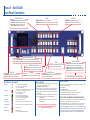
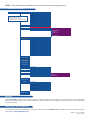
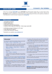
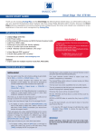
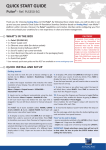
Eikos LE - EKS400
QUICK START
Thank you for choosing Analog Way and the Eikos LE. By following these simple steps, you will be able to setup
and use your powerful Multi Layer Hi-Res. Mixer Seamless Switcher within minutes. Discover the Eikos LE extensive
capabilities and intuitive interface while configuring your first show, and unleash your creativity for a new experience in
show and event management by Analog Way.
What’s in the box
1 x Eikos LE (EKS400)
1 x Power supply cord
2 x DVI male to HD15 female and DVI-D female breakout cable
1 x HD15 to 5 BNC cable
1 x Ethernet cross cable (for device update)
1 x Set of 11 audio 5-pin screw terminals
4 x Screws for handle removal (M4x12mm)
1 x RCS - Remote Control Software (PC only) *
1 x Quick Start Guide (PDF version) *
1 x User Manual (PDF version) *
WARNING !
If required, front handles of the device can be dismantled,
but with caution.
The original screws removed must not be reintroduced to
their location without handles in place.
Substantial damages can occur, including risk of electric shock from the mains voltage.
Only M4x12mm screws can be used.
(They are supplied with the unit)
* Download on our website: www.analogway.com
Quick install and setup
Key points:
• Red LED: Source or layer is on Main
• Blinking button: Source or layer selected for modification
• DSK function uses a layer
• Frames and Logos are unscaled sources
• One logo available in Native Matrix Mode per output
• BLACK button allows to remove a Layer (Clear
function)
IN MIXER MODE (Maximum displaying):
- 1 Background Live Seamless in switching
- 2 PIPs on Background Live + 2 Logos
- 3 PIPs on Background Frame + 2 Logos
IN NATIVE MATRIX MODE:
- 1 PIP on Background Frame + 1 Logo
- No preview
Getting started:
1. Observe all safety precautions. Rackmount chassis
(please refer to user’s manual) or install in «table
top» configuration.
2. Connect all inputs (please refer to user’s manual:
Input specification).
3. Power on.
4. Perform factory reset:
• Press the Exit/Menu button, from the Home
Menu
• Select [Control] > navigate in the Menu by
rotating the corresponding knob
• Press the Enter button or push the knob to
enter the control sub-menu
• Select [Default Values] and press Enter
button. This operation should take approximately
30 seconds.
IMPORTANT: simply selecting a menu item will not
set it to that value. Be sure to press the ENTER button
when parametering the menu items.
Eikos LE - Ref. EKS400
Front Panel Description
LAYER
LAYER SELECTION
FUNCTION
BLACK: Change the active layer to Black
FREEZE: Freeze the input linked to the current layer on MAIN
Background Frame: Display or change Frame
Background Live/PIP1: Change active Layer
PIP2 to PIP3: Change active layer to a PIP
Logo1 to Logo2: Display or change Logo
PREVIEW: Toggle preview functionality
SHIFT: Secondary function selection button
Analog Input Selection
#1-7 L / F #1 to #7: access source #1 to #7, Display Frame or Logo #1 to #7
#8 AL / F #8: access Source #8, Display Frame #8 or Logo #8 or Animated Logo
Transition the pre-selected sources onto the
MAIN output with the selected effects
Digital Input Selection
DVI
1 to DVI 2: Press to access DVI #1 or DVI #2
SDI 1 to SDI 4: Press to access SDI #1 to SDI #4
CONTROL
STAND-BY: Hold for 3 seconds for stand-by Mode
BUTTON COLOR USAGE
No light: Dim green: #1 = Input not available on autolock
#2 = Frame or Logo not available
#3 = Layer not available
#4 = Button not available depending on the user mode
#1 = Source, Layer or Window is on Main
#2 = Mosaic Preview enable
#3 = Freeze enable
#1 = Source or Layer is on Preview
#2 = Function available for modification
#3 = Current output on Matrix Mode
Button available for selection
Blinking red: Active Layer or Source for modification on Main
Blinking green: Active Layer or Source for modification on Preview
Dim red: Solid orange: Stand-by button
Solid red:
Solid green: MATRIX #1 & #2
STAND-BY
EXIT/MENU: Home Menu or back one level
ENTER: Validates the menu or command
#1 = Shift button
#2 = Function available by Shift button
Effect / Preset
TAKE
OUTPUT #1 to #2: select the output #1 to #2, a layer
and a source, then press TAKE
INPUT SETUP
1- Press the EXIT/MENU button from the Home menu [all functions
must be confirmed by the Enter button]
2- Press [Input] and [Autoset ALL]
3- If the acquisition is successful the source appears on Preview.
Please Toggle the Preview button to display the Mosaic Mode
4- If the acquisition has failed, check all connections and perform a
manual setup
5- For a comprehensive Input Setup, please refer to user’s Manual
6- For a manual input setup, press the EXIT/MENU button:
a) Press [Input],
b) Select the right input from Input #1 up to SDI #4, then
c) Select [Type].
NOTE: To adjust input Size or Pos, use the [Layer] Menus.
To adjust Blanking, use the Auto-Centering or Blanking
adjustments in the Image menu.
Preset section: Stores and recalls 4 presets available
CUT: Select Cut as the current transition type
FADE: Select Fade as the current transition type
USER #1: Select User #1 as a customized transition
USER #2: Select User #2 as a customized transition
P#1-4: Select P #1 to #4 as a customized preset
OUTPUT SETUP
1- Press the EXIT/Menu button from the Home menu [all functions must be
confirmed by the Enter button]
2- Press [Output]
3- Press [Output format]
4- On Format line, select the display’s native resolution
5- Control or adjust your display device (Monitor or Video Projector)
6- If necessary, select [Test Pattern] in the Output menu
HOW TO USE THE MOSAIC PREVIEW FEATURE
To have a full vision of the aspects of your inputs two modes are available. When
the Mosaic Preview button is activated (Red light solid button):
- One live source mode: select your Layer and the source you want to put on it.
The input selected will be automatically refreshed on your Mosaic Preview
Press a Layer button (Bkgnd Live, PIP1 or 2) --> Press the Live souce chosen
- Random live source mode: To have a random refreshment of all your inputs, select
a layer and put it to black. All sources will be automatically refreshed randomly.
Press a Layer button (Bkgnd Live, PIP1 or 2) --> Press the Black Button
Eikos LE - Ref. EKS400
Rear Panel Description
IP-LAN connector
AUDIO INPUT
Balanced or unbalanced mono/stereo inputs
(all pin MCO male connectors)
Universal Analog Computer/TV/HDTV inputs
RS-232 communication port
on a DB9 female connector or
TCP/IP on RJ45 connector
SD-SDI/HD-SDI inputs #1 to #4: female BNC
Power supply: IEC/EN/UL/CSA
60950-1, internal, autoswitchable
O P E R AT I O N S O V E R V I E W
WORKING IN MIXER MODE
1- Select an input.
2- On the preview screen, the input appears
3- Select an EFFECT (open/close)
4- Press TAKE to view the result on the Main screen
WORKING WITH PIPs IN MIXER MODE
1- Press the PIP2 button. On the preview screen, the PIP (layer) appears as a
color rectangle
2- Select an input. On the preview screen, the input appears in the layer rectangle
3- Adjust the PIP (layer) with ADJUSTMENT button (Pos & Size or Zoom by
Toggle function)
4- Select a transition (open/close) or an effect into Layer menu [Home menu]
5- Press TAKE to view the result on the main screen
6- To remove layer, press BLACK then TAKE
7- For another PIP setup, repeat from step #1
DVI inputs #1 & #2: female DVI-I (digital pins)
Outputs #1 (Main) & #2 (Preview): female
HD15, DVI-I (analog pins)
VIDEO OUT
Connectors:
1x BNC-F: SD/HD-SDI (with audio embedded)
3x BNC-F: Y_Cb_Cr
1x Mini Din 4: S. Video
1x BNC-F: Composite video PAL/NTSC
AUDIO OUTPUT
Balanced or unbalanced mono/
stereo Output
(all Pin MCO mode connector)
HOME MENU
AUDIO CONNECTIONS
- MODE : select to choose which mode the Eikos LE will work in (Mixer or Matrix Mode).
- INPUT : select to configure the 12 individual input types and resolutions.
- MAIN OUT : in Mixer mode, select to set the output types and resolutions of the Main output.
- OUTPUT 1 : in Matrix mode, select to set the output types and resolutions of Output 1.
- PREVIEW OUT : in Mixer mode, select to set the output types and resolutions of the Preview output.
- OUTPUT 2 : in Matrix mode, select to set the output types and resolutions of Output 2.
- VIDEO OUT : select to configure Video output card settings.
- PRESET : select to store and use presets.
- IMAGE : select to change source image settings of an input.
- KEYING/TITLING : select to access keying and titling controls and parameters when video layer
is selected.
- LAYER : select to adjust layer size, position, border, transparency or transitions.
- LOGO/FRAME : select to store (record), use and manage logos and frames into the Eikos LE.
- AUDIO : select to access all audio input and output parameters.
- CONTROL : select to access device software information, LAN settings, reset factory settings,
amongst other user oriented functions (see next page).
- VIRTUAL T-Bar : select to access the Virtual T-Bar.
MCO male connectors
Inputs #1 to #6: Balanced & unbalanced connection
Inputs DVI #1 to DVI #2: Balanced &unbalanced connection
Input (AUX): Balanced & unbalanced connection
Outputs #1 to #2: Balanced &unbalanced connection
NOTE : The updater files are available on our web site: http://www.analogway.com
Home Menu (extract)
CONTROL
Versions
Vers.: 3.00 BETA
l1=xxxx l2=xxxx
l3=xxxx l4=xxxx
0=xxxx
MM K=xxxx
MF K=xxxx
CA V=xxxx
FA V=xxxx
TH V=xxxx
CS V=xxxx
(L1) UDP only
(L2) Confirmation asked
(L3) Only for User 1 & User 2
(L4) Visible if Sync. Loss is activated
RS232/LAN
RS232
LAN
LAN setup
TCP
UDP
Sync. loss
Enabled
Input 1 (L4)
Input 2 (L4)
Input 3 (L4)
Input 4 (L4)
Input 5 (L4)
Input 6 (L4)
DVI 1 (L4)
DVI 2 (L4)
SDI 1 (L4)
SDI 2 (L4)
SDI 3 (L4)
SDI 4 (L4)
Device address...
Remote address (L1)
Gateway address...
Device port...
Remote port (L1)
Netmask...
Default setup (L2)
Auto lock
Auto take
Preset toggle
V-TBar enable
Transp Backgr
Dynamic fit
Freeze mode
Input freeze
Freeze all
Key locking
All
Menus
Prog. Keys
Fade
User 1
User 2
Type (L3)
Direction (L3)
Effect duration
LCD brightness
Key brightness
Standby
Baud rate
Set message ON
Set message OFF
Clear message ON
Clear message OFF
Standby
Erase Memories (L3)
Default values
(L3)
Warranty
This Analog Way product has a 3 year warranty on parts and labor, return to factory. This warranty does not include faults
resulting from user negligence, special modifications, electrical surges, mishandling (drop/crush), and/or any other damage
caused by misuse.
Going further with the EIKOS LE
For complete details and operations procedures, please refer to the Eikos LE User’s Manual and our website for further
information: www.analogway.com
Version : 4.0 - 27/12/2011
Code : 140121