1
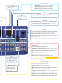
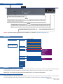
RK-300 - Ref. RK-300
QUICK START GUIDE
Thank you for choosing Analog Way and the RK-300. By following these simple steps, you should be able to setup
and use your powerful remote Control Keypad within minutes. Discover the RK-300 extensive capabilities and intuitive
interface while configuring your first show, and unleash your creativity for a new experience in show and event
management by Analog Way.
What’s in the box
1 x RK-300 (RK-300)
1 x Power supply Cord
1 x DB9 (M/F) Cable
1 x Carrying Case
1 x Quick Start Guide *
* Download on our website: http://www.analogway.com
RK-300 settings
• The RK-300 automatically detects the right versions of the product to control. Connect the DB9 cable
supplied or an Ethernet crossover cable using the
same protocol as the unit connected.
Pressing the [ENTER] button when a selection has been
made sets the value to that selection in the RK-300
memory. When all settings have been made, press the
[EXIT/MENU] button to exit sub-menus and return to the
main menu.
• To control the following Seamless Switchers:
Control
Mode
Seamless
Mixer
Seamless
Matrix
Quadravision
EKS500
x
x (1)
x
x
EKS400
x
OPS300
x
OPS200
x
PLS300
x
PLS200
x
SVU300
x
SVU200
x
(1)
x
SMX100
x
SMX200
x (1)
STE100
SQD200
Soft Edge
Blending
x
x
We recommend using the Advanced Seamless Matrix Mode with
an ORCHESTRA or a Remote Control Software (RCS).
IMPORTANT: simply selecting a menu item will not set it
to that value. Be sure to press the [ENTER] button when
parametering the menu items.
Once you have connected your RK-300 to your switcher,
configure the connection settings on both devices. For a serial connection, select RS232 from the RS232/
LAN menu on both devices.
For a LAN connection, select LAN from the RS232/LAN
menu on both devices, and configure each device with
a unique IP in the LAN setup -> RK-300 address menu. The default IP on the RK-300 is 192.168.0.15. Next,
enter the IP of the device you wish to control in the Lan
Setup -> Device address menu.
Once your settings are correct, the RK-300 will begin to
synchronize with the device, and you will be ready to begin.
(1)
Navigation Menu:
To access the RK-300 menu, press the [EXIT/MENU]
button in the control section. To highlight items in the
menu which will appear on the VFD screen, turn the
scroll knob left or right to the desired menu item. When
you have reached the desired menu item, press the
[ENTER] button in the control section to access that
menu function.
Button Color Usage:
Solid red:
#1 = Source is on the main outputs
#2 = Freeze enable
#3 = Stand-by button
#4 = Preset Selection
Solid green: #1 = Source is on Preview
#2 = Function available for modification
Solid orange:
Blinking red: Unlocked sources
Blinking green: Layer/source selected, and is not currently
active one the main output
Layer/source selected, and is currently
active on the main output
WORKING WITH THE RK-300
Front Panel Description
Exit/Menu
Switch between Status & Control Mode.
PREVIEW
Toggle Standard or Mosaic mode
when available.
Layer
BACKGROUND/FRAME: Select the Frame Layer.
BACKGROUND LIVE/ PIP 1: Select the Live Layer/PIP1.
PIP 2: Select the PIP2 live Layer.
PIP 3: Select the PIP3 live Layer.
LOGO 1: Select the Logo 1 Layer.
LOGO 2: Select the Logo 2 Layer.
DSK: Shortcut to the Keying/Titling menu for the selected source.
Input
#1 L/ F 1: Press to access source #1, Frame #1 or Logo #1.
#2 L/ F 2: Press to access source #2, Frame #2 or Logo #2.
#3 L/ F 3: Press to access source #3, Frame #3 or Logo #3.
#4 L/ F 4: Press to access source #4, Frame #4 or Logo #4.
#5 L/ F 5: Press to access source #5, Frame #5 or Logo #5.
#6 L/ F 6: Press to access source #6, Frame #6 or Logo #6.
#7 L/ F 7: Press to access source #7, Frame #7 or Logo #7.
#8 AL/ F 8: Press to access source #8, Frame #8 or Logo #8 or Animated Logo.
DVI 1 to DVI 2: Press to access DVI #1 or DVI #2.
SDI 1 to SDI 4: Press to access SDI #1,2,3 or 4.
BLACK: Change the active layer to Black to clear a layer or PIP.
FREEZE: Freeze the input linked to the current layer on MAIN.
SHIFT
SHIFT: Secondary function selection button.
MATRIX
OUTPUT #1: Press to select the Output #1, select a layer and a source then press [TAKE].
OUTPUT #2: Press to select the Output #2, select a layer and a source then press [TAKE].
Quadravision
Control
Available when controling a device which offers
Quadravision.
W1: Change the active layer into the Window #1.
W2: Change the active layer into the Window #2.
W3: Change the active layer into the Window #3.
Allow to scroll through the
different menus
ENTER
T-Bar
ENTER button validates a selected item.
Mini T-Bar to control
effect level.
POSITION
Easy adjustments (size or position) with this mini joystick. Adjust
the selected PIP or Logo, X-Axis (Left/Right), Y-Axis (Up/Down)
and click to change the mode (position or size).
VOLUME
VOL: Volume adjustment of the MAIN output (adjust with the knob ◄ ►).
Button is blinking during the adjustment. This function will be dismissed after 2 seconds delay or after pushing [ENTER] button.
MUTE: Toggles the audio mute of the Main output. Button illuminates
when volume is muted.
Adjustment
Adjust Sources:
TAKE
Press on [TAKE] allows
to display the preselected sources onto
the MAIN output with
the selected effects.
Chose the selected source Aspect Out as:
1:1: No scaling, layer size has no effect
CENTERING*: Centered (aspect ratio preserved, black bars around source)
FULL*: Fullscreen (aspect ratio distorted, black bars around source)
CROP*: Cropped (aspect ratio preserved, extra image cropped
---ZOOM: Configures the Layer Zoom
---SIZE: Resize the active layer with the mini joystick
POS: Adjust PIP Layer or Logo Position with the mini joystick
* accessible via the Shift Key
EFFECT/PRESET
CUT: Select Cut as the current transition type.
TOGGLE PRESET
Allow to copy the previous Current Preset in
the Next Preset at the
end of a [TAKE].
FADE: Select Fade as the current transition type.
USER 1: Selects the customized transition configured in the Control menu.
USER 2: Select User #2 as a customized transition.
Preset section: Recalls stored presets from the device. Store presets
using Menu -> Preset-> Store Preset.
P1/P5: Select P #1 as a customized preset or P #5 by shift function.
P2/P6: Select P #2 as a customized preset or P #6 by shift function.
P3/P7: Select P #3 as a customized preset or P #7 by shift function.
P4/P8: Select P #4 as a customized preset or P #8 by shift function.
Rear Panel Description
Allow to secure with a KensingtonTM Lock.
RJ-45
RJ-45 Connector: Connect the RK-300 to a 10/100 BT Ethernet LAN using this female RJ-45
connector: used to control the switcher and also to upgrade the RK-300. Please see the updater
software instructions for more information.
RS-232
RS-232 PORT: This 9-pin Female D connector provides RS-232 port serial communication with the
switcher and also to upgrade the RK-300. A DB9 F/F crossover cable (not supplied) is required for an
RS232 update. This port can also provide power to operate the RK-300 when connected to a switcher.
DC
DC Power connector: Plug a Jack coaxial 5.5 - 2.1 - 9mm - external GND. 9/12 Vdc - 1A.
NOTE: The latest firmware upgrade is always available on our website: http://www.analogway.com
Menu Tree
RK-300 CONTROL
(L1) UDP only
(L2) Confirmation asked
(L3) Only for User1& User2
Versions
Version: 1.00 BETA
Boot: 1.00 BETA
I1=xxxx I2=xxxx
I3=xxxx I4=xxxx
O=0000
CS1=xxxx
CS2=xxxx
CS3=xxxx
RS232/LAN
RS232
LAN
LAN setup
TCP
UDP
Key locking
All
Menus
Prog. keys
Fade
User 1
User 2
RK-300 address...
Remote address...
Gateway address...
RK-300 port...
Remote port... (L1)
Netmask...
Default setup... (L2)
Type (L3)
Direction (L3)
Effect duration
LCD brightness
Key brightness
Standby
Default values (L2)
LAN Update
Warranty
All Analog Way products have a 3 year warranty on parts and labor, back to factory, but do not include faults resulting from
user negligence, special modifications, electrical surges, abuse (drop/crush), and/or other unusual damage.
Please note: The included carrying case and protective foam is not covered under warranty.
Going further with the RK-300
The RK300 allows for remote control of all available device features. Please check your device manual for more information
on device operation and usage. Please check our website for further information: www.analogway.com
Version : 3.60 - 14/09/11 - M3.0
Code : 140116