1
NETWORK GATEWAY SERIES
ICC
INDUSTRIAL CONTROL COMMUNICATIONS, INC.
ICC
INDUSTRIAL CONTROL COMMUNICATIONS, INC.
Madison Office
1600 Aspen Commons, Suite 210
Middleton, WI USA 53562-4720
Tel: [608] 831-1255 Fax: [608] 831-2045
http://www.iccdesigns.com
MBP-100
Houston Office
12300 Dundee Court, Suite 212
Cypress, TX USA 77429-8364
MODBUS PLUS
MULTIPROTOCOL NETWORK GATEWAY
Printed in U.S.A
August 2008
ICC #10498-3.100-001
Introduction
Thank you for purchasing the ICC MBP-100 Modbus Plus Multiprotocol
Network Gateway. The MBP-100 allows information to be transferred
seamlessly among many different fieldbus networks with minimal configuration
requirements. The MBP-100 provides one Modbus Plus port, one RS485 port,
one RS232 port, and three common serial ports for direct connectivity to
Toshiba 7-series, 9-series, 11-series or VF-nC1 Adjustable Speed Drives
(ASDs). These various communication ports operate independently, and are
configurable along with the unit’s internal point database via a serial console
interface.
The gateway currently provides support for the following protocols:
Modbus RTU (RS485 master & slave)
Modbus RTU (RS232 master & slave)
Toshiba ASD (common serial master)
Toshiba ASD (RS485 master)
Mitsubishi 500-series & 700-series ASD (RS485 master)
Modbus Plus (host)
New network drivers are continuously being added, and can be downloaded for
free from our web site.
Before using the MBP-100 network gateway, please familiarize yourself with the
product and be sure to thoroughly read the instructions and precautions
contained in this manual. In addition, please make sure that this instruction
manual is delivered to the end user of the MBP-100, and keep this instruction
manual in a safe place for future reference or unit inspection.
This instruction manual describes the device specifications, wiring methods,
maintenance procedures, supported functions, usage methods and firmware
update procedure for the MBP-100 network gateway.
For the latest information, support, firmware releases or product configuration
files, please visit http://www.iccdesigns.com.
Before continuing, please take a moment to ensure that you have received all
materials shipped with your kit. These items are:
•
•
•
MBP-100 gateway
2 meter DB9-RJ45 RS232 port cable (part number 10425)
Documentation CD-ROM
MODBUS PLUS IS A REGISTERED TRADEMARK OF SCHNEIDER ELECTRIC
1
MBP-100 Modbus Plus Multiprotocol Network Gateway
User's Manual
Part Number 10498-3.100-001
Printed in U.S.A.
©2008 Industrial Control Communications, Inc.
All rights reserved
Industrial Control Communications, Inc. reserves the right to make changes
and improvements to its products without providing notice.
Notice to Users
INDUSTRIAL CONTROL COMMUNICATIONS, INC.’S PRODUCTS ARE NOT
AUTHORIZED FOR USE AS CRITICAL COMPONENTS IN LIFE-SUPPORT
DEVICES OR SYSTEMS. Life-support devices or systems are devices or
systems intended to sustain life, and whose failure to perform, when properly
used in accordance with instructions for use provided in the labeling and user's
manual, can be reasonably expected to result in significant injury.
No complex software or hardware system is perfect. Bugs may always be
present in a system of any size. In order to prevent danger to life or property, it
is the responsibility of the system designer to incorporate redundant protective
mechanisms appropriate to the risk involved.
2
Usage Precautions
Operating Environment
•
Please use the gateway only when the ambient temperature of the
environment into which the unit is installed is within the following
specified temperature limits:
Operation: -10 ∼ +50°C (+14 ∼ +122°F)
-40 ∼ +85°C (-40 ∼ +185°F)
Storage:
•
Avoid installation locations that may be subjected to large shocks or
vibrations.
Avoid installation locations that may be subjected to rapid changes in
temperature or humidity.
•
Installation and Wiring
•
•
Proper ground connections are vital for both safety and signal reliability
reasons. Ensure that all electrical equipment is properly grounded.
Route all communication cables separate from high-voltage or noiseemitting cabling (such as ASD input/output power wiring).
ASD Connections
•
•
•
•
•
•
Do not touch charged parts of the drive such as the terminal block
while the drive’s CHARGE lamp is lit. A charge will still be present in
the drive’s internal electrolytic capacitors, and therefore touching these
areas may result in an electrical shock. Always turn all drive input
power supplies OFF, and wait at least 5 minutes after the CHARGE
lamp has gone out before connecting communication cables.
To avoid misoperation, do not connect any gateway terminals to either
the ASD’s E/GND terminals, the motor, or to any other power ground.
When making common serial connections between the gateway and
Toshiba ASDs, do not use cables that exceed 5 meters in length.
For further drive-specific precaution, safety and installation information,
please refer to the appropriate documentation supplied with your drive.
Internal ASD EEPROMs have a limited life span of write cycles.
Observe all precautions contained in this manual and your ASD
manual regarding which drive registers safely may and may not be
repetitively written to.
When used without an Auxiliary power source (Toshiba ASD common
serial mode), the gateway derives its control power from the connected
drives. Therefore, removing power to all connected drives will also
cause the gateway to lose power.
3
TABLE OF CONTENTS
1.
The Network Gateway Series Concept.......................................6
2.
Mechanical Diagrams ...................................................................7
2.1
2.2
2.3
Enclosure ..............................................................................................7
Mounting Clip ........................................................................................8
External Interface ..................................................................................9
3.
Feature Summary........................................................................11
4.
Installing the Gateway................................................................14
4.1
RS-485 Network in Use.......................................................................14
4.2
Toshiba ASD (Common Serial) Network in Use ..................................15
4.2.1 Installation for G7 ASDs..................................................................15
4.2.2 Installation for S7, S9, S11, A7 and VF-nC1 ASDs.........................17
5.
RS485 Port Electrical Interfaces ...............................................19
6.
Environmental Specifications ...................................................20
7.
Maintenance and Inspection .....................................................21
8.
Storage and Warranty ................................................................22
8.1
8.2
9.
Storage................................................................................................22
Warranty..............................................................................................22
LED Indicators ............................................................................23
9.1
9.2
Toshiba ASD Common Serial Port Indicators .....................................23
RS232 (MMI) Port Indicators...............................................................23
10.
Configuration Switches .........................................................24
11.
Auxiliary Power Supply..........................................................25
12.
Unit Configuration Concepts.................................................26
12.1
12.2
12.3
12.4
Port and Protocol Configuration ..........................................................26
Timeout Configuration .........................................................................26
Point Configuration..............................................................................27
General Configuration Procedure........................................................28
13.
Console Access ......................................................................30
13.1
RS232 .................................................................................................30
13.1.1
Requirements .............................................................................30
13.1.2
Connection .................................................................................30
4
13.1.3
Application Configuration ........................................................... 30
13.2
Invocation ........................................................................................... 33
13.3
Main Menu.......................................................................................... 34
13.3.1
View/Edit Points ......................................................................... 35
13.3.2
View/Edit Ports .......................................................................... 44
13.3.3
Load Points................................................................................ 46
13.3.4
Xmodem Point File..................................................................... 46
13.3.5
MBP-100 Information ................................................................. 48
14.
Protocol-Specific Information ...............................................49
14.1
Modbus............................................................................................... 49
14.1.1
Coil & Discrete Input Mappings.................................................. 50
14.1.2
Modbus RTU Slave.................................................................... 51
14.1.3
Modbus RTU Master.................................................................. 51
14.2
Modbus Plus....................................................................................... 53
14.3
Toshiba Common Serial ASD Protocol............................................... 54
14.4
Toshiba RS485 ASD Protocol ............................................................ 54
14.5
Mitsubishi ASD Protocol ..................................................................... 57
14.6
Teco-Westinghouse ASDs.................................................................. 61
14.6.1
MA7200 ..................................................................................... 61
14.6.2
PA7300 ...................................................................................... 62
15.
Modicon PLC Programming Examples.................................64
15.1
Ladder Logic and MSTR Instructions.................................................. 64
15.1.1
MSTR Parameters ..................................................................... 65
15.1.2
MSTR Inputs and Outputs ......................................................... 66
15.2
MSTR Function Error Codes .............................................................. 66
15.3
MSTR Read Example ......................................................................... 66
15.4
MSTR Write Example ......................................................................... 67
15.5
MSTR Global Read Example.............................................................. 68
15.6
MSTR Global Write Example.............................................................. 69
16.
Firmware Updates...................................................................70
16.1
Requirements ..................................................................................... 70
16.2
Connection ......................................................................................... 70
16.3
Using the RFU Utility .......................................................................... 71
16.3.1
Required Files............................................................................ 71
16.3.2
First-Time Configuration ............................................................ 71
16.3.3
Transmitting Firmware Files....................................................... 73
16.4
Wrap-Up ............................................................................................. 74
5
1. The Network Gateway Series Concept
The MBP-100 is a member of the ICC Network Gateway Series product family.
Members of this family are designed to provide a uniform interface,
configuration and application experience. This commonality reduces the user’s
learning curve, reducing commissioning time while simplifying support. The
MBP-100 provides simultaneous support for many different communication
protocols, allowing complex interchanges of data among otherwise
incompatible networks.
The heart of the Network Gateway Series concept is an element called the
“point database”. The point database is entirely user-configurable, and
provides the mapping information that allows requests from the various
supported networks to be interpreted and stored in a common format. This
allows data to be routed from any supported network to any other supported
network.
Additionally, the point database provides the added benefit of “data mirroring”,
whereby current copies of point values (populated by a “source port”
designation) are maintained locally within the gateway itself. This greatly
reduces the request-to-response latency times on the various networks, as
requests (read or write) can be entirely serviced locally, thereby eliminating the
time required to execute a secondary transaction on a different network.
When properly configured, the gateway will become essentially “transparent” on
the networks, and the various network devices can engage in seamless dialogs
with each other.
6
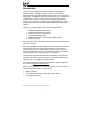
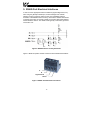
2. Mechanical Diagrams
2.1 Enclosure
Figure 1: Enclosure Dimensions (units are inches)
7
2.2 Mounting Clip
Figure 2: Mounting Clip Dimensions (units are inches)
8
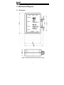
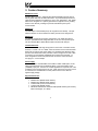
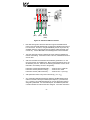
2.3 External Interface
Modbus Plus
Network
Chassis
GND
Figure 3: Bottom View
Reserved
Modbus Plus
Status LED
MMI (RS232)
port
Modbus Plus Node
Address Switches
RS485
port
AUX Power
Figure 4: Front View
9
Data Write
LEDs
ASD #3 ASD #2
ASD #1
Figure 5: Top View
10
ASD Link
LEDs
3. Feature Summary
Modbus Plus Port
Standard DB9 connector. Supports both standard (MSTR) read and write as
well as global data read and write instructions. Any internal data point has the
option of being mapped to the gateway’s “get” or “put” global data. “Get” global
data can be configured on a point-by-point basis to originate from any existing
device on the network, providing for powerful and efficient peer-to-peer
communication.
RS485 Port
One half-duplex 2-wire RS485 port (A / B / Signal Ground / Shield). This port
allows a selection of various master and slave protocols to be assigned to it.
RS232 Port
One RS232 port that can be used to configure the unit, update the internal
firmware, upload/download configuration files or act as a control protocol port.
Use the included DB9-to-RJ45 RS232 cable to interface with this port.
Toshiba ASD Ports
Three common serial (aka logic level) ports for connection of Toshiba 7-series,
9-series, 11-series or VF-nC1 ASDs. ASD connections use the same standard
RJ45 style 8-conductor UTP patch cables: any standard CAT5 Ethernet cable
(found in most electronics stores) 5 meters or less in length can be used. ASD
connections are automatically established and continuously monitored: no
drive configuration needs to be performed to connect the unit to the drives.
Just plug it in – it’s that simple.
Power Supply
When connected to Toshiba ASDs via the ASD1 / ASD2 / ASD3 ports, can be
either powered directly from the attached ASDs, or from the auxiliary power
(“POWER”) input jack. All other non-Toshiba applications require the use of the
“POWER” input to supply power to the unit. When more than one power source
is connected, the unit will draw its control power from the source with the
highest supply voltage.
Supported Protocols
Modbus Plus
Modbus RTU (RS485 master & slave)
Modbus RTU (RS232 master & slave)
Toshiba ASD (common serial master)
Toshiba ASD (RS485 master)
Mitsubishi 500-series & 700-series ASD (RS485 master) (also used by
MGI Technologies, Inc. ASDs)
11
New network drivers are continuously being added, and can be downloaded for
free from our web site.
Text-Based Console Configuration
Unit configuration is performed via a text-based console interface, available
locally over the RS232 port via a standard PC terminal program such as
Microsoft Windows HyperTerminal®.
Configuration File Upload/Download
A unit’s configuration can be uploaded from / downloaded to a PC, which
provides the capability for PC-based file backup and easy configuration copying
to multiple units. Pending availability, sample configuration files and related
documentation may also be downloaded from our web site, uploaded to a unit,
and custom-modified to suit a specific application.
Network Timeout Action
A per-port and per-point 2-level configurable network timeout action can be
programmed that allows each internal point to have its own unique “fail-safe”
condition in the event of a network interruption.
Indicators
2 green LEDs exist on each of the ASD ports and on the RS232 port connector.
Refer to section 9 for more detailed information about the LED indicators and
their meanings.
Field-Upgradeable
As new firmware becomes available, the unit can be upgraded in the field by
the end-user. Refer to section 16 for more information.
Versatile 3-Way DIN-Rail Mounting System
The unit’s enclosure is provided with a mounting clip attached to the rear of the
unit. This clip allows the unit to be mounted 3 different ways:
•
For DIN rail mounting, snap the mounting clip onto a standard DIN rail,
and then snap the unit enclosure onto the clip’s retaining tabs. This
allows easy removal or repositioning of the unit on the DIN rail during
wiring.
•
For panel mounting, the mounting clip can be bolted directly to a flat
panel via the two bolt holes at the top and bottom of the clip. Refer to
section 2.2 for mounting clip mechanical details. Once the mounting
clip is securely attached to the panel, the unit enclosure can be
snapped onto the clip’s retaining tabs.
•
For fixed DIN rail mounting, a combination of the above two
techniques can be employed. First, snap the mounting clip onto a DIN
rail and position it in its desired location. Then, the mounting clip can
be bolted to the DIN rail support panel, securing it in place. Lastly, the
unit can be snapped onto the fixed mounting clip.
12
In all cases, the unit can be easily unsnapped from the mounting clip to
temporarily provide easier access to the chassis ground terminal or network
connector.
13
4. Installing the Gateway
The gateway’s installation procedure will vary slightly depending on the chosen
mounting method and the networks that will be used.
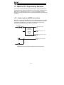
4.1 RS-485 Network in Use
Note that in order to power the unit when not connecting to Toshiba ASDs via
the common serial ports, the optional 120VAC/9VDC power supply (ICC part
number 10456) or a user-supplied power source meeting the requirements
outlined in section 11 must also be installed.
1.
Mount the unit via the desired method (refer to page 12 for more
information).
2.
Connect the Modbus Plus network to the “NETWORK” DB9 connector. Be
sure to follow all published guidelines pertaining to Modbus Plus network
connections, layout and routing.
3.
Connect the RS485 network to the pluggable terminal block. Refer to
section 5 for detailed connection information. Ensure that the terminal
block is fully seated into the terminal block header, and route the network
cable such that it is located well away from any electrical noise sources,
such as ASD input power or motor wiring. Also take care to route the
cable away from any sharp edges or positions where it may be pinched.
4.
Take a moment to verify that the gateway and all network cables have
sufficient clearance from electrical noise sources such as drives, motors, or
power-carrying electrical wiring.
5.
Connect the power supply to the gateway’s “POWER” jack.
14
4.2 Toshiba ASD (Common Serial) Network in Use
The gateway connects to each drive via the drive’s common serial (logic level)
communication port, typically located on either the main drive control board
(G7, S11), on the front of the drive enclosure under a small snap-on cover (A7,
S9), on the right-hand side of the drive enclosure under a small snap-on cover
(S7), or on the bottom side of the drive enclosure (VF-nC1). Although in
general no drive parameters need to be configured in order to use the gateway,
it is advantageous to check that the drive’s common serial communication data
rate is set to its maximum speed. Because the gateway will communicate to
each drive only at the drive’s configured data rate, this will provide the fastest
response time for drive-to-network data transfers. For information on checking
the drive’s common serial communication data rate, refer to the appropriate
manual supplied with your drive.
Note that the common serial communication parameters of each drive are
handled independently by the gateway, which means that different drive
families may be connected to different channels of the unit in any combination,
and that the drives connected to each channel may simultaneously
communicate to the unit at completely different baud rates, parity settings, etc.
Drives can be connected to the gateway on any ASD channel in any order or
combination. When more than one drive is connected to the unit, or if the
optional auxiliary power supply is used, the gateway will draw its control power
from the source with the highest power supply voltage.
Installation of the gateway should only be performed by a qualified technician
familiar with the maintenance and operation of the connected drives. To install
the gateway, complete the steps outlined in the following sections related to
your specific drive.
4.2.1 Installation for G7 ASDs
1.
Mount the unit via the desired method (refer to page 12 for more
information).
2.
CAUTION! Verify that all input power sources to the drives to
be connected have been turned OFF and are locked and tagged out.
3.
DANGER!
Wait at least 5 minutes for the drive’s
electrolytic capacitors to discharge before proceeding to the next step. Do
not touch any internal parts with power applied to the drive, or for at
least 5 minutes after power to the drive has been removed. A hazard
exists temporarily for electrical shock even if the source power has
been removed. Verify that the CHARGE LED has gone out before
continuing the installation process.
15
4.
Remove the drive’s front cover / open the drive’s cabinet door (refer to the
appropriate drive manual for instructions how to do this).
5.
The drive’s LCD panel (also called the “Electronic Operator Interface” or
“EOI”) can communicate with the drive via either the RS485/RS232
channel (CNU1/CNU1A) or the common serial channel (CNU2/CNU2A).
Because the gateway uses the common serial channel, the LCD panel
must be configured to use the RS485/RS232 channel. If the drive to be
connected is currently using CNU2 (on the drive control board) and
CNU2A (on the LCD panel), then this connection must first be switched
over to CNU1 (on the drive control board) and CNU1A (on the LCD panel).
Refer to Toshiba’s documentation for any precautions or notices regarding
this connection change. If the LCD panel is already connected via the
RS485/RS232 channel, then no change is required.
6.
Configure the drive’s LCD panel to communicate via the RS485/RS232
channel by setting parameter ”Communication Setting
Parameters...Communication Settings...Select LCD Port
Connection” to “RS485/232 serial”.
7.
Connect the drive’s common serial communication port (CNU2) to one of
the ASD channels of the gateway with the communication cable
(communication cable is not included with the gateway kit). When
choosing cables for this connection, standard 24 AWG category 5 (CAT5)
unshielded twisted-pair (UTP) 8-conductor cables found in Ethernet
networks in most office environments can be used. The maximum
allowable length for these cables is 5 meters. Although there are many
varieties and styles of CAT5 UTP cables available, ICC strongly
recommends using only high-quality cables from reputable manufacturers
to guarantee optimal noise immunity and cable longevity. Ensure that each
end of the cable is fully seated into the modular connectors, and route the
cable such that it is located well away from any drive input power or motor
wiring. Also take care to route the cable away from any sharp edges or
positions where it may be pinched.
8.
Reinstall the drive’s front cover / close the drive’s cabinet door.
9.
Repeat steps 2-8 to connect other drive(s) as needed.
10. Connect the Modbus Plus network to the “NETWORK” DB9 connector. Be
sure to follow all published guidelines pertaining to Modbus Plus network
connections, layout and routing.
11. If an auxiliary power supply is going to be used, connect it to the gateway’s
“POWER” jack.
12. Take a moment to verify that the gateway and all network cables have
sufficient clearance from drives, motors, or power-carrying electrical wiring.
13. Turn the power sources to all connected drives ON, and verify that the
drives function properly. If the drives do not appear to power up, or do not
function properly, immediately turn power OFF. Repeat steps 2 and 3 to
remove all power from the drives. Then, verify all connections. Contact
16
ICC or your local Toshiba representative for assistance if the problem
persists.
4.2.2 Installation for S7, S9, S11, A7 and VF-nC1 ASDs
1.
Mount the unit via the desired method (refer to page 12 for more
information).
2.
CAUTION! Verify that all input power sources to the drives to
be connected have been turned OFF and are locked and tagged out.
3.
DANGER!
Wait at least 5 minutes for the drive’s
electrolytic capacitors to discharge before proceeding to the next step. Do
not touch any internal parts with power applied to the drive, or for at
least 5 minutes after power to the drive has been removed. A hazard
exists temporarily for electrical shock even if the source power has
been removed. Verify that the CHARGE LED has gone out before
continuing the installation process.
4.
Remove the drive’s common serial communication port cover if it has one
(refer to the appropriate drive manual for instructions how to do this). Do
not discard this cover, as it should be reinstalled to minimize contamination
of the port’s electrical contacts if the gateway is ever disconnected from the
drive.
5.
Connect the drive’s common serial communication port to one of the ASD
channels of the gateway with the communication cable (communication
cable is not included with the gateway kit). When choosing cables for this
connection, standard 24 AWG category 5 (CAT5) unshielded twisted-pair
(UTP) 8-conductor cables found in Ethernet networks in most office
environments can be used. The maximum allowable length for these
cables is 5 meters. Although there are many varieties and styles of CAT5
UTP cables available, ICC strongly recommends using only high-quality
cables from reputable manufacturers to guarantee optimal noise immunity
and cable longevity. Ensure that each end of the cable is fully seated into
the modular connectors, and route the cable such that it is located well
away from any drive input power or motor wiring. Also take care to route
the cable away from any sharp edges or positions where it may be
pinched.
6.
Repeat steps 2-5 to connect other drive(s) as needed.
7.
Connect the Modbus Plus network to the “NETWORK” DB9 connector. Be
sure to follow all published guidelines pertaining to Modbus Plus network
connections, layout and routing.
8.
If an auxiliary power supply is going to be used, connect it to the gateway’s
“POWER” jack.
17
9.
Take a moment to verify that the gateway and all network cables have
sufficient clearance from drives, motors, or power-carrying electrical wiring.
10. Turn the power sources to all connected drives ON, and verify that the
drives function properly. If the drives do not appear to power up, or do not
function properly, immediately turn power OFF. Repeat steps 2 and 3 to
remove all power from the drives. Then, verify all connections. Contact
ICC or your local Toshiba representative for assistance if the problem
persists.
18
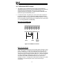
5. RS485 Port Electrical Interfaces
In order to ensure appropriate network conditions (signal voltage levels, etc.)
when using the gateway’s RS485 port, some knowledge of the network
interface circuitry is required. Refer to Figure 6 for a simplified network
schematic of the RS485 interface circuitry. Note that the “Shield” terminal has
no internal connection: its purpose is simply to provide a cable shield chaining
location between devices. The shield is then typically connected to ground at
one location only.
Figure 6: RS485 Interface Circuitry Schematic
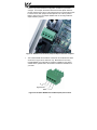
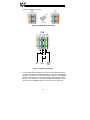
Figure 7 details the specific network connections to the RS485 terminal block.
A
B
Signal Ground
Shield
Figure 7: RS485 Terminal Block Connections
19
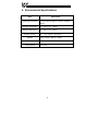
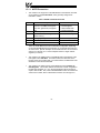
6. Environmental Specifications
Item
Specification
Operating Environment
Indoors, less than 1000m above sea level, do not
expose to direct sunlight or corrosive / explosive
gasses
Operating Temperature
-10 ∼ +50°C (+14 ∼ +122°F)
Storage Temperature
-40 ∼ +85°C (-40 ∼ +185°F)
Relative Humidity
20% ∼ 90% (without condensation)
Vibration
2
5.9m/s {0.6G} or less (10 ∼ 55Hz)
Grounding
Cooling Method
Non-isolated, referenced to power source ground
Self-cooled
20
7. Maintenance and Inspection
Preventive maintenance and inspection is required to maintain the gateway in
its optimal condition, and to ensure a long operational lifetime. Depending on
usage and operating conditions, perform a periodic inspection once every three
to six months. Before starting inspections, disconnect all power sources.
Inspection Points
•
Check that the network cable(s) are properly terminated in the terminal
block(s), and ensure that pluggable terminal blocks are fully seated in their
headers. Reseat if necessary.
•
Check that there are no defects in any attached wire terminal crimp points.
Visually check that the crimp points are not damaged or loose.
•
Visually check all wiring and cables for damage. Replace as necessary.
•
Clean off any accumulated dust and dirt.
•
If use of the gateway is discontinued for extended periods of time, apply
power at least once every two years and confirm that the unit still functions
properly.
•
Do not perform hi-pot tests on the gateway, as they may damage the unit.
Please pay close attention to all periodic inspection points and maintain a good
operating environment.
21
8. Storage and Warranty
8.1 Storage
Observe the following points when the gateway is not used immediately after
purchase or when it is not used for an extended period of time.
•
Avoid storing the unit in places that are hot or humid, or that contain large
quantities of dust or metallic dust. Store the unit in a well-ventilated
location.
•
When not using the unit for an extended period of time, apply power at
least once every two years and confirm that it still functions properly.
8.2 Warranty
The gateway is covered under warranty by ICC, Inc. for a period of 12 months
from the date of installation, but not to exceed 18 months from the date of
shipment from the factory. For further warranty or service information, please
contact Industrial Control Communications, Inc. or your local distributor.
22
9. LED Indicators
The gateway contains several different LED indicators, each of which conveys
important information about the status of the unit and connected networks.
These LEDs and their functions are summarized here.
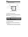
9.1 Toshiba ASD Common Serial Port Indicators
Each Toshiba ASD common serial port RJ45 connector contains two integrated
green LEDs. Figure 8 indicates the functions of these LEDs.
Data Write
Drive Link
Flashes briefly when data is
written to the drive from the
point database
Solid green when a logical
connection exists with the
attached drive
Figure 8: Toshiba Drive Connector Indicators
The Data Write indicator is useful for confirming that a specific drive is having
data written to it, while the Drive Link indicator provides an easy method of
determining that the gateway and drive are successfully exchanging data,
independent of any other network activity.
9.2 RS232 (MMI) Port Indicators
The RS232 port RJ45 connector also contains two integrated green LEDs.
Figure 9 indicates the functions of these LEDs.
Reserved
Modbus Plus Network
Status Indicator
Currently reserved for future
applications (always OFF)
Indicates Modbus Plus
network status/activity. Refer
to appropriate Modbus Plus
specifications for detailed
information.
Figure 9: RS232 Port Indicators
23
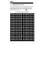
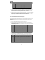
10. Configuration Switches
There are eight configuration DIP switches (marked “CONFIG”) located on the
front side of the gateway. Switches #1 - #6 set the Modbus Plus station
address of the gateway (refer to Table 1). Note that whenever the station
addressing switches (#1 - #6) are changed, power must be cycled to the
gateway to validate the change.
Table 1: Modbus Plus Station Addressing
SW1
SW2
SW3
SW4
SW5
SW6
Addr
SW1
SW2
SW3
SW4
SW5
SW6
Addr
ON
ON
ON
ON
ON
ON
1
ON
ON
ON
ON
ON
OFF
33
OFF
ON
ON
ON
ON
ON
2
OFF
ON
ON
ON
ON
OFF
34
ON
OFF
ON
ON
ON
ON
3
ON
OFF
ON
ON
ON
OFF
35
OFF
OFF
ON
ON
ON
ON
4
OFF
OFF
ON
ON
ON
OFF
36
ON
ON
OFF
ON
ON
ON
5
ON
ON
OFF
ON
ON
OFF
37
OFF
ON
OFF
ON
ON
ON
6
OFF
ON
OFF
ON
ON
OFF
38
ON
OFF
OFF
ON
ON
ON
7
ON
OFF
OFF
ON
ON
OFF
39
OFF
OFF
OFF
ON
ON
ON
8
OFF
OFF
OFF
ON
ON
OFF
40
ON
ON
ON
OFF
ON
ON
9
ON
ON
ON
OFF
ON
OFF
41
OFF
ON
ON
OFF
ON
ON
10
OFF
ON
ON
OFF
ON
OFF
42
ON
OFF
ON
OFF
ON
ON
11
ON
OFF
ON
OFF
ON
OFF
43
OFF
OFF
ON
OFF
ON
ON
12
OFF
OFF
ON
OFF
ON
OFF
44
ON
ON
OFF
OFF
ON
ON
13
ON
ON
OFF
OFF
ON
OFF
45
OFF
ON
OFF
OFF
ON
ON
14
OFF
ON
OFF
OFF
ON
OFF
46
ON
OFF
OFF
OFF
ON
ON
15
ON
OFF
OFF
OFF
ON
OFF
47
OFF
OFF
OFF
OFF
ON
ON
16
OFF
OFF
OFF
OFF
ON
OFF
48
ON
ON
ON
ON
OFF
ON
17
ON
ON
ON
ON
OFF
OFF
49
OFF
ON
ON
ON
OFF
ON
18
OFF
ON
ON
ON
OFF
OFF
50
ON
OFF
ON
ON
OFF
ON
19
ON
OFF
ON
ON
OFF
OFF
51
OFF
OFF
ON
ON
OFF
ON
20
OFF
OFF
ON
ON
OFF
OFF
52
ON
ON
OFF
ON
OFF
ON
21
ON
ON
OFF
ON
OFF
OFF
53
OFF
ON
OFF
ON
OFF
ON
22
OFF
ON
OFF
ON
OFF
OFF
54
ON
OFF
OFF
ON
OFF
ON
23
ON
OFF
OFF
ON
OFF
OFF
55
OFF
OFF
OFF
ON
OFF
ON
24
OFF
OFF
OFF
ON
OFF
OFF
56
ON
ON
ON
OFF
OFF
ON
25
ON
ON
ON
OFF
OFF
OFF
57
OFF
ON
ON
OFF
OFF
ON
26
OFF
ON
ON
OFF
OFF
OFF
58
ON
OFF
ON
OFF
OFF
ON
27
ON
OFF
ON
OFF
OFF
OFF
59
OFF
OFF
ON
OFF
OFF
ON
28
OFF
OFF
ON
OFF
OFF
OFF
60
ON
ON
OFF
OFF
OFF
ON
29
ON
ON
OFF
OFF
OFF
OFF
61
OFF
ON
OFF
OFF
OFF
ON
30
OFF
ON
OFF
OFF
OFF
OFF
62
ON
OFF
OFF
OFF
OFF
ON
31
ON
OFF
OFF
OFF
OFF
OFF
63
OFF
OFF
OFF
OFF
OFF
ON
32
OFF
OFF
OFF
OFF
OFF
OFF
64
24
Switches #7 and #8 perform the following functions:
Switch #7 .........RS232 port selection switch. When “OFF” at unit startup, the
RS232 port will act as the serial console, regardless of the
port’s configuration or protocol assignment (refer to section 13
for more information on the serial console). When “ON” at unit
startup, the RS232 port carries whatever protocol (if any) was
assigned to it at configuration time. Note that the state of this
switch is only detected when the gateway boots up.
Switch #8 .........Firmware update switch. Place in “OFF” position for normal
operation, and in the “ON” position only when new firmware is
to be downloaded to the unit. Refer to section 16 for more
information.
11. Auxiliary Power Supply
The ICC part #10456 120VAC/9VDC power supply can be used to power the
unit via the “POWER” input. If providing your own auxiliary power supply,
ensure that it adheres to the following specifications:
+
Connection diagram................
Voltage rating.......................... 9 - 40VDC
Current rating.......................... 500mA (@9VDC)
The gateway’s “POWER” input uses the CUI, Inc. PJ-002A (2.1mm x 5.5mm) or
equivalent DC power jack, which mates with the PP-002A (2.1mm x 5.5mm) or
equivalent power plug.
25
12. Unit Configuration Concepts
12.1 Port and Protocol Configuration
Each of the communication ports can be individually configured or
enabled/disabled. It is important to note that with one exception, the ports
function independently of one another, and can operate simultaneously. For
example, a Modbus RTU slave request on the RS485 port and a Modbus Plus
request can simultaneously access the same internal point. The sole exception
to this functionality is that the RS485 port and the ASD1 port are internally
shared, which means that they both cannot be active simultaneously. Also, the
RS485 port’s configuration has priority over that of the ASD1 port: if any
protocol is assigned to the RS485 port, then the ASD1 port will be automatically
disabled. Note, however, that the ASD2 and ASD3 ports will at all times
operate independently of all other network ports.
Although each communication port can be configured via the serial console
interface, their configuration selections vary slightly. The Toshiba ASD
common serial ports have a simple enable/disable selection. The RS232 and
RS485 ports can be disabled, or can have one of a selection of control
protocols assigned to them. The Modbus Plus port is always enabled.
Along with the protocol selection for the RS232/RS485 ports, each of these
ports also has a corresponding baudrate, parity, address and timeout time
assignment. Note that not all assignable protocols support the same range of
configuration options: therefore be sure to assign a valid entry in all cases (for
example, a Modbus RTU slave’s “address” assignment must be in the range 1247 to comply with the Modbus specification). Also note that certain protocols
may not make use of all available configuration options (e.g. certain protocols
operate only at one specified baudrate regardless of the “baudrate” selection
value). The protocol-specific sections of this manual will document these
cases.
12.2 Timeout Configuration
The gateway’s points can be configured to perform a specific set of actions
when primary communications are lost on one or more of its various networks.
This allows each point to have its own unique “fail-safe” condition in the event
of a network interruption. There are three separate elements that define the
network timeout behavior:
•
•
•
A port’s network timeout time
A point’s “Timeout Enable” selection
A point’s “Timeout Value” setting
The timeout time is adjustable in 1s increments from 0 to 500s.
26
The default timeout time in all cases is 0, which disables network timeout
handling. When nonzero, timeout processing does not begin until after a valid
network packet has been received by the unit on that port.
When the timeout time is nonzero and a communication interruption is
detected, the timeout enable selections for each point are inspected. Those
points that are found to have their timeout enable selections set to “enabled”
will then have their configured timeout values automatically written to their
assigned “source port” objects. This mechanism provides for a flexible set of
device failsafe conditions to be established on a point-by-point basis.
12.3 Point Configuration
As mentioned in section 1, the Network Gateway Series concept revolves
around a central “point database”, containing the value and access
characteristics for each network. With respect to the Network Gateway Series,
a “point” is simply an object that defines some sort of network access, mapping
and configuration data, as well as a single “value” attribute that can be read
from or written to by various communication ports or protocols.
The only restriction placed on this “central clearinghouse” concept is that only
one port can autonomously update the point’s value, “mirroring” its designated
object for other protocols to access. What this means is that although any
protocol can read from or write to a point’s internal value, most of the time that
point’s value will simply be mirroring a remote data object that resides on one of
the gateway’s subnets. The selection of what a specific point is to mirror is
performed via its “source port” selection.
For example, a point may be configured to contain Toshiba ASD parameter
mapping and Modbus master ID and register mapping information. However,
because both of these protocols act as “master” protocols, only one of them
can be allowed to continuously update the point’s value. If both master
protocols could simultaneously update the point’s internal value, it would
erratically alternate back and forth between the values designated by the
Toshiba parameter and Modbus register objects. Any “slave” protocol (Modbus
RTU slave, Modbus Plus MSTR reads & writes, etc.) can read from or write to a
point at any time, but only the protocol designated by the point’s “source port”
assignment will autonomously update the point’s value independent of any
other protocol traffic.
The “source port” designation also determines where a new point value will be
written to when a “slave” protocol writes a new value to the point. For example,
if the Modbus Plus connection is used to write new data that changes the value
of a point, how do we know where this new value will exit the gateway to arrive
at its final destination? The answer is that any new point values written by
“slave” protocols will generate “write” transactions only on the “source port”.
27
This concept may best be further explained by way of a representative
scenario. For example, let’s assume that the gateway’s RS485A port has been
designated to be a Modbus Master. Let’s further assume that the “Modbus
Master” portion of point #5 indicates an “Address” value of 8 and “Register”
value of 14, and that point #5’s “Source Port” selection is set to “RS485A”.
What this means is that independent of any other gateway traffic, point #5 will
continuously attempt to update its internal value by making requests to the
RS485A port. And, because the RS485A port has been designated as a
Modbus Master, then the “Modbus Master” portion of point #5’s configuration
will be referenced by the update task, and point #5’s value will therefore always
be mirroring the value of (holding or input, depending on the configuration)
register #14 of remote Modbus station address #8 connected to the Modbus
subnet attached to the gateway’s RS485A port. Perhaps register #14 of
Modbus station address #8 is a monitor item, indicating the pressure in
compressor tank. Whenever the tank’s pressure changes, therefore, the value
of point #5 will automatically update to reflect the new value read from the
remote device. Once the tank’s pressure reading has been brought into the
gateway, it can then be retrieved by any protocol (or ALL the protocols)
currently assigned to the gateway’s other communication ports.
As a modification to the previous example, let’s assume this time that register
#14 of Modbus remote station address #8 is the speed command of a conveyor
belt. In this case, point #5 of the gateway will be mirroring the current speed
command of the conveyor, in a similar fashion to how it previously mirrored the
compressor tank’s pressure. This time, however, the speed command
represents something that can also be written to. Therefore, any new data
value that is written to point #5 from any other port connection will automatically
cause a “write holding register” transaction to occur on the RS485A Modbus
master port, updating the value of register #14 on remote Modbus station #8,
causing the conveyor to accelerate (or decelerate) to the new speed.
Note that it is also perfectly acceptable to have a point’s “source port” assigned
to “NONE”. All this means that this point will not be autonomously updated (i.e.
that it will not automatically mirror anything.) In a sense, it will simply be
“scratchpad memory” that the various ports and protocols can use to exchange
information among themselves.
Although the various configuration possibilities may seem overwhelming at first,
it is clear that the gateway can perform powerful and flexible routing algorithms.
Through configuration experience, the “in” and “out” data flows will become
more clear.
12.4 General Configuration Procedure
Now that we have had a brief tutorial on port and point configuration, we can
proceed on to how these elements fit into the overall configuration procedure.
The general configuration procedure steps can be summarized as follows:
28
1.
2.
3.
4.
5.
Access the serial console configuration interface via Hyperterminal or
other text-based console program.
Assign (or enable/disable) the desired protocols and their
characteristics to the specific communication ports.
Perform the desired per-protocol mapping and definition assignments
for each point, including the name, timeout and “source port”
assignments.
Exit the serial console, which will prompt you to update the gateway’s
internal configuration file and then reboot the unit.
Download a copy of the unit’s configuration file to your PC for backup
purposes.
Of course, it is possible to simplify or even eliminate some of these steps by
starting your configuration from a pre-existing point database file (either
downloaded from the internet or previously-created by the user), and then
simply modifying those elements necessary to match your application.
29
13. Console Access
13.1 RS232
The console is accessible via an RS232 interface for direct connection to a
computer’s serial (COM) port. This is performed by connecting the unit’s
RS232 (MMI) port to the computer’s serial port via the included serial cable.
13.1.1 Requirements
All that is needed is a computer with a serial (COM) port containing some sort
of communications software (such as HyperTerminal, included with Microsoft
Windows operating systems) and the included DB9-RJ45 RS232 port cable
(part number 10425). Any communications software and PC will work, provided
they support ASCII communications at 38.4kbaud.
13.1.2 Connection
The gateway ships from the factory with a dust cover installed in the RS232
(MMI) port. To minimize contamination of the port’s electrical contacts, keep
this dust cover in place whenever the RS232 port is not in use.
Connect the RJ45 end of the RS232 cable to the gateway’s RS232 port, and
connect the DB9 end to the computer’s serial port. Make sure that CONFIG
switch #7 is in the “OFF” (up) position to force the RS232 port to act as the
serial console. If the unit is currently using the RS232 port for control protocol
communication, then it must be rebooted (powered down and then back up
again) with CONFIG switch #7 in the OFF position to enable the serial console
on the RS232 port.
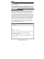
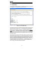
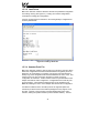
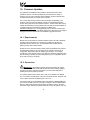
13.1.3 Application Configuration
As previously mentioned, any PC communication software and PC serial port
can be used. The software configuration example given here will be for
Windows HyperTerminal communicating via COM1.
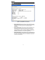
Figure 10 shows the “Connect To” tab of the properties window for COM1.
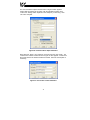
Figure 11 shows the window that appears when “Configure” is selected in the
“Connect To” tab. Figure 12 shows the “Settings” tab of the properties window.
Most of these settings are their default values: usually the only change needed
is the “Bits per second” setting shown in Figure 11.
30
Figure 10: HyperTerminal Properties…Connect To
Figure 11: HyperTerminal Properties…Connect To…Configure
31
Figure 12: HyperTerminal Properties…Settings
32
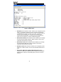
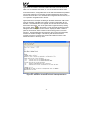
13.2 Invocation
The console provides standard access and editing methods for the various
configuration items (ports, points and their associated attributes). It is important
to note that whenever you modify the point database and are ready to restart
the gateway (“exit”), you must save the database to the internal file system prior
to restarting or your changes will be lost. The console will automatically ask
you if you would like to save the database to the file system every time you exit
even if you did not modify it. If the database was unchanged, then saving is not
required. Before modifying the configuration, it is a recommended practice to
download a configuration file to your PC for backup purposes, so that the
original configuration can be restored if any unintended changes are made.
To enter the console, simply type “menu” and press the Enter key. You will
then be notified that all communication tasks will be terminated for the duration
of the editing (refer to Figure 13). It is important to ensure that all connected
devices are in a safe state such that loss of communications will not pose a
danger to equipment or personnel. Exiting the console will reset the gateway
and restart network communications using the current configuration data.
At most console prompt locations, typing “x” will return you to the previous
menu, and typing “menu” will return you to the main menu. Also note that
console commands are not case-sensitive.
Figure 13: Console Invocation
33
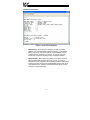
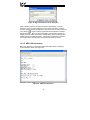
13.3 Main Menu
The main menu is shown in Figure 14. All gateway configuration is performed
by “drilling down” into progressively lower-level menus.
Figure 14: Console Main Menu
All navigation and data entry commands are input by simply entering the menu
selection number to the right of the “>” symbol along with any required data
fields at the console prompt. In Figure 14, for example, entering the menu
selection number “1” (without the quotation marks) will bring up the View/Edit
Points submenu. Throughout this manual, example console entry strings will
be provided enclosed in quotation marks to delineate them from the description
text: whenever actually entering the console strings, however, do not include
the quotation marks.
When additional data fields are required with a data entry command, they will
be indicated by square brackets (“[…]”) after the menu selection number. All
data entry commands and data fields must be separated by spaces. Because
data entry commands and data fields are delineated by spaces, spaces are
therefore not allowed within data fields (such as name strings). In these cases,
it is usually convenient to use an underscore “_” in place of a space. For
example, attempting to enter a point’s name as “My point” would result in an
error, but “My_point” would be perfectly acceptable.
34
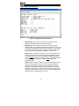
13.3.1 View/Edit Points
Main menu selection number 1 displays a screen which shows a summary of
the current point configuration (see Figure 15). This screen only displays the
point number and the point name: in order to access more detailed point
information, menu selection number 1 “Edit/View a Point” must be entered with
the additional argument of the targeted point’s number. The syntax used to
edit/view point #1 is shown at the bottom of Figure 15.
Only 10 points are shown at a time (of 100 total available in the unit). Menu
selection 2 “More Points” allows the next 10 points to be viewed.
Figure 15: View/Edit Points
Entering “1” with a point’s number (such as “1 1”, as shown at the bottom of
Figure 15) at the Edit Points submenu will display and allow editing of that
point’s mapping and definition information. Refer to Figure 16 for an example.
When editing a point, the top half of the screen (menu selections 1-4) contains
point attributes that are protocol-independent. The bottom half of the screen
(menu selections 5-9) contains the menu options for editing point attributes that
are protocol-specific.
35
Figure 16: Edit a Point
•
Edit Name: Menu selection number 1 allows you to change the point’s
name. For example, the bottom of Figure 16 shows an example of
changing point #1’s name to output_voltage. The point’s name is
purely for user recognition of a point, and has no bearing upon
communications functionality. To clear the point’s name field, just
enter the menu selection (“1”) with no additional argument.
•
Edit Timeout Enable: Menu selection number 2 allows you to change
the point’s timeout enable selection. Refer to section 12.2 for more
information about timeout processing.
•
Edit Timeout value: Menu selection number 3 allows you to change
the point’s timeout data value. Refer to section 12.2 for more
information about timeout processing.
•
Edit Source Port: Menu selection 4 allows you to change the point’s
source port. Refer to section 12.3 for more information about source
ports.
•
Edit Toshiba, Mitsubishi, Modbus Master/Slave/Plus: Menu
selections 5-9 allow you to edit/view protocol-specific point attributes.
Enter the menu selection corresponding to the protocol you wish to
edit/view.
36
Toshiba Point Attributes
Figure 17: Edit Toshiba Attributes
•
Edit Address: Menu selection 1 allows you to edit the network
address of the Toshiba ASD that this point refers to. This address
field is only used in conjunction with the Toshiba RS485 protocol:
Toshiba common-serial port connections are point-to-point, and
therefore do not require targeting a drive at a specific address.
•
Edit Parameter: Menu selection 2 allows you to edit the Toshiba
ASD parameter that this point will access. Figure 17 shows an
example of how to change the current setting of FA00 to FA04 (which
would be a typical change if the Toshiba RS485 protocol were to be
used with this point). Note that Toshiba parameter values must be
entered in hexadecimal format.
37
Mitsubishi Point Attributes
Figure 18: Edit Mitsubishi Attributes
•
Edit Address: Menu selection 1 allows you to edit the network
address of the Mitsubishi ASD that this point refers to.
•
Edit Parameter: Menu selection 2 allows you to edit the Mitsubishi
ASD parameter that this point will access. Figure 18 shows an
example of how to change the current setting of 1 to 1014.
38
Modbus Master Point Attributes
Figure 19: Edit Modbus Master Attributes
•
Edit Address: Menu selection 1 allows you to edit the network
address of the Modbus slave that this point refers to.
•
Edit Register: Menu selection 2 allows you to edit the Modbus
holding register or input register that this point will access. The type of
register accessed (holding or input) will be determined on the basis of
the “Read FC” setting (see below). Figure 19 shows an example of
how to change the current setting of register 1 to register 50.
•
Read FC: Menu selection 3 allows you to choose the Modbus “read”
function code that will be used to read from the designated register.
The default setting of function code 03 (read holding registers) will
access a holding register on the remote device. By selecting function
code 04 (read input registers), a Modbus input register will be
accessed instead.
•
Write FC: Menu selection 4 allows you to choose the Modbus “write”
function code that will be used to write to the designated holding
register (this setting does not apply to input registers, as they are
read-only). The default setting is function code 16 (preset multiple
registers). Alternatively, this setting can be changed to function code
06 (preset single register) in order to connect to those Modbus slave
devices that do not support function code 16.
39
Modbus Slave Point Attributes
Figure 20: Edit Modbus Slave Attributes
•
Edit Register: Menu selection 1 allows you to assign a Modbus
register (accessible as either a holding register or input register) to this
point. Figure 20 shows an example of how to change the current
setting of 7 to 8. Note that this Modbus register index is used whether
accessing the point via Modbus RTU or Modbus Plus MSTR
commands.
40
Modbus Plus Point Attributes
Figure 21: Edit Modbus Plus Attributes
•
Edit Get Global Node: Menu selection 1 allows modification of the
selected node on the network from which this point will consume (get)
global data. This value is ignored if the “Get Global Offset” is
“DISABLED”.
•
Edit Get Global Offset: Menu selection 2 allows modification of the
offset within the Get Global Node’s data block that this point will
consume (get) from. Figure 21 shows an example of changing this
point’s “get” offset from 0 to 10 in node #1’s data block. When set to
“DISABLED”, this point will not consume any global data.
•
Edit Put Global Offset: Menu selection 3 allows modification of the
offset within the gateway’s global data block that will be populated with
this point’s “value” attribute. When set to “DISABLED”, this point will
not produce any global data.
41
Implementing Global Data
As indicated above, three global data configuration items exist for each point in
the point database: a “get” node, a “get” offset, and a “put” offset. If a given
point is intended to be accessed only via standard MSTR write and read
commands (MSTR functions 1 and 2, respectively), then both the “get” and
“put” offsets should be set to “DISABLED”. Standard MSTR read and write
commands can then be used to access the point by targeting its “Modbus Slave
Register” assignment.
If global data is to be used, however, then one of the global data selections
must be enabled by programming it with an offset value (in the case of a “put”),
or with a node address and an offset value (in the case of a “get”). If the point
is to be written to by another device on the Modbus Plus network, then the
MBP-100 must be configured to “get” data from that selected device’s global
data block. If the point’s value is to be broadcast to the network, however, then
the MBP-100 will “put” the point’s value into its own global data block, where
other network nodes can “get” the data if desired. It is even possible to
configure a specific point to both “get” and “put” global data (in effect
performing global data “relaying”).
Because the gateway can be configured to retrieve global data from any offset
(offset values 0-31) from any node (address values 1-64), very powerful peerto-peer networking configurations can be created that entirely bypass the need
for a PLC “master” executing MSTR instructions. The only configuration
constraint with respect to global data is that “put” offsets must be unique. For
example, if point #9 has been assigned a “put” offset of 5 (meaning that this
point’s value will be placed in the 6th word from the start of the gateway’s global
data), and if point #13 is also assigned a “put” offset of 5, then only the value of
the point with the larger numerical index (in this case, point #13) would appear
at the duplicated offset. “Get” global data configuration has no such limitation:
it is perfectly acceptable for multiple points to consume data from the same
offset in a common node’s global data block. This type of configuration may be
particularly useful in synchronized systems, for example, where multiple points
(and their associated devices on other networks) follow a “leader” value being
broadcast by a single Modbus Plus node.
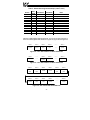
As a brief example of a global data implementation, Table 2 shows how 12
points in the point database might be configured for a specific application. Note
that some points are consuming global data, some points are producing global
data, and some points do not access global data at all (either they are not being
used for Modbus Plus access, or they are accessed only via “standard” MSTR
read or write commands).
42
Table 2: Global Data Assignment Example (x=Don’t Care)
Get
Node
3
x
8
8
3
x
x
x
x
x
x
x
Point #
1
2
3
4
5
6
7
8
9
10
11
12
Get Offset
Put Offset
Note
2
DISABLED
5
5
3
DISABLED
DISABLED
DISABLED
DISABLED
DISABLED
DISABLED
DISABLED
DISABLED
DISABLED
DISABLED
DISABLED
DISABLED
0
1
4
DISABLED
5
7
8
Get from node #3
No global data access
Get from node #8
Get from node #8
Get from node #3
Put
Put
Put
No global data access
Put
Put
Put
With the indicated global data assignments, we can get a logical overview of
the three relevant global data areas from Figure 22, Figure 23 and Figure 24.
Offset 0
ignored
Offset 1
Offset 2
Offset 3
………
Offset 31
ignored
Point #1
value
Point #5
value
………
ignored
Figure 22: "Get" Global Data From Node Address #3
Offset 0
ignored
………
Offset 5
Offset 6
………
Offset 31
………
Point #3 and
#4 value
ignored
………
ignored
Figure 23: "Get" Global Data From Node Address #8
Offset 0
Offset 1
Offset 2
Offset 3
Offset 4
Offset 5
Point #6
value
Point #7
value
unused
unused
Point #8
value
Point #10
value
Offset 6
Offset 7
Offset 8
Offset 9
………
Offset 31
unused
Point #11
value
Point #12
value
unused
………
unused
Figure 24: "Put" Global Data From MBP-100
43
13.3.2 View/Edit Ports
Main menu selection number 2 displays a screen which shows a summary of
the current port configuration (see Figure 25). This screen only displays the
current protocol selected for each port: in order to access more detailed port
information, select the menu number corresponding to the desired port. Menu
selections 1-3 correspond to the Toshiba common serial ASD ports, and these
contain no other port configuration other than enable/disable. The syntax used
to disable port ASD1 is shown at the bottom of Figure 25.
Figure 25: View/Edit Ports
44
RS485/232 Port Configuration
Figure 26: Edit Port Configuration
•
Edit Protocol Selection: Menu selection 1 allows you to change
what serial protocol is running on the selected port. Note that not all
ports run the same protocols. Figure 26 shows an example of
changing the protocol selection on the RS485 port from Disabled to
Modbus Slave.
•
Edit Baudrate: Menu selection 2 allows you to change the baudrate
for the selected port. Note that the baudrate for some protocols is
determined by the specification, and these will therefore ignore this
setting.
•
Edit Parity: Menu selection 3 allows you to change the parity for the
selected port. Note that the parity for some protocols is determined by
the specification, and these will therefore ignore this setting.
•
Edit address: Menu selection 4 allows you to edit the network
address that the selected port will respond to. This setting is
applicable for slave protocols only.
•
Edit Timeout: Menu selection 5 allows you to edit the timeout time
for the selected port. Refer to section 12.2 for more information on
timeout processing.
45
13.3.3 Load Points
Main menu selection number 3 allows the retrieval of a predefined configuration
into working memory (see Figure 27). Loading one of these configurations
overwrites the existing point configuration.
Currently, entering submenu selection 1 returns the gateway’s configuration to
its factory default state.
Figure 27: Loading a Point File
13.3.4 Xmodem Point File
Main menu selection number 4 gives access to the “xmodem” command, which
allows unit configuration files to be transferred between the gateway and a PC.
Whenever unit configuration is completed, it is strongly recommended that a
backup copy of the configuration file be downloaded from the unit to a PC. One
reason for this is in case it becomes necessary to restore a previous
configuration at a later time. Another reason is that it may be desirable to load
multiple units with the same configuration. Configuration files contain all point
and port settings. A downloaded configuration file can be uploaded to any
MBP-100, allowing the user to clone multiple units with the same configuration.
Two different variations of the Xmodem protocol are supported (CRC and
Checksum) for those serial communication packages that only support one or
the other. However, some programs can automatically adapt to the user’s
selection, making the specific Xmodem protocol selection arbitrary. The first
46
argument of the xmodem command indicates the mode, and must be set to
either “/crc” for Xmodem CRC mode, or “/cs” for Xmodem checksum mode.
As mentioned above, configuration files can be both downloaded and uploaded.
The second argument in the xmodem command indicates the action to take,
and must be set to either “/d” to download the configuration file from the unit, or
“/u” to upload a configuration file to the unit.
Figure 28 shows an example of initiating an Xmodem download in CRC mode.
Once the message “The MBP-100 is ready to send its configuration file via
Xmodem…Download the file now” appears, the user has 30 seconds to start
the Xmodem download. This can be performed in HyperTerminal by clicking
the “receive” button ( ) on the tool bar. Figure 29 shows the dialog box that
will appear after clicking the “receive” button. Specify the folder in which to
place the received file, select Xmodem as the receiving protocol, and click
“Receive”. One last dialog box will prompt the user to name the received file,
and then the transfer will begin. This will only take several seconds to
complete, and at the conclusion the console will indicate the status of the
transfer and return to the entry menu.
Figure 28: “Xmodem” Command Overview and Implementation
47
Figure 29: HyperTerminal receive file dialog box
When uploading a file, the procedure is similar to downloading. Enter “/u”
instead of “/d” for the action parameter of the xmodem command. Once the
xmodem upload command is entered, the user will have 30 seconds to click the
“send” button ( ) on the tool bar in HyperTerminal and initiate the Xmodem
upload transaction. Upon successful completion of the Xmodem upload, the
integrity of the file will be checked and, if valid, will be copied to both the unit’s
working memory and flash file system. The previous configuration cannot be
recovered (unless a corresponding configuration file exists, of course).
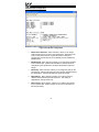
13.3.5 MBP-100 Information
Main menu selection 5 provides some basic information about the gateway,
such as firmware version (see Figure 30).
Figure 30: MBP-100 Information
48
14. Protocol-Specific Information
This section will discuss topics that are specific to each of the available network
selections.
14.1 Modbus
The gateway supports Modbus slave and master functionality via Modbus RTU.
The slave implementations share common access methods, which is to say
they support the same functions and reference the internal points via a
common “Modbus Slave” register assignment. Other notes of interest are:
•
Points are addressed by their assigned holding register (4X reference) or
input register (3X reference) via Modbus slave protocols.
•
Points can access both holding registers (4X references) and input
registers (3X references) via Modbus master protocols.
•
Supported Modbus slave functions are indicated in Table 3.
Table 3: Supported Modbus Slave Functions
Function Code
1
2
3
4
5
6
8
15
16
Function
Read coils
Read input status
Read multiple registers
Read input registers
Write coil
Write single register
Diagnostics (subfunction 0 only)
Force multiple coils
Write multiple registers
•
Register number entry radix is decimal (e.g. 10 = 1010)
•
Configuration tip: Improved network utilization may be obtained by
appropriately grouping points into blocks having contiguous register
assignments. In this way, the “read multiple registers”, “read input
registers” and “write multiple registers” functions can be used to perform
transfers of larger blocks of registers using fewer Modbus transactions
compared to a situation where the read/write registers were arranged in an
alternating or scattered fashion.
49
•
Because the transaction is handled locally within the gateway, write data
checking is not available. For example, if a write is performed to a register
with a data value that is out-of-range of the corresponding “source port”
object, no Modbus exception will be immediately returned. However, the
point will always reflect the “source port” status and object value. In other
words, if such an out-of-range write attempt is performed, the unsuccessful
“source port” network write can be observed by reading the current
(unchanged) value of the point during a subsequent Modbus transaction.
14.1.1 Coil & Discrete Input Mappings
The Modbus slave implementation provides read/write support for coils (0X
references) and read-only support for discrete inputs (1X references). These
will collectively be referred to from here on out as simply “discretes”. Accessing
discretes does not reference any new physical data: discretes are simply
indexes into various bits of Modbus registers. What this means is that when a
discrete is accessed, it is resolved by the gateway into a specific register, and a
specific bit within that register. The pattern of discrete-to-register/bit
relationships can be described as follows:
Discrete 1...16 map to register #1, bit0...bit15 (bit0=LSB, bit15=MSB)
Discrete 17...32 map to register #2, bit0...bit15, and so on.
Arithmetically, the discrete-to-register/bit relationship can be described as
follows: For any given discrete, the register in which that discrete resides can
be determined by:
⎢ discrete + 15 ⎥
register = ⎢
⎥⎦
16
⎣
…Equation 1
Where the bracket symbols “⎣ ⎦” indicate the “floor” function, which means that
any fractional result (or “remainder”) is to be discarded, with only the integer
value being retained.
Also, for any given discrete, the targeted bit in the register in which that discrete
resides can be determined by:
bit = (discrete − 1) % 16
…Equation 2
Where “discrete” ∈[1…65535], “bit” ∈[0…15], and “%” is the modulus operator,
which means that any fractional result (or “remainder”) is to be retained, with
the integer value being discarded (i.e. it is the opposite of the “floor” function).
From these equations, it can be seen that the largest register number that can
be accessed via this discrete-to-register mapping method is 4096 (which
contains discrete #65535).
50
For clarity, let’s use Equation 1 and Equation 2 in a calculation example. Say,
for instance, that we are going to read coil #34. Using Equation 1, we can
determine that coil #34 resides in register #3, as ⎣3.0625⎦ = ⎣3 r1⎦ = 3. Then,
using Equation 2, we can determine that the bit within register #3 that coil #34
targets is (34-1)%16 = 1, as 33%16 = mod(2 r1) = 1. Therefore, reading coil
#34 will return the value of register #3, bit #1.
Note that this discrete-to-register/bit relationship holds true regardless of
whether or not register #3 is assigned to a point. If register #3 is not assigned
to a point, then a Modbus exception will be returned. Either way, coil #34 will
always access register #3, bit #1.
14.1.2 Modbus RTU Slave
•
Broadcast (for functions 5, 6, 15 and 16) is supported.
•
Network characteristics selections
o Baud rate: 2400 / 4800 / 9600 / 19200 / 38400 bps
o Parity: odd / even / none (1 stop bit) / none (2 stop bits)
14.1.3 Modbus RTU Master
•
Supported Modbus master functions are indicated in Table 4. These
functions are automatically invoked by the gateway in response to point
read or write requests. The specific read or write function code used
depends on the point’s assigned configuration.
Table 4: Supported Modbus Master Functions
Function Code
3
4
6
16
Function
Read multiple registers
Read input registers
Write single register
Write multiple registers
•
The slave response timeout (in seconds) is assigned via the designated
port’s “Timeout” selection. If “0” is chosen (an invalid timeout time), the
gateway will use a 2s timeout by default.
•
Network characteristics selections
o Baud rate: 2400 / 4800 / 9600 / 19200 / 38400 bps
o Parity: odd / even / none (1 stop bit) / none (2 stop bits)
51
•
Note that various manufacturers will document their Modbus slave
products in different ways. In particular, according to the Modbus
specification, registers have two different indices at which they can be
referenced: their “known as” value (which starts at number 1) and their
“addressed as” value (which is always 1 less than the “known as” value).
The “known as” value is typically the number that is presented for human
entry or consumption, while the “addressed as” value is the number that
appears “on the wire” when the Modbus packet is sent from master to
slave. This gateway follows this generally-accepted industry paradigm,
where a point’s configured Modbus master “register” value is decremented
by 1 before it is placed “on the wire”. Some vendors, however, will
document their slave device’s “addressed as” values in their literature,
which means that these register indices must have 1 added to them when
entered into the gateway’s “Modbus master register” field.
For example, the Toshiba VF-AS1/G9 drive’s Modbus RTU slave protocol
implementation & corresponding user’s manual references all internal ASD
parameters using “addressed as” values. This means that (in addition to
the required conversion from Toshiba’s native hexadecimal radix to the
Modbus protocol’s natural decimal radix) these parameter values must
have 1 added to them when they are to be accessed via an ICC gateway
executing the Modbus RTU master protocol.
e.g. VF-AS1/G9 “command 1” parameter is documented to be FA00 in the
Toshiba literature. Converting this to decimal, we arrive at a value of
64000. To allow a point in the gateway’s database to correctly access the
“command 1” parameter via Modbus RTU, therefore, that point’s Modbus
master “register” attribute must be set to 64001 (which will result in an
address value of 64000 (0xFA00) “on the wire”).
52
14.2 Modbus Plus
•
Supported MSTR functions are indicated in Table 5.
Table 5: Supported MSTR Functions
Function Code
Function
1
2
5
6
Write Registers
Read Registers
Write Global Data
Read Global Data
•
Modbus Plus register assignments are common between the Modbus Plus
and Modbus RTU Slave protocols. In other words, when a point in the
point database has been assigned a “Modbus Slave” register index, both
Modbus Plus and Modbus RTU Slave protocols will access that point’s
value by referencing the same register index.
•
Configuration tip: Improved network utilization may be obtained by
appropriately grouping points into blocks having contiguous “Modbus
Slave” register assignments. In this way, the “read registers” and “write
registers” functions can be used to perform transfers of larger blocks of
registers using fewer Modbus Plus transactions compared to a situation
where the read/write registers were arranged in an alternating or scattered
fashion.
•
Because the transaction is handled locally within the gateway, write data
checking is not available. For example, if a write is performed to a register
with a data value that is out-of-range of the corresponding “source port”
object, no Modbus Plus exception will be immediately returned. However,
the point will always reflect the “source port” status and object value. In
other words, if such an out-of-range write attempt is performed, the
unsuccessful “source port” network write can be observed by reading the
current (unchanged) value of the point during a subsequent Modbus Plus
transaction.
53
14.3 Toshiba Common Serial ASD Protocol
•
The gateway can act as a Toshiba ASD master via its dedicated common
serial (TTL) port connections. All Toshiba drives that include a common
serial port are supported.
•
No configuration is necessary, as the gateway automatically adapts to the
ASD’s configured characteristics.
•
The RS485 port and the ASD1 port of the gateway are internally shared,
which means that they both cannot be active simultaneously. Also, the
RS485 port’s configuration has priority over that of the ASD1 port: if any
protocol is assigned to the RS485 port, then the ASD1 port will be
automatically disabled. Note, however, that the ASD2 and ASD3 ports will
at all times operate independently of all other network ports.
•
All parameter writes use the drive’s RAM / EEPROM data write (“W”)
command. For all writes that target the drive’s EEPROM, be sure to follow
Toshiba’s guidelines regarding the number of times a specific parameter
can be written without risk of EEPROM damage.
•
Point parameter number entry radix is hexadecimal (e.g. 10 = 0x0010 or
1610)
14.4 Toshiba RS485 ASD Protocol
•
The gateway can act as a Toshiba ASD master via its RS485 port. All
Toshiba drives that implement the Toshiba protocol and provide either a
built-in or option-based RS485 port are supported.
•
Because the gateway implements a 2-wire (half-duplex) RS485 network,
the drive(s) involved must also be connected via 2-wire mode. Optionally,
it is also possible to convert the gateway’s network from 2-wire (halfduplex) to 4-wire (half-duplex) via an external repeater such as the
485OPIN from B&B Electronics (http://www.bb-elec.com).
•
Note that Toshiba 7-series drives configured for 2-wire mode (F821=0)
shipped prior to early 2006 may exhibit an issue that can cause their
RS485 ports to stop communicating after a certain amount of time. Please
contact Toshiba technical support to confirm your configuration prior to
using 2-wire RS485 mode on these drives.
•
The required drive configuration will vary depending on the specific drive(s)
involved. In general, most parameters are freely configurable to match the
gateway’s port settings (baud rate, parity etc.) The most critical selection,
however, is that if the drive is directly connected to the gateway via 2-wire
mode, then the drive must be properly configured for 2-wire RS485. Note
54
that this may involve hardware configuration in addition to parameter
changes. For example, G7/Q7/H7-series drives have duplex selection
jumpers located on the drive’s control board near the communication ports.
For these drives, both jumpers must be placed in the “HALF” position.
Refer to Figure 31 for an example detailed view of correctly-positioned
duplex selection jumpers.
Figure 31: RS485 Terminal Block (CN3) and Duplex Selection Jumpers
•
The Toshiba RS485 terminal block connections for G7/Q7/H7/W7 drives
are shown in Figure 32 for reference only. Because there are many
possible RS485 port configurations & options available for the various
Toshiba drives, please refer to the relevant Toshiba documentation for
your drive.
A
B
Signal Ground
Shield
Figure 32: G7/Q7/H7 RS485 Terminal Block (CN3) Connections
55
•
The RS485 port and the ASD1 port of the gateway are internally shared,
which means that they both cannot be active simultaneously. Also, the
RS485 port’s configuration has priority over that of the ASD1 port: if any
protocol is assigned to the RS485 port, then the ASD1 port will be
automatically disabled. Note, however, that the ASD2 and ASD3 ports will
at all times operate independently of all other network ports.
•
All parameter writes use the drive’s RAM / EEPROM data write (“W”)
command. For all writes that target the drive’s EEPROM, be sure to follow
Toshiba’s guidelines regarding the number of times a specific parameter
can be written without risk of EEPROM damage.
•
The drive response timeout (in seconds) is assigned via the designated
port’s “Timeout” selection. If “0” is chosen (an invalid timeout time), the
gateway will use a 1s timeout by default.
•
Network characteristics selections
o Baud rate: 2400 / 4800 / 9600 / 19200 / 38400 bps
o Parity: odd / even / none (1 stop bit) / none (2 stop bits)
•
Point parameter number entry radix is hexadecimal (e.g. 10 = 0x0010 or
1610)
56
14.5 Mitsubishi ASD Protocol
•
The gateway acts as a Mitsubishi protocol master via its RS485 port.
Adjustable speed drives such as the FR-A500/E500/F500 series and F700series that support the Mitsubishi protocol can be accessed. Also
supported are MGI Technologies, Inc. M3000, M4000 and M5000-series
drives that support the Mitsubishi protocol.
•
For 500-series drives, the gateway can connect to the ASD via either the
PU (panel) connector, or via an optional FR-A5NR computer link board.
Because the ASDs externally present a 4-wire RS485 network, connecting
them to the gateway requires jumpering the network wires for 2-wire format
(i.e. connecting SDA-RDA and SDB-RDB).
When Using an FR-A5NR Card
Connect as shown in Figure 33.
A
(TB:1)
B
(TB:2)
Signal
Ground
(TB:3)
Figure 33: FR-A5NR Connections
When Using the PU Port
Connecting to the drive’s RJ-45 PU port will likely require building a custom
cable. For simplicity, a standard 8-conductor Ethernet patch cable can be
used as a starting point. There are two standard color schemes for the
wire pairs in such cables as defined by the Electronic Industry Association /
Telecommunications Industry Association (EIA-TIA). These two standards
are called T-568B and T-568A (refer to Figure 34). The most common
color scheme is T-568B, and will therefore be the one used for this
example connection. If starting with a cable wired according to the T-568A
specification, just interchange the colors to achieve the same pin
connections.
57
Connect as shown in Figure 35.
Figure 34: EIA/TIA Wiring Standards
RDA SDA
SDB RDB
A
(TB:1)
B
(TB:2)
Signal
Ground
(TB:3)
Figure 35: PU Port Connections
•
For 700-series drives, the gateway can connect to the ASD via either the
PU (panel) connector as indicated in Figure 35, or via the on-board RS485
terminals. Because both of these ports externally present a 4-wire RS485
network, connecting them to the gateway requires jumpering the network
wires for 2-wire format (i.e. connecting SDA-RDA and SDB-RDB). When
using the on-board RS485 terminals, connect as shown in Figure 36.
58
A
(TB:1)
B
(TB:2)
Signal
Ground
(TB:3)
Figure 36: 700-Series ASD Connections
•
Note that although the 700-series ASD also supports the Modbus RTU
protocol, the initial ASD firmware did not support the Modbus RTU protocol
in 2-wire format. Therefore, using the Mitsubishi protocol may be the only
available method to communicate with the gateway (ASD parameter 549
must be “0”). Contact Mitsubishi Technical Support for more information.
•
The slave response timeout is determined via the gateway’s RS485 port
timeout value setting. If the timeout value is set to 0, a default timeout time
of 2s is used.
•
ASD communication characteristics are dictated by parameters 117-124
(PU port) and 331-341 (RS485 port). Most of these parameters can be set
as desired by the user. However, the following parameters must be set as
indicated to successfully connect to the gateway:
Parameter 119/333 (stop bits/data bits)......... Must be set for 8 data bits
Parameter 123/337 (wait time setting) ........... Must be set to 9999
Parameter 124/341 (CR/LF selection) ........... Must be set to 1 (CR only)
•
ASD parameter number entry radix is decimal (e.g. 10 = 1010)
•
Any numerically-addressed parameter defined by the Mitsubishi protocol
reference manual is directly accessible (base frequency = parameter #3,
etc.). However, some ASD data objects do not have parameter numbers
assigned by Mitsubishi. For these data objects, the additional parameter
numbers indicated in Table 6 have been assigned. For further information
59
on these parameters, please refer to the relevant Mitsubishi
documentation.
Table 6: Additional Mitsubishi Parameter Assignments
Parameter
Number
1000
1001
1002
1003
1004
1005
1006
1007
1008
1009
1010
1011
1014
1015
1016
1017
Item
Second parameter switch-over
Frequency command (RAM)
Frequency command (EEPROM)
Frequency monitor
Output current monitor
Output voltage monitor
Special monitor
Special monitor selection number
Most recent #1 and #2 alarms / alarm clear
Most recent #3 and #4 alarms
Most recent #5 and #6 alarms
Most recent #7 and #8 alarms
Inverter status monitor / operation command
Operation mode acquisition
All parameter clear
Inverter reset
60
14.6 Teco-Westinghouse ASDs
The gateway can act as a Modbus RTU protocol master via its RS232 and RS485 ports, which allows connection to Modbus-capable Teco-Westinghouse
ASDs. While it is possible to connect to any Teco-Westinghouse ASD that
supports Modbus (either RS232 or RS485), this section will discuss in particular
some important considerations to make note of when connecting to, and
interacting with, the PA7300 (with installed PA-M card) and MA7200 ASDs via
RS485.
14.6.1 MA7200
•
Connect the gateway’s RS485 port "A" terminal to the drive’s “S+” terminal,
the gateway’s RS485 port "B" terminal to the drive’s “S-“ terminal, and the
gateway’s RS485 port "SG" terminal to the drive’s “GND” terminal.
•
Although the latest MA7200 Modbus manual (dated 2001/06/05) indicates
that the maximum baud rate (set via parameter Sn-37) is 9600 baud, all
newer drives actually support 19.2kbaud (Sn-37 = 4).
•
When drive parameter Sn-38 (parity) is set to 0 (no parity), the gateway’s
port configuration can be set to either “none / 1 stop bit” or “none / 2 stop
bits” (either setting will work).
•
Note that the default value of drive parameter Cn-27 (time-out check) is
1.0s. Because the minimum timeout time that the gateway’s port can be
configured for is 1s, to avoid nuisance timeout faults on the drive it is
recommended to either set parameter Cn-27 to 0.0s (if timeout checking is
not needed), or to a value of 2.0s or more (if timeout checking is desired).
•
If run/stop etc. commands are to come from network, set drive parameter
Sn-04 to 2.
•
If frequency reference is to come from network, set drive parameter Sn-05
to 2.
•
Note that the holding register “address” column provided in the MA7200
Modbus manual contains the Modbus “addressed as” (on-the-wire) values,
which are always 1 less than the Modbus “known as” values (which the
gateway’s configuration requires). Additionally, this “address” column
indicates the holding register numbers in hexadecimal, which is atypical for
Modbus decimal-based register assignments. Therefore, to calculate the
“register” assignment that must be programmed into the gateway, first
convert the documented “address” to a decimal value, and then add 1. For
example, the MA7200’s “output frequency” register is documented to exist
at register 0025H. Converting this number to decimal and adding 1
therefore results in a “known as” register value of 38, which can then be
entered in the Modbus master “register” assignment of a point on the
gateway.
•
The MA7200 drops Modbus packets frequently when it is in PRG mode.
61
•
The MA7200 Modbus manual indicates that control data registers
(0000H..000FH) are read/write, but reading always returns 0.
•
All drive parameters may be read at any time, but only Cn parameters can
be written while the inverter is in DRV mode. The inverter must be in PRG
mode to write any other parameters.
•
The drive parameters that configure the RS-485 communication
characteristics (baud rate, etc.) do not take effect until the drive is reset.
•
Cn parameter changes take effect instantly, while others don't take effect
until the inverter is put back into DRV mode or the parameters are saved
into EEPROM and the inverter is reset.
•
The “write to EEPROM” register (0900H) is write-only. Therefore, if this
drive register is mapped to a point in the gateway, this gateway point will
always be flagged as “in error”, as the gateway will always attempt to read
this register as long as a new value is not being written to it. The impact of
this point always being “in error” (if any), is dependant on the protocol used
to access this point.
14.6.2 PA7300
•
Set JP1 on the PA-M card to the "RS-485" position.
•
Set both SW1-1 and SW1-2 on the PA-M card to the "OFF" position.
•
Connect the gateway’s RS485 port "A" terminal to the PA-M card’s TB1 "1"
terminal, the gateway’s RS485 port "B" terminal to the PA-M card’s TB1 "2"
terminal, and the gateway’s RS485 port "SG" terminal to the PA-M card’s
TB1 "E" terminal.
•
Note that the default value of drive parameter Cn-31 (time-out check) is
1.0s. Because the minimum timeout time that the gateway’s port can be
configured for is 1s, to avoid nuisance timeout faults on the drive it is
recommended to either set parameter Cn-31 to 0.0s (if timeout checking is
not needed), or to a value of 2.0s or more (if timeout checking is desired).
•
If run/stop etc. commands are to come from network, set Sn-08 to XX0X.
•
If frequency reference is to come from network, set Sn-08 to XXX0.
•
When drive parameter Sn-24 is set to XX00 (no parity), the gateway’s port
configuration must be set to “none / 2 stop bits”.
•
Note that the holding register “address / HEX” and “address / DEC”
columns provided in the PA7300 Modbus manual contain the Modbus
“addressed as” (on-the-wire) values, which are always 1 less than the
Modbus “known as” values (which the gateway’s configuration requires).
Therefore, to calculate the “register” assignment that must be programmed
into the gateway, add 1 to the documented “address / DEC” register
number. For example, the PA7300’s “output frequency” register is
documented to exist at decimal register 36. Adding 1 therefore results in a
62
“known as” register value of 37, which can then be entered in the Modbus
master “register” assignment of a point on the gateway.
63
15. Modicon PLC Programming Examples
This section of the manual is being provided solely as a brief overview of the
general ladder logic program architecture that can be used to interface with the
MBP-100 over a Modbus Plus network. For the most detailed information
available, the appropriate Modicon PLC Programming Manual should always be
consulted.
15.1 Ladder Logic and MSTR Instructions
Modicon PLCs that support Modbus Plus communications implement a special
instruction, called MSTR, which allows them to initiate Modbus Plus message
transactions via ladder logic. An example of a ladder logic program that
implements the MSTR instruction is shown in Figure 37.
MS TR on/off
MSTR Instruction
1
5
2
Instruction Activ e
3
Instruction End - Error
4
Instruction End - No Error
5
Instruction Completed
40050
(Control Block)
40100
(Data Area)
100
(# data registers)
3
4
Figure 37: Program Example for Modbus Plus Communications
64
15.1.1 MSTR Parameters
•
The number in the top portion of the MSTR block is the address of the first
of six registers in the Control Block, and is generally configured as
indicated in Table 7.
Table 7: MSTR Control Block Format
Address
Description
4x
Identifies which MSTR function is to be
executed. The MBP-100 supports
read, write, global read, and global
write.
4x + 1 Error code (Hex)
4x + 2 Number of consecutive registers to
read or write (n)
4x + 3 Starting register (s)
4x + 4 Destination node address
4x + 5 Master node address
Parameters
1 = Write Registers
2 = Read Registers
5 = Write Global Data
6 = Read Global Data
Read Only
1 <= n <= # data registers
1 <= s <= (65535-n)
2 – 64
1
There are small differences in the Control Block configuration depending
on the selected MSTR function and whether or not network elements such
as routers exist. Specific examples of each MSTR function can be found in
sections 15.3 through 15.6. These examples assume a single network
segment (no routers).
•
The number in the middle portion of the MSTR block is the address of the
first register in the Data Area. For write functions, the Data Area is the
location of the source (write) data. For read functions, the Data Area is the
destination of the returned read data.
•
The number in the bottom portion of the MSTR block is the Number of
Data Registers. This number defines the maximum number of registers in
the data area. Register “4x + 2” in the Control Block must be less than or
equal to this number. Also, each individual MSTR function has a maximum
value for this number, which is discussed in sections 15.3 through 15.6.
65
15.1.2 MSTR Inputs and Outputs
Figure 38 indicates the inputs and outputs associated with MSTR instructions.
INPUTS
Activ ate MSTR Instruction
OUTPUTS
MSTR Instruction
Instruction Activ e
40050
(Control Block)
Terminate MS TR Instruction
40100
Instruction End - Error
(Data Area)
100
(# data registers)
Instruction End - No Error
Figure 38: MSTR Inputs and Outputs
15.2 MSTR Function Error Codes
Table 8 indicates the error codes that may be output in the “4x+1” location of
the MSTR control block. These specific error codes can be generated by the
MBP-100. Additional error codes may be generated from other sources on the
Modbus Plus network.
Table 8: MSTR Error Codes
Error Code (Hex)
3001
3002
3003
Meaning
Slave device does not support the requested function
Nonexistent slave device registers requested
Invalid data value requested
15.3 MSTR Read Example
The following example demonstrates how to use the MSTR instruction to read 2
registers starting at register 1 from an MBP-100 located at Modbus Plus
network address 2.
1.
Set up a ladder logic program as shown in Figure 37. Set the top portion
of the MSTR Instruction to 40050. This will be the starting address of the
MSTR Control Block. Set the control block registers to the following values:
66
Address
40050
40051
40052
40053
40054
40055
2.
Description
MSTR function (read)
Error code
Number of consecutive registers to read
Starting register
Destination node address
Master node address
Register Value
2
Read Only
2
1
2
1
Set the middle portion of the MSTR instruction to 40100. This will be the
starting address of the MSTR Data Area. This is the location that will
contain the read data returned from the MSTR transaction.
Address
Value
40100 Value of register 1 @ network address 2
40101 Value of register 2 @ network address 2
3.
In this case, we are accessing two registers, so set the bottom portion of
the MSTR instruction (“number of registers”) to 2. In the case of MSTR
reads, this number cannot be greater than 125 by definition.
4.
Initiate the read command by closing internal relay 1. The data response
will be seen in the MSTR Data Area (register 40100).
15.4 MSTR Write Example
The following example demonstrates how to use the MSTR instruction to write
4 registers starting at register 1 to an MBP-100 located at Modbus Plus network
address 32.
1.
Set up a ladder logic program as shown in Figure 37.
2.
Set the top portion of the MSTR Instruction to 40060. This will be the
starting address of the MSTR Control Block. Set the Control Block
registers to the following values:
Address
40060
40061
40062
40063
40064
40065
3.
Description
MSTR function (write)
Error code
Number of consecutive registers to write
Starting register
Destination node address
Master node address
Register Value
1
Read Only
4
1
32
1
Set the middle portion of the MSTR instruction to 40200. This will be the
starting address of the MSTR Data Area. This is the location that will
contain the write data to be used in the MSTR write transaction.
67
Address
40200
40201
40202
40203
Value
Value to write to register 1 @ network address 32
Value to write to register 2 @ network address 32
Value to write to register 3 @ network address 32
Value to write to register 4 @ network address 32
4.
In this case, we are accessing four registers, so set the bottom portion of
the MSTR instruction (“number of registers”) to 4. In the case of MSTR
writes, this number cannot be greater than 100 by definition.
5.
Initiate the write command by closing internal relay 1. The data at registers
40200, 40201, 40202, and 40203 will be written to registers 1, 2, 3 and 4,
respectively, of the MBP-100 located at network address 32.
15.5 MSTR Global Read Example
The following example demonstrates how to use the MSTR instruction to read
32 words of global data from an MBP-100 located at Modbus Plus network
address 10.
1.
Set up a ladder logic program as shown in Figure 37.
2.
Set the top portion of the MSTR Instruction to 40070. This will be the
starting address of the MSTR Control Block. Set the control block registers
to the following values:
Address
40070
40071
40072
40073
40074
40075
3.
Description
MSTR function (global read)
Error code
Number of consecutive registers to read
Number of words available to read
Destination node address
Master node address
Register Value
6
Read Only
32
Read Only
10
1
Set the middle portion of the MSTR instruction to 40300. This will be the
starting address of the MSTR data area. This is the location that will
contain the data returned from the MSTR global data read transaction.
Address
40300
40301
:
40300+n
:
40331
Value
Value at offset 0 in global data from network address 10
Value at offset 1 in global data from network address 10
:
Value at offset n in global data from network address 10
:
Value at offset 31 in global data from network address 10
68
4.
In this case, we are accessing 32 words of global data, so set the bottom
portion of the MSTR instruction (“number of registers”) to 32. In the case
of MSTR global reads, this number cannot exceed 32 by definition.
5.
Initiate the global read command by closing internal relay 1. The data
response will be seen in the MSTR Data Area (starting at register 40300).
15.6 MSTR Global Write Example
The following example demonstrates how to use the MSTR instruction to write
32 words of global data from a Modbus Plus master located at network address
1. Once written, any node on the Modbus Plus network will have access to this
global data. The same global data values will continue to be available until
another global data write occurs. Global data can only be cleared by
performing a global data write with a length of 0 words.
1.
Set up a ladder logic program as shown in Figure 37.
2.
Set the top portion of the MSTR Instruction to 40080. This will be the
starting address of the MSTR Control Block. Set the control block registers
to the following values:
Address
Description
40080 MSTR function (global write)
40081 Error code
40082 Number of consecutive registers to write
3.
Register Value
5
Read Only
32
Set the middle portion of the MSTR instruction to 40400. This will be the
starting address of the MSTR Data Area. This is the location of the data
that will be written to the master’s network global data.
Address
40400
40401
:
40400+n
:
40431
Value
Value to write to offset 0 in the master’s global data
Value to write to offset 1 in the master’s global data
:
Value to write to offset n in the master’s global data
:
Value to write to offset 31 in the master’s global data
4.
In this case, we are writing 32 words of global data, so set the bottom
portion of the MSTR instruction (“number of registers”) to 32. In the case
of MSTR global writes, this number cannot exceed 32 by definition.
5.
Initiate the global write command by closing internal relay 1. The data at
registers 40400-40431 will be written to the master’s (station address 1)
global data.
69
16. Firmware Updates
The gateway’s embedded firmware resides in flash memory that can be
updated in the field. Firmware updates may be released for a variety of
reasons, such as custom firmware implementations, firmware improvements
and added functionality as a result of user requests.
ICC is continually striving to enhance the functionality and flexibility of our
products, and we therefore periodically release new embedded firmware to
achieve these goals and meet customer requests. Flash firmware files and all
related documentation (such as updated user manuals) can be downloaded as
complete board support packages (referred to as BSPs) from
http://www.iccdesigns.com. It is suggested that users check this Internet site
prior to installation, and then periodically afterwards to determine if new support
packages have been released and are available to upgrade their units.
16.1 Requirements
Besides the new firmware file, firmware updates require a PC with a Windows
operating system (Windows 95 or newer) and a serial port, the RFU PC
application (refer to section 16.3), and the RS232 cable included with the
gateway kit (ICC part number 10425).
Please be sure to read the firmware release notes and updated user’s manual
(included with the BSP) for any important notices, behavior precautions or
configuration requirements prior to updating your firmware. For example,
upgrading to a new firmware version may affect user-defined configuration files:
prior to starting an update procedure always back up your configuration file to a
PC for later recovery if necessary.
16.2 Connection
IMPORTANT: Note that the gateway will not be operating its system
control and communication tasks while its internal firmware is being updated.
Therefore, be sure to shut down the system to a known safe state prior to
initiating the firmware update procedure.
The gateway ships from the factory with a dust cover installed in the RS232
port. To minimize contamination of the port’s electrical contacts, keep this dust
cover in place whenever the RS232 port is not in use.
Connect the RJ45 end of the RS232 cable to the gateway’s RS232 (MMI) port,
and connect the DB9 end to the computer’s serial port. Move CONFIG switch
#8 to the “ON” (down) position: this will place the gateway into the “firmware
download” mode. Whenever CONFIG switch #8 is “ON”, the gateway can only
70
download firmware to its flash memory: all other application functions (such as
communications, console access etc.) will be disabled.
16.3 Using the RFU Utility
Support for downloading new application firmware to the gateway is provided by
the free Rabbit Field Utility (RFU), which is a 32-bit application that runs on
Microsoft Windows platforms. The RFU utility can be downloaded from ICC’s
website at http://www.iccdesigns.com. When downloading a new gateway
application BSP, always confirm that you also have the latest version of RFU,
as new .BIN firmware files contained in BSPs may require functionality found
only in the most recent RFU versions for successful downloading.
The remainder of this section will detail the RFU utility configuration and
firmware download procedures.
16.3.1 Required Files
When first downloaded, the RFU utility files are compressed into one selfextracting .EXE distribution file. Create a folder (such as c:\RFU), place the
distribution file in this folder, and then execute it. This will extract the
compressed files into that same folder. The distribution file is then unneeded
and can be deleted if desired. To run the RFU utility, double-click on the
RFU.EXE file icon.
16.3.2 First-Time Configuration
The first time the RFU utility is run on a computer, several configuration items
need to be confirmed. These configuration items are retained in the computer’s
registry from that point on, so reconfiguration is not required unless certain
parameters (such as which serial port to use on the computer) are changed.
The two configuration items that need to be confirmed are the communications
and bootstrap loaders path. First, select the “Setup…Communications” menu
item (refer to Figure 39).
Figure 39: RFU Main Screen
71
The Communications Options window shown in Figure 40 then appears.
Confirm that the settings are as shown, with the possible exception of the
“Comm Port” settings, which depends on the COM port you are using. Click
“OK” when complete.
Figure 40: Communications Options Window
Next, select the “Setup…File Locations” menu item from the main screen. The
“Choose File Locations” window shown in Figure 41 then appears. Confirm that
the correct paths to the referenced files are entered. Enter the correct paths if
necessary.
Figure 41: Choose File Locations Window
72
16.3.3 Transmitting Firmware Files
When a board support package (BSP) has been downloaded and unzipped, the
flash firmware file will be the one with “.BIN” as its file name extension.
Once the RFU utility has been configured, the flash firmware files can be
downloaded to the gateway by two different methods. The simplest way is to
drag the application firmware .BIN file’s icon and drop it onto the RFU utility’s
main screen. This will automatically initiate the download process.
Alternatively, select the “File…Load Flash Image” menu item (refer to Figure
42).
Figure 42: Load Flash Image Menu Selection
The flash image (.BIN file) selection window will then appear (refer to Figure
43). Browse to the location of the flash image file and select it. Clicking “OK”
will then initiate the download process.
Figure 43: Flash File Selection Window
While downloading, the RFU utility will indicate the download status. Once
complete, summary information will be displayed in the bottom status bar (see
Figure 44).
Figure 44: Summary Information
73
16.4 Wrap-Up
Once downloading is complete, close the RFU utility, move CONFIG switch #8
back to the “OFF” (up) position to exit “firmware download” mode, and cycle
power momentarily to the unit by either disconnecting the auxiliary power
supply and/or powering down all connected drives or momentarily removing all
drive communication cables from the unit.
When the unit powers up again, it will be running the new application firmware.
If the new firmware version release notes indicated that the configuration file
might need to be reloaded, then do so at this point.
When completed with RS232 port use, remove the RS232 cable and reinstall
the port dust cover to minimize contamination of the port’s electrical contacts.
74
NETWORK GATEWAY SERIES
ICC
INDUSTRIAL CONTROL COMMUNICATIONS, INC.
ICC
INDUSTRIAL CONTROL COMMUNICATIONS, INC.
Madison Office
1600 Aspen Commons, Suite 210
Middleton, WI USA 53562-4720
Tel: [608] 831-1255 Fax: [608] 831-2045
http://www.iccdesigns.com
MBP-100
Houston Office
12300 Dundee Court, Suite 212
Cypress, TX USA 77429-8364
MODBUS PLUS
MULTIPROTOCOL NETWORK GATEWAY
Printed in U.S.A
August 2008
ICC #10498-3.100-001