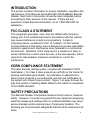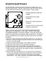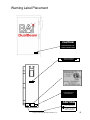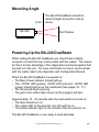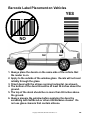
1
INSTALLATION AND MAINTENANCE
MANUAL FOR
BA-220 DualBeam BARCODE READER
revised 1/31/2009
Barcode Automation inc.
Doing It Better - Because We Care.
800-528-9167
407-327-2177
FAX 407-327-6172
Post Office Box 195268
Winter Springs, FL 32719-5268
email [email protected]
web page http://www.Barcode-Automation.com
FOREWORD
The purpose of this manual is to provide information on how to install,
configure, operate, and maintain the Barcode Automation BA-220
DualBeam Barcode Reading and Access Control System. Barcode
Automation Inc. has made every effort to insure that the information in
this manual is both accurate and adequate. It is recommended, in the
interest of safety and efficiency, that each section be read carefully
before installing or servicing this system.
This manual may not be copied or reproduced, in whole or in part,
without the express written consent of Barcode Automation inc.
Copyright 2009 Barcode Automation inc.
All rights reserved
January 2009
Copyright 1999-2009, Barcode Automation, inc.
2
INTRODUCTION
This section contains information for proper installation, operation and
maintenance of the Barcode Automation BA-220 DualBeam Barcode
Reader. Each item in this section should be read completely before
proceeding to other sections of this manual. If there are any
questions contact Barcode Automation, inc at 1-800-528-9167 for
assistance.
FCC CLASS A STATEMENT
This equipment generates, uses, and can radiate radio frequency
energy and, if not installed and used in accordance with this manual,
may cause interference to radio communications. A class A
computing device, as defined in Part 15, Subpart J of the Federal
Communications Commission rules is designed to provide reasonable
protection against such interference when operated in a commercial
environment. Operation of this equipment in a residence is likely to
cause interference in which case the user, at his own expense, will be
required to take whatever measures necessary to correct the
interference.
CDRH COMPLIANCE STATEMENT
This laser barcode reading system complies with Standard 21CFR,
Subchapter J, for Class II laser products as set forth by the Center for
Devices and Radiological Health. Any alteration or adjustment for
Class II laser products is not authorized, and will void certification of
the system as a Class II laser product. Figure 1 on page 5 shows the
type and location of warning labels affixed to the reader in compliance
to the CDRH standard.
SAFETY PRECAUTIONS
This Barcode Reader incorporates features that provide for maximum
safety. However, it must be recognized that any equipment employing
electrical voltage and emitting direct or scattered radiation may cause
serious damage and/or personal injury if improperly handled. The
following are recommended safeguards that should be observed at all
times.
Copyright 1999-2009, Barcode Automation, inc.
3
WARNING
Use of controls, adjustments or performance of procedures other
than those specified herein may result in exposure to hazardous
radiation or electrical voltages.
OPTICAL SAFETY
Never stare directly into laser beam. The laser diode is interlocked
with the motor that turns the polygon mirror so that if the motor slows
or stops for any reason the laser will be automatically turned off.
ELECTRICAL SAFETY
Disconnect the main power line before working on any electrical
equipment. Always use insulated tools.
Copyright 1999-2009, Barcode Automation, inc.
4
REQUIRED
MAINTENANCE
REQUIRED MAINTENANCE
The BA-220 DualBeam laser window should be cleaned both inside and outside as needed
with a BA-220
non-abrasive
glasswindow
cleaner. should be cleaned as needed with a nonThe
laser
abrasive glass cleaner. Optical components inside the reader should
The internal reader optics should be cleaned at 6 month intervals with 100% denatured
be inspected
and cleaned
at 6ormonth
intervals.
alcohol
and soft material
such as tissue
soft toilet
paper. DO These
NOT USEinclude:
OPTICAL
CLEANING MATERIAL SOLD FOR CAMERA LENSES.
The internal optic pieces to be cleaned are:
•
Window glass both inside and
outside
1. Each of the 8 sides on the gold mirror wheel in the upper right corner of the reader should
be cleaned using a wet (100% denatured alcohol) tissue followed by a dry tissue. This
• 8 sided gold mirror wheel
wheel is a metal part that is polished to a reflective
surface, so use light pressure to
(Polygon)
prevent scratches.
2. Below the gold mirror wheel is a small silver mirror to clean.
3. Below the small silver mirror is a glass lens in a silver block to clean.
•
Small mirror below gold wheel
(Polygon)
•
“Fisheye” lens in the silver block
below the small mirror
GND
Tx
Rx
Optics should be cleaned with 100% denatured alcohol and soft
material such as Kleenex® or cotton balls. DO NOT USE LENS
CLEANING MATERIAL or OPTICAL WIPES. These will scratch the
metal of the gold wheel and degrade reader performance. Cleaning is
best accomplished by removing the decoder module from the reader
as follows:
1. Remove wiring harnesses from decode module at J1, J5, and J13.
2. Remove 4 nuts securing the decode module to the main board and
remove it from the reader.
3. Clean the inside window glass on the reader enclosure.
4. Clean all 8 mirror sides on the gold wheel (polygon).
5. Clean the small mirror directly below the gold wheel (polygon).
6. Clean the lens in the receiver block located below the small mirror.
7. Place decode module back in the reader enclosure. Reinstall the 4
nuts and tighten securely.
8. Reinstall the wire harnesses at J1, J5, and J13. Do not loosen or
remove any hardware other than that specified in these directions.
Any alteration to the laser alignment may result in poor reader
performance. If you have a question contact BAI at 800-528-9167.
Copyright 1999-2009, Barcode Automation, inc.
5
Warning Label Placement
CAUTION
LASER LIGHT WHEN OPEN
DO NOT STARE INTO BEAM
AVOID EXPOSURE
LASER LIGHT IS EMITTED
FROM THIS APERTURE
CLASS II LASER PRODUCT
THIS PRODUCT CONFORMS
TO DHHS REGULATION 21
CFR SUBCHAPTER J.
NOT USER SERVICEABLE
CAUTION
LASER LIGHT
DO NOT STARE INTO BEAM
658nm LASER DIODE
1.0 MILLIWATT MAX. OUTPUT
CLASS II LASER PRODUCT
Copyright 1999-2009, Barcode Automation, inc.
6
Contents
Foreword ............................................................................ 2
Introduction ......................................................................... 3
FCC Class A Statement ........................................................ 3
CDRH Compliance Statement............................................... 3
Safety Precautions............................................................... 3
Optical Safety ...................................................................... 4
Electrical Safety ................................................................... 4
Required Maintenance ......................................................... 5
Warning Label Placement..................................................... 6
General Specifications ......................................................... 8
Input Power ................................................................... 8
Environmental ................................................................ 8
Communications ............................................................ 8
Read Trigger.................................................................. 9
Optical........................................................................... 9
Scan Pattern ....................................................................... 9
Basic Installation and Setup Steps ........................................ 10
Determine where the Reader will be installed ................... 10
What Wiring do I need? .................................................. 13
Typical Installation Illustration ............................................... 16
Interface Connections for 115VAC unit .................................. 17
Interface Connections for 24VDC unit ................................... 18
Surge Module Installation Detail............................................ 19
Surge Module Replacement Instructions ............................... 20
Connecting to the BA-220 .................................................... 22
115VAC power input ....................................................... 22
24VDC power input ........................................................ 22
Input/output connections................................................. 23
Finishing the BA-220 Installation ........................................... 24
Mounting Angle.................................................................... 25
Powering up the BA-220 for the first time............................... 25
LED Indicators..................................................................... 26
Barcode label placement on vehicles .................................... 28
Copyright 1999-2009, Barcode Automation, inc.
7
General Specifications
INPUT POWER
For 115VAC input:
Voltage 100 - 125VAC, 50 - 60 Hz
Current draw typically 0.8 Amps@120VAC
Power dissipation 40 Watts typical, 100 Watts maximum with
heater on
For 24VDC input:
Voltage 22 - 30VDC
Current draw 2.5 Amps
Power dissipation 30 Watts typical, 60 Watts maximum with
heater on
CIRCUIT PROTECTION
For 115VAC input:
2.5A 250V fuse located on mainboard
For 24VDC unit:
3A resettable PTC located on mainboard
ENVIRONMENTAL
Operating Temperature –22°F to 130°F (-30°C to 55°C)
Relative Humidity 10% to 100% non-condensing
COMMUNICATIONS
RS232 serial port configured for 8 data bits, no parity, 1 stop bit
Baud rate selectable 1200, 2400, 4800, 9600, 19200, 38400
USB Port - requires driver installation on computer
Wiegand 26 bit format
Timing of Wiegand signal is adjustable
Copyright 1999-2009, Barcode Automation, inc.
8
General Specifications
READ TRIGGER
Continuous Scan
Loop Detector Input
OPTICAL
Reading area begins 24” from enclosure and extends out to 72”
The laser lines are vertical with a fan shaped read area.
96
90
84
Read area chart
in inches
above pavement.
78
72
66
60
This assumes that 54
the center of the 48
BA-220
42
DualBeam
36
window is 54”
30
above the
24
pavement.
A
B
C
18
12
6
6
12
18
24
30
36
42
48
54
60
66
72
78
84
90
96
Reading distance in inches from the body of the
BA-220 DualBeam. Barcodes will be read in zones A,
B, and C under normal conditions. Zone B coverage
is guaranteed in all reasonable driving conditions.
Copyright 1999-2009, Barcode Automation, inc.
9
Basic Installation and Setup steps
1. Determine where the Reader will be installed
2. Run wiring to the mounting point for power & communications
3. Pour concrete pad for post mount
4. Secure mounting post and BA-220 DualBeam to the pad
5. Connect power & communications to the reader
6. Place decals on vehicles (the same side the reader will be on)
7. Turn Power Switch On
8. You're up & running
If the BA-220 DualBeam was not set up for your specific installation at
the Factory you will have to configure the Reader after it is mounted in
place. To do this refer to the Operation and Configuration Manual for
details.
Determine where the BA-220 DualBeam will be installed:
18’ to 25’
Approx 1
car length
BA-220 DualBeam
Overhead view of Installation
As shown in this figure, the reader should be located at least one car
length (plus a small gap) before the gate. It does not matter which
side of the road it is mounted on, as long as the vehicle decals are on
the same side. Always locate the reader and decals on the same
side of the car.
Copyright 1999-2009, Barcode Automation, inc.
10
Determine where the BA-220 DualBeam will be
installed:
In this side view, the important dimension is the height of the reader
above the pavement. The general rule of thumb is for the bottom of
the reader to be 40” above the pavement where the vehicle tires are
located.
Bottom of reader
should be about 40”
above the
pavement
BAI offers a standard mounting post that is 34” high. It is intended to
be used on a 6” curb or concrete mounting pad for a total height of
40”. To fabricate a mounting post refer to the appendix for drawings.
6’ read distance
BA-220 DualBeam
The reader should be mounted close to the edge of the road or drive
without being in danger of collision with a vehicle. It has a 6 foot
reading distance which will extend out across the road or drive. Traffic
should not pass by closer than 2 feet from the reader. Protective
bollards or barriers around the BA-220 DualBeam is recommended.
Copyright 1999-2009, Barcode Automation, inc.
11
Determine where the BA-220 DualBeam will be
installed:
Automatic
Reader
Lane
6’ read distance
In some locations the vehicle drive is very wide, as shown in the
illustration above. In these cases, we recommend painting lane lines
or stripes to indicate where the vehicle must pass by in order to be
read by the BA-220 DualBeam.
Copyright 1999-2009, Barcode Automation, inc.
12
What Wiring do I need?
For most applications, there are three basic ways to use the BA-220
DualBeam Reader.
As a Stand Alone Access Control
115VAC
or
24VDC
Gate
2 wires for relay contacts
♦
♦
♦
♦
BA-220 DualBeam reads the barcode and if Valid closes relay contacts to Open Gate
Up to 100,000 different label numbers can be programmed
Configure the BA-220 DualBeam with a Laptop Computer
Change access control database with Laptop
In this situation, the BA-220 DualBeam reader acts as the Access
Control. Barcode decal numbers are programmed into the reader and
set to grant or deny access based on the individual number. The
reader can be programmed via a laptop computer or an optional
modem tied into a phone line. When vehicles pass by the BA-220
DualBeam reads the barcode and checks to see if that number has
access. If access is granted the Good Read relay contact closes to
open the gate. If access is denied the gate does not open and an
optional No Read relay contact will close that can be connected to an
indicator or alarm to indicate that access is denied.
Wiring Needed:
• 2 conductor 18 AWG from reader to gate operator
• 3 conductor for AC power connection (follow local electrical codes)
• 2 conductor 18 AWG for 24VDC power connection
Optional:
Shielded 3 conductor 18 AWG for connecting RS232 serial port of
reader to computer. Distance should not exceed 100 feet.
Copyright 1999-2009, Barcode Automation, inc.
13
What Wiring do I need?
Reader connected to Access Control Panel
Access
Control
Panel
115VAC
or
24VDC
Gate
3 wires for Wiegand Signal
♦
♦
♦
♦
♦
BA-220 DualBeam reads barcode decal and sends number to Access Panel
Panel determines if the decal number is Valid and controls gate
Configure BA-220 DualBeam with a Laptop Computer
Change access control database through the Access Control Panel
Works with any Access Control Panel with 26 bit Wiegand Interface
In this situation the BA-220 DualBeam is connected to an external
Access Control panel by Wiegand communication. The barcode ID
numbers are programmed into the Access Control panel and set up to
have access granted or denied. When the vehicle pulls up to the
BA-220 DualBeam it reads the decal and transmits the number to the
Access Control panel, which checks the database for valid numbers. If
access is granted, the panel opens the gate.
Wiring Needed:
• Shielded 3 conductor 18 AWG from reader to access control panel
for Wiegand communication
• 3 conductor for AC power connection (follow local electrical codes)
• 2 conductor 18 AWG for 24VDC power connection
Copyright 1999-2009, Barcode Automation, inc.
14
What Wiring do I need? Continued…
Reader connected to Computer Security System
Computer
System
115VAC
or
24VDC
Gate
3 wires for RS232 Signal
♦
♦
♦
♦
♦
BA-220 DualBeam reads barcode decal and sends data to Computer System
Computer System determines if the number is Valid
Configure BA-220 DualBeam through the Computer System or Laptop
Change access control database through the Computer System
Works with any Computer System with RS232 or Wiegand Interface
In this application the BA-220 DualBeam is connected to a Computer
Security System through an RS232 serial port. Barcode decal ID
numbers are programmed into the Computer Security system. When a
vehicle pulls up to the BA-220 DualBeam reader, it reads the decal
and transmits the number to the Security system. If valid, the Security
system opens the gate.
Power Input
For 115VAC - Three wires (Ground, Neutral, Hot) Refer to local
building code for requirements.
For 24VDC - Two wires (Ground and +24VDC) Recommend 18 AWG
Refer to local building code for requirements.
Communications
For RS232 interface - Three wires (Transmit, Receive, Ground)
Minimum 3 conductor shielded cable 18 AWG
For Wiegand interface - Three wires (Wiegand 0, Wiegand 1, Ground)
Minimum 3 conductor shielded cable 18 AWG
For Optional I/O
Good Read relay - Two wires 18 AWG
No Read relay - Two wires 18 AWG
Loop Detect - Two wires 18 AWG
Copyright 1999-2009, Barcode Automation, inc.
15
Typical Installation Illustration
With a 34” mounting post, and a 6” curb, the BA-220 DualBeam (at
24” from the housing) can read barcode decals between 36” and 65”
above the pavement .
24"
67"
34"
40"
35"
9"
6"
Copyright 1999-2009, Barcode Automation, inc.
16
Connections for 115VAC unit
Program
Default Com
Reset
Serial
Communication
Connectors
DB9F
1. Straight
serial cable
connection.
2. Null modem
GND
Tx
Rx
+12VDC LED
(Yellow)
+5VDC LED
(Red)
USB Connector (B)
-12VDC LED
(Green)
Power Supply
Heater and Fan
Relays
Power On
Indicator
(Orange)
K1 - Loop Input
K2 - Heater
K3 - Good Read/
Open Gate
K4 - No Read/Alarm
Power Switch
Lower left mounting
screw
Terminal Block Connections
BA-SSM-115
Surge Module
Ground
Neutral
Hot
Green
White
Black
Connect to AC power
Green
Green
White
Black
+NO READ
-NO READ
+GOOD READ
-GOOD READ
+LOOP
-LOOP
+12VDC
GROUND
WIEGAND HOLD
GROUND
WIEGAND 1
WIEGAND 0
Copyright 1999-2009, Barcode Automation, inc.
Isolated
Wiegand
Module
Access
Panel
Yellow
Gray
Orange
White
Data 0
Blue
Green
Common
Data 1
17
Connections for 24VDC unit
Program Switch
Default Com Switch
Reset Switch
Serial
Communication
Connectors DB9F
1. Straight serial
cable
connection.
2. Null modem
serial
connection.
GND
Tx
Rx
+12VDC LED
(Yellow)
+5VDC LED
(Red)
USB Connector (B)
-12VDC LED
(Green)
Power Supply
Heater and Fan
Relays
Power On
Indicator
(Orange)
K1 - Loop Input
K2 - Heater
K3 - Good Read/
Open Gate
K4 - No Read/Alarm
Power Switch
Power Connections
GROUND
NEUTRAL
GROUND
LINE
+24VDC
(HOT)
Terminal Block Connections
+NO READ
-NO READ
+GOOD READ
-GOOD READ
+LOOP
-LOOP
+12VDC
GROUND
WIEGAND HOLD
GROUND
WIEGAND 1
WIEGAND 0
Copyright 1999-2009, Barcode Automation, inc.
Isolated
Wiegand
Module
Access
Panel
Yellow
Gray
Orange
White
Data 0
Blue
Green
Common
Data 1
18
Surge Module Installation Detail
Connect to Computer
Ground
TX
RX
Green
Gray
Yellow
Green
Green
Gray
Yellow
GND
Tx
Rx
BA-SSM-RS232
Surge Module
Lower left mounting
screw
Heater and Fan
BA-220 Mainboard
Lower left mounting
screw
Terminal Block Connections
BA-SSM-115
Surge Module
Ground
Neutral
Hot
Green
White
Black
Connect to AC power
Green
Green
White
Black
+NO READ
-NO READ
+GOOD READ
-GOOD READ
+LOOP
-LOOP
+12VDC
GROUND
WIEGAND HOLD
GROUND
WIEGAND 1
WIEGAND 0
Copyright 1999-2009, Barcode Automation, inc.
Isolated
Wiegand
Module
Access
Panel
Yellow
Gray
Data 1
Orange
White
Data 0
Blue
Green
Common
19
Surge Module Replacement Instructions
Surge Protection modules from BAI are sacrificial - if a powerful surge
occurs they will open to protect the reader electronics. Surge
modules cannot be repaired, they can only be replaced.
Important Safety Note: Turn reader power off before installing surge
modules. 115VAC input readers must be turned off at the breaker
panel.
115VAC Surge module BA-SSM-115 (Black Case)
1. Turn reader power switch off. (for Safety, 115VAC input readers
must be turned off at the breaker panel)
2. Disconnect old surge module and retain for warranty validation.
3. One side of module has three wires 6” long. This must be wired to
the AC line from the circuit breaker with Black to HOT, White to
NEUTRAL, Green to GROUND.
4. Other side of module has four wires 4” long. These wires go to the
mainboard terminal block. The Green wire with the ring lug goes to
the lower left mounting screw for the mainboard. The Black wire
goes to HOT, White to NEUTRAL, Green to GROUND at TB1.
5. Once wiring is complete turn power on at breaker and then turn
reader power switch ON.
Isolated Wiegand module BA-Isolated Wiegand (Green Case)
1. Turn reader power switch off.
2. Disconnect old module and retain for warranty validation.
3. One side of module has three wires 6” long. This must be wired to
the Wiegand communication line from the access panel or
telephone entry system with White to WIEGAND 0, Gray to
WIEGAND 1 and Green to GROUND (Common).
4. Other side of module has three wires 4” long. These wires go to
the mainboard terminal block. The Orange wire goes to WIEGAND
1, Blue to WIEGAND 0 and Yellow to +12VDC at TB18.
5. Once wiring is complete turn reader power switch ON.
Copyright 1999-2009, Barcode Automation, inc.
20
Surge Module Replacement Instructions
Important Safety Note: Turn reader power off before installing surge
modules.
RS232 surge modules are optional accessories and must be ordered
separately. They should be used only for RS232 communications
that are wired permanently from the reader to a computer interface.
The Surge module is not necessary when temporarily connecting a
laptop for diagnostics.
RS232 Surge module BA-SSM-RS232 (Blue Case)
1. Turn reader power switch off.
2. Disconnect old surge module and retain for warranty validation.
3. One side of module has three wires 6” long. This must be wired to
the RS232 communication line from the computer system with
Yellow to RX, Gray to TX and Green to GROUND.
4. Other side of module has four wires 4” long. These wires go to the
decoder terminal block. The Green wire with the ring lug goes to
the lower left standoff for the decoder. The Yellow wire goes to RX,
Gray to TX and Green to GROUND at J12 on the decoder board.
5. Once wiring is complete turn reader power switch ON.
Copyright 1999-2009, Barcode Automation, inc.
21
Connecting to the BA-220 DualBeam
115VAC power input
The power input terminal block for 115VAC input from the surge
suppressor is marked:
GROUND
NEUTRAL
LINE (HOT)
Connect each wire to the proper input on the terminal block.
24VDC power input
The power input terminal block for 24VDC input is marked for the
Ground and +24VDC leads. The top connection is not used. Note:
The 24VDC input must supply 2.5 Amps minimum to the Reader
for it to operate correctly.
GROUND
+24VDC
Connect each wire to the proper input on the terminal block.
Copyright 1999-2009, Barcode Automation, inc.
22
Connecting to the BA-220 DualBeam
Input/Output connections
The No Read and Good Read output terminals connect through
optional relays. The + Loop and - Loop connections are for an
optional input from a loop detector or other dry contact device.
The +12VDC terminal is an output and provides power to run
accessories such as an external modem. It should not be used for
devices that need more than 500mA of current.
The Ground terminals (both of them) connect to the BA-220
DualBeam electronic circuit ground.
The Wiegand Hold terminal is not implemented and should not be
connected.
Wiegand 1 and Wiegand 0 are the Wiegand communication terminals.
The Wiegand Isolator (Green case) module should be connected
here.
+NO READ
-NO READ
+GOOD READ
-GOOD READ
+LOOP
-LOOP
+12VDC
GROUND
WIEGAND HOLD
GROUND
WIEGAND 1
WIEGAND 0
Copyright 1999-2009, Barcode Automation, inc.
23
Finishing the BA-220 DualBeam Installation
After the Reader is mounted and the wiring is connected, all of the
openings in the bottom of the enclosure must be sealed off. Use
silicone, RTV, or other sealant to close off the opening in the bottom
so it is watertight.
If there is condensation on the laser optics, the Reader may not read
barcodes well or at all.
To prevent moisture from entering the enclosure, seal off the opening
as described above. Then, open the plastic bag containing the
desiccant pouch and remove it. Place the brown pouch and the
humidity indicator card flat on the bottom of the unit before closing the
door and tightening the latches. The desiccant will absorb moisture
from the air in the Reader for a long time before becoming saturated.
Note: Put the desiccant in the reader AFTER the installation is
complete and you are ready to close up the box.
Each time you open the Reader for service immediately check the
humidity indicator card. If the humidity card circles are all pink,
change out the desiccant pouch and replace it with a fresh one.
BE SURE TO CHECK THE HUMIDITY CARD FIRST WHEN
OPENING THE READER. After the door is opened, the card will react
to humidity in the outside air and usually turn pink to show how humid
the outside air is. As long as the card is not all pink when you first
open the door there is no need to change the desiccant bag.
HUMIDITY
INDICATOR
If all 3 blue circles are pink when Reader is first
opened the desiccant should be changed.
Copyright 1999-2009, Barcode Automation, inc.
24
Mounting Angle
Curb
BA-220
The BA-220 DualBeam should be
aimed straight across the road as
shown.
Car Window
Powering Up the BA-220 DualBeam
When testing the BA-220 DualBeam you should have a laptop
computer on hand that can communicate with the reader. The reason
for this is to take advantage of the diagnostics and test programs that
are built in to the unit. For more information on how to communicate
with the reader refer to the Operation and Configuration Manual.
When the BA-220 DualBeam is powered on:
• The Main Power indicator should light up
• The +12VDC LED (yellow), +5VDC LED (red) and –12VDC LED
(green) should light up on the mainboard (See pages 16 - 17)
• The fan should begin spinning
• The gold mirror wheel (also known as the polygon) will spin
Approximately 15 - 30 seconds after the main switch is turned on:
• The laser should turn on
• The yellow LED on the decoder (Lsr Act) will turn on
• The yellow indicator light on the outside of the box will turn on
The BA-220 DualBeam is now ready to read barcodes.
Copyright 1999-2009, Barcode Automation, inc.
25
LED Indicators
Look on the left hand edge of the decoder circuit board (the one that
has the gold wheel spinning). There are LED indicators for several
functions located in a column. From top to bottom they are:
Gd Read (Green) - will light for approx 1 second when a decal is read
Lsr Act (Yellow) - should be on when the laser is on
Rst Act (Green) - will light when the unit is being reset
Data0 Act (Red)
Data1 Act (Red)
These LED’s indicate when the Wiegand communication lines (data 0
and data 1) are active. When the BA-220 DualBeam is not
transmitting, the LED’s should be off. If one or both of the LED’s are
on constantly the data line is connected to ground. Remove the wires
connected to Wiegand 1 and Wiegand 0 and see if the LED’s go off.
If they do, the wiring may be at fault. Trace the communication wiring
and be sure it is connected properly to the access control equipment.
Loop In (Yellow) - will light when the loop input is active
DigLo (Yellow) - will light when data is flowing from receiver board
DigHi (Yellow) - will light when data is flowing from receiver board
Diag (Green) - will light when decoder is in programming mode
Heat (Red) - will light when heater is turned on
Sync (Green) - will light when gold wheel is spinning
Reading a test barcode:
Refer to page 28 for how the barcode must be held for the BA-220
DualBeam to read it. Then, pass the barcode through the laser line.
The green indicator on the outside of the box should light up for
approximately 1 second to show that the barcode was read. Also, Gd
Read (green) on the left edge of the decoder circuit board should also
light up for 1 second.
Copyright 1999-2009, Barcode Automation, inc.
26
LED Indicators Continued…
Important: The BA-220 DualBeam will not read the exact same
barcode number until at least 1 second has passed since the first time
it was read. Remember to wait 1 second between reads before trying
to scan the same barcode. If you try to read it again sooner, the
BA-220 DualBeam will ignore it. If a different barcode number is read,
you will see the green indicator light. The only time you need to wait 1
second between reads is if you have only 1 barcode number to test
with.
As you pass the barcode through the laser line watch the two red
LED’s (Data0 Act and Data1 Act) that show the status of the Wiegand
data lines. When the barcode is read, both should “flash” or “flicker”
red very quickly. These “flashes” indicate that the BA-220 DualBeam
has sent out the Wiegand communication pulses for the barcode.
Note: These “flashes” are very fast - to be certain to see them look
directly at the indicators and shade them from the Sun if necessary.
At this point the BA-220 DualBeam is ready for operation.
Copyright 1999-2009, Barcode Automation, inc.
27
Barcode Label Placement on Vehicles
YES
12345
12345
NO
1. Always place the decals on the same side of the vehicle that
the reader is on.
2. Apply to the outside of the window glass. Decals will not read
reliably through the glass.
3. Orient decal with the stripes running horizontal. (as shown).
4. The bottom of the decal should be at least 36 inches above the
ground.
5. The top of the decal should be no more than 65 inches above
the ground.
6. Always prepare the window before applying the decal by
scrubbing with SoftScrub or other mild abrasive cleaner. Do
not use glass cleaners that contain silicone.
Copyright 1999-2009, Barcode Automation, inc.
28