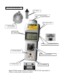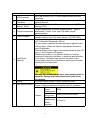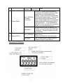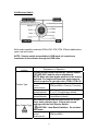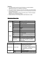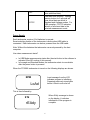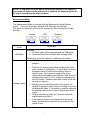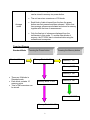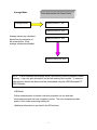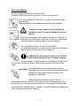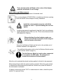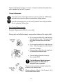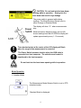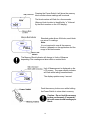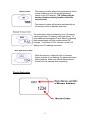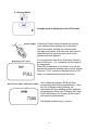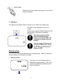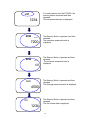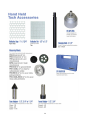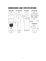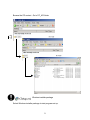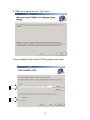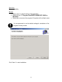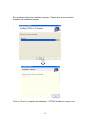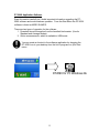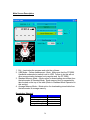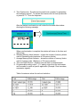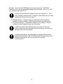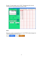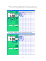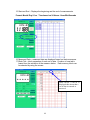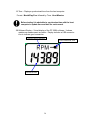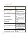
1
n
Thank you for your purchase of this Shimpo Product. This manual explains how
to operate your equipment safely and correctly. The manual covers the various
different features of the DT-209X. Kindly read this manual thoroughly before
operation as it holds important information that will help you fully utilize this unit.
Caution warning holds important safety information
Reminder: holds important key information for the product.
Warning: Laser equipped product. Observe caution
DT-209X Handheld Digital Laser Tachometer
Table of Contents
Section I – Handheld Tachometer
•
•
•
•
•
•
•
•
•
•
•
•
•
•
•
Description of Parts………………………………………………………………………….………1
Description LCD Display…………………………………………………………………….………3
Unit Selector Switch………………………………………………………………………………….4
Abbreviation of Display Table………………………………………………………………………5
Power Supply…………………………………………………………………………………………6
Measurement Modes………………………………………………………………………………...7
Flow Chart Diagram………………………………………………………………………………….8
o Standard Mode
o Average Mode
o USB Mode
Measuring Methods ……………………………………………………… ……………………….10
Mode Operation…………………………………………………………………………………….13
o Display Explanation
Memory Function…………………………………………………………………………………...17
Other Function………………………………………………………………………………………20
o Memory Deletion
Analog Output ………………………………………………………………………………………21
Replacing Batteries…………………………………………………………………………………22
Specifications……………………………………………………………………………………….23
Accessories………………………………………………………………………………………….24
Section II – Software……………………………………………………………………………………...27
• DT-209X API Section
o Software Compatibility
o Advantages of USB
o Different Modes
• DT-209X API-CD Checklist………………………………………………………………………….28
• DT-209X USB Driver Installation……………………………………………………………………29
• Application Software Installation……………………………………………………………….……30
• Main Screen Description ……………………………………………………………………….… …36
• LCD Display………………………………………………………………………………………….39
• Unit Selector Switch………………………………………………………………………………….40
• USB Mode Screen……………………………………………………………………………… ……41
• USB Mode Graph Screen………………………………………………………………………… ….51
• Standard Mode Screen……………………………………………………………………………. …53
• Average Mode Screen…………………………………………………………………………….. …57
• Display Hold…………..…………………………………………………………………………… ..62
• Troubleshooting Section ……………………………………………………………………………..63
DT-209X Parts Description
4. Contact
6. Laser Beam Opening
9. Power Switch
5. Contact Adapter
(DT-ADP-200L)
7. Display
3. Measurement Mode Selector
10. Memory Button
8. Unit Selector Switch
2. Analog Output
1. USB Connector
Model DT-209X casing is similar to standard DT-207/DT-205L with addition of
USB port, analog output, and selector switch.
1
Parts
1
2
3
USB Connector
Analog Output
Connector
Measurement Mode
Selector Switch
4
Contact Accessories
5
Contact Adapter
6
Laser Beam
Opening
7
Display
8
Unit Selector Switch
Function
Mini-USB connector for PC online measurements and data
downloads.
0 to 1-volt analog output connector for pen recorders and other
external devices.
Slide selector switch for different measuring modes. (USB,
Average, STD).
Contact attachments for contact measurements. Types of
attachments: Funnel, Cone, and FPM wheel (length
measurements).
Threaded adapter for contact measurements. It can be
installed easily on top of the laser opening. (DT-ADP-200L).
Output opening for laser diode. (Laser beam Max output: 1
mW. Continuous Wavelength: 670nm).
For Non-contact operation the reflective tape is placed on the
rotating object. When the reflective tape passes the laser a
count is generated.
Effective distance from object to be measured can be from 127
mm to 1.5m (5 inches to 59 inches).
*Measuring Conditions: On reflective surfaces, it may be
necessary to paint the shaft black, to minimize false activation
of the sensor. Reflective tape size and the radius of the
moving object should be considered to get the most accurate
reading from the tachometer.
Warning: Do not look into the laser beam opening while in
operation. Staring at the laser beam directly can cause
eye damage.
LCD main display 5digits/ Custom Words and Units.
Units of measure are selected from this switch.
Proper contact tip accessory should be used for operation.
Rotation
RPM
Speed
Measurement
Contact
Linear Speed
Measurement
M/min-yd/min-ft/min-in/min
Length
Measurement
in /ft/yd/ m
(wheel
required)
2
NonContact
9
10
Power Switch
Memory Button
Rotation Speed
Measurement
RPM
ON and OFF switch and block separator.
For standard and average mode the power
switch button is required while taking
readings. Failure to press the power button
Non- USB Mode will not permit measurements. Pressing the
(No cable
memory button while holding the power
connected)
button, allows sample points to be captured.
Releasing the power button advances the
memory per block. If the tachometer is
idle for 5 minutes, the auto power off feature
will turn on to conserve battery use.
In USB mode this switch is inactive. The
DT-209x is in the ON state while USB cable
USB Mode
is connected. Voltage is supplied from the
host computer.
Use to store data readings to DT-209X on
Non -USB Mode board memory.
Recalls stored data from the tachometer
Switch is inactive when the tachometer is
USB Mode
connected to the PC via USB port.
Description LCD Display
3
Unit Selector Switch
Multi-mode capability measures RPM, mPM, YPM, FPM, IPM and total meters,
yards, feet and inches.
NOTE: Selector switch not available in USB mode; all controls are
transferred to the software through the USB cable.
Measurement
method
Explanation of Operation
Contact measurement requires the contact adapter
(DT-ADP-200L) and the proper attachments.
NOTE: Make sure that proper position of the knob is
selected. For length and linear rate measurements
wheel is required to get right ratio. (FPM-6, FPM-12).
Contact Type
Non-Contact Type
For rotational
speed
measurements
RPM (rev/MIN) –Cone tip, Funnel tip
For speed
m/MIN - yd/MIN - ft/MIN - in/MIN
measurements
(6” or 12” circumference wheel).
For length
in / ft / yd / m (6” or 12”
measurements
circumference wheel)
Non-contact measurement requires the use of the
laser and a reflective tape. Choose the correct
settings with the Unit Selector Switch.
CAUTION: Laser Beam Radiation. Do not stare
into beam.
rotational
speed
measurement
RPM (rev/MIN)
4
Operation
• The switch selector can be turned clockwise or counter-clockwise
depending on which unit of measure is required.
• The unit of measure selected on the dial is indicated in the digital display.
• Conversion of units –measured values can be automatically converted to
the unit selector switch.
Limitation: Conversion is limited to the same group of values (example
RPM cannot be converted to inches).
• Dashes will show on the display when invalid selection is made.
Abbreviation Display Table
Setting
Unit
Display
RPM
m/M
Y/M
f/m
I/M
IN
fT
YR
m
Usb
STd
AVE
Mode
LST
M1~M10
NOO~N30
Additional Displays
Setting
Measurement
State
Display
5 figure digits
LoAd
rEAdy
Meaning
RPM-Revolutions per minute
Meters per minute
Yards per minute
Feet per minute
Inches per minute
Inches
Feet
Yards
Meters
USB mode
Standard mode
Average mode or average data
display
Last measurement recorded
Memory number in Standard Mode
Block number (Average:30 memory
blocks max, Standard: 24 memory
blocks max)
Meaning
Depending on which mode is
selected, and the range of
measurements the decimal point may
not be available. For better resolution
use USB mode and DT-209X
software.
Storing data reading
Tachometer ready to accept readings
5
FULL
CCCCC
Full memory indicator (the unit cannot
store additional data)
Clear data from memory. Holding
memory button for 5 seconds will
clear stored data per block in
Standard and Average modes. For
USB operation, CCCCC indicates
deletion of all stored data in the
selected measurement mode.
Power Supply
Each tachometer requires 2 AA batteries to operate.
Smart switching feature of the tachometer is active when USB cable is
connected. Each tachometer can be bus powered from the USB cable.
Note: Without the batteries the tachometer can work powered by the host
computer.
How does measurement starts?
•
•
In USB Mode measurements starts after the start button in the software is
activated (See API section of this manual).
In Average and Standard Modes, the tachometer starts to record data
after the power button is pressed.
When the DT-209X tachometer is turned on the following displays are shown.
RPM
Load message from the LCD
indicates program is initializing.
Preparing previously stored data
before it went to auto shut off
LoAd
This is then followed by
When rEAdy message is shown
on the display, it indicates
initialization of the program is
complete.
STd
rEAdy
6
NOTE: In USB mode recorded data is downloaded directly to the computer.
Auto power off feature of the tachometer is disabled; the supply of power for
the unit is coming from the host computer.
Measurement Mode
The Measurement Mode is changed with the Measurement Mode Selector
switch. There are three basic settings USB, Standard and Average.
The switch is located on the side of the tachometer (See Description of Parts
Section).
Average
USB
Measurement
mode
USB Mode
Standard
Explanation
Features:
• DT-209X takes online measurements via USB cable.
• Downloads data from Standard and Average Mode.
Please refer to the API manual for additional information.
• DT-209X takes measurements while the power button is
pressed.
•
Standard mode
•
•
•
There are 24 memory blocks that can be stored; each
block contains 10 data points. To store data in memory,
the power button is held and the memory button is
pressed once. This routine is repeated for every
measurement that needs to be captured. After all the 10
data points are used a “FULL” indicator is displayed on
the LCD screen. Arbitrarily less than 10 data points can
be stored in memory.
Moving from one data block to the next requires the
release of the power button. When recording is resumed
the display will show “n” followed by a number indicating
the existing memory block location, where data will be
stored.
Holding the memory button for 5 seconds clears the
stored memory per block.
If the memory button is not pressed while the power
button is activated, the data will not be stored for that
period of time.
7
Average
mode
•
The max, min, average, last and time of measurement
can be stored in memory via power button.
•
The unit can store a maximum of 30 blocks
•
Each block of data is based from the time the power
button was first pressed and then released. Within that
time average values are calculated and stored in memory
together with the time of measurement.
•
Only the final set of values are displayed from the
tachometer in this mode. To review other blocks of
memory, the DT-209X has to download data using the
software and a computer.
Flowchart Diagram
Standard Mode
Pressing the Power button
Standard Mode
Memory Block 1 “n01”
Pressing the Memory button
Memory 1 “M1”
Memory 2 “M2”
Memory 3 “M3”
•
•
•
There are 24 blocks in
Standard mode.
Each block contains 10
memory points
Total of 240 memories can
be stored.
Memory Block 2 “n02”
Memory 4 “M4”
Memory 10 “M10”
Memory Block 24 “n24”
8
Average Mode
Average Mode
Press and release the Power button
Memory Block 1 “n01”
Memory Block 2 “n02”
Average values are calculated
based from the activation of
the power button. (Only
average values are available).
Memory Block 3 “n03”
Memory Block 30 “n30”
NOTE: In both Standard and Average Mode, the memory button is pressed to recall
memory. It can only give information on the last memory block stored. To examine
other memory blocks the data should be downloaded using the USB Mode and DT209X Software.
USB Mode
Online measurements, software controlled programs can run and take
measurements while the host computer is active. The host computer provides
power in this mode conserving battery life.
(Additional information is provided in the API section.)
9
Measuring Methods
Rotational speed measurement (Contact RPM)
Example: RPM measurement using the cone tip for motor rotation.
The contact adapter (DT-ADP-200L) is attached to the tachometer
laser opening.
There are threads on the adapter assembly for easy installation.
Install the contact adapter securely until all the
threads are used. To prevent damage do not over
tighten.
Use the cone tip adapter to read shaft measurements. Slide the tip
on the shaft of the tachometer. Make sure that the notch and the pin
from the tachometer shaft is aligned to prevent slippage.
The Unit Selector Switch is turned to contact RPM.
For additional information on other settings check the Unit Selector
Switch section of this manual (Refer to page 4).
In USB Mode the Unit Selector Switch is not available.
All the controls are transferred to the host computer.
The cone adapter is slowly pressed to the rotating shaft. Make sure
that the line of contact is straight. (Most motors provide a pilot hole on their
shaft).
The power switch is pressed while taking readings.
Releasing the power button will stop measurements and
activate the 5-minute auto power off feature. (Not
applicable in USB Mode.)
When the display continues to show “0.00” no
measurements are being taken. If this happens check the power button if it is
pressed firmly or if the contact tip is making good contact with the rotating shaft.
Measured data is displayed every 1 second. (Using the software the update time
can be adjusted as fast as 0.5 second.)
10
Three decimal points will flash on the center of the display
when the tachometer is out of range.
Speed and Length Measurements
Example: Length measurement for amount of materials used.
The contact adapter (DT-ADP-200L) is installed on the laser opening.
There are threads on the adapter for easy installation.
Install the contact adapter securely until all the
threads are used. To prevent damage do not over
tighten.
Length measurement is performed using the 6-inch circumference
wheel (Standard units, FPM-6) or the 12-inch circumference wheel
(DT-209X-S12, FPM-12)
When attaching the wheel adapter, make sure
that the pin from the tachometer shaft is aligned
with the notch on the wheel.
Using the Unit Selector Switch set the knob to the suitable unit of
measure needed for the application.
For additional information refer to the Unit Selector Switch section
of this manual. (Refer to page 4.)
The Unit Selector Switch is inactive when connected
to a computer via USB cable. All changes and
controls are transferred to the software.
After the unit is selected the wheel is slowly applied to the belt to be measured.
Measurement begins after the power switch is pressed. When the power switch
is released the measurement stops and the 5-minute auto power off feature of
the tachometer is activated.
If display continuously shows “0.00” no measurement is taken, check the power
switch if it is pressed firmly.
11
Typical measurement update is 1 second. (Using the software the update time
can be adjusted as fast as 0.5 second).
Things to Remember
The rubber portion of the tip accessories (cone tip, funnel tip, FPM wheel)
may become hot and may wear out prematurely at high speeds.
Press the tachometer firmly on the moving material when using the wheel.
Do not go beyond 300mm /min.
Non-Contact Measurements
Example: Measuring the RPM of a motor shaft.
Using a piece of reflective tape to measure the rotation of the motor shaft.
•
Do not use this method for shafts smaller
than the reflective tape. The tape should
be at least the same size as the laser
beam.
•
Do not use this method for shafts that are
shiny. This may trigger the tachometer to
•
•
have false readings.
Remove water and oil from the shaft prior
to attaching the reflective tape.
The unit selector switch is turned to
Non-contact RPM.
The Unit Selector Switch becomes
inactive when the USB cable is
attached from a computer.
The laser beam opening is pointed towards the
position of the reflective tape.
Effective distance is 50mm -1.5m (2 inches - 14 ft)
from the laser beam outlet.
12
CAUTION: Do not look into the laser beam
opening while in operation. Staring into the
laser beam can result to eye damage.
The power switch is pressed while taking
readings. The Mode Selection Switch is set to
either Average or Standard Mode.
The display will show “ 0 “ when measurements
stop.
Measured data is displayed every second (On
slower readings less than 60 RPM the display will
update approximately every 1- 10 seconds).
Three decimal points at the center of the LCD display will flash
when the range of the measurement is exceeded.
The Power Switch becomes inactive when the USB cable is
connected to a host computer. The selection and control is
transferred to the host computer.
Do not look into the laser beam opening while in operation.
Mode Operation
1. Standard Mode
The Measurement Mode Selector Switch is set to STD
(standard mode).
Standard Mode is displayed.
13
Pressing the Power Switch it will show the memory
block number where readings will be stored.
The block number will flash for a few seconds.
(Memory block location is identified by “n” followed
by the block number on the LCD display).
Standard mode allows 24 blocks; each block
can store 10 readings.
Note:
It is not required to use all the memory
blocks; it depends on the application and the
usage of this tachometer.
The Memory Block Indicator will change to Units of Measure
depending if the readings are taken within a certain block.
Unit of Measurement is displayed on the
LCD screen. The upper display indicator
will flash while taking measurements.
The display updates every1 second.
Push the memory button once while holding
the Power Switch to store data in memory.
Caution: Do not hold the memory
button continuously (5 seconds);
this will erase stored readings per
block.
14
The memory location where the measurement will be
stored is shown on the Unit and Measurement
section of the LCD display. (“M” followed by the
number indicates memory location inside the
current block).
The memory number will advance automatically as
the memory button is pressed each time.
The tachometer will stop advancing once 10 memory
values are stored (10 memory values per block). To
store additional readings the Power Switch is released
then pressed again until the number behind “M”
changes. It will show a FULL indicator on the LCD
display once 10 readings are stored.
When the memory, mode and units of measure
display indicator is not flashing, the tachometer stops
taking readings. Make sure that the Measurement
Power button is pressed while measuring.
Display Explanation
15
2. Average Mode
Average mode is displayed on the LCD screen
Pushing the Power Switch will show the memory
block number where readings are to be stored.
The block number will flash for a few seconds.
Average mode allows 30 blocks total, each block is
dependent on the time the power switch is first
pressed and then released.
It is not requried to use all the 30 memory blocks to
avail of this mode. It is dependent on the usage of
the tachometer.
When N30 is displayed on the screen, the unit has
reached the maximum allowed memory block number.
When the “FULL” indicator is displayed on the LCD
screen, no additional readings will be stored.
Unit of Measure Indicator (RPM) will flash
continuously while taking measurements. Once
the Unit of Measure stops flashing, the
tachometer will stop updating and no additional
measurements will be read. Pressing the Power
Switch will advance the memory block location
and resume measurements.
The display updates every 1 second.
16
Releasing the Power Switch will trigger the auto shut off
feature to activate.
3. USB Mode
The Measurement Mode Selector Switch is set to USB mode (USB mode).
The USB mode is displayed on the LCD
screen.
Please refer to the DT-209X API Section of this
manual under USB Mode for additional
information.
The Power switch and Unit
Selector Switch becomes
inactive from the DT-209X. All
controls are transferred to the
host PC.
The auto power off feature will
not work in USB mode. Power
for DT-209X is switched from
battery to USB.
Memory Function
The DT-209X can store measured data on the tachometer. Memory recall after
the auto power off is activated is possible.
1. Standard mode
RPM
1234
The figure on the left indicates that the
tachometer stops measuring. The unit of
measure stops flashing when the power
button is released.
17
LST
1234
RPM
MAX
7200
RPM
MIN
60
AVE
4500
M1
1234
To recall memory from the DT-209X, the
memory button is pressed and then
released.
The last measured value is displayed.
The Memory Button is pressed, and then
released.
The maximum measured value is
displayed.
The Memory Button is pressed and then
released.
The minimum measured value is
displayed.
The Memory Button is pressed and then
released.
The Average measured value is displayed.
The Memory Button is pressed and then
released.
The first stored data is displayed.
18
M10
2345
LST
1234
The stored data in the tachometer can be
recalled each time the memory button is
pressed (M1→M2 etc.). (This is only
applicable to the last Memory block used
and in Standard Mode).
Pressing the Memory Button after M10 will
cycle back the process to M1.
Only the last memory block is accessible
for review. To review all the blocks stored,
it is necessary to download the stored
data using the USB cable and software.
2. Average Mode
RPM
When the Power Button is released the
DT-209X stops measuring.
1234
The Memory Button is pressed.
LST
1234
RPM
MAX
7200
The last measured value is
displayed.
Data for calculations are not
accessible. Only the average
value can be recalled, together with the
LAST, MAX, and MIN readings.
The Memory Button is pressed and then
released.
The maximum measured value is
displayed.
19
RPM
MIN
60
AVE
4500
The Memory Button is pressed and then
released.
The minimum measured value is
displayed.
The memory button is pressed and then
released.
The calculated average value is displayed.
Pressing the memory button cycles back
to LST. Note: Only the last Memory block
is accessible for review. To review all
blocks download data to the DT-209X
software
Other Functions
Memory deletion
Pushing the Memory Button for 5 seconds
or more clears the last memory block
stored in the tachometer.
RPM
1234
N08
The LCD display will show “CCCCC”
indicating that one block of memory has
been deleted.
CCCCC
20
Clearing all the stored memory blocks requires manual
deletion from the tachometer. (Example: To clear 23 blocks
of memory requires erasing the memory 23 times.)
Memory deletion: The tachometer deletes the last memory block used and
shifts down one block at a time, starting from the last going down to the first
block stored.
N24
N23
N22
N21
N04
N03
N02
N01
delete
N23
N22
N21
N04
N03
N02
N01
From the software all the 23 data blocks can be erased all
at once by selecting “Clear Device Memory”.
Analog output function
This tachometer has an analog 0 – 1V output that can be utilize for chart
recorders and data acquisition cards.
At full range the output delivers an analog 1–volt signal.
21
Maximum Values Allowed
Unit
Full range
Non contact
99,999
RPM
m/min
3810.0
ft/min
12,500
in
99,999
Yd
99,999
Unit
Full range
Contact RPM 25,000
yd/min
in/min
ft
m
4617.0
99,999
99,999
99,999
Replacing batteries
LO BAT flashes on the
LCD display.
This indicates that battery
needs replacement.
For better performance
use new Batteries.
LO BAT
RPM
9999.9
Open battery cover located on the bottom of the
tachometer.
Insert 2 new batteries; a sticker can be viewed
from the case indicating proper polarity.
Do not mix old and new batteries; this may cause
leakage on the battery compartment.
Do not expose battery compartment to liquids, this
may cause a short inside the terminals damaging
your tachometer.
Prior to storage the battery inside the tachometer
should be taken out and placed on the carrying
case.
22
Specifications
Measurement
mode
Measurement
method
Model
Standard mode
Average mode
USB Mode
Contact
Non contact
Indicator
Contact
Non contact
Rotational
speed
Speed
Contact
Length
RPM
RPM
m/min
yd/min
ft/min
in/min
In
ft
yd
m
Contact
Measurement
accuracy
Non contact
Measurement time
Standard Mode
Memory
function
Average Mode
USB Communication
Analog output function
Auto power off feature
No USB Cable
Connected
USB Cable Connected
Case material
Externals size
Mass
Ambient temperature of use
Ambient temperature of use
Power supply
Accessory
Standard
Option
Content
DT-209X (6-inch cir wheel), DT-209X-S12 (12-inch cir wheel)
Measurement with memory switch
Mean value measurement for measurement period
Measurement by computer
The contact adapter and headers are used on the rotating body.
The laser beam is directed towards the reflective tape. Reflection from the
reflective tape is used fore measurement. Measurement distance
50mm -1.5m
5DigitLCD Character amount 12mm
0.8
25,000
6.0
99,999
0.11
3,810.0
0.13
4,167.0
0.4
9,999.9
5
99,999
1.0
99,999
0.1
99,999
0.02
99,999
0.02
99,999
0.8
9999.9rpm
±1rpm
10,00
25,000rpm
±0.006% of display value±1rpm
0
6
8300rpm
±1rpm
8301
25,000rpm
±2rpm
25,00
99,999rpm
0.006% of display value ±1rpm
1
Approximately 1 second
Ten measurement points per blocks, in addition (LAST,
24Blocks
2
MAX, MIN, MEAN values, and measurement date
Final value, maximum value, minimum value, mean
30Blocks
value, and measurement date 2
USB1.1
0 to+1V Full Range
5 minutes (This feature is turned off when measurement selector switch is
set to USB and USB cable is connected to a PC.).
Two 1.5V AA batteries
Power supplied through USB cable, switch from battery to USB at this mode.
Aluminum die cast
Length203×Wide63×Thickness 46mm USB excluded. Cable.
400g (Batteries included.)
0 – 45 C (Moderate humidity)
2 cone adapters, 1 funnel adapter, 1 3-1/2” extension shaft, USB cable
(Length: 36 inches), carrying case, 1 master wheel (6-inch circumference
wheel), software CD-R1, reflective tape, 2 AA alkaline batteries,
Analog output cable
It is not possible to read date and time through the handheld tachometer. Data should be
downloaded to a PC to view the date and time of the test.
23
24
25
26
DT-209X API Section
Thank you for your purchase of the DT-209X handheld tachometer.
Please read this section carefully before using the DT-209X software.
This section covers the installation and description of the software for the DT209X.
Keep this manual and software safe for future reference.
Software Compatibility
•
•
•
•
•
The software is compatible with Windows XP and 2000.
Separate USB drivers are provided and can be found in your installation
CD.
Display size: 480 X 640 or greater; Recommended 600 X 800
Display Colors: 256 colors or greater; Recommended 65536 colors.
USB 1.1
Advantages of USB
•
•
•
•
•
•
Direct data acquisition (online measurements).
Data transfer to spreadsheets (e.g. Excel).
Transfer of stored data from the tachometer (Average and Standard
Mode).
Bus powered through the USB cable. (DT-209X switches from battery
power to bus power).
Graphic analysis, while data is stored.
Multiple data sets
Different Modes
Standard Mode – Acquire standard data stored from the DT-209X memory.
From this mode data are downloaded and separated by sets based on the
number of memory blocks. Maximum of 24 blocks, each block can hold 10 data.
Average Mode – Acquire average data stored from the DT-209X memory. From
this mode data are downloaded and listed as it have occurred, maximum of 30
memory blocks.
USB Mode – Direct acquisition of data from the DT-209X. From this mode
online measurement is possible. The tachometer switches the battery to USB
power provided by the host computer. Graph function is available, allowing the
observation of data, as it is acquired from the DT-209X.
27
Observe caution when using this software and mounting the tachometer.
Serious damage to equipment is possible when misused.
DT-209X API Manual CD Checklists
Included in your DT-209X package is a copy of the installation program for the
DT-209X operating software. Each CD contains the following files.
Folder
Driver
File name
DT209XUSB.dll
WindowsXP DT209XUSB.inf
DT209XUSB.sys
DT209XUSB.dll
Windows2000 DT209XUSB.inf
DT209XUSB.sys
autorun.inf
DT209X.exe
DT209X
init.reg
InstMsiA.Exe
PC_API
InstMsiW.Exe
Main.ico
PCSetup.msi
Setup.Exe
Setup.Ini
Content
DLL of USB file.
inf of USB file.
sys of USB file.
DLL of USB file.
inf of USB file.
sys of USB file.
Setup information on the
application.
Execution of the application
file.
Registration of the
application file.
Installation of the
application file.
Installation of the
application file.
Icon of the application file.
Installer of the application
package.
Installation of the
application file.
Composition equipment of
application file.
The DT-209X is compatible with Windows XP and 2000. It is strongly
recommended that you close all open programs before installation.
28
DT-209X USB Driver Installation: (WINDOWS XP)
Included in your package is a USB cable.
Attach USB cable to the handheld tachometer and host computer as shown
below.
Windows will automatically detect the presence of new hardware.
Insert software CD and click on “Next”. Windows will search for available drivers.
Choose the driver suited for your operating system (Windows XP or Windows
2000).
29
Click next. Installation process will continue. After installation is completed the
following window will be displayed.
Click on “Finish” to complete the installation of the DT-209X USB driver.
Separate installation is required for computers that will use multiple USB
ports. Follow same procedure for each USB port that will be used.
Application Software Installation
Please follow the following procedures. It is strongly recommended that you
close all open programs before installation.
30
Browse the CD content. Go to PC_API folder
Windows installer package
Select Windows installer package to start program set up.
31
DT-209X set up wizard will open. Click “Next>”
Choose installation folder where DT-209X program will be stored.
32
Disk Cost
Space availability.
Browse
• Allows users to select location of the application
• Default set up: C: \Program Files\NIDEC-SHIMPO\DT-209X for
Windows\
• Select who can access the program (Computers with multiple users).
It is recommended to use the default settings for installation of the
program for easy access.
Click “Next>” to start installation.
33
Set up wizard will start the installation process. Please allow a few minutes to
complete the installation process.
Click on “Close” to complete the installation. DT-209X software is ready to use.
34
DT-209X Application Software
Read this section carefully as it holds important information regarding the DT209X software and mode windows operation. From the Start Menu the DT-209X
software is listed as NIDEC-SHIMPO.
There are two types of operation for the software
1. Download stored information from the handheld tachometer. (Use for
Standard and Average Modes).
2. Online measurements, which is available in USB mode.
You can create a shortcut to the software application by dragging the
DT-209X Icon to your desktop from the list of programs on your Start
menu.
DT209X for PC Windows.lnk
35
Main Screen Description
1. Exit – terminates the program and exits the software
2. USB Mode – Online measurement (Note: Make sure that the DT-209X
Handheld mode selector switch is set to USB. Failure to do this will not
allow communication between host computer and the DT-209X).
3. Standard Memory Mode – Mode option for downloading stored data from
the tachometer in Standard Mode. Each memory block is separated by
tabs located on the top of the table (Refer to Standard Mode Operation in
this section).
4. Average Memory Mode – Mode option for downloading stored data from
the tachometer in average memory.
Keystrokes Shortcut
Tab Name
Key combination
Alt + E
Exit
Alt + U
USB Memory Mode
Alt + S
Standard Memory Mode
Alt + A
Average Memory Mode
36
5. Time Synchronize - Synchronize time with host computer for generating
time stamping reports. To activate this feature click on time synchronize
or press ALT + T from the keyboard.
After the feature is activated you will notice the time and date window
showing the following message.
6.
7.
8.
9.
When synchronization is complete the window will return to the time and
date format.
Standard Memory block Indicator – shows the number of memory blocks
used in Standard mode (maximum of 24 memory blocks).
Average Memory Block Indicator – shows the number of memory blocks
used in Average mode. (Maximum of 30 memory blocks).
Time and Date Window – displays time and date of measurements.
Programmable analog output - +1 V analog output from the tachometer
can be scaled to match a specific application (Example: Chart recorders,
comparator signals).
Table of maximum values for each unit selection
37
Example: In Non-contact RPM Maximum expected speed is 1,000 RPM.
Entering 1,000 in the programmable analog output will scale 1V from 0 to 1000
rpm. (500 rpm will output 0.5 V).
If the set rpm exceeded the analog output, it will maintain 1V. If the
unit is change it defaults back to maximum value based from the Table
of Maximum Values found on page 37.
10. Software display – displays values as measured by the tachometer.
Reflects the unit of measure, USB connection status and data points.
11. Unit Selector Switch – Unit Selector Switch for the software. Units of
measure can be changed directly from this option.
In USB mode and online measurements, the position of the unit
selector switch from the tachometer becomes inactive. All selections
are performed from the software.
In downloading data for both Standard and Average Mode, set the
mode selector switch to USB. DT-209X will be bus powered from the
USB port (disabling the auto shutoff feature to maintain
communication).
38
Virtual Software LCD Display
Troubleshooting USB Communication
• If USB communication cannot be establish check USB cable from the
tachometer and the host PC.
• If after all connections are checked, communication is still inactive, unplug
the USB cable from the PC port and plug it back in, Windows should be
able to detect the cable.
• If after the above conditions are made and still no connection, restart the
program.
39
Unit Selector (Software)
Selecting units of measure can be changed easily from the software. Provided
on the main window is a virtual copy of the handheld unit selector switch.
The selected setting is highlighted in RED; changing the settings would require
clicking the mouse and dragging the red highlight to the appropriate setting.
The software overrides the Unit Selector Switch from the tachometer.
It is completely autonomous; all controls are transferred to the
software.
Key feature for online measurements: The tachometer can be set to almost any
place in the production line. Handheld tachometer is bus powered by the USB
making it ideal for process monitoring. As long as the host computer is “ON” the
tachometer will work (provided that the tachometer is set to USB mode).
CONTACT MEASURING
YARDS PER MINUTE
NON-CONTACT RPM
40
USB Mode Screen
USB mode screen display explanation
Make sure that the DT-209X handheld tachometer is set to USB mode on the
selector switch. Any other settings will not allow the software to recognize the
tachometer.
18
1
17
16
2
19
3
4
14
5
6
13
15
12
7
8
10
11
9
1. Main - Return to main screen button (ALT + M)
2. File Save – Save button, opens a Window for saving measured values.
Files are saved based on the open set of data on the screen. (ALT + F).
41
Files are saved in CSV format, which can be opened by spreadsheets.
Sample of data opened in Microsoft Excel (USB Mode).
Example: Tab of data displayed on the screen in USB mode is the only
set of data that will be saved on file, each tab is saved separately. In
standard mode all 24 blocks are saved, and in Average Mode all 30
blocks are saved.
Sample of data opened in Microsoft Excel (Average Mode).
42
Sample of data saved in Excel (Standard Mode).
3. Restore – file retrieval button. Open saved file from the computer.
(Shortcut keystroke ALT + R)
43
File restore window
The letter “R” identifies file restored on the list of data shown from the
screen.
4. Start - measurement starts (Only applicable in USB mode). Keystroke
shortcut “ALT + S”.
If software locks as shown below, please check the mode selector switch. Set
switch selector to USB mode. This will allow control back to the software.
44
5. Print – Print function from the software allows transfer of images displayed
from the screen to a local printer.
Keystroke shortcut “ALT + P”.
6. Measure – This button allows the creation of a new tab or set of data. It
enables the “Start Button” to be active at the beginning of each test. If
Measure is not selected, the Start button will not be active. Keystroke
shortcut “ALT + M”
7. Clear Block – Deletes selected memory block from the set of online
measurements. Once selected, a window will appear on the middle of the
screen confirming the operation. After verification is complete, the
displayed tab or set of data is deleted and moved down one memory
block. Keystroke shortcut “ALT + B”.
Confirmation Window. In USB memory block deletion is done by set.
8. PickupRecord – selects highlighted set of data (drag and select data with
mouse). Pick up Record, deletes all measured values except the set that
are highlighted. Keystroke shortcut “ALT + R”.
Highlighted selected data using the Pickup Record function.
45
Confirmation screen, indicating unselected data will be erased
9. Graph – Opens graph in another window, only available in USB mode.
This feature allows observation of actual data while it occurs during
measurement test. To return to table of measured values select “Close”
located on the middle of the window.
10. Measurement Interval – option to set the measurement interval of the
tachometer. This option allows change of measurement interval from
50msec to 5,000msec (5 seconds). (Options: 50msec, 100msec,
500msec, 1,000msec, and 5,000msec).
11. Display Refresh Interval – allows variable intervals of measurement to be
displayed. This option is active before and after the measurements.
Table of values can be displayed from 0.05sec – 30 sec.
(Options: 0.05sec, 0.1sec, 0.5sec, 1sec, 2sec, 5sec, 10sec, and 30sec)
Display refresh interval automatically detects error in selection whenever
an option is invalid. It compares value from the selected measurement
interval. (Example: Measurement interval is selected at 100msec, and
user would like to have a display refresh interval of 0.05 sec, this entry will
be invalid because the display would need to be at least the same speed as the
measurement interval or slower.).
12. Measurement Condition – Start, Limit and Alarm. Allows setting conditions
to be monitored within a specific range.
Options
Start
Trigger
Limit (sec.)
Alarm
Upper
Alarm
Lower
Explanation
Measurement begins when the measured value is
more than the value entered in the start trigger box.
Measurement time is set.
Measurements automatically stop after the set time
is reached.
When value is set to 0, it can measure infinitely as
long as the host computer is on.
It warns if the measurement data becomes more than
the set value.
It warns if the measurement data becomes lower
than the set value.
46
Example: The start trigger is set to 10,000. The tachometer will only start
recording values when measurements exceed 10,000.
Alarm
Whenever an alarm is generated the color of the DT-209X taskbar changes; the
computer generates a buzzing sound.
Normal
Alarm
47
13. Maximum, Minimum, and Mean Value – The maximum, minimum and
mean value are displayed based from the recorded data on the table.
14. Records – Displays number of measured data recorded.
48
15. Start and End – Displays the beginning and the end of measurements.
Format: Month/ Day/ Year Time based on 24 Hours: Hour/Min/Seconds
16. Measured Data – measured data are displayed based on their occurrence.
17. Block Tab – block separation of each set of data. Creation of new tab is
based from the activation of the measure button. Each memory block can
be selected by using the mouse.
Block Tab No.7, if an “R” is
displayed this means that a
set of data is restored or
retrieved.
49
18. Time – Displays synchronized time from the host computer.
Format: Month/Day/Year followed by Time: Hour/Minutes
Before testing it is advisable to synchronize time with the host
computer to update time and date for each record.
19. Software Display – Virtual display of the DT-209X software. It shows
updates as measurement are taken. Display includes a USB connector
icon to indicate good connection.
Selected unit of measure
USB Connection Icon
Measured Data
50
USB Mode Graph Screen
This section describes the parts and functions of the Graph Screen under USB
mode.
5
10
1
3
4
2
9
7
6
8
1. Close – closes the graph screen and moves back the screen to the USB
table (Keystroke shortcut ALT + C).
2. Print – prints the graph as displayed from the screen. Size of print is
dependent from the settings of the printer. Print button is inactive when
measurements are in progress. To print the graph, the graph screen
should be closed and the measurements should be stopped. (Keystroke
shortcut ALT + P).
3. Auto – vertical display control for
measurements. Selecting values sends the
graph to a particular vertical range. Side
scroll bars are also available for utilization.
Recommended that this is set to auto for
optimum view of the graph.
51
4. All – horizontal display control, time axis.
Setting
Explanation
It automatically sets time present while the
All measurements are in progress. It is also the time after all
measurements are stopped.
Setting Limit of the USB main screen
Limit The same range setting is set to “All” when Limit is set to
0.
10sec.
Selectable time range of each value, optional scroll bars
100sec.
are provided for manual view.
300sec.
5. Tab – numbered tabs separate sets of data captured from the tachometer.
Each set has a corresponding graph that can be viewed from the USB
Graph Screen.
6. Measurement data – horizontal line tracing the measured values as it
occurs. This green line is always changing, based from the changes in
measurement.
7. Maximum Value Bar – horizontal line tracing the maximum value
measured.
8. Minimum Value Bar – horizontal line tracing the minimum value measured.
9. Max, Min, Average Value Bar – Small table located on the upper left hand
corner of the graph. This bar is a quick summary of the maximum,
minimum and average values of the data measured.
10. Time – Time recorded when the measurements took place. Format as
follows: MM/DD/YYYY, followed by time in 24-hour format HH:MM.
52
Standard Mode Screen
Explanation of the Standard mode screen:
In this mode data can be downloaded from the DT-209X memory.
Memory tab separates each memory block.
Initial Screen of Standard Mode
1
2
3
4
5
6
Screen after data are downloaded
9
13
8
2
7
11
10
12
53
1. Main – returns to the main screen (Shortcut keystroke ALT + M).
2. File Save – Downloaded data from the DT-209X is saved in CSV format.
(Shortcut Keystroke – ALT + F).
Create name of file for the set of measurements. File save is inactive when there
is no data available for download.
The CSV file can be directly imported to spreadsheets like Microsoft Excel.
CSV file is stored by the following formats.
"Memory Block No.","Start","Stop","Unit","Memory No.","Value","Time" ←Set
each name
1,06/07/2004 12:54:26,06/07/2004 12:54:42,"RPM",
Memory Block 1
,,,,1,120,21:49:11
← No.1 Measurement data
,,,,2,306,12:54:31
←No.2 Measurement data
,,,,3,196,12:54:36
,,,,4,237,12:54:38
,,,,5,206,12:54:40
←No.5 Measurement data
2,06/07/2004 12:54:44,06/07/2004 12:54:57,"RPM",
Memory Block 2
,,,,1,37,12:54:42
,,,,2,280,12:54:48
,,,,3,157,12:54:52
,,,,4,173,12:54:54
←Set date No.1 Measurement data
←No.2 Measurement data
←No.4 Measurement data
54
3. Restore – opens previously saved file. From the screen the restored file has an
“R” Tab. (Shortcut Keystroke ALT + R).
4. Download – download function from the software. This allows transfer of stored
data from the Tachometer to the software. (Shortcut Keystroke ALT + D).
Numbered tabs separates each memory block.
5. Print – print function for the table of values. Size of print is dependent on
the attached printer settings. (Shortcut Keystroke ALT + P).
6. Clear Device Memory – stored data from the tachometer is cleared.
CCCCC is displayed from the tachometer LCD screen once confirmation
is complete. Shown below is the confirmation window for the clear device
memory to proceed. Selecting “YES” opens the save file window,
selecting “NO” opens a confirmation window, selecting “CANCEL”, exits
out the clear device memory function.
It is necessary that there is connection with the DT-209X and the host
computer for the Clear device memory to work.
Once “OK” is selected the stored data from the DT-209X is cleared. No
further retrieval of previously stored data is possible. Selecting Cancel exits
the Clear device memory function.
55
7. Measurement Data – measured values stored in each memory block is
displayed.
8. Block Tab – Memory block separation. Each tab corresponds to a set of
data stored per memory block. In Standard Mode, there are 24 Blocks or
24 Tabs possible.
9. Scroll – Advances screen values left or right. Useful when screen is
minimized.
10. Max, Min, and Ave – quick summary of displayed data. Maximum,
minimum and average values are calculated and displayed per set of data
displayed from the software screen.
11. Records – number of data displayed from the table.
12. Measurement Time – displays the time from the beginning to the end of
each measurement. Format of display MM/DD/YYYY, followed by time in
the 24 hour format HH:MM:SS
13. Time – Synchronized time with the host computer.
56
Average Mode Screen
Average mode screen description and explanation.
Average Mode screen initial window prior to download
11
1
2
3
4
5
6
Average Mode Screen after data are downloaded
2
9
8
7
10
57
1. Main – returns to the main screen. (Shortcut Keystroke ALT + M)
2. File Save – Saves downloaded data from the tachometer. File save button
is inactive when no downloaded data is available. Data are saved in .CSV
format, which can be imported directly to spreadsheets like Microsoft
Excel. (Shortcut Keystroke ALT + F)
File save window
The CSV file is stored in this format.
"Memory Block No.","Start","Stop","Last","Max.","Min.","Ave.","Unit"
1,03/20/2004 09:17:41,03/20/2004 09:17:46,386.4,3494.4,386.4,2717.4,"RPM" Block No.1
2,03/20/2004 09:17:48,03/20/2004 09:17:51,93.3,93.3,93.3,93.3,"RPM"
3,03/20/2004 09:18:06,03/20/2004 09:18:11,1.16,1.16,0.88,1.12," m "
4,03/20/2004 09:18:21,03/20/2004 09:18:25,0.56,0.56,0.32,0.54,"YRd"
5,03/20/2004 09:18:57,03/20/2004 09:19:00,0.32,0.32,0.04,0.20,"YRd"
6,03/20/2004 10:10:48,03/20/2004 10:10:55,6.17,122.70,6.17,76.19,"m/M"
7,03/20/2004 10:11:39,03/20/2004 10:11:46,0.82,0.82,0.02,0.48,"YRd"
Block No.9
8,03/31/2005 06:58:47,03/31/2005 06:59:06,13486,14404,8185.8,11912,"RPM"
9,03/31/2005 07:07:14,03/31/2005 07:07:21,4403.9,4407.4,2740.9,3744.0,"RPM"
3. Restore – retrieves previously measured data for review. Select Average
file from the open window for review.
(Shortcut Keystroke ALT + R).
Stored CSV files from different modes are not accessible to the wrong
window. Example: CSV file saved in USB mode is not accessible for
retrieval from the Average or Standard Mode Screen.
58
Restore File Window
4. Download – download saved data from the DT-209X. All blocks are
displayed based from their occurrence. (Keystroke shortcut ALT + D).
5. Print – print function for the displayed table. Size of print out is dependent
on the attached printer settings. (Keystroke shortcut ALT + P).
6. Clear Device Memory – erases stored data from the tachometer. Once
clear device memory is selected, the data from the tachometer cannot be
retrieved further.
Selecting the clear device memory opens a dialogue window informing the
user if the data displayed is not yet saved.
Selecting “YES” opens the File save window; selecting “NO” opens a
confirmation window, selecting Cancel exits out of the Clear Device
Memory Function. Shown below is the confirmation window.
59
Once “OK” is selected, all the Average mode stored data from the tachometer
are erased, CCCCC is displayed from the DT-209X LCD display.
No further retrieval is possible.
7. Data and date of Measurement – displays the recorded average including
the beginning and end of each memory block. This information changes
based on the highlighted data block. Format of information: 24-hour time
format HH:MM:SS, followed by Last, Max, Min, Ave, and Unit.
8. Max, Min, Ave – quick summary of the data block selected from the list.
60
9. Blocks – Displays number of memory blocks downloaded from the
tachometer.
10. Measurement Time - displays the beginning and end of each memory
block. This information changes based on the highlighted data block.
Format of information: MM/DD/YYYY, followed by the 24 hour time format
HH:MM:SS.
11. Time – Synchronized time based from the computer. This reflects the
time when the data is accessed from the tachometer.
61
Display Hold:
This feature is an enhancement to the DT-209X software, designed for users
which requires the ability to limit the amount of time the tachometer holds the last
reading after the source of the signal ceases.
The Display Hold feature is useful for applications that need to show
deceleration and immediate stop.
Specifications:
Range: 50 – 99,999 msecs
Feature only available in USB mode
Default setting: 0 (same as 10,000 msec).
Limitation of Feature:
• The Display hold feature should be set at least twice as much as the
Measurement Interval Value. If the values are set the same there is a
possibility that the lower readings (less than 100 RPM) may not be
recognized depending on how fast the Measurement Interval Value is set.
•
If setting is set below 50 msec, the software will automatically adjust it to
10,000 msec (10 seconds).
•
For Low RPM it is recommended that the Display Hold setting should be
set to a minimum of 1,000 msec (1 second).
•
If the tachometer is reading “0 “ for speeds less than 100 RPM please
adjust the Display hold value.
Location of the Display hold Feature as shown by the arrow.
62
Troubleshooting Section
Problems
Solution
Check mode selector switch. Set to USB
Software would not start, “Start” button and “Download” MODE. Check cable connection and USB
Icon.
button inactive.
Computer found new hardware, but could not find
Uninstall and reinstall DT-209X USB Drivers,
compatible drivers
check the CD included in your Kit.
Program is installed under the name "NIDECSHIMPO". Access list of programs from the
Could not find software after installation
Start Menu.
Control of the tachometer is transferred to the
DT-209X, the laser would not activate until
Start is pressed under USB mode.
Laser is not visible after the DT-209X is connected to
WARNING: Do not stare into the laser
the PC
opening. Laser beam harmful to the eyes.
Check the mode selector switch: for portable
and outside measurements the tachometer
needs to be in Standard Mode (STD) or
Average Mode (AVE). For online
measurements the DT-209X needs to be in
Unit selector switch not working.
USB.
Before storing the DT-209X make sure that
the mode selector switch is not set to USB
mode (When set to USB mode the tachometer
will not allow the auto power off feature to
activate). Make sure that the power button is
Battery discharges earlier than expected.
not pressed.
Check the polarity of connectors; it should
deliver a 0 to 1 V analog output proportional to
Analog output not working.
the reading.
Check other modes for opening the file. The
file saved in Average mode cannot be open in
Could not open saved CSV file
Standard or USB Mode.
Check printer connection. If the button is
inactive close graph window and press STOP.
(Graph cannot be printed while measurement
Could not print graph
is taking place).
There are some versions of Windows 2000
that does not allow printing from the DT-209X
software, save and open CSV file in Microsoft
Error in printing table and graph
EXCEL and print from there.
While the software is open, unplug and plug
back in the USB cable until the USB Icon
USB cable plugged in, but there is no connection
indicator establishes connection.
Uninstall and reinstall DT-209X USB Drivers,
check the CD included in your Kit. Choose the
right operating system for your Computer
Windows XP or Windows 2000. USB cable
Could not establish connection with the DT-209X
maybe damaged.
63
Measured value is divided by 2
While storing values it shows "CCCCC"
Could not measure Yards, feet, inches and meters per
minute
There are two versions of the DT-209X,
Standard Version DT-209X is set for 6 inch
circumference wheel, and DT-209X-S12 is set
to 12-inch circumference wheel. Check the
front label for proper wheel attachments.
The memory button was pressed for 5
seconds.
These linear rate measurements are available
in contact mode using the wheel attachment.
These measurements are available in contact
mode, using the wheel attachment.
Check battery orientation and reinstall.
Could not measure length
Brand new batteries no display.
While using the software, could not see values stored on
the table immediately.
Check the trigger setting values.
Found new hardware icon appears every time the DT- Different USB port. For every USB port that
209X is plugged in to the computer. (Even after previous will be used, the USB driver is required to be
installation of USB driver was successful.)
installed.
Useful Links:
For inquiries email us at [email protected]. Our website address is
www.shimpoinst.com.
Tel No. 1-800-237-7079.
Check our website for additional Shimpo Products and current product
updates.
For applications check our application notes section under the Resource
Center.
64