1
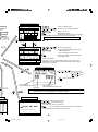
Mitsubishi Electric Air-conditioner Network System
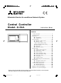
Central Controller
Model: G-50A
Instruction Book
Contents
ON/OFF
CENTRAL CONTROLLER
G-50A
1.
2.
3.
Safety precautions ...................................................... 1
Product features ......................................................... 2
Functions .................................................................... 4
3-1 Specifications .................................................. 4
3-2 Display Screen ................................................ 8
4. User operation ......................................................... 10
4-1 Operation condition monitor ......................... 11
4-2 Operation setting .......................................... 12
4-2-1 Group operation setting ........................ 12
4-2-2 Collective operation setting .................. 16
4-3 Timer operation ............................................ 19
4-4 Malfunction ................................................... 23
4-5 Current time setting ...................................... 24
5. Initial setting ............................................................. 25
5-1 Shifting to initial setting menu ...................... 25
5-2 M-NET address setting ................................ 25
5-3 Function setting ............................................ 26
5-4 Group configuration setting .......................... 27
5-5 Interlocked operation setting ........................ 29
5-6 Group name setting ..................................... 31
5-7 User setting .................................................. 34
5-8 IP address setting ........................................ 35
5-9 Initial setting tools connection function ........ 35
6. Maintenance ............................................................ 36
6-1 Refrigerant system monitor .......................... 36
6-2 Malfunction log monitor ................................ 37
7. External input / output function ................................ 38
7-1 External input function ................................. 38
7-2 External output function ............................... 39
Appendix 1: Initial setting (abridged) ............................. 40
Appendix 2: User operation (abridged) ......................... 42
Before using the controller, please read this Instruction Book carefully to ensure proper
operation. Keep this manual for future reference.
WT03945X02_En_Cover
1
07.3.23, 8:11 PM
1. Safety precautions
Before using the controller, read the Safety Precautions section carefully to ensure proper operation.
These safety precautions must be observed by anyone who operates the central controller at all times.
Keep this Instruction Book and Installation Manual for future reference. Make sure both this Instruction Book and the
Installation Manual are given to the next user.
Safety symbols used in this manual
WARNING
This symbol indicates that failure to follow the instructions exactly as stated poses the risk of
serious injury of death.
CAUTION
This symbol indicates that failure to follow the instructions exactly as stated poses the risk of
injury or damage to the controller.
WARNING
● Have the unit professionally installed.
● Ask your dealer or an authorized technician to
move the controller.
Improper installation by an unqualified person may result in
a risk of electric shock or fire.
● Make sure the controller is securely mounted so
Improper installation may result in electric shock or fire or
damage to the controller.
● Controllers must be disposed of properly.
that it will not fall.
Contact your dealer for proper disposal procedures.
● Make sure that the controller is connected to a
● Do not attempt to modify or repair the controller.
properly rated power supply to avoid fire or
damage to the controller.
Modification or improper repair may result in electric shock
or fire. Consult your dealer when repairs are necessary.
● Do not remove the cover during operation.
● Stop the operation immediately and notify your
Contact with electrically charged parts on the controller
cause skin burns or other types of injury.
dealer if an error code is displayed and the controller
does not operate, or when any abnormality is
noticed.
● If any abnormality is noticed (e.g., burning smell),
stop the operation, turn off the power supply, and
contact your dealer or technical representative
immediately.
Continuing the operation may result in damage to the
controller or fire.
Continuing the operation may result in damage to the
controller, electric shock, or fire.
CAUTION
● Do not install the controller where there is a risk of
● Do not use the controller in an environment high in
leakage of flammable gas.
oil, steam, or sulfuric gas.
If the leaked gas accumulates around the controller, it may
be ignited and result in an explosion.
These substances may have adverse effects on the
performance of the controller of damage its parts.
● Do not wet the controller.
Water may damage the controller and cause an electric shock.
● To avoid the risk of electric shock or damage to the
controller, do not press the switches with sharp
objects.
● To avoid the risk of electric shock or damage to the
controller, do not touch the switches with wet hands.
● Operate the controller within the temperature range
● Do not use the controller for specialized applications.
This product is designed exclusively for use with the
MITSUBISHI ELECTRIC building air conditioning control
system. The use of this product with other air-conditioning
management systems or for other purposes may result in
malfunctions.
specification.
The use of controller outside of its specification may result
in serious damage to the controller. Be sure to check the
temperature range specification in the Instruction Book.
● Do not spray insect sprays or sprays with
flammable propellants to the controller.
To avoid the risk of fire or explosion, do not place
flammable sprays near the controller or spray them directly
on the controller.
–1–
WT03945X02_En_P01-35
1
07.3.23, 8:12 PM
2. Product features
The central controller is capable of controlling up to 50*1 air conditioner units. It supports the following functions.
(*1: The maximum number of connectible units depends on the indoor unit models.)
[1] User operation functions
(1) Operation
1. Most of the functions of the local remote controllers are supported by the central controller.
The central controller can turn on or off the indoor units in specific groups, display the room temperature for
each indoor unit group, change the operation mode of the indoor units (COOL, DRY, FAN, AUTO and HEAT)
and of the ventilation units (HEAT RECOVERY, BY-PASS, AUTO) as well as change the fan speed, air flow
direction (4 directions and swing), ventilation mode (OFF, LOW speed, or HIGH speed), TIMER MODE, and
temperature setting.
(Refer to section "5-7 User setting".)
2. Access to specific functions of the local remote controller, such as ON/OFF operation, mode selection, temperature setting, and filter sign reset can be prohibited.
3. Group setting
Operation settings can be made for the entire groups or for each individual group.
(2) Weekly Schedule
1. The weekly schedule allows four different patterns of schedule to be set for each group. (P1-P4)
Three of the four patterns (P1, P2, P3) are used to set the ON/OFF schedule, and the other one (P4) is used to
prohibit the operation from the local remote controller. The ON/OFF schedule patterns (P1, P2, P3) can be used in
combination with the operation prohibition function (P4) to set the schedule within the same day. By setting the
schedule for each day of the week by using the four schedule patterns in combination, a weekly setting can be
made for each group.
2. For each day, three ON times and three OFF times, or three prohibition times and three permission times can be
set. It is possible to set only the ON times (prohibition times only) or only the OFF times (permission times only).
3. Easy setting
Daily operation schedule and weekly schedules (P1-P4) of a group can be copied to the settings for other
groups.
(3) Operation status monitoring
1. The ON, OFF, or MALFUNCTION status of each unit or the group can be monitored.
2. Either the group numbers or the first three characters of group names that are controlled by the central controller
can be displayed. The address of all units can be displayed altogether.
3. While all groups are displayed on the screen, the group that is marked with the
OFF.
symbol can be turned ON or
(4) Malfunction monitoring
1. The unit in error, error code, the address of the unit that detected the unit in error will appear on the "Malfunction
monitor" screen.
2. Pressing the reset key stops all the units in the same group or in the same refrigerant system as the unit in error,
and resets the error.
[2] System configuration setup and maintenance
(1) System configuration setup
1. Indoor units, local remote controllers, and lower-level system remote controllers can be registered in the same
group. OA processing or LOSSNAY units can also be registered.
–2–
WT03945X02_En_P01-35
2
07.3.23, 8:12 PM
2. Each group can be specified by its name.
(Alphanumerical characters can be used for the group name.)
3. Group names can be copied to the settings for the other groups.
4. The group configuration settings and the group names can be set as long as power is supplied to the central
controller, even if indoor units have not been connected.
5. When the system configuration was changed, the system configuration data on the central controller can be
erased all at once if necessary.
(2) Refrigerant system monitoring
The addresses of all the units (indoor, outdoor, etc.) in each refrigerant system can be displayed on this screen.
This information is useful for checking the address setting, transmission line connection, and power supply connection.
(3) Interlocked operation setting
Make this setting to perform an interlocked operation of one or more of the indoor units and a ventilation unit. The
interlocked ventilation unit will go into operation when one of the indoor units that is interlocked with it goes into
operation.
(4) Malfunction log
1. The log of the central controller will be kept for the last 64 errors.
2. Information about the date/time of error occurrence, address of the error-source unit, error code, and the address
of the unit that detected the error will be displayed on the screen.
3. The log of the central controller and indoor units can be deleted all at once with the reset button.
[3] Miscellaneous
(1) Entire-system status lamp (Operation/Stop)
Displays the status of the entire system (Normal operation, all OFF, and malfunction status are indicated with a lit,
unlit, blinking lamp respectively).
(2) Collective ON/OFF switch
This switch turns all of the units in the system ON or OFF at once.
(3) Power supply wiring
Power to the central controller is supplied from the PAC-SC50KUA unit through the M-NET transmission line of DC
power line. The length of the DC power line between the PAC-SC50KUA power supply unit and the central controller must not exceed 10 m.
The central controller can be connected to anywhere on the M-NET transmission line. (M-NET transmission line is
a central control line that is connected to the TB7 on the outdoor unit.)
–3–
WT03945X02_En_P01-35
3
07.3.23, 8:12 PM
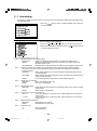
3. Functions
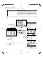
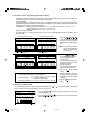
3 - 1 Specifications
Item
Specification
Source power requirement
Environmental condition
Dimensions
Weight
Input voltage
DC24V, 0.02A (Maximum loading)
Power received from PAC-SC50KUA Power Supply Unit via M-NET transmission
line, or from an R410A compatible CITY MULTI outdoor unit (except the S Series).
*Note: While the power to the connected outdoor unit is turned off, the
G-50A cannot perform a schedule operation, collect charge
data, or perform energy save control.
DC12V, 0.2A (Maximum loading)
Power is received from the PAC-SC50KUA Power Supply Unit via the DC power line.
Operating
0˚C ~ +40˚C / 32˚F ~ +104˚F
Non operating
– 20˚C ~ +60˚C / – 4˚F ~ +140˚F
Humidity
30 ~ 90%RH (No condensation)
mm 120 (H) × 300 (W) × 80 [*19] (D)
*[ ]: indicate the thickness from
in
4-3/4 (H) × 11-13/16 (W) × 3-1/8 [*3/4] (D) the wall.
kg
1.0
lb
2-1/4
Temperature
System condition
Number of control unit
User operating function
ON/OFF
Operation
mode
*1
Fan speed *1
Operation
Air direction
and swing
operation *1
Temperature
setting
Indoor unit or independent OA processing unit or LOSSNAY
: 50 units maximum (50 groups maximum)*3
Number of units (indoor or independent OA processing unit or LOSSNAY) in one group
: 1-16 units
*Note Indoor unit, independent OA processing unit and LOSSNAY can not register to the same group.
Number of remote controllers in one group
: 1-2
Number of system controllers in one group
: 0-4 (including the number of remote controller in one group)
: 0-3 for groups which have one remote controller.
Number of indoor units interlocked with one OA processing unit or LOSSNAY
: 0-16 (some types of OA processing unit can only be operated when interlocked to a maximum of 9 units)
The ON/OFF operation can be performed as a collective or per group.
The switch operation for the operation mode setting can be performed as a collective or
per group.
[Selectable operation mode for the indoor unit]
COOL/DRY/FAN/AUTO/HEAT
[Selectable operation mode for the independent ventilation]
HEAT RECOVERY/BY-PASS/AUTO
The switch operation to set the High and Low speed can be performed as a collective or
per group.
(The 4 fan speed setting is available to the indoor that has 4 levels)
(Fan speed is settable to AUTO on the indoor units that support that setting via G-50A of
ver. 3.10 or later.)
The air flow direction can be switched to 4 directions and swing operation as a collective or per group.
(Airflow setting can be switched to "5 directions" or to "AUTO" on the indoor units that
support those settings via G-50A of ver. 3.10 or later.)
Temperature setting can be performed collectively or per group.
[Setting temperature range]
Cool (Dry) operation : 19 ~ 30˚C / 67 ~ 87˚F
Heat operation
: 17 ~ 28˚C / 63 ~ 83˚F
Auto operation
: 19 ~ 28˚C / 67 ~ 83˚F
–4–
WT03945X02_En_P01-35
4
07.3.23, 8:12 PM
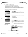
Item
Prohibit local
remote
control
Operation
Timer
operation
Filter sign
reset
Ventilation
operation *1
Monitor
Collective
operation
Each group
operation
Operation
mode
Fan speed
Air direction
Temperature
setting
Timer
operation
Filter sign
Local remote
control
prohibition
Ventilation
operation
Room
temperature
display
Central control
prohibition
External
input signal
condition
Malfunction
Current time
back-up
Other
Timer setting
Specification
The specific functions of a local remote controller can be prohibited as a collective or
per group.
[Prohibit function]
ON/OFF operation, Operation mode setting, Temperature setting and Filter sign
reset operation.
The set schedule operations can be switched to ON/OFF (local remote controller operation prohibition/permission) for each group.
The filter sign reset operation after the air filters are cleaned can be performed as a
collective or per group.
The ventilation operation of the interlocked OA processing unit or LOSSNAY can be
collective or per group.
[Ventilation operation]
Low speed/High speed/Ventilation OFF
The overall status lamp displays conditions of the collective statues.
Each group operation is displayed on the operation setting screen (group) or operation monitor screen.
Displayed on the operation setting screen (group).
The unit address and error code are displayed on the malfunction monitor screen
when a malfunction occurs.
When the power is cut off, the current time is backed up for approximately one week.
(When the controller is fully charged. The controller is fully charged by twenty-four
hours after power feed.)
Operation pattern setting can be performed.
• Operation interval: Minimum 10 minutes
• The daily operation pattern and weekly schedule for each group can be set.
• A pattern of one day: P1/P2/P3/
/
/
/
/* ON/OFF setting up to three times a day are possible for P1/P2/P3.
*
enables to set operation prohibition of 3 times per day for the remote controller.
*
/
/
implement the schedule which has combined P1/P2/P3 of ON/OFF
pattern and
of remote controller operation prohibition pattern together.
(
= P1 +
/
= P2 +
/
= P3 +
is displayed.)
* - is a day without timer operation.
• "The reference temperature and set-back value" or "Setting temperature" which are
linked with timer operation can be set.
–5–
WT03945X02_En_P01-35
5
07.3.23, 8:12 PM
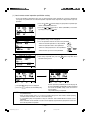
Item
Specification
Group name
Group name can be specified and display on the operation setting screen.
designation
* Group name setting is need at the initial setting.
External
Emergency stop/normal, ON/OFF, prohibit/permit for local remote operation can be consignal input
trolled for units being controlled with a non-voltage contact signal input from an external
Other
interface
source.
External
When one or more units being controlled are operating, the "ON" signal will be output,
signal output
and if a malfunction occurs in one or more units, the "malfunction" signal will be output.
interface
Initial setting (for installation and maintenance)
The group setting operation for units (indoor units local remote controllers, independent
Connecting Group setting OA processing unit, LOSSNAY and sub system controllers) are performed on the group
information
setting screen.
setting
Interlocked
The interlocked setting for the ventilation equipment as the OA processing unit or
setting
LOSSNAY, etc to indoor unit is performed on the interlocked setting screen.
Malfunction
A maximum of the 64 most recent malfunction are displayed on the malfunction log
history
monitor.
Monitor
Refrigerant
system monitor The connected unit address are displayed on the refrigerant monitor screen.
Some of the indication and function that appear on the each screen can be specified to
User setting
match the needs of the user.
Main system
Main/Sub setting of the system controller.
controller/
Sub system
controller
* G-50A does not support sub controllers.
setting
*2
Other
Prohibition
setting enable The setting of a system controller which the local remote control is prohibition enable
or disable.
/disable
The prohibited
Selecting of the prohibited controller which is only local remote controller or both local
controller
range setting remote controller and the other system controller.
K-control
The system composed of K-control type air conditioner equipment can be controlled
type
using the K transmission converter (PAC-SC25KAA).
*1 Each operation is available in accordance with the function of unit.
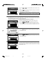
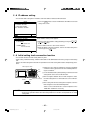
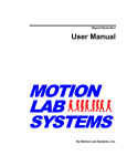
*2 Main system controller and sub system controller.
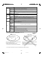
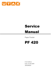
G-50A
management range
* G-50A does not
support sub
controllers.
M-NET Gateway
management range
Another system controller
management range
Management range
of G-50A
Unit
Unit
Unit
Unit
When G-50A controls another system controller or when
the system contains only G-50A:
G-50A is set as the main system controller.
* G-50A performs the group setting in this configuration.
When G-50A is controlled by another system controller:
(Example: MJ-300Gateway)
G-50A is set as the sub system controller.
* The group setting is performed by main system controller.
*3 The number of connectible units may be fewer depending on the indoor unit models.
–6–
WT03945X02_En_P01-35
6
07.3.23, 8:12 PM
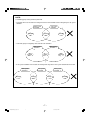
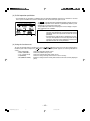
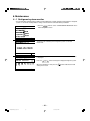
NOTE:
The following group setting cannot be performed.
• Unit groups which are not under the management of the main controller and are managed by the sub system
controller.
Main system
controller
Group
Sub system
controller
Group
Group
• A common group is managed by more than two main controllers.
Main system
controller 1
Group
Main system
controller 2
Group
Group
• A sub system controller which exceeds the management range of the main system controller of two or more.
Main system
controller 1
Group
Sub system
controller
Group
Main system
controller 2
Group
Group
–7–
WT03945X02_En_P01-35
7
07.3.23, 8:12 PM
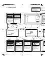
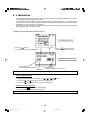
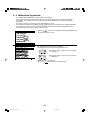
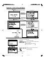
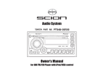
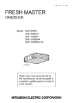
3 - 2 Display Screen
Operation setting function
Overall status lamp
The lamp indicates the unit operation condition.
ON......During operation
OFF......All group are stopping
BLINKING......Malfunction
Operation monitor function
Display
02
01
PROHI
BITED
Each operation and monitor of unit is
performed in collective or group unit.
Refer to section "4. User operation
(page 10)" for the detail of operation
methods.
ON/OFF operation and monitor of unit
are performed. Refer to section "4.
User operation (page 10)" for the
detail of operation methods.
G-50A
NOTE: The temperature setting
includes a function to switch the
display between Celsius (˚C) or
Fahrenheit (˚F) (page 34).
User operation function
2
1
Initial setting menu (Installation/Maintenance)
User operation menu
Continuously press
and
(2 seconds or longer)
1 OPERATION MONITOR
1 GROUP SETTING
2 OPERATION SETTING
3 SCHEDULE SETTING
4 MALFUNCTION
MONITOR
5 CURRENT TIME
SETTING
6A
ENTER
2 INTERLOCKED
SETTING
3 REFRIGERANT
MONITOR
4 MALFUNCTION
MONITOR
5 USER SETTING
7F
8 IP
NEXT
3
1
4
Timer setting function
BACK
5
Malfunction monitor function
2
Current time setting
04-2002 MON
Group setting function
001
( D AY - M O NT H -Y E A R )
P4
The weekly schedule setting is
performed in group units.
Refer to section "4-3 Timer
operation (page 19)" for the
detail of operation methods.
Function when the timer operates
The unit address, error code
and the unit address which
detected the malfunction are
displayed when a malfunction
occurs.
Refer to section "4-4 Malfunction (page 23)"
Function when the unit malfunction
The current time setting can be
performed.
Refer to section "4-5 Current
time setting (page 24)" for the
detail of operation methods.
Function when the current time
–8–
WT03945X02_En_P01-35
8
07.3.23, 8:12 PM
This performs the same group
setting of the indoor unit, local
remote controller and sub
system controller, etc.
Refer to section "5. Initial
setting (page 25)" for detail of
operations.
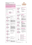
Collective operation switch
If this switch is pressed during the
operation, a whole group stop is
performed.
The collective operation switch can be performed in the user setting mode for any screen.
(Excluding menu screen)
LAN changeover switch
Refer to section "5. Initial setting (page 25)" for
explanation of the operation of these switches.
LCD contrast adjustment knob
LAN status lamp
Orange LED indicates action and green LED indicates link.
Service LAN connector
Refer to section "5. Initial setting" for an explanation of this connector.
Rear side
Ethernet
M-NET
A
B
POWER
S
12VDC GND
1 CN1 5
RS232C
1
CN2
9
G-50A
Operation
panel
M-NET Transmission
line terminal
LAN (Ethernet) connector
RS-232C connector
External input/output interface connector
Refer to section "7. External input/output
function (page 38)" for the detail of operation of these connectors.
DC power supply terminator
M-NET address setting
Function select setting
IP address setting
6
FUNCTION SETTING
ADDRESS SETTING
7
6 ADDRESS SETTING
ENTER
IP ADDRESS SETTING
1 2 3 4 5 6 7 8
M-NET ADDRESS: 000
IP ADDRESS:
192.168.001.001
SUBNET MASK:
255.255.255.000
ON
OFF
8
7 FUNCTION SETTING
8 IP ADDRESS SETTING
Display, or sets, the controller MNET address.
Refer to section "5. Initial setting
(page 25)" for a detailed explanation of operation.
VER.
Sets the function of the controller.
Refer to section "5. Initial setting
(page 25)" for a detailed explanation of operation.
Sets the LAN IP address.
Refer to section "5. Initial setting
(page 25)" for a detailed explanation of operation.
.
Required function for initial settings
BACK
3
4
5
2
Interlocked setting function
User setting function
Refrigerant monitor function
GROUP NO
Malfunction log monitor
2002
16-04-2002
014 6602
NONE
12 : 45
(DETECT 014)
2002
INDICATE
05-04-2002
012 6607
INDICATE
1-1-2001
7
This function sets either single or
multiple indoor units, the
LOSSNAY or any other OA
processing unit that interlocking
operates, as units in the same
operation.
Refer to section "5. Initial settings
(page 25)" for detail of operations.
NONE
TEMP. UNIT ˚C / ˚F
The function selections of the display method and timer settings that
is displayed on the screen.
Refer to section "5. Initial settings
(page 25)" for detail of operation.
The unit addresses are displayed
for each refrigerant.
Refer to section "6. Maintenance
(page 36)" for detail of operation.
Required function for initial settings
9
A malfunction logging which can
store a maximum of 64 items that
can be monitored.
Refer to section "6. Maintenance
(page 36)" for detail of operation.
Start-up and maintenance functions
–9–
WT03945X02_En_P01-35
09 : 12
(DETECT 012)
2002
07.3.23, 8:12 PM
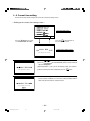
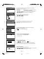
4. User operation
Used the following two screens when user operation is performed.
Operation monitor screen ........ This screen displays ON/OFF and malfunction condition of unit.
G-50A normally displays this screen.
Operation setting screen .......... The unit operations can be performed by individual group or collective operation. These operation include the ON/OFF, operation mode, fan speed,
temperature setting, air direction, ventilation setting, timer operation ON/OFF,
local remote controller prohibition and filter sign reset are performed by group
or collectively. In addition, this screen can also displays the room temperature of each group.
• The collective operation can be performed on any screen (except for the menu screen) in the user operation mode.
<Shifting to the operation monitor screen and operation setting screen>
User operation menu screen
Press the 2
switch and
select "2 OPERATION SETTING"
Press the 1
switch and
select "1 OPERATION MONITOR"
Press the
BACK
SCREEN
switch.
Operation setting screen
Operation monitor screen
Press the
Press the
ENTER
switch.
or
switch to set
"MON. (MONITOR)" on the blinking display and press the
ENTER
switch.
The unit operation can be verified in
a single glance.
Press the
or
switch
to set "COL.(COLLECTIVE)" or
"GROUP" on the blinking display
and press the
ENTER
(Individual group
operation setting
screen)
switch.
Refer to section "4-1 Operation
condition monitor".
<Returning to the user operation menu screen>
Press the
BACK
SCREEN
(back screen) switch.
Each unit operation
setting is performed.
(Collective
operation
setting screen)
Refer to section "4-2 Operation setting".
– 10 –
WT03945X02_En_P01-35
10
07.3.23, 8:12 PM
4 - 1 Operation condition monitor
• This function displays the ON/OFF/Malfunction status of specific units or group.
• ON/OFF/Malfunction status is shown by the indication corresponding to the unit or group appearing in inverse,
normal or blinking display.
• The user may select display items by unit address, group number or group name.
Refer to section "5-7 User setting (page 34)" for detail of user setting.
• During the user operation mode, this screen returns from any screen if there is no operation for approximately 10
minutes.
(1) Operation Method
• Note that operation is different for each of the following display methods.
<Unit address display>
GROUP
1 Press the
SELECT
eration and monitor.
switch to change the display group in desired op-
2 When displaying the units in a given group, press the
all the units in that group ON or OFF.
ON/OFF
1
switch turn
<Group number display>
1 Press the
switch to move the " " select the group
number to be operated.
ON/OFF
switch to set the displayed group unit is indicated by the
2 Press the 1
" " symbol to the on/off mode.
<Group name display>
1 Press the
switch to move the " " symbol. Select
the group name to be operated.
ON/OFF
2 Press the
switch to set the displayed group unit is indicated by the
" " symbol to the on/off mode.
1
*Displays up to the first 3 characters of the set group name.
(2) Display contents
Reverse: ON
Normal: OFF
Blinking: Malfunction during
units is off.
Blinking and Reverse:
Malfunction during
unit is on.
OR
*When a malfunction occurs, refer to section "4-4 Malfunction (page 23)".
– 11 –
WT03945X02_En_P01-35
11
07.3.23, 8:12 PM
4 - 2 Operation setting
• There are two methods for the operation, performing the operation classified by groups or collective operation.
4 - 2 - 1 Group operation setting
Display
Room temperature display*1
Group number display
Operation mode
display
Operation
condition display
Fan speed display
Air direction display
Set temperature
display
Ventilation operation
display
Remote operation
prohibition/permission
display
Filter sign display
External input
condition display
Timer operation
display
Function area
No. Name of switches
Function
Display
Operation status display
1 ON/OFF switch
The ON/OFF condition of the displayed
group is switched.
Used to the type of the operation mode
selection.
2
Operation mode
switch
Note:
Operation mode can be selected according to the function of unit.
If the unit is only cooling type
HEAT/AUTO mode may not appear
on the display.
Refer to the instruction manual of the
air conditioner for more detail.
* When there is an interlocked OA processing unit or
LOSSNAY, turning this switch ON starts operation
in a [High] ventilated state.
Each time to push the switch, a mode is selected in a
sequence that goes from COOL, DRY, FAN, AUTO,
HEAT and beck to AUTO for air conditioner group.
On the group composed of independent LOSSNAY,
operation mode is selected in a sequence that goes
from HEAT RECOVERY, AUTO, BY-PASS and back
to HEAT RECOVERY.
Fan speed display
* Indicates AUTO (On the version 3.10 or later, this symbol
appears if the AUTO function is available on the indoor unit.)
3
Fan speed
switch
The fan speed can be switched to four
levels. Switching may be 3 levels or 2
levels, depending on the model.
4 levels
2 levels
4 Temperature
setting switch
The setting temperature change is performed.
3 levels
The setting temperature display.
The setting range change according to the operation
mode. (1°C unit/2°F unit)
COOL/DRY
19 ~ 30˚C / 67 ~ 87˚F
HEAT
17 ~ 28˚C / 63 ~ 83˚F
AUTO
19 ~ 28˚C / 67 ~ 83˚F
NOTE: The temperature setting includes a function
to switch the display between Celsius (°C) or
Fahrenheit (°F) (page 34).
– 12 –
WT03945X02_En_P01-35
12
07.3.23, 8:12 PM
Operation panel
2 Operation mode
switch
A Group select
switch
3 Fan speed
switch
1 ON/OFF switch
6 Air direction
setting switch
4 Temperature
setting switch
B Back screen
switch
5 Current time
setting switch
C Cursor position
movement switch
8 Remote operation
prohibit switch
9 Timer mode
switch
7 Ventilation
setting switch
No. Name of switches
Function
Current time
These switches are used when the cur5
setting switch
rent time is set.
0 Reset switch
Display
Refer to section "4-5 Current time setting".
Air flow direction
6 Air direction
setting switch
7
Ventilation setting switch
Remote
8 operation
prohibit switch
9
Timer mode
switch
0 Reset switch
Group select
A
switch
Back screen
switch
Cursor position
C
switch
B
The Air flow direction can be selected.
The air flow direction can be selected to
four directions and swing operation (auto
vane).
The operation mode of the interlocked
ventilation can be performed.
*Where there is no interlocked ventilation,
the operation of this switch is invalid.
* "Ventilation" is OA processing unit or LOSSNAY.
Used to prohibit for the local remote
control.
The timer operation can be performed
according to a previously set operation
pattern.
The filter sign display reset is performed. The reset processing is
completed by pressing this switch two
times.
* On the version 3.10 or later, these airflow direction
icons appear if the corresponding functions are available on the indoor unit.
Ventilation volume setting display
PROHIBIT: Local remote control specified on the
prohibit setting screen is not possible.
PERMIT: Local remote control is possible.
Timer operation display
ON
OFF
Filter display
[ Filter ]
No display
The display group is changed.
Group number display
This switch displays 1 ~ 50 group numbers.
The switch can also display group names.
Use to back to the user menu screen.
The menu screen will be returned.
The position of a cursor can be moved
when a cursor is appear.
The cursor position (blinking) moves.
*1: Room temperature can be displayed by selecting the room temperature display function per "5-7 User Setting"
(but limited to indoor unit group).
– 13 –
WT03945X02_En_P01-35
13
07.3.23, 8:12 PM
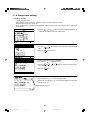
(1) Local remote control operation prohibition setting
• G-50A can prohibit the operation of item such as connected local remote controller or sub system controller for
each group. The prohibit items are ON/OFF operation, operation mode, temperature setting and filter sign reset
operation.
GROUP
switch to display the group that the operation pro1 Press the
SELECT
hibition setting will be performed.
2 Press the
or
switch to set "PROH. (PROHIBIT)" on the blinking display and press
switch.
ENTER
1 The prohibit setting screen is displayed.
2 Press the operation switch for the items to be prohibited.
ON/OFF
• When the ON/OFF operation is to be prohibited
:
1
• When the operation mode is to be prohibited
:
2
• When the setting temperature is to be prohibited
:
4
MODE
• When the filter sign reset is to be prohibited
:
or
7
RESET
DEL.
1 The items selected for prohibition are shown in reverse display.
2 After setting of prohibit item, press the
operation setting screen.
2 Press the
NOTE:
0
switch to set "PROHIBIT [ON]".
• The system controller that performed the local remote control operation prohibition setting can operate
the prohibited items.
• When the No.4 function select is set ON, the prohibit setting of the local remote control operating
cannot be made. For details, refer to "5-3 Function setting".
• In a LOSSNAY group, the operations of only the "ON/OFF" and "FILTER RESET" functions can be
prohibited.
• When an M-NET remote controller is used, it must be properly registered to the group for the G-50A unit
to be able to prohibit its operation.
– 14 –
WT03945X02_En_P01-35
switch to go back to the
Remote operation prohibition/permission display will
be change [PERMIT] to [PROHIBIT] and the prohibited
item set on the prohibit setting screen are shown in
reverse display.
The prohibit setting is completed.
1 The operation setting screen is displayed.
REMOTE
PROHIBITION
BACK
SCREEN
14
07.3.23, 8:12 PM
(2) G-50A operation prohibition
• The operation of this controller is prohibited when an operation prohibition setting for this controller is received
from a system controller other than this controller or when an external input signal is used.
PROHI-
The BITED is displayed and the prohibition operation is display in reverse
display when operation of this controller is prohibited by another system
controller or an external input signal used.
The prohibition operation which is displayed in reverse display is not possible to operate in this condition.
NOTE:
• If the Level Run/Stop function is controlled via an external input, local operation of the Run/Stop button will be
prohibited, and the timer operation function will also be
prohibited.
• If the Emergency Stop function is controlled via an external input, local operation of the Run/Stop button during
emergency stop status will be prohibited, and the timer
operation function will also be prohibited.
(3) Using the function area
To select the function from the function area, use the
or
switch to move the cursor to the blinking to the
function of your choice and press the
switch. The current cursor position appears as a blinking indication on
screen.
• MON. (MONITOR)
: Shift to the operation monitor screen.
• PROH. (PROHIBIT)
: Shift to the prohibit setting screen.
• COL. (COLLECTIVE)
: Shift to the collective operation setting screen.
• M (MEMORY)
: Stores the setting currently shown on the screen in memory.
• MR (MEMORY READ)
: Reads the setting stored in memory and activates them for the currently displayed
group.
ENTER
– 15 –
WT03945X02_En_P01-35
15
07.3.23, 8:13 PM
4 - 2 - 2 Collective operation setting
• A collective operation setting and a collective prohibit setting can be performed for all the group managed by this
controller at one time.
(1) Collective operation setting
1 Press the
switch to set "COL. (COLLECTIVE)" in blinking
display and press the
switch on the group operation setting screen.
ENTER
2 The collective operation setting initial screen is displayed.
3 Select the items for operation setting on the collective operation setting
initial screen.
The operation method is same as described in section "4-2-1 Group
operation setting" (Page 12).
NOTE: The items which were not set, remain set to the same condition that were set before the collective operation was performed.
4 The items selected for the operation blink on the collective operation
setting screen.
5 When all setting are completed, press the
switch to display
the "SET" in blinking display for the indicated function area.
6 Press the
ENTER
switch one time to complete this setting.
The collective setting is completed when the previous items light. (After the setting are completed,
start from step 3 to perform operation again if
change operation are required.)
The collective setting is executed.
The collective setting takes approximately 20
seconds.
NOTE: The display of setting contents is erased
when shift to another screen.
– 16 –
WT03945X02_En_P01-35
16
07.3.23, 8:13 PM
(2) Collective prohibit setting
1 Press the
play and press the
screen.
switch to set "PROH. (PROHIBIT)" in blinking disswitch on the collective operation setting initial
ENTER
2 The collective prohibit setting initial screen is displayed.
3 Select the items to be prohibited or permitted on the collective prohibit
setting initial screen.
Each time to press the switch corresponding to the prohibition item, the
prohibition or permission is selected.
Prohibition setting: The prohibited item is displayed in reverse with
blinking.
Permission setting: The permitted item is displayed with blinking.
The selection method concerning to prohibit/permit item is same as described in section "4-2-1 (1) Local remote control operation prohibit setting" (page 14).
4 The items selected for the prohibition or permission are displayed with
blinking.
And the "SET" is displayed with blinking in the function area.
5 When all setting are completed, press the
plete this settings.
6 The collective prohibit setting is excused.
The collective prohibit setting takes approximately
20 seconds.
8 After setting of prohibit/permit items, press the
switch to back to the collective operation setting initial screen.
– 17 –
17
switch one time to com-
7 The collective setting prohibition/permission item
setting is completed when the previous item light.
BACK
SCREEN
WT03945X02_En_P01-35
ENTER
07.3.23, 8:13 PM
9 The collective operation setting initial screen is displayed.
0 Press the
REMOTE
PROHIBITION
0
switch to set "REMOTE CONTROL [PROHIBIT]".
ARemote operation prohibition/permission display ("REMOTE CONTROL
[PROHIBIT]") is displayed with blinking.
BPress the
or
switch to display the "SET" in blinking display for
the indicated function area.
Press the
switch one time to complete the collective prohibit setting.
ENTER
C The collective prohibit setting is executed.
It takes approximately 20 seconds.
D The collective prohibit setting is completed when the remote operation
prohibition/permission display is change to be light.
NOTE: • The display of setting contents is erased when shift to another screen.
• The following restrictions in the collective operation settings.
1. Temperature setting
The range that can be set falls within 19˚C ~ 28˚C /67˚F ~ 83˚F regardless of the operation mode.
2. Operation mode selection, fan speed selection, air direction, etc., can be collectively set regardless
of the functions of the unit. However, actual setting to a unit without functions cannot be performed.
To obtain the correct setting contents, refer to the respective group operation setting screens.
• When an M-NET remote controller is used, it must be properly registered to the group for the G-50A
unit to be able to prohibit its operation.
– 18 –
WT03945X02_En_P01-35
18
07.3.23, 8:13 PM
4 - 3 Timer operation
• A weekly schedule setting can be specified for each group.
• Possible to set on the timer the schedule to prohibit operation of the local remote controller in addition to ON/OFF
schedule.
NOTE: • Always set to current time on the current time setting screen when the schedule setting is performed.
Refer to section "4-5 Current time setting".
• To perform a scheduled operation, make the settings that are explained under items (1) (p.20), (2)
and (3) (p.21), and set the Timer mode switch on the OPERATION SETTINGS screen to ON.
Refer to section "4-2 Operation setting".
• When browser monitoring, or schedule setting from central monitoring PC, was performed, the timer
screen of this function cannot be used.
• When the "Annual/Weekly Schedule" is used, the "Timer" menu will not appear on the menu screen.
• When an external input signal that corresponds to "Emergency Stop" or "Level Run/Stop" is being
input, timer operation will not be performed.
<Schedule setting function summary>
1 The ON and OFF (PROHIBITION and PERMISSION) times can set in 10-minute units.
2 The daily operation schedule can include up to three ON (PROHIBITION) time settings and three OFF
(PERMISSION) time settings.
3 Three types (P1-P3) of daily ON/OFF pattern and one type (P4) of prohibition/permission pattern* are available
respectively, each of which can be set every to each group.
* "Prohibition/Permission" setting can only be made collectively for all applicable items; it cannot be set individually for each item.
Week day which is not set in timer pattern is displayed with (-).
In addition, it is also possible to set the schedule which has combined P1-P3 and P4 together.
(
/
/
) In this case, both of ON/OFF pattern and prohibition/permission pattern are daily executed.
Any one of these options may be selected for each separate day of the week.
4 The schedule patterns can be copied easy to other group by the memory and memory read functions because
the schedule contents can be recorded in the memory.
5 The setting temperature or set-back value setting can also be supported during timer operation.
<Shifting to the schedule setting screen>
User operation menu
BACK
SCREEN
Press the
switch to go back to the
user operation menu screen.
Press the 3
switch to select
"3 SCHEDULE SETTING".
Weekly schedule setting screen
• The schedule contents of each group
can be monitor.
• Weekly schedule pattern setting can
be performed.
Press the
switch to move the cursor position
to P1 (or P2 or P3 or
).
(The "P1" indication blinking.)
switch to the
And press the
P1 (Pattern 1) Schedule pattern
setting screen.
Press the
BACK
SCREEN
switch.
ENTER
Schedule pattern setting screen
• Schedule pattern (P1~P3,
can be performed.
– 19 –
WT03945X02_En_P01-35
19
07.3.23, 8:13 PM
) setting
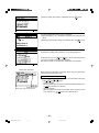
(1) Schedule pattern (P1~P3) setting
• Follow the procedures described below to set each daily schedule pattern for each group.
• The setting temperature or set-back values setting are also performed in the schedule setting operation. To enter
the setting temperature or set-back value setting select SET-BACK or SET TEMP. Accordance with section "5-7
User setting (page 34)" in advance.
• The setting temperature or set-back value selected in this way take effect only during timer operation. Also
setback operation is cancelled if the setting temperature is changed using this central controller or a local remote
controller.
(The set-back operation resumes at the next timer-ON time)
<Schedule pattern setting (P1 ~ P3,
)>
1 Press the
ting.
GROUP
SELECT
2 Press the
the pattern (P1 ~ P3,
3 Press the
ENTER
switch to display the group in desired a timer setswitch to move the cursor position to
) to be setting.
switch one time.
4 The schedule pattern setting screen is displayed.
switch to move the cursor position to
5 Press the
the first ON (PROHIBITION) time.
CLOCK / PATTERN
6 Press the 5
switch to select the ON (PROHIBITION) time.
/ 8
(Time is changed by 10 minutes unit.)
7 Press the
ENTER
switch one time to set ON (PROHIBITION) schedule.
(The cursor moves to the next setting position.)
8 Perform operation 6 to select OFF (PERMISSION) time.
9 Perform operation 7 to set the OFF (PERMISSION) time.
0 Repeat operation 6 to 9 to set the second and third ON/OFF
(PROHIBITION/PERMISSION) schedules in the same manner.
When the second or third ON/OFF (PROHIBITION/PERMISSION)
schedule is not used, the characters "– –:– –" remain display and press
switch one time.
the
ENTER
A To cancel the ON/OFF (PROHIBITION/PERMISSION) time that was set
previously, use the
switch to move the cursor to
DEL. switch.
the time position to be cancelled and press the
RESET
B When the P1 setting are completed, perform operation 2 to A as
necessary to perform the setting for P2 or P3 or
.
NOTE: • To disable a function beyond the date line, set the "Disable Start Time" to "00:00".
Also, item
must be enabled for both dates.
– 20 –
WT03945X02_En_P01-35
20
07.3.23, 8:13 PM
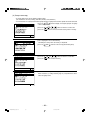
(2) Set-back values and setting temperature setting
• Setting the set-back values and setting temperature can be performed only when selecting either "SET BACK" or
"SET TEMP" on the user setting screen in the initial setting mode.
• Set-back operation
Set-back operation is a method which reduces the air conditioner running cost by controlling the operation with
specified time band for lowered load. In other words the unit operates at a few degrees higher for cooling and a few
degrees lower for heating in the specified time band.
<<EXAMPLE>> When the reference temperature is 24˚C / 75˚F and the set-back value is set to 2˚C / 4˚F.
• Cooling operation: 24˚C+2˚C=26˚C / 75˚F+4˚F=79˚F
• Heating operation: 24˚C-2˚C=22˚C / 75˚F-4˚F=71˚F
• Setting temperature operation
This operation sets the temperature when timer ON is set to a predesignated temperature regardless of the
operation mode.
<Set-back operation selected>
<Setting temperature selected>
1 Press the
switch to move the cursor position to the set-back reference
temperature or setting temperature.
Set-back value
Reference temperature
NOTE: The temperature display
can be switched between
Celsius (°C) or Fahrenheit
(°F) (page 34).
Setting temperature
/ 8
2 Press the 5
(CLOCK/PATTERN) switch to
select the following items.
• Set-back value;
The reference temperature and
set-back value for each ON time
period are selected.
• Setting temperature:
The setting temperature for each
ON time period is selected.
3 Press the
setting.
* The selecting range:
• The reference temperature for set-back operation
: 19˚C ~ 28˚C (1˚C unit) / 67˚F ~ 83˚F (2˚F unit)
• The set-back value
: 0 ~ 9 degree (1 degree unit)
/ 0 ~ 18 degree (2 degree unit)
• The setting temperature : 19˚C ~ 28˚C (1˚C unit) / 67˚F ~ 83˚F (2˚F unit)
ENTER
switch to make
4 Repeat operations 2 and 3 to
set the set-back value or setting
temperature for each ON/OFF
schedule.
5 Press the
ished.
BACK
SCREEN
switch, when fin-
(3) Weekly schedule setting
The schedule pattern P1 to P3, local remote control prohibition (P4),
P1 to P3 and P4, and non-timer operation (-) are set for each day.
GROUP
1 Press the
SELECT
schedule setting.
2 Press the
position to be set.
to
of a composite pattern composed of
switch to display the group in desired weekly
switch to move the cursor to the pattern
– 21 –
WT03945X02_En_P01-35
21
07.3.23, 8:13 PM
3 Press the
or (-).
/
5
8
(CLOCK/PATTERN) switch to select P1 to P4
switch one time to complete the setting. (The cursor will
4 Press the
move to the next setting position.)
ENTER
5 Repeat operations 3 and 4 to assign the schedule pattern to each day.
NOTE: When the No.4 function setting is set ON, P4 cannot be set.
(4) Copying schedule content to other groups (memory, memory read)
• The schedule pattern P1 to P3, weekly schedule pattern, set-back value or setting temperature of one group can
be recorded and copied to memory or to another desired group.
• Correction and modification can be easily performed after the copy operation is completed.
1 Display the original group on the weekly schedule setting screen.
2 Press the
switch to move the cursor to "M".
switch one time to record the setting date in memory.
3 Press the
*To erase date from the memory, return to the user operation menu screen.
ENTER
4 "M" is displayed in reverse with blinking.
5 Press the
be copied.
GROUP
SELECT
6 Press the
switch to select the group to which the data is to
switch to move the cursor to "MR".
7 Press the
switch to set the contents which will be the same as the
setting data in memory.
ENTER
The same contents are displayed.
The contents stored in memory can be copied to other groups any number
of times because these contents will not be erased even if the memory
read operation is used.
– 22 –
WT03945X02_En_P01-35
22
07.3.23, 8:13 PM
4 - 4 Malfunction
• The malfunction monitor function is used for conforming to the details of the malfunction condition when a malfunction is displayed on the operation monitor screen.
• The malfunction monitor function can display data describing up to nine malfunctions in the address number
sequence on one page. This data contains the unit address where the malfunction occurred, the error code and the
unit address where the malfunction was detected.
• After checking the unit address where the malfunction occurred and the error code, please contact your dealer or
technical representative as soon as possible.
< Shifting to the malfunction monitor screen >
User operation menu
Press the 4
switch to
select "4 MALFUNCTION LOG MONITOR".
BACK
SCREEN
Press the
switch to go back
to the user operation menu screen.
Malfunction monitor screen
The unit address
where the malfunction occurred
The unit address
where the malfunction was detected
Error code
NOTE: When there is no malfunction taking place, [NO ERROR] lights up instead of [ERROR CODE].
Page change operation
The page change operation is performed by the
switch.
Pressing the
or
switch shows the current display page +1.
Pressing the
or
switch shows the current display page -1.
Malfunction reset operation
RESET
DEL. switch to reset all malfunctions.
Press the reset
The reset operation can be performed on any page.
NOTE: When operation of the G-50A is prohibited, reset operation is invalid.
– 23 –
WT03945X02_En_P01-35
23
07.3.23, 8:13 PM
4 - 5 Current time setting
The current time, day, month and year are set on the current time setting screen.
< Shifting to the current time setting screen >
User operation menu
BACK
SCREEN
Press the 5
switch to select
"5 CURRENT TIME SETTING".
Press the
switch to back to
the user operation menu.
04-2002 MON
Current time setting screen
(DAY-MONTH-YEAR)
1Press the
8
2Press the 5
day that is displayed.
-2002 MON
(DAY-MONTH-YEAR)
switch to move the cursor position to be set.
(CLOCK/PATTERN) switch to set the number or
3Repeat operations 1 and 2 to set the date day, month, year and time.
4 Where all setting have been completed, press the
ENTER
switch.
5The current time setting is executed and "done" is displayed with blinking
for two seconds to indicate the current time setting completed and the
clock count will start with the second reset to 0.
2002 SUN
(DAY-MONTH-YEAR)
– 24 –
WT03945X02_En_P01-35
24
07.3.23, 8:13 PM
5. Initial setting
5 - 1 Shifting to initial setting menu
• Shift to the initial setting menu by continuously pressing
+
(2 seconds or longer) on the user operation
menu screen. (Refer to section "3-2".)
Shift to the user operation menu by continuously pressing
+
(2 seconds or longer) on the initial setting
screen. (Refer to section "3-2".)
• When group information is not saved, the following initial setting screen is displayed when power is turned on at
this controller.
MENU
WED 15:29
1
2
3
4
ADDRESS SETTING
FUNCTION SETTING
IP ADDRESS SETTING
GROUP SETTING
PLEASE SET
INITIAL SETTING
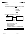
5 - 2 M-NET address setting
(1) Select 6
"6 ADDRESS SETTING" (or 1
"1 ADDRESS SETTING").
(2) Set the controller address by pressing the 0
to 9 INS. switches (000,201 ~ 250).
(3) When the
switch is pressed after setting, the screen returns.
BACK
SCREEN
MENU
WED 15:29
switch
Press the 6
to select "6 ADDRESS
ADDRESS SETTING
SETTING"
M-NET ADDRESS: 000
6 ADDRESS SETTING
7 FUNCTION SETTING
8 IP ADDRESS SETTING
BACK
SCREEN
Press the
switch to back
to the initial
setting menu.
• When the controller is shipped from the factory, the address is set to "000".
(Always set the address to "000" When the K transmission converter is managed.)
NOTE:
Observe the following precautions when this controller manages the M-NET models and K control
models by using the K transmission converter (PAC-SC25KAA).
Refer to the K transmission converter instruction manual for further details.
• Address of this controller
Always set the address of this controller to "000".
• Function select setting of this controller
Always set the No.3 function setting to ON.
• Indoor unit address
Set all the M-NET models of indoor units from 001, next, set the address of the K control indoor
unit.
Indoor unit address
001 ~ M-NET indoor unit maximum address < K control indoor unit
minimum address ~ 050
* Assign the address of the smallest K-control indoor unit in the group as the group number.
– 25 –
WT03945X02_En_P01-35
25
07.3.23, 8:13 PM
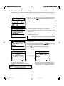
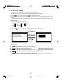
5 - 3 Function setting
• The functions of this controller are set according to the function settings.
• The functions selects are set to OFF when the controller is shipped from the factory.
(1) Select 7
"7 FUNCTION SETTING" (or 2
"2 FUNCTION SETTING").
(2) Switch the function by pressing the function No. you want to change, or the 1
to 8
switch of the same
number.
Each time the switch is pressed, the ON/OFF state of that No. is switched. (NO. 1 and NO. 2 cannot be changed.)
<Operation example>
1)When Input 3
switch was pressed.
3
3
ON
OFF
(3) When the
ON
OFF
BACK
SCREEN
: Active
switch is pressed at the end of function switching, the screen returns.
MENU
WED 15:29
Press the 7
switch
to select "7 FUNCTION
SETTING"
6 ADDRESS SETTING
7 FUNCTION SETTING
8 IP ADDRESS SETTING
FUNCTION SETTING
1 2 3 4 5 6 7 8
ON
OFF
BACK
SCREEN
Press the
switch to go back
to the initial
setting menu.
BACK
<Function selects>
Reserved for future use (Leave this switch set to OFF)
No. 1
No. 2
Reserved for future use (Leave this switch set to OFF)
No. 3
OFF: No K transmission converter installed
ON: K transmission converter installed
No. 4
OFF: Operation prohibit setting valid
ON: Operation prohibit setting invalid
No. 5
OFF: Emergency stop broadcast enabled (Be sure to use)
ON: Emergency stop broadcast disabled
No. 6
External input changeover (refer to section "7. External input/output function")
No. 7
No. 8
The range of a controller which the operation is prohibited
OFF: Both of the system controller and the local remote controller ON: Only the local remote controller
– 26 –
WT03945X02_En_P01-35
26
07.3.23, 8:13 PM
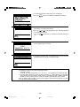
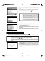
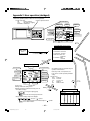
5 - 4 Group configuration setting
• Registration can be made for the indoor units, local remote controllers and sub system controllers in the same
group.
• Registration can be also performed for the group which is composed of only OA processing unit or LOSSNAY.
(Independent ventilation group)
<Example for the group configuration>
051
005
001
002
101
GROUP 1
Air conditioner group
003
006
004
Outdoor unit
Indoor unit
M-NET local remote controller
102
GROUP 2
GROUP 3
Independent ventilation group
OA processing unit or LOSSNAY
M- NET
Transmission line
• Supply the power from the power supply unit (PAC-SC50KUA) through the M-NET transmission line and DC line.
• Perform the following procedures to set the group configuration because the interlocked operation setting will not
be performed if the group configuration settings have not been performed.
WED 15:29
1
2
3
4
ADDRESS SETTING
FUNCTION SETTING
IP ADDRESS SETTING
GROUP SETTING
1When the power is supplied to the controller, the screen shown on the
left is displayed.
2Press the 1
(or 4
) switch to select "1 GROUP SETTING"
(or "4 GROUP SETTING").
PLEASE SET
INITIAL SETTING
The group configuration setting screen is displayed.
3Press the
GROUP
SELECT
switch to display the group number to be set.
4Press the
switch to move to move the cursor to
the address display position to be set.
5Used the numeric keypad switch to set the address of the indoor unit,
local remote controller, sub system controller in the display group number.
<Operation example>
When the indoor unit which address is 012.
1) Input "0"
0
2) Input "1"
01
3) Input "2"
012
4) Press the
switch 012
* It is also possible just enter "1" "2".
<When the input is incorrect>
Before pressing
switch, continue to input the data. After pressing
switch, move the cursor to the addresses to be deleted and press
DEL. switch to delete these addresses.
the
RESET
NOTE:
• Do not set interlocked ventilation unit such as OA processing unit or LOSSNAY.
• Even if the addresses are input any order, it is switched to a sequence starting with low-order
address.
• The independent ventilation unit can not set to the indoor unit group and it can not be set to as an
interlocked ventilation unit.
– 27 –
WT03945X02_En_P01-35
27
07.3.23, 8:13 PM
Set all the units and controllers to be registered in the displayed group
number.
6Repeat operation 3 to 5 to set all groups managed by this controller.
7When all setting are completed, press the
NOTE:
MENU
Additions
WED 15:29
switch.
• When there are M-NET local remote controllers in the
system, always be sure to set the local remote controller
address. The local remote controller will not operate if the
address setting is not performed.
However, when the local remote controller is an MA remote controller (PAR-20/21MAA) or K-control type remote
controller, setting is not performed.
• If there is a K transmission converter is a component in the
system, do not perform the group configurations setting of
this controller for the K transmission converter.
8The following initial setting screen is displayed.
When the interlocked operation settings are performed, refer to section
"5-5 Interlocked operation setting".
When the group name settings are performed, refer to section "5-6 Group
name setting".
When the user settings are performed, refer to section "5-7 User setting".
Group configuration date collective deletion
• Display "G00" in the group configuration setting screen and press the
delete the all group configuration data and all interlocked operation data.
NOTE:
BACK
SCREEN
DEL.
switch two times continuously to
• When this unit is set to the sub system controller by the function select, group registration can not be
made. However confirmation of the contents of group registration is possible.
• Simultaneously press the
and
keys on the user operation menu screen for 2 seconds to
perform group configuration setting. The initial setting menu screen is displayed. Select "1 GROUP
SETTING" on the setting menu screen, wait for the group setting screen to appear, and change the
setting.
9When the necessary initial settings are complete, simultaneously press
the
and
keys on the user operation menu screen for 2 seconds.
When returned to the user operation screen, register processing for the
group configuration information and initial set up processing for each unit
and each controller is executed. (This process takes approximately 5 ~
7 minutes.)
– 28 –
WT03945X02_En_P01-35
28
07.3.23, 8:13 PM
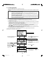
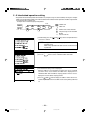
5 - 5 Interlocked operation setting
• Registration of interlocked operation of Ventilation unit (OA processing unit and LOSSNAY) with single or multiple
indoor unit is performed. All indoor units to be interlocked with ventilation unit for operation should be registered for
the interlocking with ventilation unit.
<Example for the interlocked group configuration>
Duct
051
001
002
101
003
004
Outdoor unit
005
Indoor unit
M-NET local remote controller
102
OA processing unit or LOSSNAY
M-NET
Transmission line
1Simultaneously press the
screen for 2 seconds.
and
keys on the user operation menu
NOTE: Always perform the mode change operation from the user
operation menu.
Mode change operation from other screens is ineffective even
if performed.
2Initial setting menu screen is displayed.
3Press the
2
switch to select "2 INTERLOCKED SETTING".
NEXT
4The interlocked setting screen is displayed.
Minimum address of the interlocked OA processing unit or LOSSNAY
unit which can be set to interlock with indoor unit is displayed on the
"INTERLOCKED UNIT ADDRESS" display position. And the cursor is
displayed in the unit address display position.
GROUP
5Press the
switch to display the address number of the interSELECT
locked OA processor unit or LOSSNAY that the setting will be performed
on.
– 29 –
WT03945X02_En_P01-35
29
07.3.23, 8:13 PM
6Used the numeric keypad switch to set the address of the indoor unit that
operates with displayed interlocked OA processing unit or LOSSNAY.
<Operation example>
When the indoor unit which address is 012.
1) Input "0"
0
2) Input "1"
01
3) Input "2"
012
4) Press the
switch 012
* It is also possible just enter "1" "2".
<When the input is incorrect>
Before pressing
switch, continue to input the data. After pressing
switch, move the cursor to the address to be deleted and press the
DEL. switch to delete these addresses.
7Set all the indoor units that operate with displayed interlocked OA processing unit or LOSSNAY.
8Repeat operation 5 to 7 to set the indoor units of all interlocked operation units managed by this controller.
9When all settings are completed, press the
BACK
SCREEN
switch.
Initial setting screen is displayed.
This ends the interlocked operation setting.
When the interlocked operation settings are performed, refer to section
"5-5 Interlocked operation setting".
When the group name settings are performed, refer to section "5-6 group
name setting".
NEXT
When the user setting are performed, refer to section "5-7 user setting".
and
keys on the initial setting menu
Simultaneously press the
screen for 2 seconds to complete user operation. After the initial setting
processing is completed (The initial setting screen will be displayed), refer
to section "4. User operation (page 10)" and perform user operation.
NOTE: When this unit is set to sub system controller by No.2 function select, interlocked operation settings
cannot be adjusted. However monitoring of the contents of the interlocked operation settings is possible.
– 30 –
WT03945X02_En_P01-35
30
07.3.23, 8:14 PM
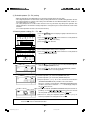
5 - 6 Group name setting
(1) Setting method
• Specify new group name.
• Either alphabet, numeric characters, hyphens or spaces can be used for name setting.
• Maximum of ten characters can be set.
• When the group name is displayed on the operation monitor screen, the first three characters of the group name
are displayed.
1Press the 1
(or 4
) switch to select "1 GROUP SETTING" (or
"4 GROUP SETTING") of the initial setting menu.
2The group configuration setting screen is displayed.
3Press the
switch to move the cursor to the "GROUP NAME
SET".
4Press the
ENTER
switch one time.
The group name setting screen is displayed.
5The character "
" is displayed in reverse.
6Press the
sired character.
7Press the
ENTER
switch to move the cursor to the deswitch.
The selected character is displayed in the group name display area.
8Repeat operation 6 or 7 and set the group name.
When incorrect character is set, refer to section "Group name correction
method (page 32)".
Group name display area
– 31 –
WT03945X02_En_P01-35
31
07.3.23, 8:14 PM
9When the group name setting is completed, press the
BACK
SCREEN
switch.
The group configuration setting screen is displayed.
0Repeat operation 3 to 9 and perform the group name setting for each
group.
AWhen all the group name settings are complete, press the
BACK
SCREEN
switch.
BThe initial setting menu screen is displayed.
To perform the setting, refer to section "5-7 User setting (page 34)".
Simultaneously press the
and
keys on the initial setting menu
screen for 2 seconds to complete user operation.
Next refer to section "4 User operation" and perform user operation.
NEXT
<Group name correction>
When performing corrections to the group name, move the group name
cursor to the character to be correct.
Group name cursor movement method
Move the cursor to one of the group name cursor movement mark using
the
switch.
• Deletion methods
Move the group name cursor to the character to deleted and press the
DEL. switch to delete the character.
Group name cursor
Group name cursor movement mark
• Insertion methods
Move the group name cursor to the location where character is to be
insert and press the 9 INS. switch to enter desired space.
– 32 –
WT03945X02_En_P01-35
32
07.3.23, 8:14 PM
(2) Group name copy
• A certain group name can be copied to another group.
(This method use the "M" (memory) and "MR" (memory read) functions.)
• It is convenient to use a group name for other groups because a group name that was copied can also be corrected.
GROUP
switch to display the original group on the group
1Press the
SELECT
name setting screen.
2Press the
3Press the
switch to move the cursor to "M".
ENTER
switch one time to record the setting name in memory.
4"M" is displayed in reverse with blinking.
Recording the setting name to memory is completed.
5Press the
GROUP
SELECT
6Press the
7Press the
switch to select the copy destination group.
switch to move the cursor "MR".
ENTER
switch to read in memory.
8Performed the memory read for the group name.
Refer to section "(1) Setting method (page 31)" and perform the correction of the group name.
– 33 –
WT03945X02_En_P01-35
33
07.3.23, 8:14 PM
5 - 7 User setting
• To match the needs for the user this menu is to specify some of the indications and functions that appear on the
user operating screen.
1Press the 5
switch to select "5 USER SETTING" on the initial setting menu screen.
NEXT
The user setting screen is displayed.
2Press the
switch to select the items to be set.
3When all the selection are completed, press the
the initial setting menu screen.
7
BACK
SCREEN
switch to return to
TEMP. UNIT ˚C / ˚F
Setup condition before delivery from the shop
Item 1.
Operation monitor screen display settings
"GROUP NO."
: Groups are indicated by group number on the operation monitor screen.
"NAME"
: Groups are indicated by their first three characters of the group name on the
operation monitor screen.
"UNIT ADDRESS" : Individual units are indicated by their unit address on the operation monitor screen.
Item 2.
Setting the set-back value and the setting temperature used in conjunction with schedule operation.
• The set-back value or the setting temperature setting are possible when operation is linked with the
schedule operation.
"SET-BACK"
: Allows setting set-back value used in conjunction with ON/OFF patterns during
schedule operation.
"SET TEMP"
: Allows setting of the setting temperature used in conjunction with ON/OFF patterns
during schedule operation.
"NONE"
: The schedule operation is only performs normal ON/OFF patterns.
Item 3.
Setting filter sign indication
"INDICATE"
: Allows the indication of filter sign.
"NONE"
: Filter sign is not indicated.
Item 4.
Group number display
"INDICATE"
: Enable display of group number on the operation setting screen and the schedule
setting screen.
"NONE"
: Group number is not indicated.
Item 5.
Change to the sequence of current time
"2001-1-1"
: Current time indicate in a sequence of year, month and date on the current time
setting screen.
"1-1-2001"
: Current time indicate in a sequence of date, month and year on the current time
setting screen.
Item 6.
Room temperature indication
"INDICATE"
: Indicated every each group
"NONE"
: Not indicated every each group
Item 7.
Temperature unit
"°C"
"°F"
: Setting Centigrade
: Setting Fahrenheit
– 34 –
WT03945X02_En_P01-35
34
07.3.23, 8:14 PM
5 - 8 IP address setting
• This function allows setting of the IP address and mask address needed at LAN connection.
1Select the 6
switch select "8 IP ADDRESS SETTING" on the initial
setting menu screen.
MENU
6 ADDRESS SETTING
7 FUNCTION SETTING
8 IP ADDRESS SETTING
The IP address setting screen appears.
IP ADDRESS SETTING
2Move the cursor to the address setting position by pressing the
and
keys.
IP ADDRESS:
192.168.001.001
,
,
3Set the address with the 0 to 9 numeric switches.
SUBNET MASK:
255.255.255.000
4When all address setting are complete, return to the initial setting menu
screen by pressing
switch.
BACK
SCREEN
5 - 9 Initial setting tools connection function
• This function connects the initial setting tool PC by LAN.
• Group setting, interlocked setting, and other information can be downloaded to this unit by using the initial setting
tool.
Refer to the initial setting tool manual for an explanation of the initial setting tool functions and operating procedures.
LAN changeover switch
ACT
LINK
Service LAN connector
FRONT
REAR
1Remove the cover from the controller by inserting a flat blade
screwdriver into the gap between the cover and body and twisting the screwdriver.
2Use the dedicated cable (sold separately) to connect the initial
setting tool PC to the service LAN connector.
3When changed to FRONT with the LAN changeover switch,
the initial setting tool PC is connected to the service LAN connector.
4When setting with the initial setting tool is complete, return the
LAN changeover switch to the REAR position.
*When a service LAN connector is used, the optional service
Model PAC-YG00FA-E is necessary.
NOTE:
• The same settings that are made with the Initial Setting Tool can be made from the Initial Setting Web.
• Refer to the Operation Manual for Initial Setting Web for the functions and operation of the Initial
Setting Web.
– 35 –
WT03945X02_En_P01-35
35
07.3.23, 8:14 PM
6. Maintenance
6 - 1 Refrigerant system monitor
• This function allows monitoring of the address of the outdoor units, and BC controller connected to the refrigerant
system. It is useful for checking address settings, transmission line connection during installation.
1Press the 3
switch to select "3 REFRIGERANT MONITOR" on the
initial setting menu screen.
NEXT
The process for monitoring of the refrigerant system is executed.
Please wait.
The refrigerant system monitor screen of the lowest outdoor unit address
is displayed.
Press the
GROUP
SELECT
switch to change the displayed refrigerant system.
When the monitoring is end, press the
setting menu screen.
BACK
SCREEN
– 36 –
WT03945X02_En_P36-46
36
07.3.23, 8:14 PM
switch to back to the initial
6 - 2 Malfunction log monitor
• This function allows monitoring of a log of the last 64 malfunctions.
• The contents of malfunction and time the malfunction occurred is displayed. The contents of malfunction
is the address of the unit where it occurred, the error code and the address of the unit that detected the
malfunction.
• This data are remains in the memory even if supplied power is cut off.
• The malfunction log data can be deleted using the malfunction log reset operation. If the malfunction log data
is reset after the system is serviced, the log will provide a convenient record of the malfunction that have
occurred after that time when the system is next serviced.
1Press the 4
switch to select "4 MALFUNCTION LOG MONITOR" on
the initial setting menu screen.
NEXT
The malfunction log monitor screen is displayed.
2Changing pages on the malfunction log monitor screen.
2002
GROUP
SELECT
16-04-2002
(
2002
,
)
Each time this switch is pressed, the current page
+1 is displayed.
05-04-2002
GROUP
SELECT
2002
(
,
)
Each time this switch is pressed, the current page
–1 is displayed.
3Malfunction log reset operation
Press the
RESET
DEL.
switch to clear the malfunction log.
– 37 –
WT03945X02_En_P36-46
37
07.3.23, 8:14 PM
7. External input/output function
* External signal input requires the external I/O adapter (Model: PAC-YG10HA-E) sold separately.
* Refer to Instalation Manual for detail.
7 - 1 External input function
(1) The function of external input
• Emergency stop/normal, run/stop and prohibit/enable of local remote controller operation can be controlled for all
air conditioners by using a voltage (DC12V or DC24V) contact signal from an external source. (Select with the
function select setting.)
No.
Function
Function of external input signal
No.6
No.7
1
External input signal not used
OFF
OFF
2
Perform emergency stop with level signal
OFF
ON
3
Perform ON/OFF operation with level signal
ON
OFF
4
Perform ON/OFF operation, prohibit/permit operation with pulse signal
ON
ON
Remarks
During emergency stop, only ON/OFF of the central
controller and local remote controller's operation
will be prohibit.
Only the ON/OFF operation of the central controller
and the local remote controller will be prohibit.
Set the pulse width while the contact is ON to 0.5
to 1.0 second.
(2) Level signal and pulse signal
1Level signal
CONTACT ON
CONTACT OFF
CONTACT ON
OFF
ON
CONTACT OFF
OFF
Normal
Emergency
stop
Normal
2Pulse signal
Signal 1 (ON)
CONTACT ON
0.5 ~ 1.0sec
(Prohibit/permit is the same)
CONTACT OFF
Signal 2 (ON)
0.5 ~ 1.0sec
CONTACT ON
CONTACT OFF
OFF
ON
OFF
(3) Specification of external input interface
CN2
Lead wire
No.5
No.6
Orange
Yellow
Emergency stop/normal
level signal
Emergency stop/normal input
Not used
No.7
Blue
Not used
Not used
No.8
Gray
Not used
Not used
No.9
Red
Common (DC12V or DC24V)
ON/OFF level signal
ON/OFF input
Not used
ON/OFF, prohibit/permit
pulse signal
ON input
OFF input
Local remote controller
prohibit input
Local remote controller
permit input
(A) Level signal
1When the level signal is selected, the operation (only ON/OFF operation) for the central controller and the
local remote controller are prohibited (except during normal operation).
2When the emergency stop/normal operation signal is selected, the status will be changed from normal operation to emergency stop when the external input signal contact turns OFF to ON, and will be changed from
emergency stop to normal operation when external input signal contact turns ON to OFF.
Air conditioning units that came to an emergency stop will remain stopped after the emergency stop is cancelled. Manually start up each unit to restore the previous operation.
3When ON/OFF input signal is selected, the status will be changed from OFF to ON when the external input
signal contact turns OFF to ON, and will be changed from ON to OFF when the external input signal contact
turns ON to OFF.
– 38 –
WT03945X02_En_P36-46
38
07.3.23, 8:14 PM
(B) Pulse signal
1Even if the ON signal is input during ON, the status will remain at the ON status.
2When the local remote controller is prohibited, the ON/OFF operation, operation mode selection and temperature setting from the local remote controller is prohibited.
3Set the pulse width (contact ON time) to 0.5 to 1.0 second.
7 - 2 External output function
(1)The function of external output
•The "ON" signal is output when one or more air conditioner are in the ON operation.
•The "Malfunction" signal is output when one or more air conditioner malfunctions.
(2)Specification of external output interface
CN2
Lead wire
Description of each terminal
No.1
Green
Common (0V)
No.2
Black
ON/OFF
No.3
Brown
Malfunction/Normal
1"ON" signal and "Malfunction" signal will both be output.
– 39 –
WT03945X02_En_P36-46
39
07.3.23, 8:14 PM
Appendix 1: Initial setting (abridged)
Initial setting list
Power on
Displaying for a maximum of 7 minutes.
* User operation
There is group
information.
There is no group
information.
Group information
modification and
settings modification
Continuously press
and
(2 seconds or longer)
Setting end
Setting items
Menu items screen
Group configuration setting
... This performs the same group setting.
: Select the group number.
: Move the cursor to address display position.
Numeric keypad
: Set the address.
indoor unit, local remote controller,
sub system controller
GROUP NAME SET
: Move the cursor to the desired character.
: Select the character.
: Delete the character.
Group name display area
– 40 –
WT03945X02_En_P36-46
40
07.3.23, 8:14 PM
Interlocked setting
INTERLOCKED SETTING
INTERLOCKED
UNIT ADDRESS
… Registration of interlocked operation of ventilation unit with single or
multiple indoor unit is performed.
GROUP
•
: Select the address number of the interlocked
SELECT
OA processor unit or LOSSNAY.
005
UNIT ADDRESS
•
: Move the cursor to address display position.
• Numeric keypad
: Set the address of the indoor unit.
User setting
USER SETTING
1
2
3
4
5
6
7
… Select the display method and timer settings.
: Select the items.
•
OPERATION MONITOR
GROUP NO. /NAME
/UNIT ADDRESS
SCHEDULE DATA
SET- BACK/SET TEMP
/ NONE
FILTER SIGN
NONE/INDICATE
GROUP NO. DISPLAY
NONE/INDICATE
2001-1-1/1-1-2001
ROOM TEMPERATURE
NONE/INDICATE
TEMP. UNIT ˚C / ˚F
Refrigerant monitor
REFRIGERANT MONITOR
OUTDOOR ADDRESS
BC/OS
ADDRESS
UNIT
01
02
08
09
15
16
ADDRESS
03
04
05
10
11
12
51
52
06
13
… The unit address are displayed for each refrigerant system.
GROUP
•
: Change the displayed refrigerant system.
SELECT
07
14
Malfunction log
MALFUNCTION LOG
PAGE 01/01
18-04-2002
19:01
001-6607 (DETECT 000)
12:45
16-04-2002
014-6602 (DETECT 014)
03:23
12-04-2002
003-6607 (DETECT 000)
09:12
15-04-2002
112-6607 (DETECT 012)
23:56
01-04-2002
001-6607 (DETECT 000)
… The function allows monitoring of a log of the last 64 malfunction.
GROUP
: Changing pages.
•
SELECT
•
:
Clear the malfunction log.
DEL.
M-NET address setting
… Displays, or sets, the controller M-NET address.
• Numeric keypad: Set the controller address.
(000, 201~250)
*Initial value is 000.
ADDRESS SETTING
M-NET ADDRESS: 000
Function setting
… Sets the function of the controller.
• Numeric keypad: Set ON/OFF.
•
: Move the cursor.
FUNCTION SETTING
1 2 3 4 5 6 7 8
ON
OFF
(
: Active
When No.3 is set to ON, the KA address input field is displayed.
Numeric keypad: Set the address of the K transmission converter.
)
IP address setting
IP ADDRESS SETTING
… Sets the LAN IP address.
*Setting is unnecessary when a LAN is used.
•
: Move the cursor to the address setting position.
• Numeric keypad
: Set the address (0 ~ 255).
IP ADDRESS :
192.168.001.001
SUBNET MASK :
255.255.255.000
– 41 –
WT03945X02_En_P36-46
41
07.3.23, 8:14 PM
Appendix 2: User operation (abridged)
Shows the operation panel, screen, etc. for user operation.
Overall status lamp
ON
...During operation
OFF
...All group are stopping
BLINKING ...Malfunction
Collective operation switch
Operation panel
2 Operation mode
switch
A Group select
switch
3 Fan speed
switch
6 Air direction
setting switch
1 ON/OFF switch
ON/OFF
TEST RUN
ON/OFF MODE
1
2
FAN SPEED
3
4
AIR
DIRECTION
6
5
TEMP.
CLOCK/
PATTERN
8
REMOTE
PROHIBITION
TIMER
MODE
7
CENTRAL CONTROLLER
G-50A
0
4 Temperature
setting switch
GROUP
SELECT
VENTILATION
9 INS.
5 Current time
setting switch
RESET
DEL.
B Back screen
switch
BACK
SCREEN
C Cursor position
movement switch
ENTER
8 Remote operation
prohibit switch
9 Timer mode
switch
7 Ventilation setting
switch
0 Reset switch
3
User operation menu screen
WED 15:29
MENU
Initial setting
menu
* To initial setting
1 OPERATION MONITOR
2 OPERATION SETTING
Continuously press
and
(2 seconds or longer)
3 SCHEDULE SETTING
4 MALFUNCTION LOG
MONITOR
5 CURRENT TIME
SETTING
2
BACK
SCREEN
Operation setting screen
Display
Room temperature display
Group number display
* The following setting are possible using the
Operation Panel switches
Operation mode
display
Operation
condition display
• Start/Stop, mode, set temperature, etc.
Fan speed display
• Local remote control operation prohibition
setting
Air direction display
Set temperature
display
Ventilation operation
display
Remote operation
prohibition/permission
display
Function area
MON.
PROH.
COL.
M.
MR.
Filter sign display
External input
condition display
Timer operation
display
Function area
Blinking "MON."
+
•
ON/OFF
1
BACK
SCREEN
Operation monitor screen
BACK
SCREEN
<Unit address display>
GROUP
SELECT
MONITOR
PROHIBIT
COLLECTIVE
MEMORY
MEMORY READ
BACK
SCREEN
Reverse: ON
Normal: OFF
Blinking: Malfunction during unit off
Blinking and Reverse: Malfunction during unit is on
•
:
:
:
:
:
: Change the display group
: Turn all the units in that group ON or OFF
<Group number display, Group name display>
•
•
: move the "
ON/OFF
1
" symbol.
: Set the displayed group unit in indicated by the "
to the ON/OFF mode.
" symbol
– 42 –
WT03945X02_En_P36-46
42
<Group number display>
07.3.23, 8:14 PM
1
Weekly schedule setting screen
Change the display group.
Move the cursor to the pattern position.
Select P1 to P4 or (-)
Complete the setting.
The cursor will move to the next setting position.
* Repeat assign the schedule pattern to each day (and each group)
NOTE: When the No.4 function select is set ON, P4 cannot be set.
C Cursor position
movement switch
EN
*
to
of a composite pattern composed of P1 to P3 and P4.
P1 ~ P4
3
Move the cursor position.
Select the ON (PROHIBITION) time or OFF
(PERMISSION) time.
(Time is changed by 10 minutes unit.)
Complete the setting. The cursor moves to the
next setting position.
* Repeat set schedules.
Schedule pattern setting screen
* Three types (P1-P3) of daily ON/OFF pattern and one type (P4) of
prohibition/permission pattern are available respectively, each of which
can be set for each group.
Malfunction monitor screen
Change the pages
or
page +1
or
page -1
Reset all malfunctions
The unit address
where the malfunction occurred
Error code
1
The unit address
where the malfunction was detected
NOTE: When there is no malfunction taking place, [NO ERROR] lights up instead of [ERROR CODE].
When operation of the G-50A is prohibited, reset operation is invalid.
Current time setting screen
Move the cursor position
Set the number or day
* Set the date day, month, year and time.
22-09-2002 SUN 00:00
Press this switch, where all setting have been completed.
* The clock count will start with the second reset to 0.
(DAY-MONTH-YEAR)
– 43 –
lay>
WT03945X02_En_P36-46
43
07.3.23, 8:14 PM
WT03945X02_En_P36-46
44
07.3.23, 8:14 PM
WT03945X02_En_P36-46
45
07.3.23, 8:14 PM
WT03945X02_En_P36-46
46
07.3.23, 8:14 PM
This product is designed and intended for use in the residential,
commercial and light -industrial environment.
The product at hand is
based on the following
EU regulations:
• Low Voltage Directive 73/23/EEC
• Electromagnetic Compatibility Directive 89/
336/EEC
NOTE:
This equipment has been tested and found to comply with the limits for a Class B digital device, pursuant to
Part 15 of the FCC Rules. These limits are designed to provide reasonable protection against harmful
interference in a residential installation. This equipment generates, uses and can radiate radio frequency
energy and, if not installed and used in accordance with the instructions, may cause harmful interference to
radio communications.
However, there is no guarantee that interference will not occur in a particular installation.
If this equipment does cause harmful interference to radio or television reception, which can be determined
by turning the equipment off and on, the user is encouraged to try to correct the interference by one or more
of the following measures:
-
Reorient or relocate the receiving antenna.
Increase the separation between the equipment and receiver.
Connect the equipment into an outlet on a circuit different from that to which the receiver is connected.
Consult the dealer or an experienced radio / TV technician for help.
MITSUBISHI ELECTRIC CORPORATION
HEAD OFFICE: TOKYO BLDG., 2-7-3, MARUNOUCHI, CHIYODA-KU, TOKYO 100-8310, JAPAN
WT03945X02
Printed in Japan
Recycled Paper
WT03945X02_En_Cover
2
07.3.23, 8:11 PM