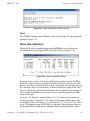
Download Comtech EF Data Vipersat 564L User guide

Transcript
Comtech EF Data is an
AS9100 Rev B / ISO9001:2000 Registered Company
Vipersat
CDD-56X Series
Satellite Network Demodulator Router
User Guide
CDD-562L
CDD-564/564L
MN/22137 Revision 1
Vipersat CDD-56X Series
CDD-562L, CDD-564/564L
Satellite Network Demodulator Router
User Guide
Part number MN/22137
Document Revision 1
Firmware Version 1.6.11/2.6.11
April 21, 2013
COMTECH EF DATA
VIPERSAT Network Products Group
3215 Skyway Court
Fremont, CA 94539
USA
Phone: (510) 252-1462
Fax: (510) 252-1695
www.comtechefdata.com
Part Number: MN/22137
Revision: 1
Firmware Version: 1.6.11/2.6.11
©2013 by Comtech EF Data, Inc. All rights reserved. No part of this manual may be copied or
reproduced without prior written permission of Comtech EF Data, Inc.
IMPORTANT NOTE: The information contained in this document supersedes all previously
published information regarding this product. Product specifications are subject to change
without prior notice.
Comtech reserves the right to revise this publication at any time without obligation to provide
notification of such revision. Comtech periodically revises and improves its products and,
therefore, the information in this document is subject to change without prior notice. Comtech
makes no warranty of any kind with regard to this material, including but not limited to the implied
warranties of merchantability and fitness for a particular purpose. No responsibility for any errors
or omissions that may pertain to the material herein is assumed. Comtech makes no
commitment to update nor to keep current the information contained in this document.
Patents and Trademarks
All products, names and services are trademarks or registered trademarks of their respective
companies. See all of Comtech EF Data’s patents and patents pending at
http://patents.comtechefdata.com.
Printed in the United States of America
Document Revision History
Revision
Date
0
3/10/08
Description
Initial Release
Note: This new document part number, MN/22137, supersedes the
previous CDD-56X User Guide part number, 22137.
New functionality in v1.5.4: New DPC enhancements; STDMA
Power Hunt; Hitless Switching; New VMS registration and Managing
Address method; UDP Port Base Address selection; Auto Home
State Failsafe; SOTM.
1
4/21/13
Update content to reflect NP v1.6.11/2.6.11.
New Features: Dynamic Entry Channel Mode (ECMv2).
{ This Page is Intentionally Blank }
Table of Contents
Chapter 1
General
How to Use This Manual . . . . . . . . . . . 1-1
Manual Organization . . . . . . . . . . . . 1-1
Chapter 1 — General . . . . . . . . . 1-1
Chapter 2 — Quick Start Configuration 1-1
Chapter 3 — Using the Command Line
Interface (CLI) . . . . . . . . . . . . 1-2
Appendix A — Network Addressing . . 1-2
Appendix B — Automatic Switching . . 1-2
Appendix C — Dynamic Power Control1-2
Appendix D — ECM Migration . . . . . 1-2
Appendix E — Glossary . . . . . . . . 1-2
Conventions and References . . . . . . . . 1-2
Product Description . . . . . . . . . . . . . . 1-4
Introduction . . . . . . . . . . . . . . . 1-4
Demodulator Features . . . . . . . . . . 1-4
Router Features . . . . . . . . . . . . . 1-4
Network and Bandwidth Management. . 1-5
Dynamic SCPC (dSCPC) . . . . . . . . 1-5
STDMA . . . . . . . . . . . . . . . . . 1-6
Single Hop On Demand . . . . . . . . . 1-6
Turbo Product Coding . . . . . . . . . . 1-6
Header Decompression . . . . . . . . . 1-6
Payload Decompression. . . . . . . . . 1-7
Data Decryption . . . . . . . . . . . . . 1-7
New in This Release. . . . . . . . . . . . . 1-7
1.6.11/2.6.11 Release . . . . . . . . . . 1-7
Dynamic Entry Channel Mode . . . . . 1-7
Customer Support . . . . . . . . . . . . . . . 1-8
Contact Information . . . . . . . . . . . 1-8
Return Material Authorization . . . . . . 1-8
Reader Comments / Corrections . . . . 1-8
Chapter 2
Quick Start Configuration
Introduction . . . . . . . . . . . . . . .
Initial Configuration . . . . . . . . . . .
Terminal Connection . . . . . . .
Network Role . . . . . . . . . . . .
Setting Vipersat CDD-56X Operating
Parameters . . . . . . . . . . . . .
Set the Feature Configuration . .
Table of Contents
.
.
.
.
.
.
.
.
. 2-1
. 2-2
. . 2-2
. . 2-2
. . . . 2-3
. . . . 2-3
Set the IP Address . . . . . . . . . .
Configure the Route Table . . . . . .
Routing in a Vipersat Network. . . .
Creating the Routes . . . . . . . . .
Set the Satellite Demod Configuration
Set the Vipersat Configuration . . . .
. 2-6
. 2-7
. 2-7
. 2-8
. 2-9
2-10
Chapter 3
Using the Command Line Interface
(CLI)
General . . . . . . . . . . . . . . . . . . . . . 3-1
Common Screen Commands . . . . . . . . 3-2
Demod Select . . . . . . . . . . . . . . 3-2
Save Parameters to Permanent Storage 3-2
Exit . . . . . . . . . . . . . . . . . . . 3-2
Telnet Logout . . . . . . . . . . . . . . 3-2
Menu Descriptions . . . . . . . . . . . . . . . 3-3
Main Menu . . . . . . . . . . . . . . . . . 3-3
Administration . . . . . . . . . . . . . . 3-3
Feature Configuration . . . . . . . . . . . . 3-5
Vipersat Feature Codes . . . . . . . . . 3-5
Vipersat Management . . . . . . . . . . 3-6
Vipersat STDMA . . . . . . . . . . . . 3-6
Vipersat Auto Switching . . . . . . . . . 3-6
Vipersat File Streamer. . . . . . . . . . 3-7
Vipersat Configuration . . . . . . . . . . . . . 3-8
STDMA Mode . . . . . . . . . . . . . . . . 3-8
STDMA . . . . . . . . . . . . . . . . . 3-9
STDMA Tx Rate . . . . . . . . . . . . 3-10
Hub Type . . . . . . . . . . . . . . . 3-10
1 – Fixed . . . . . . . . . . . . . . 3-11
2 – Dynamic Slot . . . . . . . . . . 3-11
3 – Dynamic Cycle . . . . . . . . . 3-11
4 – GIR . . . . . . . . . . . . . . . 3-11
5 – Entry Channel . . . . . . . . . . 3-12
6 – ECMv2 . . . . . . . . . . . . . 3-12
ECMv2 Mode . . . . . . . . . . . . . 3-13
Group ID. . . . . . . . . . . . . . . . 3-14
STDMA Max Power Hunt . . . . . . . 3-14
Low Data Rate Fast Acquisition . . . . 3-15
Burstmap Multicast IP . . . . . . . . . 3-15
Outbound IP . . . . . . . . . . . . . . 3-16
Cycles Per Burst Map . . . . . . . . . 3-16
i
MN/22137, rev 1
Slot Guardband . . . . . . . . . . . . 3-17
Slot Preamble Length . . . . . . . . . 3-18
Slot Data Length . . . . . . . . . . . . 3-18
Nominal Data Length . . . . . . . . . 3-19
Maximum Data Length. . . . . . . . . 3-19
Minimum Data Length . . . . . . . . . 3-20
Total Slot Count . . . . . . . . . . . . 3-20
Slot Cycle Length . . . . . . . . . . . 3-21
Slot Start in Cycle . . . . . . . . . . . 3-21
Set Remotes . . . . . . . . . . . . . . 3-21
Adding a Remote to the STDMA Group .
3-22
Base . . . . . . . . . . . . . . . . . 3-23
Remote Count . . . . . . . . . . . . 3-23
Set Remote Policies . . . . . . . . . 3-24
Delete Remote . . . . . . . . . . . . 3-26
Enable/Disable Remote . . . . . . . 3-27
View Remote(s) . . . . . . . . . . . 3-27
Remove Timeout . . . . . . . . . . 3-28
Remove Retry Timeout . . . . . . . 3-28
LNB LO Frequency . . . . . . . . . . 3-29
Satellite Frequency Conversion . . . . 3-29
STDMA Statistics . . . . . . . . . . . 3-30
Stats Accumulation Window . . . . . 3-30
Clear . . . . . . . . . . . . . . . . . 3-31
Show Hub Statistics . . . . . . . . . . 3-31
STDMA/SCPC Automatic Switching. . . . 3-32
Auto Switching . . . . . . . . . . . . . 3-33
Current WAN Transmit Mode . . . . . 3-34
Load Switching . . . . . . . . . . . . 3-34
STDMA Slot Capacity . . . . . . . . . 3-34
STDMA Switch Delay . . . . . . . . . 3-35
Percent Allocation . . . . . . . . . . . 3-35
Keep Alive Timer for Carrier Inhibit . . 3-36
Hitless Switching Parameters . . . . . 3-36
Delay for Mod . . . . . . . . . . . . 3-37
Delay for Demod . . . . . . . . . . . 3-37
LockTimes . . . . . . . . . . . . . . 3-37
Apply Delay Values . . . . . . . . . 3-38
SOTM Update . . . . . . . . . . . . . 3-38
Unit Role. . . . . . . . . . . . . . . . . . 3-38
Expansion Unit . . . . . . . . . . . . . . 3-39
Network ID. . . . . . . . . . . . . . . . . 3-39
Unit Name . . . . . . . . . . . . . . . . . 3-40
Receive Multicast Address . . . . . . . . 3-40
Managing IP Address . . . . . . . . . . . 3-41
Management Security . . . . . . . . . . . 3-42
Primary Heart Beat . . . . . . . . . . . . 3-44
Home State Revert . . . . . . . . . . . . 3-44
ii
Dynamic Power Control Configuration . . 3-44
DPC Enabled . . . . . . . . . . . . . 3-46
Speed Up EbNo . . . . . . . . . . . . 3-46
Target DPC Address . . . . . . . . . 3-46
Set Home State Parameters . . . . . . . 3-47
Set Current Configuration as Home State. .
3-48
Force Modem to Home State . . . . . 3-48
STDMA State . . . . . . . . . . . . . 3-49
Receive Frequency . . . . . . . . . . 3-49
Receive Data Rate . . . . . . . . . . 3-49
Receive FEC Type . . . . . . . . . . 3-50
Receive Coding Rate . . . . . . . . . 3-50
Receive Modulation Type . . . . . . . 3-51
Vipersat Summary . . . . . . . . . . . . 3-51
Vipersat Migration . . . . . . . . . . . . . 3-52
UDP Port Base Address . . . . . . . . . 3-53
Alerts . . . . . . . . . . . . . . . . . . . 3-53
Appendix A
Network Addressing
Introduction . . . . . . . . . . . . . . . . .
The OSI Reference Model . . . . . . . . .
Layers 1 – 3 . . . . . . . . . . . . . . .
Binary Math . . . . . . . . . . . . . . . . .
IP Addressing . . . . . . . . . . . . . . . .
IP Address Classes . . . . . . . . . . .
Class A . . . . . . . . . . . . . .
Class B . . . . . . . . . . . . . .
Class C . . . . . . . . . . . . . .
Class D . . . . . . . . . . . . . .
Class E . . . . . . . . . . . . . .
Private Network IP Addresses . . .
Network Address Translation (NAT).
Subnets . . . . . . . . . . . . . . . . .
Subnet Mask . . . . . . . . . . . . . .
Network Segments . . . . . . . . . . .
Default Gateways . . . . . . . . . . . .
MAC Addresses . . . . . . . . . . . . .
.
.
.
.
.
.
.
.
.
.
.
.
.
.
.
.
.
.
A-1
A-2
. A-2
A-4
A-6
. A-6
. A-6
. A-6
. A-7
. A-7
. A-8
. A-8
. A-8
. A-8
. A-9
A-10
A-11
A-11
Appendix B
Automatic Switching
General . . . . . . .
Hitless Switching
Load Switching . . .
Overview . . . .
.
.
.
.
.
.
.
.
.
.
.
.
.
.
.
.
.
.
.
.
.
.
.
.
.
.
.
.
.
.
.
.
.
.
.
.
.
.
.
.
.
.
.
.
.
.
.
.
. B-1
. . B-2
. B-4
. . B-4
Vipersat CDD-56X Series User Guide
MN/22137, rev 1
Bandwidth Allocation and Load Switching by
the Hub STDMA Burst Controller . . .B-5
Load Switching—STDMA Hub . . . . . . .B-8
Hub Switching Parameters . . . . . . .B-8
Hub Switching Process . . . . . . . . .B-9
Load Switching—Remote . . . . . . . . . B-10
Remote Switching Parameters . . . . B-10
Determination for Switching . . . . . . B-12
Load Switch Example . . . . . . . . . . . B-13
Reduced Data Flow in Switched Mode
(SCPC) . . . . . . . . . . . . . . . B-14
Application Switching . . . . . . . . . . . . . B-16
ToS Switching . . . . . . . . . . . . . . . . . B-18
ToS Background . . . . . . . . . . . . . . B-18
Detection of ToS Stamped Packets . . B-19
Configuration . . . . . . . . . . . . . B-20
Example Implementations . . . . . . . . . B-21
ToS Switching Per Device . . . . . . . B-21
ToS Switching Per Traffic Type . . . . B-21
ToS Remarking . . . . . . . . . . . . B-22
ToS to DSCP Value Conversions . . . B-23
Mesh Setup Based on ToS Detection . B-24
Entry Channel Mode Switching . . . . . . . . B-25
STDMA Entry Channel Mode . . . . . . . B-25
Fail-Safe Operation . . . . . . . . . . B-26
Using STDMA ECM . . . . . . . . . . B-28
Switching an ECM Remote from SCPC to
STDMA . . . . . . . . . . . . . . . B-29
Dynamic Entry Channel Mode. . . . . . . B-31
Hub Configuration . . . . . . . . . . . B-32
Remote Configuration . . . . . . . . . B-33
ECM Processing . . . . . . . . . . . . B-34
Calibrated Data Rate . . .
DPC Margin . . . . . . . .
Nominal Power Level . . .
Max Data Rate . . . . . .
Max Code Rate . . . . . .
Max Modulation . . . . . .
Max FEC Type . . . . . .
Calculate Max Power . . .
Max Power . . . . . . . .
Signal Power Level Considerations.
Power Considerations. . . . . .
Cabling Considerations . . . . .
.
.
.
.
.
.
.
.
.
.
.
.
.
.
.
.
.
.
.
.
.
.
.
.
.
.
.
.
.
.
.
.
.
.
.
.
.
.
.
.
.
.
.
.
.
.
.
.
.
.
.
.
.
.
.
.
.
.
.
.
C-13
C-13
C-13
C-13
C-13
C-13
C-13
C-13
C-14
C-15
C-16
C-16
.
.
.
.
.
.
.
.
.
.
.
.
.
.
.
.
. D-1
. D-3
. . D-3
. . D-5
Appendix D
ECM Migration
General . . . . . . . . . . .
Migration Procedure . . . .
Configure Remote Units.
Configure Hub Unit . . .
.
.
.
.
.
.
.
.
.
.
.
.
.
.
.
.
Appendix E
Glossary
. . . . . . . . . . . . . . . . . . . . . . . . . E-1
Appendix C
Dynamic Power Control
Introduction . . . . . . . . . . . .
Description . . . . . . . . . . . .
BER Waterfall Mapping . .
Delta Power Compensation
Theory of Operation . . . . . .
Configuration . . . . . . . . . . .
Main DPC Menu . . . . . . . .
Enable DPC . . . . . . .
Target Eb/No . . . . . .
Speed Up Eb/No Range .
Target DPC (IP) Address
Calculate Max Power Menu . .
Table of Contents
.
.
.
.
.
.
.
.
.
.
.
.
.
.
.
.
.
.
.
.
.
.
.
.
.
.
.
.
.
.
.
.
.
.
.
.
.
.
.
.
.
.
.
.
.
.
.
.
.
.
.
.
.
.
.
.
.
.
.
.
. C-1
. C-3
. .C-3
. .C-3
. .C-4
. C-7
. .C-9
. C-10
. C-10
. C-11
. C-11
. C-11
iii
MN/22137, rev 1
{ This Page is Intentionally Blank }
iv
Vipersat CDD-56X Series User Guide
List of Figures
Chapter 2 Figures
Figure 2-1 Main Menu screen. . . . . . . . . . . . . . 2-4
Figure 2-2 Administration screen . . . . . . . . . . . 2-4
Figure 2-3 Feature Configuration screen . . . . . 2-5
Figure 2-4 FAST Feature Code dialog . . . . . . . 2-5
Figure 2-5 Working Mode dialog . . . . . . . . . . . 2-6
Figure 2-6 Ethernet Interface screen . . . . . . . . 2-7
Figure 2-7 Configuring the Route Table screen 2-9
Figure 2-8 Rx Configuration screen . . . . . . . . 2-10
Figure 2-9 Vipersat Configuration screen (Hub). .
2-10
Chapter 3 Figures
Figure 3-1 Main Menu screen. . . . . . . . . . . . . . 3-3
Figure 3-2 Administration screen . . . . . . . . . . . 3-4
Figure 3-3 Working Mode dialog . . . . . . . . . . . 3-4
Figure 3-4 Feature Configuration screen . . . . . 3-5
Figure 3-5 FAST Feature Code dialog . . . . . . . 3-6
Figure 3-6 Vipersat Configuration screen (Hub)3-8
Figure 3-7 STDMA screen (Hub, STDMA, Fixed
type). . . . . . . . . . . . . . . . . . . . . . . . . . . . 3-9
Figure 3-8 STDMA screen (Hub/Remote, SCPC)
3-9
Figure 3-9 Hub Type prompt . . . . . . . . . . . . . 3-10
Figure 3-10 ECMv2 Mode prompt . . . . . . . . . 3-13
Figure 3-11 Group ID prompt . . . . . . . . . . . . . 3-14
Figure 3-12 STDMA Max Power Hunt prompt 3-15
Figure 3-13 Burstmap Multicast IP prompt . . . 3-16
Figure 3-14 Outbound IP prompt . . . . . . . . . . 3-16
Figure 3-15 Cycles per Burst Map prompt . . . 3-17
Figure 3-16 Slot Guardband prompt. . . . . . . . 3-17
Figure 3-17 Slot Preamble Length prompt . . . 3-18
Figure 3-18 Slot Data Length prompt . . . . . . . 3-19
Figure 3-19 Nominal Data Length prompt . . . 3-19
Figure 3-20 Maximum Data Length prompt . . 3-20
Figure 3-21 Minimum Data Length prompt. . . 3-20
Figure 3-22 Total Slot Count prompt . . . . . . . 3-21
Figure 3-23 STDMA Remotes Menu screen . 3-22
Figure 3-24 Remote Name and IP Address prompt
3-22
Figure 3-25 Base Remote Display prompt . . . 3-23
Figure 3-26 STDMA Remote Policies screen (GIR
List of Figures
Hub) . . . . . . . . . . . . . . . . . . . . . . . . . . .3-24
Figure 3-27 GIR Remote Policies prompt . . . .3-25
Figure 3-28 Entry Channel Switch Rates screen .
3-25
Figure 3-29 Remote SCPC Data Rate prompt3-26
Figure 3-30 Global SCPC Data Rate prompt .3-26
Figure 3-31 Global Switch Type prompt . . . . .3-26
Figure 3-32 Delete Remote prompt . . . . . . . .3-27
Figure 3-33 Enable/Disable Remote prompt .3-27
Figure 3-34 View Remote(s) screen . . . . . . . .3-27
Figure 3-35 Remove Timeout prompt . . . . . . .3-28
Figure 3-36 Remove Retry Timeout prompt . .3-28
Figure 3-37 LNB LO Frequency prompt . . . . .3-29
Figure 3-38 Satellite Frequency Conversion prompt
3-29
Figure 3-39 STDMA Statistics screen (Hub). .3-30
Figure 3-40 STDMA Statistics screen (Remote). .
3-30
Figure 3-41 Stats Accumulation Window prompt .
3-31
Figure 3-42 Show Hub Statistics screen. . . . .3-31
Figure 3-43 Automatic Switching screen . . . .3-33
Figure 3-44 STDMA Slot Capacity prompt . . .3-34
Figure 3-45 STDMA Switch Delay prompt . . .3-35
Figure 3-46 Percent Allocation prompt . . . . . .3-35
Figure 3-47 Keep Alive Timer for Carrier Inhibit
prompt . . . . . . . . . . . . . . . . . . . . . . . . .3-36
Figure 3-48 Hitless Switching screen . . . . . . .3-37
Figure 3-49 Set LockTime prompt . . . . . . . . .3-38
Figure 3-50 Unit Role prompt . . . . . . . . . . . . .3-38
Figure 3-51 Expansion Unit prompt . . . . . . . .3-39
Figure 3-52 Network ID prompt . . . . . . . . . . .3-40
Figure 3-53 Unit Name prompt . . . . . . . . . . . .3-40
Figure 3-54 Receive Multicast IP Address prompt
3-41
Figure 3-55 Managing IP Address prompt . . .3-41
Figure 3-56 Vipersat Management Security screen
3-43
Figure 3-57 Encryption Key Entry prompt. . . .3-43
Figure 3-58 DPC Configuration screen (Hub,
STDMA) . . . . . . . . . . . . . . . . . . . . . . . .3-45
Figure 3-59 DPC Configuration screen (Hub/
Remote, SCPC) . . . . . . . . . . . . . . . . . .3-45
Figure 3-60 Speed Up EbNo prompt . . . . . . .3-46
Figure 3-61 Target DPC Address prompt . . . .3-47
v
MN/22137, rev 1
Figure 3-62
Figure 3-63
3-49
Figure 3-64
Figure 3-65
Figure 3-66
Figure 3-67
Figure 3-68
Figure 3-69
Figure 3-70
Figure 3-71
Home State Configuration screen3-48
Force Modem to Home State warning
Receive Frequency prompt . . . . . 3-49
Receive Data Rate prompt . . . . . 3-50
Receive FEC Type prompt . . . . . 3-50
Receive Coding Rate prompt . . . 3-50
Receive Modulation Type prompt 3-51
Vipersat Summary screen. . . . . . 3-51
Vipersat Migration prompt . . . . . . 3-53
UDP Port Base Address prompt . 3-53
Appendix A Figures
Figure A-1 The Seven OSI Protocol Layers . . .A-2
Figure A-2 Bits and Bytes. . . . . . . . . . . . . . . . .A-4
Figure A-3 Binary to Decimal Conversion . . . .A-4
Figure A-4 IP Address Classes A, B, C . . . . . .A-7
Figure A-5 NAT Router Example . . . . . . . . . . .A-8
Figure A-6 Default Subnet Masks for IP Classes .
A-9
Figure A-7 ANDing an IP address and a subnet
mask . . . . . . . . . . . . . . . . . . . . . . . . . .A-10
Figure A-8 Network Segments . . . . . . . . . . . .A-10
Figure A-9 Router as Default Gateway. . . . . .A-11
Figure A-10 Network Node MAC Addresses .A-12
Appendix B Figures
Figure B-1 Hitless Switching screen. . . . . . . . .B-2
Figure B-2 Auto Switching Menu, CDM-570/570L
Hub . . . . . . . . . . . . . . . . . . . . . . . . . . . .B-8
Figure B-3 Hub Load Switching Page, SLM-5650A
B-8
Figure B-4 Auto Switching Menu, CDM-570/570L
Remote . . . . . . . . . . . . . . . . . . . . . . . .B-11
Figure B-5 Remote Load Switching Page, SLM5650A . . . . . . . . . . . . . . . . . . . . . . . . .B-11
Figure B-6 Load Switching diagram . . . . . . . .B-13
Figure B-7 Application Switching diagram . . .B-16
Figure B-8 ToS Field Location within the IP Header
B-18
Figure B-9 Remote ToS Switching menu . . . .B-20
Figure B-10 Per Device ToS Switching Example .
B-21
vi
Figure B-11 Per Type ToS Switching Example . .
B-22
Figure B-12 ToS Remarking Application . . . B-23
Figure B-13 ToS and DSCP Conversion Chart . .
B-23
Figure B-14 ECM Switch Recovery: < 3 minutes .
B-27
Figure B-15 ECM Switch Recovery: > 3 minutes .
B-28
Figure B-16 STDMA Page with Entry Channel
Mode, CDM-570/570L . . . . . . . . . . . . B-29
Figure B-17 ECM Remote List Page, CDM-570/
570L . . . . . . . . . . . . . . . . . . . . . . . . . . B-30
Figure B-18 Remote Bandwidth Entry, CDM-570/
570L . . . . . . . . . . . . . . . . . . . . . . . . . . B-30
Figure B-19 Revert Uplink Carrier Command, VMS
modem . . . . . . . . . . . . . . . . . . . . . . . . B-31
Figure B-20 Entry Channel Mode v2 Configuration,
Hub (CDD-564L) . . . . . . . . . . . . . . . . B-33
Figure B-21 Entry Channel Mode v2 Configuration,
Remote (CDM-570L) . . . . . . . . . . . . . B-34
Figure B-22 ECMv2 Processing Diagram . . . B-35
Appendix C Figures
Figure C-1 Data Rate to Power Relationship, DPC
C-5
Figure C-2 Excessive Max Power Example . . C-6
Figure C-3 DPC Configuration screen, CLI . . C-9
Figure C-4 DPC dialog, Parameter Editor . . C-10
Figure C-5 DPC Calculate Max Power screen, CLI
C-12
Figure C-6 DPC Calibration dialog, Parameter
Editor . . . . . . . . . . . . . . . . . . . . . . . . . C-12
Figure C-7 Signal Power Levels, Remote SiteC-15
Appendix D Figures
Figure D-1 STDMA Configuration Page, Remote
CDM-570/L. . . . . . . . . . . . . . . . . . . . . . D-4
Figure D-2 STDMA Configuration Menu, Hub Type
Selection . . . . . . . . . . . . . . . . . . . . . . . D-5
Figure D-3 STDMA Menu, ECMv2 Hub Type . D-6
Figure D-4 Switch Rate Limits, InBand Return Path
Settings Page. . . . . . . . . . . . . . . . . . . . D-7
Vipersat CDD-56X Series User Guide
List of Tables
Chapter 2 Tables
Table 2-1 CDD-56X Network Roles and Functions
2-3
Table 2-2 Vipersat Feature Configuration . . . . 2-6
Appendix B Tables
Table B-1 STDMA ACK Message . . . . . . . . . .B-6
Table B-2 ToS Switching Settings . . . . . . . . .B-20
Appendix C Tables
Table C-1 DPC Parameters, Main Menu . . . . .C-7
Table C-2 DPC Parameters, Calculate Max Power
Menu . . . . . . . . . . . . . . . . . . . . . . . . . . .C-8
Table C-3 Typical Coaxial Cable Characteristics .
C-17
List of Tables
vii
MN/22137, rev 1
{ This Page is Intentionally Blank }
viii
Vipersat CDD-56X Series User Guide
CHAPTER
GENERAL
How to Use This Manual
This manual documents the enhanced Vipersat features and functions of the
CDD-56X Series (CDD-562L, CDD-564, and CDD-564L) of Satellite Network
Demodulator Routers, and guides the user in how to configure these products
for use in a Vipersat network. The material covered addresses only those areas
specific to a CDD-56X running in Vipersat mode, and complements the universal features and functions described in the CDD-564L Installation and Operation Manual.
Earth station engineers, technicians, and operators responsible for the configuration and maintenance of the CDD-56X are the intended audience for this
document.
Manual Organization
This User’s Guide is organized into the following sections:
Chapter 1 — General
Contains CDD-56X product description, customer support information, and
manual conventions and references.
Chapter 2 — Quick Start Configuration
Covers the initial basic steps that are necessary for configuring the CDD-56X
from a factory default state to a functional network element.
C h ap t e r 1 - G e n e r a l
1-1
H o w t o U s e T h i s Ma n u a l
MN/22137, rev 1
Chapter 3 — Using the Command Line Interface (CLI)
Describes the use of the CLI for configuring and monitoring the CDD-56X in a
Vipersat network. Each CLI screen is presented along with a detailed description and related commands.
Appendix A — Network Addressing
Supplemental reference information on binary math and network addressing to
assist with integrating the CDD-56X into a Vipersat network.
Appendix B — Automatic Switching
Supplemental reference information on the Vipersat feature that provides load
switching (response to network traffic load), application switching (response to
traffic type) functions, and Entry Channel Mode switching functions.
Appendix C — Dynamic Power Control
A description of Vipersat’s DPC feature and its functionality in a network of
CDM-570/CDD-56X series equipment.
Appendix D — ECM Migration
Procedural instructions on migrating a Vipersat network of CDM-570/CDD56X series equipment from STDMA Entry Channel Mode (ECMv1) to Dynamic
Entry Channel Mode (ECMv2).
Appendix E — Glossary
A glossary of terms that pertain to Vipersat satellite network technology.
Conventions and References
The following conventions are utilized in this manual to assist the reader:
NOTE
Note: Provides important information relevant to the accompanying
text.
Tip: Provides complementary information that facilitates the
associated actions or instructions.
1-2
Vipersat CDD-56X Series User Guide
MN/22137, rev 1
H o w t o U s e T h i s M a n u al
Caution: Explanatory text that notifies the reader of possible
consequences of an action.
Warning: Explanatory text that notifies the reader of potential harm
as the result of an action.
The following documents are referenced in this manual, and provide supplementary information for the reader:
• CDD-564L L-Band Quad Demodulator with IP Module Installation and
Operation Manual (Part Number MN/CDD564L.IOM)
• CDM-570/570L Modem Installation and Operation Manual (Part Number
MN/CDM570L.IOM)
• Vipersat CDM-570/570L User Guide (Part Number MN/22125)
• Vipersat CDM-570/L, CDD-56X Parameter Editor User Guide (Part
Number MN-0000038)
• Vipersat Management System User Guide (Part Number MN/22156)
• VLoad Utility User Guide (Part Number MN/22117)
C h ap t e r 1 - G e n e r a l
1-3
Product Description
MN/22137, rev 1
Product Description
Introduction
The Vipersat CDD-56X Satellite Network Demodulator Router is ideal for
operators wishing to supply mesh connectivity between sites, while keeping
network infrastructure costs down. The CDD-564 and CDD-564L provide four
separate demodulators (the CDD-562L provides two) and an integrated router in
a compact, cost-effective 1RU package.
The CDD-56X simplifies Hub site installations by reducing rack space and cost
with 2/4 independent demodulators in a single chassis. A bank of CDD-56X
demodulators is ideal for a star network consisting of a single outbound carrier
at the Hub with multiple carriers returned from the remote sites.
The CDD-56X can be used at Hub sites where multiple burst controllers are
needed. Demodulator roles are defined via software, configurable either as a
burst controller in STDMA (Selective Time Division Multiple Access) mode, or
as dedicated SCPC (Single Channel per Carrier) inbounds from remote terminals.
At Remote sites, the CDD-56X supports mesh connectivity between multiple
sites. Operating in mesh topology with links directly between sites eliminates
double-hops through the Hub, conserving bandwidth and reducing latency.
Demodulator Features
• 50–90 MHz or 100–180 MHz IF Range, each Demodulator (CDD-564)
950–1950 MHz IF Range, each Demodulator (CDD-562L/564L)
• QPSK, 8-PSK, and 16-QAM Operation
• Data Rate Range from 16 kbps up to 9.98 Mbps, depending on modulation
and FEC used (with FAST feature upgrade)
• Turbo Product Coding (TPC) FEC
• Fast Acquisition Demodulator
• Simultaneous STDMA (burst) and dSCPC modes (configurable on a per
demodulator basis)
• LNB Support: 10 MHz Reference and LNB Power
• N:M Hub Modem Redundancy Schemes
Router Features
• Fully Integrated Network Management using Vipersat Management
System (VMS)
1-4
Vipersat CDD-56X Series User Guide
MN/22137, rev 1
P r o d u c t D e s c r i p t io n
• Single Hop On Demand (SHOD) functions
• 10/100BaseT Ethernet LAN/WAN Interface
• Static IP Routing for Unicast or Multicast
• Header Decompression
• Payload Decompression
• 3xDES Decryption
Network and Bandwidth Management
A Vipersat-powered network solution integrates this advanced demodulator/
router with the powerful network management tool, the Vipersat Management
System (VMS). The VMS provides for traditional monitor and control of the
CDM-570/570L modems and the CDD-56X demodulators, but more than just
an M&C package, the VMS offers unique bandwidth management that is ideal
for IP-switched networks. Short data transfers are typically executed using a
shared Selective Time Division Multiple Access (STDMA) channel, and when
large amounts of data transfer, voice, and/or video communications are needed,
these units can be automatically switched to a dedicated SCPC channel.
Dynamic SCPC (dSCPC)
The VMS provides for dynamic bandwidth allocation while in SCPC mode,
automatically altering the bandwidth based on traffic conditions. This effectively enables the network to better handle connection-oriented applications and
reduce network congestion, jitter, and latency.
In a typical Vipersat application used in conjunction with CDM-570/570L
modems, the CDD-56X demodulators are drawn from a pool for assignment to a
connection-oriented link.
Traffic inbounds from remotes can be switched manually or automatically,
application or load triggered, or scheduled, from shared STDMA (burst) mode
to a dedicated SCPC connection. The VMS automatically assigns a free demodulator at the Hub to a desired remote inbound, completely eliminating manual
intervention. At remote sites, the CDD-56X simplifies Single Hop On Demand
(SHOD) applications with direct remote-to-remote connections that do away
with double-hops. Once the session is completed, the remote is automatically
reverted back to its home state.
The result is an economical and flexible network with bandwidth shared and
directed where it is needed for any mix of IP voice, video, and data traffic.
C h ap t e r 1 - G e n e r a l
1-5
Product Description
MN/22137, rev 1
STDMA
The addition of STDMA capability to a Vipersat network allows multiple terminals to share the same satellite resources that would be dedicated to a single
terminal in an SCPC configuration. This means that more terminals can be
added to the network with minimal additional cost in either satellite bandwidth
or Hub Terminal hardware.
Vipersat STDMA thus provides a low cost solution for medium to large sized
networks with generally moderate bandwidth requirements, while at the same
time providing all the features of the existing Vipersat systems, including the
availability of a switched pool of SCPC channels for occasional high bandwidth
traffic such as video conferences and large file transfers. Each STDMA
upstream channel from the remote terminals to the Hub uses an STDMA frame
operating at an aggregate data rate of from 16 kbps to 9.98 Mbps and can
support up to hundreds of remote terminals with multiple burst channel
inbounds.
Configured as a Hub terminal, the CDD-564/564L provides one demod for
receiving an upstream STDMA channel from the remotes, and three demods for
receiving three SCPC channels.
Single Hop On Demand
The CDD-56X is ideal for mesh applications such as Vipersat's Single Hop On
Demand (SHOD). With the CDD-56X, SHOD (meshed) circuits are easily and
economically established between remotes. SHOD provides significant and
dynamic connectivity between latency connections without suffering the high
costs associated with multiple carriers and/or 1-to-1 multi-receiver links.
Turbo Product Coding
The Comtech Vipersat CDD-56X incorporates a Turbo Product Codec (TPC)
error correction, delivering significant performance improvement when
compared to Viterbi with concatenated Reed-Solomon. TPC simultaneously
offers increased coding gain, lower decoding delay, and significant bandwidth
savings.
Header Decompression
Header compression reduces the required Voice over Internet Protocol (VoIP)
bandwidth by as much as 60%. Example: a G.729 voice codec operating at 8
kbps will occupy 32 kbps once encapsulated into IP framing on a LAN. Using
IP/UDP/RTP Header Compression, the same traffic only needs 10.8 kbps total
WAN satellite bandwidth to cross the link. The CDD-56X demods perform
header decompression prior to passing the data onto the LAN.
1-6
Vipersat CDD-56X Series User Guide
MN/22137, rev 1
P r o d u c t D e s c r i p t io n
Payload Decompression
Payload compression condenses the size of data frames and reduces the satellite
bandwidth required to transmit across the link. Configurable on a per route
basis, Payload Compression provides traffic optimization and reduces bandwidth up to 40%. The CDD-56X demods perform payload decompression prior
to passing the data onto the LAN.
Data Decryption
The CDD-56X decrypts 3xDES data that it receives. Data encryption, configurable on a per route basis, is used to prevent unauthorized access to data over the
satellite link.
New in This Release
The following firmware version incorporates a number of additional features
and enhancements.
1.6.11/2.6.11 Release
Dynamic Entry Channel Mode
Dynamic ECM (ECMv2) utilizes a modified slotted Aloha method for Remotes
to establish registration in the network and obtain the means for switching into
dSCPC mode. Rather than sharing an STDMA burst map, as is the method with
STDMA ECM, the Remotes rely on communicating with the Hub channel
controller through the use of a multicast Transmission Announcement Protocol
(TAP) message. This eliminates the restriction in the number of Remotes in an
Entry Channel group that is inherent with the burst map method.
C h ap t e r 1 - G e n e r a l
1-7
C u s t o m e r S up p o r t
MN/22137, rev 1
Customer Support
Contact Information
Contact Comtech Vipersat Networks Customer Support for information or
assistance with product support, service, or training on any Vipersat product.
Mail:
3215 Skyway Court
Fremont, CA 94539
USA
Phone:
1+510-252-1462 ext. 2
Fax:
1+510-252-1695
Email:
[email protected]
Web:
www.comtechefdata.com
Return Material Authorization
Any equipment returned to Vipersat must have a Return Material Authorization
(RMA) issued prior to return. To return a Comtech Vipersat Networks product
for repair or replacement:
• Obtain an RMA form and number from Vipersat Customer Support.
• Be prepared to supply the product model number and serial number of the
unit.
• To ensure safe shipping of the product, pack the equipment in the original
shipping carton.
Reader Comments / Corrections
If the reader would like to submit any comments or corrections regarding this
manual and its contents, please forward them to a Vipersat Customer Support
representative. All input is appreciated.
1-8
Vipersat CDD-56X Series User Guide
CHAPTER
QUICK START CONFIGURATION
Introduction
This chapter describes the minimum configuration of a Vipersat CDD-56X
Series Demodulator Router that is necessary in order for the equipment to function in a Vipersat network.
The Vipersat CDD-56X Demodulator Router stores its configuration in an
ASCII file named the PARAM file. Equipment Configuration is typically
performed through the use of the Command Line Interface (CLI), particularly
the initial configuration. Once the equipment is functioning in the network,
additional configuration can be performed via the VMS.
Refer to Chapter 3, “Using the Command Line Interface (CLI)”, for a detailed
description on the usage of this feature.
This manual covers the configuration specifics of the CDD-56X when used in a
Vipersat network. Refer to the CDD-564L L-band Quad Demodulator Installation and Operation Manual for general instruction on setting up, installing and
configuring this equipment.
NOTE
Note: Before attempting to configure a CDD-56X to be used in a Vipersat
network, make certain it has the Vipersat option installed and enabled.
C h ap t e r 2 - Q u i c k S t a r t C o n f i g u r a t i o n
2-1
I n i t i a l C o n f i gu r a t i o n
MN/22137, rev 1
Initial Configuration
NOTE
Note: Many of the settings required for equipment configuration are based on
the LAN/WAN and Satellite network design, and should be obtained from
the network administrator.
Terminal Connection
These procedures are performed using the CLI from a workstation connected to
the CDD-56X either via a direct connection to the Console port (a console cable
is shipped with each unit), or via a telnet connection to the Traffic 100 port.
Alternatively, HyperTerminal or any of the other connection methods described
in the CDD-564L L-band Quad Demodulator Installation and Operation
Manual may be used.
Make a terminal connection to the target CDD-56X demodulator/router. If
connecting via the Traffic 100 Ethernet port (do not use the M&C port), enter
the IP address of the unit. The factory default IP address for a Vipersat enabled
unit is 192.168.254.2. Configure the terminal for VT-100 emulation mode.
Once a terminal connection has been made, the CDD-56X will respond with a
Login prompt. The factory defaults for accessing the Admin level are:
Login: comtech
Password: comtech
Once the operator has logged in, the Main Menu shown in figure 2-1 is
displayed.
Network Role
The first and most important step prior to configuring the CDD-56X is to define
its network role.
The CDD-56X is a flexible network component able to perform different functions depending on how it is used in a network. The role that is defined for each
CDD-56X will determine what functions are available for each unit to fill its
role. Table 2-1 lists the network roles and the corresponding network functions
for which the CDD-56X can be configured.
2-2
Vipersat CDD-56X Series User Guide
MN/22137, rev 1
I n i t i a l C o n f i g u r a t io n
Table 2-1 CDD-56X Network Roles and Functions
Demod
Role / Location
Expansion
1
2
3
4
Hub
Hub
Remote
No
Yes
Yes
STDMA
SCPC
SCPC
SCPC
SCPC
SCPC
SCPC
SCPC
SCPC
SCPC
SCPC
SCPC
The procedure for setting the modem configuration to match the defined
network role is presented later in this Quick Start (“Set the Vipersat Configuration” on page 2-10).
Refer to the section “Unit Role” on page 3-38, and the following section
“Expansion Unit”, for additional details on setting a CDD-56X’s network role.
Setting Vipersat CDD-56X Operating Parameters
The following is an example of using the CLI to bring a Vipersat CDD-56X
with factory default settings to the configuration which allows the Vipersat
functions to be accessible.
Set the Feature Configuration
The operating parameters that will be configured in the target CDD-56X are, in
part, determined by the role the CDD-56X is to fill in the network, as shown in
table 2-1 and table 2-2.
Use the following procedure to configure a CDD-56X to the network role it is to
fill in a Vipersat network.
1.
From the Main Menu shown in figure 2-1, select the Administration
command by entering A at the command prompt.
C h ap t e r 2 - Q u i c k S t a r t C o n f i g u r a t i o n
2-3
I n i t i a l C o n f i gu r a t i o n
MN/22137, rev 1
Figure 2-1 Main Menu screen
2.
From the Administration screen shown in figure 2-2, select the Features
Configuration command by entering F at the command prompt.
Figure 2-2 Administration screen
3.
2-4
From the Feature Configuration menu shown in figure 2-3, verify
whether or not the Vipersat Feature Codes are Available (appears as
shown in the figure). These codes are entered prior to shipment from the
factory; however, if the codes display as Unavailable, they will have to be
re-entered.
Vipersat CDD-56X Series User Guide
MN/22137, rev 1
I n i t i a l C o n f i g u r a t io n
Figure 2-3 Feature Configuration screen
To enter the feature code, enter Y at the command prompt, then enter the 20
digit FAST Feature Code, as shown in figure 2-4.
Figure 2-4 FAST Feature Code dialog
Tip: The network administrator will have the FAST Feature codes. These are
generated and stored by the unit serial number for the target CDD-56X.
The target unit’s serial number can be found on the rear of the unit
chassis.
4.
After entering the FAST Feature code, return to the Administration screen,
shown in figure 2-2, and ensure that the Working Mode is set to RouterVipersat.
If it is not, enter C and change the setting by selecting 4, as shown in
figure 2-5. The unit will reboot automatically in order to implement the
change for this setting.
C h ap t e r 2 - Q u i c k S t a r t C o n f i g u r a t i o n
2-5
I n i t i a l C o n f i gu r a t i o n
MN/22137, rev 1
Figure 2-5 Working Mode dialog
5.
When the reboot is completed, return to the Feature Configuration menu
and configure the settings for Vipersat STDMA and Auto Switching
according to the table below.
Table 2-2
Unit Role
Hub
Hub Expansion
Remote Expansion
6.
Vipersat Feature Configuration
Vipersat
STDMA
Auto Switching
Enabled
Enabled
Enabled
Enabled
Disabled
Disabled
(optional) Enabled
Disabled
Disabled
Save the settings to flash by entering S at the command prompt.
Set the IP Address
2-6
1.
From the Main Menu, enter I to access the Interface Configuration menu
screen, then enter E to access the Ethernet Interface screen (figure 2-6).
2.
Enter I at the command prompt, and enter the IP address for this unit.
Vipersat CDD-56X Series User Guide
MN/22137, rev 1
I n i t i a l C o n f i g u r a t io n
Figure 2-6 Ethernet Interface screen
3.
Save the settings to flash by entering S at the command prompt.
Configure the Route Table
Routing in a Vipersat Network
CDD-56X Demodulator Routers operating in Vipersat mode do not use the
small or large network described in the CDD-564L Installation and Operation
Manual. There is no HDLC address in a Vipersat network; instead, the
CDD-56X role designation — Hub or Remote, Expansion unit or not — determines routing rules that prevent multicast loops. This simplifies the configuration of a Vipersat network.
Because satellite networks are often used as extensions for access to services
such as the Internet or the PSTN, they lend themselves quite readily to private
addressing. For example, to provide Internet access to the satellite network, only
the Hub requires a public IP address in order for the entire satellite network that
is controlled by the Hub to have access to the Internet backbone. Utilizing
Network Address Translation (NAT), the administrator can effectively address
the network using a minimum number of static route statements.
Example:
The IP address 172.16.0.0 is the private address network number for class B
networks. If there is a router at the Hub with a connection to the Internet, the
operator can define the local network as a class B. If the operator splits the Class
B in half and points the upper half toward the satellite there will be over 16000
usable addresses at the Hub as well as at the Remotes. For details on IP addressing, refer to Appendix A, "Network Addressing".
C h ap t e r 2 - Q u i c k S t a r t C o n f i g u r a t i o n
2-7
I n i t i a l C o n f i gu r a t i o n
MN/22137, rev 1
By putting the one route statement “Remotes 172.16.128.0/17 Wan to Sat” in
the TDM Hub modem, and by using the route statement “GW 0.0.0.0/0 Wan to
Sat” at each of the remote modems, the network will successfully route packets.
The remotes can then be sub-netted as class C networks or below. Additional
routers at the remotes can be added for unusually large sites, allowing an additional layer of NAT without requiring any more explicit routing within the
Vipersat Modem/Routers.
Refer to the CDD-564L Installation and Operation Manual for additional information on entering routes.
Creating the Routes
The following procedure outlines the basic route structure that the target
CDD-56X will require for its role in the network. One of the key routes that
must be created is a gateway address for routing the data traffic that is received
by the unit.
1.
From the Main Menu shown in figure 2-1, select Route Table by entering
R at the command prompt.
2.
From the Configuring the Route Table screen shown in figure 2-7, enter
1 at the command prompt to set the first route that will define the default
gateway.
In a Hub configuration, the default gateway will typically point to a router
on the same LAN as the CDD-56X Hub unit.
In a Remote configuration, the default route will typically point to the
satellite modem used for communications back to the Hub.
3.
When prompted, enter the Route Name (GW), the IP Address, the
Number of Bits in the subnet mask, the Route Interface (Ethernet or Satellite), and the Next Hop address. The system administrator can supply
this information, if necessary.
In a Hub role, for example, enter the name of the route (e.g., GW), enter
0.0.0.0 for the destination IP address and 0 for the mask, enter E for
Ethernet interface, then enter the IP address of the appropriate router or
modem for the next hop.
2-8
Vipersat CDD-56X Series User Guide
MN/22137, rev 1
I n i t i a l C o n f i g u r a t io n
Figure 2-7 Configuring the Route Table screen
4.
Enter S at the command prompt in figure 2-7 to save the settings to flash.
Set the Satellite Demod Configuration
1.
Enter M from the Main Menu, then enter C from the Satellite
Demodulator menu to access the Configuration screen.
2.
Enter R to access the Rx Configuration screen shown in figure 2-8. Set
the Rx parameters for Frequency, Data Rate, FEC, Code Rate, and
Modulation as specified by the network administrator.
The Receive parameters must be set for each Demod. Enter Z at the command prompt to select the desired Demod, then set the Receive parameters
for that Demod. Repeat for each Demod.
NOTE
Note: Only Turbo Product Coding is acceptable for FEC when the CDD-56X is
running in Vipersat mode.
C h ap t e r 2 - Q u i c k S t a r t C o n f i g u r a t i o n
2-9
I n i t i a l C o n f i gu r a t i o n
MN/22137, rev 1
Figure 2-8 Rx Configuration screen
3.
Save the settings to flash by entering S at the command prompt.
Set the Vipersat Configuration
1.
Enter V at the Main Menu command prompt (figure 2-1) to select the
Vipersat Configuration menu shown in figure 2-9.
Figure 2-9 Vipersat Configuration screen (Hub)
2-10
Vipersat CDD-56X Series User Guide
MN/22137, rev 1
I n i t i a l C o n f i g u r a t io n
2.
Enter R at the command prompt to toggle the Unit Role to either Hub or
Remote.
This parameter will determine the role the target CDD-56X will perform in
the network and what type of commands and functions it will receive from
the VMS.
3.
Enter E to set the Expansion Unit value to either Yes or No.
When configured as an Expansion unit, either as a Hub (switched) or as a
Remote (mesh), the CDD-56X is set up so that all Demods are in SCPC
mode and available as resources for dedicated communications with the
other end of the satellite link.
4.
Enter B at the command prompt to set the Network ID.
The Network ID that is assigned to the unit defines to what network the
target CDD-56X will belong. All units used in a network will have the
same Network ID. This parameter is used by the VMS to identify units
common to a network and allows the VMS to manage multiple networks,
each with its own unique network ID number.
5.
Enter N at the command prompt to set the Unit Name.
6.
Enter V at the command prompt to set the Receive Multicast Address.
This IP address is the multicast address assigned to the VMS and to all
units in the network that are managed by the VMS. The Receive Multicast
Address of this CDD-56X must match the Transmit Multicast Address that
has been assigned to the VMS.
7.
Enter I at the command prompt to set the Managing IP Address.
The Managing IP Address is the IP address of the VMS server.
8.
Management Security (Optional)
If this is an encrypted network, enter K at the command prompt to configure Vipersat Management Security.
9.
Enter H to go to the Home State Configuration menu screen, then enter
W to set the current configuration as the Home State.
10. Save the settings to flash by entering S at the command prompt.
This completes the initial configuration of a CDD-56X from the factory default
settings to a functioning, Vipersat-enabled unit. Additional configuration
parameters must be set depending on the network requirements for a specific
application.
C h ap t e r 2 - Q u i c k S t a r t C o n f i g u r a t i o n
2-11
I n i t i a l C o n f i gu r a t i o n
MN/22137, rev 1
Refer to Chapter 3, “Using the Command Line Interface (CLI)”, for additional
details on configuring the target Vipersat CDD-56X.
2-12
Vipersat CDD-56X Series User Guide
CHAPTER
USING THE COMMAND LINE INTERFACE
(CLI)
General
This chapter describes the use of the CLI for configuring and monitoring the
CDD-56X Demodulator/Router in a Vipersat network. Each CLI screen related
to a CDD-56X operating in Vipersat mode is presented, along with a detailed
description of the available commands. For descriptions of all other screens,
refer to the CDD-564L L-Band Quad Demodulator Installation and Operation
Manual.
Access to the CLI is provided through either the Console port (local, RS-232)
or the 10/100BaseT Ethernet Traffic port (Telnet, IP). Access via Telnet
requires login with password, Console access does not require login. The
screens presented in this document are as they appear when the CDD-56X is
accessed using Telnet.
When a Telnet terminal connection is made, the CDD-56X responds with a
Login prompt. The factory defaults are:
Login: comtech
Password: comtech
Once the operator has logged in, the Main Menu shown in figure 3-1 is
displayed.
C h ap t e r 3 - U s i n g t h e C o m m a n d L in e I n t e r f a c e ( C L I )
3-1
G en e r a l
MN/22137, rev 1
Common Screen Commands
The following commands appear on each of the menu screens:
Demod Select
Some feature configurations apply to the CDD-56X as a unit, others are set on a
per Demod basis. This command (enter Z) allows the selection of one of the
two (CDD-562L) or four (CDD-564/564L) Demodulators.
Save Parameters to Permanent Storage
To Save the current parameter settings to permanent storage, enter S at the
command prompt. This command saves all data that has been entered from any
of the CLI screens since the last save was executed. Exiting a screen without
saving after parameters have been changed does not mean that the changes are
not applied. However, if these changes are not saved prior to a system reset or
power cycle, they will be lost.
Exit
To Exit the current menu screen and return to the previous screen in the menu
tree, enter X at the command prompt.
Telnet Logout
Enter L at the command prompt to Logout of the Telnet session. This command
appears only when connected via Telnet.
3-2
Vipersat CDD-56X Series User Guide
MN/22137, rev 1
M e n u D e sc r i p t i o n s
Menu Descriptions
This section details the CLI menus and associated screens, and briefly discusses
the function of each of the commands available on each menu.
Main Menu
The Main Menu, shown in figure 3-1, allows configuring both the Demodulator and Router functions of the target CDD-56X.
NOTE
Note: The menu item Vipersat Configuration shown in figure 3-1 will only be
displayed if the target CDD-56X has had the Vipersat option enabled as
described in the section “Setting Vipersat CDD-56X Operating Parameters” on page 2-3.
Figure 3-1 Main Menu screen
A Vipersat CDD-56X is normally shipped with the Vipersat option enabled.
The CDD-56X configuration can be determined by whether or not the command
line Vipersat Configuration is displayed on the menu, as shown in Figure 3-1.
Administration
The Administration menu provides access to the major Vipersat CDD-56X
features and commands. Entering an A at the prompt in the Main Menu, shown
in figure 3-1, displays the Administration screen shown in figure 3-2.
C h ap t e r 3 - U s i n g t h e C o m m a n d L in e I n t e r f a c e ( C L I )
3-3
M en u D e sc r i p t i o n s
MN/22137, rev 1
Figure 3-2 Administration screen
Ensure that the Working Mode is set to Router-Vipersat.
If it is not, enter C at the command prompt and change the setting by selecting
4, as shown in figure 3-3. The unit will reboot automatically in order to implement the change for this setting.
Figure 3-3 Working Mode dialog
NOTE
Note: If the Router-Vipersat option does not appear as a selection, the Vipersat
Feature Code has not yet been entered into this unit. Input the Vipersat
code as described in the next section..
From the Administration menu, enter an F at the prompt to display the Feature
Configuration screen shown in figure 3-4.
3-4
Vipersat CDD-56X Series User Guide
MN/22137, rev 1
M e n u D e sc r i p t i o n s
Feature Configuration
Figure 3-4 Feature Configuration screen
The Feature Configuration screen shown in figure 3-4 allows the Enabling
and Disabling of the major Vipersat CDD-56X features.
Use this screen to enable and disable Vipersat features such as:
• Vipersat STDMA — Burst mode operation
• Vipersat Auto Switching — Allows switching to SCPC mode
• Vipersat File Streamer — Rapid file transfers over satellite network
NOTE
Note: These Vipersat features must be Enabled or Disabled using this menu.
They are not accessible from the Vipersat Configuration menu.
Vipersat Feature Codes
From the Feature Configuration menu, verify whether or not the Vipersat
Feature Codes are Available (appears as shown in figure 3-4). These codes are
entered prior to shipment from the factory; however, if the codes display as
Unavailable, they will have to be re-entered. To enter the FAST Feature code,
enter Y at the command prompt.
The Vipersat FAST Feature Codes can be entered as 20 hexidecimal digits at
the command prompt as shown in figure 3-5.
C h ap t e r 3 - U s i n g t h e C o m m a n d L in e I n t e r f a c e ( C L I )
3-5
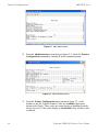
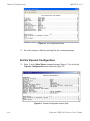
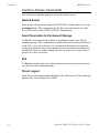
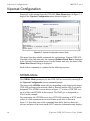
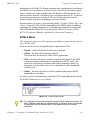
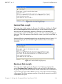
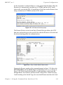
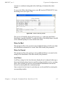
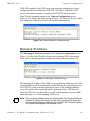
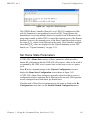
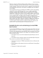
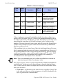
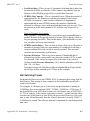
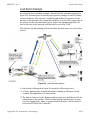
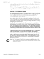
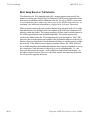
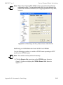
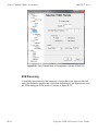
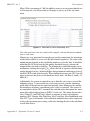
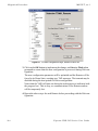
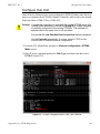
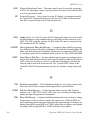
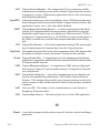
M en u D e sc r i p t i o n s
MN/22137, rev 1
Figure 3-5 FAST Feature Code dialog
Tip: Contact either the network administrator or Comtech Vipersat Networks
Customer Support to obtain the Feature codes. A convenient option is to
use the Vipersat Vload utility to manage Feature codes.
Vipersat Management
This item is an information-only display, and indicates whether Vipersat
Management is Enabled or Disabled in the target CDD-56X. Activation of the
Vipersat Feature Code automatically enables the Vipersat Management feature.
Caution: This command must be Enabled in order to utilize any of the Vipersat
capabilities of the CDD-56X.
Vipersat STDMA
In order to utilize the Vipersat STDMA feature (burst mode) in the target
Vipersat CDD-56X, this feature must be Enabled. Enter A at the command
prompt to toggle On or Off.
Refer to table 2-2 for the relationship between Unit Role and STDMA. This
feature should only be enabled for a unit that is used as a Hub with no expansion
(i.e., a Burst Controller).
NOTE
Note: Although the CDD-56X has multiple demods, STDMA is configurable for
only one demod. When this parameter is enabled, Demod 1 is set for
STDMA mode and the remaining demods are set for SCPC mode.
Vipersat Auto Switching
The Vipersat Auto Switching feature allows the CDD-56X to automatically
adjust to varying bandwidth demands in the Vipersat network by switching
between STDMA and SCPC connections. This feature should only be enabled
for a unit that is used as a Hub with no expansion, and that will be required to
send switching requests to the VMS in response to either traffic type (Application switching) or network traffic loads (Load switching). Refer to table 2-2 for
the relationship between Unit Role and Auto Switching.
3-6
Vipersat CDD-56X Series User Guide
MN/22137, rev 1
M e n u D e sc r i p t i o n s
To activate the Vipersat Auto Switching capabilities of the target CDD-56X,
toggle the Auto Switching command to Enabled by entering W at the command
prompt.
See the section “STDMA/SCPC Automatic Switching” on page 3-32 for more
details on the use of this feature. For additional information, refer to Appendix
B, “Automatic Switching”.
Vipersat File Streamer
Vipersat File Streamer (VFS) is an optional feature that allows rapid file transfers over the satellite network between host PCs that are running the client VFS
application. To activate the Vipersat File Streaming capabilities of the
CDD-56X, toggle this command to Enabled by entering R at the command
prompt.
Once the parameters on the Feature Configuration screen have been set as
desired, return to the Main Menu and enter the V command to display the
Vipersat Configuration screen shown in figure 3-6.
C h ap t e r 3 - U s i n g t h e C o m m a n d L in e I n t e r f a c e ( C L I )
3-7
V i p er s a t C o nf i g u r at i o n
MN/22137, rev 1
Vipersat Configuration
Entering V at the prompt from the CDD-56X Main Menu shown in figure 3-1
displays the Vipersat Configuration menu shown in figure 3-6.
Figure 3-6 Vipersat Configuration screen (Hub)
This menu lists the available commands for configuring a Vipersat CDD-56X.
Note that for the Hub unit only, the command Primary Heart Beat is displayed
in the Vipersat Configuration screen. For the Remote unit only, the status of the
Home State Revert setting is displayed.
Each of these commands is explained in the following sections.
STDMA Mode
The STDMA Mode parameters for this CDD-56X are accessed by entering T at
the Vipersat Configuration screen command prompt.
The items in the STDMA menu will vary depending on the function the target
CDD-56X performs in the network (Hub or Remote) and the Hub Type that is
designated. The STDMA screen shown in figure 3-7 is from a CDD-56X serving as a Hub with STDMA in the network. The Hub Type is designated as
Fixed, in this example.
For comparison, the STDMA screen for a CDD-56X operating in SCPC mode
(either as a Hub expansion unit or as a Remote mesh unit) is shown in
figure 3-8. Note that some of the command items differ between these two
screens, and most of the items on the SCPC menu are information-only display..
3-8
Vipersat CDD-56X Series User Guide
MN/22137, rev 1
V i p er s at C o n f i g u r a t io n
Figure 3-7 STDMA screen (Hub, STDMA, Fixed type)
Figure 3-8 STDMA screen (Hub/Remote, SCPC)
STDMA
This menu item is read-only and shows the current state of STDMA in the
CDD-56X. In order to change the STDMA state, refer to the section “Feature
Configuration” on page 3-5.
C h ap t e r 3 - U s i n g t h e C o m m a n d L in e I n t e r f a c e ( C L I )
3-9
V i p er s a t C o nf i g u r at i o n
MN/22137, rev 1
STDMA Tx Rate
This menu item shows the STDMA Transmit Rate (in bps) of data that the
CDD-56X receives. This item is read-only and cannot be modified in this menu.
Hub Type
This menu item is only displayed if the CDD-56X is being used as a Hub in the
network, and provides the functionality for the STDMA Burst Controller.
Vipersat STDMA has six modes of operation:
• Fixed — all remotes get the same data slot time (slot size) in the cycle,
regardless of activity. Cycle time is fixed also.
• Dynamic Slot — data slot time of remotes vary according to activity,
cycle time does not.
• Dynamic Cycle — slot time and cycle time vary according to activity of
remotes.
• GIR (Guaranteed Information Rate) — each remote always has at least the
minimum data slot size when needed, and cycle time is variable up to a
maximum of one second.
• Entry Channel — remotes run in SCPC mode, but STDMA is used for
maintenance and control channel.
• ECMv2 — utilizes a modified slotted Aloha method for remotes to
establish registration in the network and obtain the means for switching
into SCPC mode.
The Hub can be configured to operate as one of the six types by entering a T at
the command prompt to display the dialog shown in figure 3-9.
Figure 3-9 Hub Type prompt
This selection determines whether available bandwidth will be a static (fixed)
assignment, or whether bandwidth allocation will be dynamic with automatic
switching to dynamically optimize bandwidth utilization.
3-10
Vipersat CDD-56X Series User Guide
MN/22137, rev 1
V i p er s at C o n f i g u r a t io n
Refer to Appendix B, “Automatic Switching”, for additional information on
how each of the bandwidth allocation modes functions and the parameters used
to calculate the commands for each mode.
1 – Fixed
In the Fixed mode, all remotes have the same data slot size regardless of type of
traffic or load. This mode minimizes the amount of jitter between remote transmission times, and is useful for tuning STDMA as well as for troubleshooting
purposes.
2 – Dynamic Slot
In the Dynamic Slot mode, slot size is adjusted each cycle depending on the
activity during the previous cycle. The slot size for each remote is computed
based on the time (at the current data rate) needed to transmit all the bytes in
queue. If the result is less than the minimum slot size or more than the maximum slot size, the slot is adjusted accordingly. This mode allows the burst
controller to provide additional slot time in the cycle to remotes with higher
traffic demands, and helps to alleviate congestion.
3 – Dynamic Cycle
In the Dynamic Cycle mode, available bandwidth is allocated to remotes
proportionally based on their current bandwidth needs. The bandwidth requirements are determined by the number of bytes in queue for each remote divided
by the total number of bytes in queue for all remotes, and results in the percentage of bandwidth to allocate for each remote. This mode provides improved
efficiency of STDMA due to faster cycle times during periods of light traffic
demands, thus providing minimum latency for the current load.
4 – GIR
In the GIR mode, the initial computed slot size value is the same as in the
Dynamic Cycle mode except there is no maximum limit. After all remotes have
been assigned slots, the burst map is checked to see if the total cycle length
exceeds one second. If not, then all requirements are satisfied and the burst map
is complete. However, if the cycle is greater than one second, then the slots are
adjusted proportionally so that all remotes receive at least their guaranteed rate
plus whatever excess is still available.
GIR mode allows guaranteed information rates to be set for each remote in the
group. When the one second restriction is exceeded, remotes without a specified
GIR are reduced to the global minimum slot size and the remaining bandwidth
is distributed to remotes that have been assigned a GIR rate, thus ensuring additional bandwidth to these units when needed.
C h ap t e r 3 - U s i n g t h e C o m m a n d L in e I n t e r f a c e ( C L I )
3-11
V i p er s a t C o nf i g u r at i o n
NOTE
MN/22137, rev 1
Note: GIR allocations are restricted so that assigned GIR totals cannot exceed
the available bandwidth. This ensures proper bandwidth allocation when
the network is overloaded.
The GIR setting for each Remote is specified using the STDMA Remote Policies screen (refer to the section “Set Remote Policies” on page 3-24). When
combined with Auto switching, GIR allows trigger points to be set where the
Remote will jump out into SCPC mode. This is done using the Load Switch
setting. Note that, for this function, Auto switching must be Enabled on this
Hub unit, and corresponding Remote modems must be configured with Auto
switching and Load switching Enabled. Also, the settings for Step Up and Step
Down Threshold values should be adjusted as necessary for the application.
5 – Entry Channel
The Entry Channel mode provides remotes in the group with a shared channel
in which they can gain initial access to the network. Since very small STDMA
data rates are required in this configuration, a larger number of remotes can
share the cycle. As soon as the Hub receives an STDMA ACK from the
Remote, it initiates an immediate switch to SCPC mode based on the policy set
for that Remote. Note that the switch occurs as soon as the Hub receives an
ACK even though there may not be traffic at that time. The persistence of the
link will be determined by the unit’s flag settings.
When choosing Entry Channel as the Hub type for the STDMA Controller, the
Auto switching feature must be Enabled on this Hub unit, and switching policies
for the remotes must be configured (refer to the section “Set Remote Policies”
on page 3-24). Corresponding Remote modems must be configured with Auto
switching and Load switching Enabled. Note that the settings for Step Up and
Step Down Threshold values should be adjusted as necessary for the application.
This mode is designed to accommodate the needs of a Remote that will not be
continuously connected to the network, but which has the need to be able to
make an on-demand connection when required, such as in a mobile application.
In the event of a power outage, Entry Channel provides a bandwidth-efficient
method for remotes with low latency requirements to re-enter the network once
power is restored.
6 – ECMv2
The ECMv2 (Dynamic Entry Channel) mode is very similar to the regular
Entry Channel mode. However, the associated limitation in the number of
Remotes is eliminated via the modified slotted Aloha method that is utilized for
this mode. No cycle is used, and a Remote List is not necessary.
The Hub broadcasts an anouncement message to all Remotes that are tuned to
receive it that provides the available slots and the tuning parameters for trans3-12
Vipersat CDD-56X Series User Guide
MN/22137, rev 1
V i p er s at C o n f i g u r a t io n
mitting back to the Hub. The Remotes transmit on a contention basis and should
a collision occur, the Remote will back off for a specified period and try again.
Once it obtains one of the available slots, the Remote will hold onto the slot
until it registers with the VMS and receives assignment into dSCPC, or until all
necessary transactions are completed. The slot is then released for use by
another Remote unit that is attempting to enter the channel.
Remotes can be set to one of four operating modes—Disable, Offline, Wait, and
Online—from the ECMv2 Mode command in the STDMA menu. In addition,
commands for setting parameters to accomodate any mismatches between the
Hub LNB and the Remote BUCs are presented: LNB LO Frequency (Hub),
BUC LO Frequency (Remote), and Satellite Conversion Frequency.
ECMv2 Mode
This menu item appears for Hub expansion and Remote expansion units operating in ECMv2 only.
Each unit can be set to a designated mode of operation in ECM:
• Disable – the ECM function for this unit is disabled.
• Offline – the unit will not transmit (muted).
This mode may be chosen for radio silence applications.
• Wait – the unit will register with the controller and remain in the ECM
wait queue without assignment for switching into dSCPC mode. This
mode may be chosen by operators who wish to manually control (via
diagnostic switch) when a unit is to be switched and utilize bandwidth
from the pool.
• Online – the unit will register with the controller and request dSCPC
bandwidth for switching.
In order for a unit to automatically switch into SCPC mode and pass data traffic,
the ECMv2 Mode must be set to Online.
Figure 3-10 ECMv2 Mode prompt
Tip: For purposes of commissioning the terminal with a continuous carrier, the
Entry Channel mode can be set temporarily to Disable. Once this process
is completed, set the Remote back to the desired mode for normal
operation.
C h ap t e r 3 - U s i n g t h e C o m m a n d L in e I n t e r f a c e ( C L I )
3-13
V i p er s a t C o nf i g u r at i o n
MN/22137, rev 1
Group ID
The STDMA Group ID number defines a group of equipment (including
CDD-56X Hub and Remote units) that will respond to the output of a single
STDMA burst controller. This group is addressable within a network which, in
turn, is defined by the Network ID number assigned to the CDD-56X.
Allocation of bandwidth is shared among the remotes in an STDMA group.
Depending on the number of remotes in a network, a Hub may have multiple
burst controllers, each with its own set of remotes. This is accomplished by
assigning a unique Group ID number to each controller and its associated
remotes.
NOTE
Note: The STDMA Group ID number and the Network ID number are independent. There can be multiple STDMA groups within a single network.
The target CDD-56X Group ID can be modified by entering an I at the
command prompt to display the dialog shown in figure 3-11.
Figure 3-11 Group ID prompt
STDMA Max Power Hunt
This menu item appears for Remote modems only.
Should link reception from a Remote be incorrect or impaired (e.g., poor environmental conditions), the STDMA Max Power Hunt feature is an option on
the Remote modem that automatically adjusts the Remote transmit power to
ensure that burst map acknowledgements from that unit are received by the Hub
burst controller. When enabled, the burst controller sets a flag in the burst map
that indicates it is not receiving acknowledgements from an enabled Remote.
When the Remote receives the burst map, it will see the flag and automatically
increase power up to the maximum value specified with this parameter (3, 6, or
9 dB) above the default or Home State setting. If this closes the link, the burst
controller will clear the flag. Note that if the dB increase is more than is necessary, DPC will make a down adjustment to the appropriate level and this adjustment will be added to the DPC Offset.
3-14
Vipersat CDD-56X Series User Guide
MN/22137, rev 1
V i p er s at C o n f i g u r a t io n
This feature option is Enabled/Disabled by entering H at the command prompt.
Figure 3-12 STDMA Max Power Hunt prompt
Low Data Rate Fast Acquisition
Configurable on a Hub Burst Controller only.
This menu item is a toggle used to Enable or Disable the Vipersat Burst Fast
Acquisition Timing (BFAT) feature that functions at low data rates (64 kbps to
256 kbps). This feature allows for significantly faster acquisition times at these
data rates, even with higher noise, resulting in improved efficiency of the shared
STDMA channel. Since signal lock is faster at higher data rates, BFAT is not
active above 256 kbps.
Entering A at the command prompt will toggle this feature On or Off.
This feature requires Router firmware version 1.5.3 or later. The unit configuration must be set for operation at either 3/4 QPSK or .95 QPSK in order to utilize
BFAT.
NOTE
Note: Use of BFAT is NOT recommended with ECMv2.
When this feature is enabled with any other STDMA allocation method,
the Preamble parameter becomes fixed (not settable by the user) and
this value is automatically determined by the system—appears as
display only in the CLI; not displayed in the Parameter Editor.
Burstmap Multicast IP
This menu item is used to define the IP address for the Burstmap Multicast that
is sent out by the STDMA burst controller at the Hub to all of the associated
remotes in that group. This address must be the same for all members of the
goup. The burstmap is a proprietary message sent from the Hub to all remotes,
at regular intervals, specifying the relative start time and duration for each
terminal to transmit.
To change the current address, enter N at the command prompt to display the
dialog shown in figure 3-13.
C h ap t e r 3 - U s i n g t h e C o m m a n d L in e I n t e r f a c e ( C L I )
3-15
V i p er s a t C o nf i g u r at i o n
MN/22137, rev 1
Figure 3-13 Burstmap Multicast IP prompt
Outbound IP
This menu item, which appears for all Hub configurations, displays the current
Outbound IP address. This specifies the Hub device that is supplying the TDM
outbound to the satellite (typically a CDM-570L). Specifying this address is
necessary for Hub configurations that utilize a burst controller (such as the
CDD-56X) that is a separate device from the TDM modem.
This address must also be defined when using the following features:
• DPC
• SOTM
The Outbound IP address will be the same as the burst controller IP address
when the burst controller and the TDM modem are the same device.
To define the TDM outbound address, enter O at the command prompt to
display the dialog shown in figure 3-14.
Figure 3-14 Outbound IP prompt
Cycles Per Burst Map
This menu item, which appears for Hub types Fixed, Dynamic Slot, and Entry
Channel, displays the number of spin cycles that will occur prior to each broadcast of the Burst Map by the burst controller to the remotes. One cycle is the
amount of time it takes for all remotes in a group to burst on the common channel. The burst map provides each remote with its allocated bandwidth and position in the cycle.
3-16
Vipersat CDD-56X Series User Guide
MN/22137, rev 1
V i p er s at C o n f i g u r a t io n
For Dynamic Cycle and GIR configurations, the number of cycles is automatically set to one in order to ensure optimum performance for these Hub types.
This parameter can be modified by entering a C at the command prompt to
display the dialog shown in figure 3-15.
Figure 3-15 Cycles per Burst Map prompt
Slot Guardband
This menu item, which appears for all Hub configurations, displays the current
length of the Slot Guardband in milliseconds and in bytes for the remotes in the
group. The Slot Guardband is the amount of time between the point when one
remote completes transmitting data and the point when the next remote in the
cycle begins transmitting. This prevents the remote from overrunning the next
terminal in the cycle. The setting for this parameter should be obtained using the
Vipersat STDMA calculator.
Tip: For a copy of the latest Viper Calculator, contact a Comtech Vipersat
Networks representative.
This value can be modified by entering a G at the command prompt to display
the dialog shown in figure 3-16 and entering a new value.
Figure 3-16 Slot Guardband prompt
NOTE
Note: The value entered at the command line in figure 3-16 is in milliseconds.
The corresponding value expressed in bytes is calculated by the
C h ap t e r 3 - U s i n g t h e C o m m a n d L in e I n t e r f a c e ( C L I )
3-17
V i p er s a t C o nf i g u r at i o n
MN/22137, rev 1
CDD-56X based on the STDMA transmit bit rate as shown in the menu
in figure 3-7.
Slot Preamble Length
This menu item, which appears in all Hub and Remote configurations, displays
the current Slot Preamble size in milliseconds and bytes for the remotes in the
group. The Slot Preamble is the period between when the remote begins to
transmit (sends an ACK) to the Hub and when the first data packet is sent. This
allows time for signal lock to occur before data is sent, thus preventing data
loss. Higher data rates allow for a shorter preamble, since it is easier to achieve
signal lock. The setting for this parameter should be obtained using the Vipersat
STDMA Calculator.
Tip: For a copy of the latest Viper Calculator, contact a Comtech Vipersat
Networks representative.
NOTE
Note: When either the BFAT feature is enabled or the Hub Type is ECMv2, the
preamble length is set automatically for the unit.
On a Hub unit, entering a P at the command prompt allows changing the preamble duration in milliseconds.
Figure 3-17 Slot Preamble Length prompt
Slot Data Length
This menu item, which appears for Fixed, Entry Channel, and ECMv2 Hub
types, displays the current Slot Data Length in milliseconds and bytes for the
remotes in the group, and represents the amount of data that can be transmitted
or received in one spin of the STDMA cycle by each of the remotes belonging
to that group. This is the amount of time that the remote is provided to send data
in the cycle.
To change this setting, enter B at the command prompt to display the dialog
shown in figure 3-18.
3-18
Vipersat CDD-56X Series User Guide
MN/22137, rev 1
V i p er s at C o n f i g u r a t io n
Figure 3-18 Slot Data Length prompt
Nominal Data Length
This menu item, which appears for Dynamic Slot Hub type, displays the Nominal slot Data Length in milliseconds and bytes for the remotes in the group,
and represents the approximate amount of data that can be transmitted or
received in one spin of the STDMA cycle by each of the remotes belonging to
that group. This is the amount of time that the remote is provided to send data in
the cycle.
Entering a B at the command prompt brings up the dialog shown in figure 3-19
allowing changing the nominal data length, in milliseconds, for the target
CDD-56X.
Figure 3-19 Nominal Data Length prompt
Maximum Data Length
This menu item, which appears for Dynamic Cycle Hub type, displays the
current Maximum Data Length in milliseconds and bytes for the remotes in
the group, and represents the maximum amount of data that can be transmitted
or received in one spin of the STDMA cycle by each of the remotes belonging
to that group. This is the maximum amount of time that the remote is provided
to send data in the cycle.
C h ap t e r 3 - U s i n g t h e C o m m a n d L in e I n t e r f a c e ( C L I )
3-19
V i p er s a t C o nf i g u r at i o n
MN/22137, rev 1
To change this setting, enter B at the command prompt to display the dialog
shown in figure 3-20.
Figure 3-20 Maximum Data Length prompt
Minimum Data Length
This menu item, which appears for Dynamic Slot, Dynamic Cycle, GIR, and
Entry Channel Hub types, displays the current Minimum Data Length in milliseconds and bytes for the remotes in the group, and represents the minimum
amount of data that can be transmitted or received in one spin of the STDMA
cycle by each of the remotes belonging to that group. This is the minimum
amount of time that the remote is provided to send data in the cycle.
Entering an M at the command prompt brings up the dialog shown in
figure 3-21 allowing the minimum data length, in milliseconds, to be changed
for the target CDD-56X.
Figure 3-21 Minimum Data Length prompt
Total Slot Count
This menu item appears for Hub units operating in ECMv2 only.
3-20
Vipersat CDD-56X Series User Guide
MN/22137, rev 1
V i p er s at C o n f i g u r a t io n
This parameter defines the number of time slots per cycle available for assignment to the Remotes in queue that are to be switched from ECM into dSCPC.
These are the Remotes that are tagged for Online mode. By design, ECM works
on a contention basis, with the number of slots being some fraction of the total
number of Remotes. In order for this ratio to be optimized, a Vipersat calculator
is available to determine this setting.
Tip: Contact a Comtech Vipersat Networks representative for a copy of the
latest Vipersat ECM Calculator.
Entering R at the command prompt allows changing the slot count.
Valid range is 1 to 255.
Figure 3-22 Total Slot Count prompt
Slot Cycle Length
This menu item is for information only and displays the Slot Cycle Length in
milliseconds and bytes for the remotes in the group. This value represents the
total amount of time—preamble, data length, and guardband—allocated to the
Remote terminal during one spin cycle.
Slot Start in Cycle
This menu item appears in the STDMA screen when the Unit Role is Remote;
however, it is not relevant since a Remote configuration does not enable
STDMA.
Set Remotes
This menu item appears in the STDMA screen when the Unit Role is Hub with
No Expansion, except for Hub Type ECMv2.
Entering an R at the command prompt displays the STDMA Remotes Menu as
shown in figure 3-23. This screen is used to define and make modifications to
the Remotes that belong to the STDMA group for the Hub burst controller, as
well as to display the burst map status information for each Remote.
C h ap t e r 3 - U s i n g t h e C o m m a n d L in e I n t e r f a c e ( C L I )
3-21
V i p er s a t C o nf i g u r at i o n
MN/22137, rev 1
Figure 3-23 STDMA Remotes Menu screen
Adding a Remote to the STDMA Group
Entering the item number for the Remote demodulator/router brings up the
dialog shown in figure 3-24. A prompt to enter the Name to assign to the
Remote unit appears, followed by a prompt to enter the IP Address for this unit.
Figure 3-24 Remote Name and IP Address prompt
Once a Remote has been added to the group, its Status in the group is displayed
by the use of the following letters:
• U = Used – This Remote is being used in the burstmap.
Once a remote has been added to the STDMA group, this status will
always be displayed.
• B = Burstmap – This Remote is currently in the burstmap.
This status will be displayed unless the remote has been removed (R),
disabled (D), or switched (S) out of the STDMA burstmap.
3-22
Vipersat CDD-56X Series User Guide
MN/22137, rev 1
V i p er s at C o n f i g u r a t io n
• R = Removed – This Remote is currently removed from the burstmap.
When displayed, this status indicates that the Hub has removed this remote
from the burstmap due to a communications fault.
• D = Disabled – This Remote is currently disabled and is not in the
burstmap.
This status will be displayed when a remote is manually disabled by the
operator or administrator.
• S = Switched – This Remote is currently switched into SCPC mode.
When displayed, this status indicates that the VMS has automatically
switched the remote out of the burstmap and into SCPC operation.
• H = Home State Revert – This Remote is not currently receiving burst
maps. When a remote, stuck in SCPC mode by failure to receive a VMS
revert command, sees the burst map with this flag set, it will automatically
revert to its home state and STDMA mode.
• CF – This Remote has not sent an acknowledgement to the burst controller
since it was enabled.
Most commonly, either a B or an S will be displayed, as a typical Remote
will be either Bursting or Switched out to the dSCPC pool.
Base
Entering a B at the command prompt in figure 3-23 allows entering the Remote
number to start displaying remotes in this menu screen. Entering the number 1,
as shown in figure 3-23, displays nine remotes, 1 through 9. If the number 4 had
been entered, the display would show the nine remotes starting with Remote 4
(i.e., remotes 4 through 12).
Figure 3-25 Base Remote Display prompt
Remote Count
The Remote Count menu item in figure 3-23 is an information-only display
showing the total number of Remotes that currently belong to the STDMA
group for this Hub burst controller.
C h ap t e r 3 - U s i n g t h e C o m m a n d L in e I n t e r f a c e ( C L I )
3-23
V i p er s a t C o nf i g u r at i o n
MN/22137, rev 1
Set Remote Policies
This menu item, which appears for GIR and Entry Channel Hub types, allows
each Remote to be configured for specific data switching conditions.
For Hub STDMA Controllers operating in either GIR or Entry Channel mode,
typical load switching is not the mechanism that performs the transition from
STDMA to SCPC mode due to traffic load. In GIR mode, the Remote is
switched to SCPC as soon as the GIR threshold is reached. In Entry Channel
mode, the Remote is switched to SCPC as soon as the Hub receives the first
transmission from the Remote.
For both GIR and ECM, the event of switching from STDMA to SCPC can only
occur if the SCPC Switch Rate parameter is set to a value greater than 0 (zero).
If the switch rate for a Remote is set to 0 kbps, that Remote will remain in
STDMA mode and will only switch to SCPC mode due to an application switch
or a diagnostic (manual) switch.
Entering P at the STDMA Remotes Menu command prompt displays the
Remote Policies screens shown in figure 3-26 (GIR Hub) and figure 3-28
(Entry Channel Hub).
Figure 3-26 STDMA Remote Policies screen (GIR Hub)
Entering the Remote number at the command prompt in figure 3-26 allows the
Guaranteed Information Rate and the Automatic Load Switch Rate for that
Remote to be set, as shown in figure 3-27. Note that the Available Bandwidth is
displayed for reference in this screen to assist with entering the appropriate
rates. The cycle length for GIR is limited to a maximum of one second.
3-24
Vipersat CDD-56X Series User Guide
MN/22137, rev 1
V i p er s at C o n f i g u r a t io n
Set the Automatic Load Switch Rate to a value greater than the GIR to allow the
Remote to be automatically switched out of STDMA and into SCPC mode
when traffic exceeds the GIR. A Switch Rate of 0 will prevent the Remote from
being switched out of STDMA and into SCPC mode.
Figure 3-27 GIR Remote Policies prompt
The Remote Policies screen for an Entry Channel Hub type allows the SCPC
data rates and switch types to be specified for when the Remotes will switch and
the desired starting points for communications.
Figure 3-28 Entry Channel Switch Rates screen
Entering the Remote number at the command prompt in figure 3-28 allows the
SCPC Data Rate and the Switch Type for that Remote to be set, as shown in
figure 3-29. Switch type 0 corresponds to Load Switching; switch types 64
through 255 are user-defined, and must match VMS policies. When choosing
Load Switching as the Switch Type, the associated Remote must have the Load
C h ap t e r 3 - U s i n g t h e C o m m a n d L in e I n t e r f a c e ( C L I )
3-25
V i p er s a t C o nf i g u r at i o n
MN/22137, rev 1
Switching feature Enabled (see the section “STDMA/SCPC Automatic Switching” on page 3-32).
Figure 3-29 Remote SCPC Data Rate prompt
The Global SCPC Rate command can be used to set the data rate for all or a
majority of the Remotes. This allows the rate to be entered just once instead of
entering the rate for each Remote individually. Enter G at the command prompt
in figure 3-28.
Figure 3-30 Global SCPC Data Rate prompt
Similarly, the Global Switch Type command can be used to set the switch type
for all or a majority of the Remotes. Enter H at the command prompt.
Figure 3-31 Global Switch Type prompt
Delete Remote
Entering D at the command prompt shown in figure 3-23 brings up the Delete
Remote dialog shown in figure 3-32.
3-26
Vipersat CDD-56X Series User Guide
MN/22137, rev 1
V i p er s at C o n f i g u r a t io n
Figure 3-32 Delete Remote prompt
Enter the number of the Remote CDD-56X at the command prompt to delete it
from the STDMA group for this Hub burst controller.
Enable/Disable Remote
Enter E at the command prompt in figure 3-23 to display the dialog shown in
figure 3-33. The Remotes in the network are displayed, indicating whether each
is currently Enabled (E) or Disabled.
Figure 3-33 Enable/Disable Remote prompt
Enter the number of the Remote at the command prompt to toggle the Remote
from its current Enable/Disable configuration.
In the example screen shown above, both Remotes 1 and 2 are Enabled.
View Remote(s)
Entering V at the command prompt shown in figure 3-23 will display the listing
of Remote(s) that belong to the STDMA group for this Hub burst controller, and
their status, as shown in figure 3-34.
Figure 3-34 View Remote(s) screen
C h ap t e r 3 - U s i n g t h e C o m m a n d L in e I n t e r f a c e ( C L I )
3-27
V i p er s a t C o nf i g u r at i o n
MN/22137, rev 1
The display is for information only and pressing any key will return the screen
to the menu shown in figure 3-23.
Remove Timeout
Entering R at the command prompt shown in figure 3-23 will display the
Remove Timeout dialog shown in figure 3-35. Note that this menu item shows
the current setting (in seconds) for this parameter.
Figure 3-35 Remove Timeout prompt
The value entered at the command prompt defines the amount of time (in
seconds) with no communication from a Remote to the Hub before that Remote
is removed from the Burst Map. If communications are lost for this specified
period of time, the Remote is removed from the STDMA group, and the bandwidth resources it had been allocated are then made available for use by the
other remotes remaining in the group.
This feature is useful, for example, in an SNG application where a mobile
Remote has finished its assignment and has shut down.
Remove Retry Timeout
Entering T at the command prompt in figure 3-23 will display the Remove
Retry Timeout dialog shown in figure 3-36. Note that this menu item shows
the current setting (in seconds) for this parameter.
Figure 3-36 Remove Retry Timeout prompt
3-28
Vipersat CDD-56X Series User Guide
MN/22137, rev 1
V i p er s at C o n f i g u r a t io n
When a Remote is removed from the group Burst Map, as described in the
section “Remove Timeout” above, entering a value in the Remove Retry Timeout dialog defines the amount of time (in seconds) that is allowed to pass before
a retry attempt is made to return the removed Remote to the group. The Remote
is re-entered into the burst map cycle; if the Remote does not burst back (ACK)
to the Hub burst controller, it is again removed from the Burst Map.
This allows, again using a mobile Remote as an example, shutting down the
Remote at one location, moving it to a new location, and then automatically reestablishing a connection to the satellite network.
LNB LO Frequency
This menu item appears for an ECMv2 Hub type only.
This parameter, together with the Satellite Frequency Conversion setting, is critical for determining RF frequency translations between Hub and Remote offsets
or data spectral inversions. Take care in setting these correctly.
Enter Z at the command prompt and specify the correct LNB Local Oscillator
frequency (MHz) that this Hub unit will be receiving.
Figure 3-37 LNB LO Frequency prompt
Satellite Frequency Conversion
This menu item appears for the ECMv2 Hub type only.
This parameter, together with the LNB LO Frequency setting, is critical for
determining RF frequency translations between Hub and Remote offsets or data
spectral inversions. Take care in setting these correctly.
Enter F at the command prompt and specify the correct Satellite Frequency
Conversion value (MHz) that this Hub unit requires.
Figure 3-38 Satellite Frequency Conversion prompt
C h ap t e r 3 - U s i n g t h e C o m m a n d L in e I n t e r f a c e ( C L I )
3-29
V i p er s a t C o nf i g u r at i o n
MN/22137, rev 1
STDMA Statistics
Entering V at the command prompt in the STDMA screen displays the STDMA
Statistics screen as shown in either figure 3-39 (Hub) or figure 3-40 (Remote).
Note that statistics will only be accumulated for a CDD-56X that is configured
as a Hub with No Expansion, since that is the only configuration that provides
STDMA functionality (on Demod 1). Because a Remote unit is SCPC mode
only, the STDMA Statistics screen will display all values as 0.
Figure 3-39 STDMA Statistics screen (Hub)
Figure 3-40 STDMA Statistics screen (Remote)
Stats Accumulation Window
Entering W at the command prompt displays the Stats Accumulation Window
as shown in figure 3-41. The time period, in seconds, for capturing STDMA
statistics can be specified.
3-30
Vipersat CDD-56X Series User Guide
MN/22137, rev 1
V i p er s at C o n f i g u r a t io n
Figure 3-41 Stats Accumulation Window prompt
Clear
The STDMA statistics can be Cleared (reset) by entering a C at the command
prompt in figure 3-39.
Show Hub Statistics
Entering a W at the command prompt in the STDMA screen displays the
current statistics for the target CDD-56X Hub as shown in figure 3-42.
Figure 3-42 Show Hub Statistics screen
Statistics in the received ACK from each Remote are monitored by the Burst
Controller. These statistics report the fill status of the burst data slot for each
Remote. The Burst Controller builds a table of the group and calculates the relative data byte count for each Remote. It then calculates the length of the Data
Slot for each Remote based on the Minimum Slot Length plus a percentage of
the Available Bandwidth. Idle Remotes receive a data slot equal to the Minimum Slot Length.
In figure 3-42, Remote 1 with IP address 10.1.128.1 had activity during the
averaging period. It captured 37.8% of the total slot time and had an average
slot length of 283 ms. Remotes 2, 3, and 4 had 41.5%, 18.1% and 7.6% respectively. The dynamic range of STDMA is a function of the difference between
the Nominal Data Length and the Minimum Data Length parameters. These
C h ap t e r 3 - U s i n g t h e C o m m a n d L in e I n t e r f a c e ( C L I )
3-31
V i p er s a t C o nf i g u r at i o n
MN/22137, rev 1
parameters are operator selectable. The speed with which STDMA reacts to
changes in dynamic load is a function of the Statistics Accumulation Window
parameter and the Cycles per New Burst Map parameter, both of which are also
operator selectable.
The Hub statistics are useful for tuning the Burst Controller. Preamble adjustments, up or down, are made using the missed ACKs statistic; a preamble and/
or guardband that is too short will result in an accumulation of missed ACKs.
The “Cont” column represents continuous—the number of sequential ACKs
missed.
An informative indicator in the Hub Statistics screen is the STDMA status of
the Remotes that appears in the first column to the right of the IP Address list.
The Remote status is displayed in one of three possible modes:
• E – Remote is Enabled and active in the STDMA group; the Hub burst
controller is receiving ACKs from this Remote.
• ER – Remote is Enabled but has been Removed from the STDMA group
due to missed ACKs at the Hub burst controller.
• (Blank) – Remote either has been manually Disabled, such as through the
STDMA Remotes Menu Enable/Disable command, or has been switched
out of STDMA to SCPC mode by the VMS.
STDMA/SCPC Automatic Switching
One of the most powerful features of the Vipersat Network system is the capability to perform Automatic switching between STDMA mode and SCPC mode
based on bandwidth demand. The configuration options that are available to
meet customer-specific requirements are extensive, and include switching based
on Load, Application (Voice and Video RTP), ToS, and QoS.
For additional information, refer to Appendix B, “Automatic Switching”, in this
document.
NOTE
Note: Care must be taken when configuring the Auto Switching features of the
Vipersat system to ensure that there is no duplication or overlap of
switching functions between Application, ToS, and QoS for a particular
traffic flow. Only one of these switching methods should be utilized for
any one flow requirement.
Automatic Switching for the CDD-56X is an option that is available only when
configured as an STDMA Hub unit (burst controller). Note that Automatic
switching does not apply to either a Hub Expansion unit or a Remote Expansion
unit; these Vipersat working modes operate in dedicated SCPC mode and all
3-32
Vipersat CDD-56X Series User Guide
MN/22137, rev 1
V i p er s at C o n f i g u r a t io n
switching control is performed by the VMS. As is shown in table 2-2, Auto
Switching should be Disabled for these two modes.
The Auto Switching feature must be Enabled (as described in the section
“Feature Configuration” on page 3-5) in order to allow any associated Remote
modems to perform STDMA/SCPC switching. In order for a Remote modem in
the group to be automatically switched between STDMA and SCPC modes, the
Auto Switching feature of that Remote must be Enabled as well.
Selecting Automatic Switching from the Vipersat Configuration menu
shown in figure 3-6 (enter A) for a CDD-56X operating as a network Hub will
display the menu shown in figure 3-43.
Figure 3-43 Automatic Switching screen
The following sections describe the menu items of the STDMA/SCPC Auto
Switching screen shown in figure 3-43.
Auto Switching
The Auto Switching item on the menu shown in figure 3-43 is for information
only and shows the current configuration of the Hub CDD-56X. This feature is
Enabled and Disabled as described in the section “Feature Configuration” on
page 3-5. Auto Switching must be Enabled in order to utilize any of the related
features/commands in this menu.
Note that Auto Switching must be Enabled on a Hub STDMA Controller that is
configured for either Entry Channel or ECMv2 mode.
C h ap t e r 3 - U s i n g t h e C o m m a n d L in e I n t e r f a c e ( C L I )
3-33
V i p er s a t C o nf i g u r at i o n
MN/22137, rev 1
Current WAN Transmit Mode
The Current WAN Transmit Mode item on the menu in figure 3-43 is information only and reflects the current transmit status of a unit. In the case of the
CDD-56X, there is no transmit function (no modulator) and this parameter is
not applicable.
Load Switching
The Load Switching command on the menu in figure 3-43 is a toggle Enabling
and Disabling Load Switching on the target Hub CDD-56X. The system will
detect variations in data rate and can be configured to switch from STDMA to
SCPC based on bandwidth requirements.
The initial switch for a Remote Vipersat terminal from STDMA mode to SCPC
mode is determined by the Hub Burst Controller. Once the Remote is switched
into SCPC, any requests to meet additional switching requirements within
SCPC (Step Up or Step Down) are made by the Remote modem.
Entering a B at the command prompt will toggle this feature On or Off for the
target CDD-56X.
NOTE
Note: Load switching must be Enabled for any Hub CDD-56X burst controller
that will experience changing load conditions in order for the VMS to
dynamically optimize network performance on these circuits.
Application switching by the VMS (Voice and/or Video) is not affected by
this setting. However, using Load switching for real-time applications is
not recommended.
STDMA Slot Capacity
The STDMA Slot Capacity command, shown in figure 3-43, allows setting the
threshold or level of slot capacity at which the Burst Controller sends a switch
request to the VMS to switch the Remote from STDMA mode to SCPC mode.
Enter U at the command prompt to display the dialog shown in figure 3-44.
Figure 3-44 STDMA Slot Capacity prompt
3-34
Vipersat CDD-56X Series User Guide
MN/22137, rev 1
V i p er s at C o n f i g u r a t io n
A default setting (95%) is provided, but there may be unique network configurations which require modifying the STDMA Slot Capacity value.
STDMA Switch Delay
In order to minimize unnecessary switching from STDMA to SCPC due to transient conditions, such as a temporary spike in network traffic for example, a
switch delay parameter is provided. This setting is used to specify a delay before
a switch occurs.
A default value (10 seconds) is provided, but this value can be changed to
accommodate a unique network configuration or application. To change this
setting, enter W at the command prompt in figure 3-43 to display the screen
shown in figure 3-45.
Figure 3-45 STDMA Switch Delay prompt
Percent Allocation
The Percent Allocation menu item, shown in figure 3-43, allows adding a fixed
percentage to the channel bandwidth request to accommodate additional bandwidth requirements which may occur after a switch is made from STDMA to
SCPC mode.
To change this setting, enter E at the command prompt to display the screen
shown in figure 3-46.
Figure 3-46 Percent Allocation prompt
C h ap t e r 3 - U s i n g t h e C o m m a n d L in e I n t e r f a c e ( C L I )
3-35
V i p er s a t C o nf i g u r at i o n
MN/22137, rev 1
Typically the default value will be optimum, but if there may be a larger bandwidth requirement after the switch, the percent allocation value can be
increased. In choosing a value for this allocation, future bandwidth requirements for the channel must be balanced against efficient bandwidth utilization.
Keep Alive Timer for Carrier Inhibit
This parameter applies to a Hub unit only. Note that, although this menu item
also appears for a Remote unit, it does not apply to a switched demod unit at a
remote site.
The Keep Alive Timer for Carrier Inhibit parameter provides a fixed setting
that can be specified for the keep alive message sent to the Remotes from the
Hub. This provides an alternate to the burst map which is variable and may
become excessively long in certain applications. An example of this is a burst
map containing a large number (up to 100) of remotes running in ECM mode
where the burst period exceeds the Remote carrier inhibit timer.
When implemented, this parameter is set at either the TDM outbound unit or a
switched demod, not at the STDMA Controller, in order to prevent a problem
should the burst controller be rebooted.
Enter C at the command prompt in the Auto Switching screen to display the
dialog shown in figure 3-47.
Figure 3-47 Keep Alive Timer for Carrier Inhibit prompt
Note that this timer setting should be at least three times faster (shorter in duration) than the timer setting at the Remote(s) to ensure that network links are
maintained.
Hitless Switching Parameters
Unless inherent delays in configuring both ends of a satellite bandwidth link
during dynamic switching are accounted for, transmitted data may be lost
during the transition. The time for a switch command to be sent across the satellite link (~ 250 ms), the command processing time, as well as receiver acquisition time must be considered. The Vipersat Hitless Switching feature provides
3-36
Vipersat CDD-56X Series User Guide
MN/22137, rev 1
V i p er s at C o n f i g u r a t io n
a means to coordinate timing and utilize buffering to eliminate these data
outages.
To access the Hitless Switching screen, enter H from the STDMA/SCPC Auto
Switching screen (see figure 3-43).
Figure 3-48 Hitless Switching screen
This screen will initially display all lock times as -1, indicating that Hitless
Switching is currently disabled. To enable the Hitless Switching feature, enter R
at the command prompt to restore default lock times.
Delay for Mod
This parameter allows the operator to insert additional delay to buffer more data
after modulator transmission is ceased. Enter M to modify this parameter.
Delay for Demod
This parameter allows the operator to insert additional delay to account for the
tuning of the demodulator. Enter D to modify this parameter.
LockTimes
LockTime settings for the four data rates displayed can be adjusted either up or
down, but default settings based on satellite testing should be used as a starting
point. These defaults are stored in each modulator/demodulator unit and are
restored by entering R at the command prompt.
Once restored, the lock time for each data rate can be modified by entering the
corresponding number.
C h ap t e r 3 - U s i n g t h e C o m m a n d L in e I n t e r f a c e ( C L I )
3-37
V i p er s a t C o nf i g u r at i o n
MN/22137, rev 1
Figure 3-49 Set LockTime prompt
To disable Hitless Switching, enter -1 for all lock times.
Apply Delay Values
To implement any modifications to the Hitless Switching parameters, enter A at
the command prompt to apply these values to the modem.
SOTM Update
This menu item appears for both the Hub unit and the Remote unit. However,
this feature is not applicable to the CDD-56X.
Unit Role
The Unit Role configuration determines whether the target CDD-56X is to
function as a Remote or as a Hub in the Vipersat satellite network. From the
Vipersat Configuration screen (figure 3-6), enter R to display the dialog
shown in figure 3-50.
Figure 3-50 Unit Role prompt
The setting for this parameter, together with the setting for the Expansion Unit,
will determine the role the target CDD-56X will perform in the network and
what type of commands and functions it will receive from the VMS. See
table 2-1 and table 2-2 for a breakdown of network roles and related functions
and features.
3-38
Vipersat CDD-56X Series User Guide
MN/22137, rev 1
V i p er s at C o n f i g u r a t io n
Expansion Unit
The Expansion Unit menu item in the Vipersat Configuration screen
(figure 3-6) defines whether the target CDD-56X is to function as an Expansion
unit (all demods configured to operate in SCPC mode) or not. Entering E at the
command prompt will display the dialog shown in figure 3-51.
Figure 3-51 Expansion Unit prompt
The VMS uses this data when monitoring and controlling the network to determine the target CDD-56X’s function. For example, in a Hub configuration that
has STDMA enabled for the first demod, Expansion Unit should be set to No.
When configured as an Expansion unit, either as a Hub (switched) or as a
Remote (mesh), the CDD-56X is set up so that all demods are in SCPC mode
and available as resources for dedicated communications with the other end of
the satellite link.
For a Remote configuration, this parameter must be set to Yes. For a Hub
configuration, this parameter can be set to either No or Yes. Refer to table 2-1
and table 2-2 for a breakdown of network roles and related functions and
features.
NOTE
Note: Setting Vipersat STDMA to Disabled alone will not force the demods into
an SCPC role—the Expansion Unit parameter must be set to Yes for this
function. Likewise, Expansion Unit must be set to No together with
STDMA Enabled for proper STDMA function.
Network ID
The Network ID that is assigned to the unit defines to what network the target
CDD-56X will belong. All units used in a network will have the same Network
ID. Enter B at the command prompt in the Vipersat Configuration screen
(figure 3-6) to display the dialog shown in figure 3-52.
C h ap t e r 3 - U s i n g t h e C o m m a n d L in e I n t e r f a c e ( C L I )
3-39
V i p er s a t C o nf i g u r at i o n
MN/22137, rev 1
Figure 3-52 Network ID prompt
The Network ID is used by the VMS to identify units that are common to a
network and allows the VMS to manage multiple networks, each with its own
unique Network ID number.
Unit Name
The Unit Name command in the Vipersat Configuration screen (figure 3-6) is
used to assign a name to the target CDD-56X. Enter N at the command prompt
to display the dialog shown in figure 3-53 . Any name, up to 16 characters, can
be entered for the unit.
Figure 3-53 Unit Name prompt
This name is displayed by the VMS and identifies the unit in Network Manager,
the graphical network display.
Receive Multicast Address
The Receive Multicast Address is the multitcast IP address assigned to all
CDD-56X units in the Vipersat network that are managed by the VMS server.
This address must match the VMS Transmit Multicast Address.
When the CDD-56X receives a multicast from the VMS server, it receives
maintenance and control packets, including the server’s IP address. The
3-40
Vipersat CDD-56X Series User Guide
MN/22137, rev 1
V i p er s at C o n f i g u r a t io n
CDD-56X responds to the VMS server with a unicast containing its current
configuration data, including the CDD-56X’s IP address. When the VMS
receives the unicast response, it registers the CDD-56X on the network.
Enter V at the command prompt in the Vipersat Configuration screen
(figure 3-6) to display the dialog shown in figure 3-54. Enter the Receive Multicast Address as assigned by the network operator/administrator.
Figure 3-54 Receive Multicast IP Address prompt
Managing IP Address
The Managing IP Address command in the Vipersat Configuration screen
(figure 3-6) allows the IP address for the server running VMS to be entered.
Enter I at the command prompt to display the dialog shown in figure 3-55.
Figure 3-55 Managing IP Address prompt
The Managing IP Address of the VMS is sent out with the multicast to all of the
Vipersat units and will be automatically updated during the registration process.
The CDD-56X sends a unicast registration request to the managing address
every 60 seconds when requesting initial registration on the VMS network.
Later the CDD-56X uses this address to send switch requests, network health
status messages, etc. to the managing VMS server.
NOTE
Note: The managing address will be set automatically if the Receive Multicast
Address is configured correctly and the unit is receiving the announcement multicast message. However, the unit WILL NOT send its registration request message until this address is set.
C h ap t e r 3 - U s i n g t h e C o m m a n d L in e I n t e r f a c e ( C L I )
3-41
V i p er s a t C o nf i g u r at i o n
MN/22137, rev 1
Once the unit is registered, the I command is removed from the Vipersat
Configuration menu.
This managing address is automatically updated on a periodic basis for units
that are newly enabled, incorrectly set, or following VMS changeovers (redundancy switching). The status of the registration process is displayed for this
parameter as follows:
• NOT-DEFINED — unit has booted up, but is unaware of the managing
address.
• No STDMA Xmit Grant — operator has entered managing address, but
unit (Remote) is not currently receiving burst maps.
• Sending Registration (n) — unit is receiving burst maps and the number
of registration attempts (n) is displayed.
• Registered — unit is registered with the VMS. For VMS v3.6.0 and later,
the VMS version number is also displayed (as shown in figure 3-6).
Management Security
Management Security is an optional Vipersat feature that provides encryption
on all VMS management messages passed between the VMS and the network
modems. When enabled, the VMS and all of the network modems must utilize a
common Encryption Key that is manually set on each. The key can be entered
either as an ASCII hex string of exactly 64 characters, or as a passphrase
consisting of 5 to 63 characters.
For modems that operate with Management Security, Enable this feature and
enter the Encryption Key that has been defined for the network.
NOTE
Note: VMS version 3.7.1 or greater is required for Management Security.
Caution: During the process of network-wide key distribution and enabling of
encryption, communications may be lost as the STDMA control
messages will be unreadable until all modems in the network are
configured.
It is recommended that each of the Remote units be configured for
Management Security first, and then the Hub units be configured.
This method will reduce the need for on-site personnel during feature
implementation.
If the FAST feature key for Management Security has been purchased for the
target modem, then it will appear as a menu item on the Vipersat Configuration
screen (figure 3-6).
3-42
Vipersat CDD-56X Series User Guide
MN/22137, rev 1
V i p er s at C o n f i g u r a t io n
Enter K at the command prompt to configure this feature, as shown in
figure 3-56, below.
Figure 3-56 Vipersat Management Security screen
Enter M at the command prompt to toggle between Enabled/Disabled. Note that
the feature must be set to Enabled in order to configure the encryption key.
Enter K at the command prompt and Enter the required key (figure 3-57).
(Following entry, the characters will be temporarily displayed in the menu for
reference pruposes.)
Figure 3-57 Encryption Key Entry prompt
Enter V at the command prompt and re-enter the same key to Verify it.
(Following entry, the characters will be temporarily displayed in the menu for
reference purposes.)
Enter G at the command prompt to execute the verfication process and Generate the hex key.
The Future Key menu item will display Valid to indicate successful verification
of the key and that it is ready for activation.
Enter A at the command prompt to Activate the key for current use.
The Current Key menu item will display Valid to indicate successful activation.
C h ap t e r 3 - U s i n g t h e C o m m a n d L in e I n t e r f a c e ( C L I )
3-43
V i p er s a t C o nf i g u r at i o n
MN/22137, rev 1
Primary Heart Beat
This menu item appears for the Hub terminal only.
The Primary Heart Beat feature is a redundancy heart beat message for
primary Hub units that provides the option for a periodic communications check
message to be sent from the Hub modem to the VMS for backup recovery in
N:M redundancy (protected) configurations. The message interval is hard-coded
in the demod.
Enter P at the command prompt in the Vipersat Configuration screen
(figure 3-6) to toggle this feature between Enabled and Disabled.
Home State Revert
This menu item appears for the Remote terminal only.
The Home State Revert feature allows automatic resource recovery to be
performed on SCPC connections when a communications failure occurs
between the VMS and a Remote, such as a rain fade condition, a Remote unit
power down, or a hardware failure. The period of time (in minutes) for a failure
is configured in the VMS for each Remote in the network. Should communications be lost for more than the specified time period, the Remote will automatically revert to its Home State settings and the VMS will remove all allocated
resources (bandwidth, demod(s)), freeing them for use by any other Remote in
the Vipersat network.
Because this feature is configured in the VMS, the status (Disabled, or the time
period in minutes) appears as an information-only display in the Vipersat
Configuration menu (figure 3-6).
Dynamic Power Control Configuration
Dynamic Power Control (DPC) is a Vipersat feature that acts to regulate the
transmit power of the Vipersat satellite modem, such that the specified receive
signal level (Eb/No) is met for the receiving Vipersat units in the group. DPC is
driven by the receiver demod, which notifies the transmitting modem of the
current Eb/No value.
Refer to Appendix C, “Dynamic Power Control”, in this document for additional information on the DPC feature.
The Dynamic Power Control Configuration screen (enter C in the Vipersat
Configuration menu) allows for setting the parameters for the CDD-56X power
3-44
Vipersat CDD-56X Series User Guide
MN/22137, rev 1
V i p er s at C o n f i g u r a t io n
levels. The information and commands in the menu will vary depending on the
function the target CDD-56X performs in the network. The screen shown in
figure 3-58 is from a unit serving as a Hub with STDMA (burst controller).
Note, however, that the only parameter settings that apply to the CDD-56X are
DPC Enabled, Speed Up EbNo, and Target DPC Address. Because all of the
remaining settings shown in this screen are redundant to those configured in the
satellite modem (CDM-570), they do not apply to the CDD-56X and can be
disregarded.
For comparison, the DPC Configuration screen for a unit operating as a Hub or
Remote with Expansion (SCPC mode) is shown in figure 3-59. Note that only
the applicable settings appear in this screen.
Figure 3-58 DPC Configuration screen (Hub, STDMA)
Figure 3-59 DPC Configuration screen (Hub/Remote, SCPC)
Tip: The DPC feature will not function unless the Outbound IP address is
defined in the STDMA screen for the Hub BC modem.
C h ap t e r 3 - U s i n g t h e C o m m a n d L in e I n t e r f a c e ( C L I )
3-45
V i p er s a t C o nf i g u r at i o n
MN/22137, rev 1
DPC Enabled
The DPC Enabled command (enter E) is a toggle that allows the Dynamic
Power Control feature to be either Enabled or Disabled. The CDD-56X is
shipped with the DPC Enabled menu item turned off (Disabled) to allow
entrance link levels calibration during terminal setup.
Speed Up EbNo
Normally, the DPC message is sent every 60 seconds from each terminal in the
network. If the current Eb/No value of the terminal drops below the Speed Up
EbNo set value, the corresponding terminal increases its message send rate to
every 15 seconds until the current value becomes greater than the set value. This
provides a loop speed up to rapidly regain link quality.
Enter Q at the command prompt in the DPC Configuration screen to access the
Speed Up EbNo dialog shown in figure 3-60. The default value for this parameter is 5 dB.
Figure 3-60 Speed Up EbNo prompt
Target DPC Address
The Target DPC Address identifies the modem that is transmitting to this
CDD-56X Demod, and will be receiving the DPC messages that provide the
current Eb/No value for this Demod. Typically, all Remotes will specify the Hub
modem that is supplying the TDM outbound carrier.
For STDMA Remotes, the Outbound IP address is sent out via the Burst Map,
and the DPC Target for these Remotes is automatically mapped to that address.
The Target DPC Address command is used only for units that are Out-of-Band
and will be utilizing the DPC feature. For In-Band units, the target addresses are
handled automatically by the VMS.
To manually configure the target address for an Out-of-Band unit, enter the
number corresponding to the appropriate Demod (1, 2, 3, or 4) at the command
prompt to display the Target DPC Address dialog shown in figure 3-61.
3-46
Vipersat CDD-56X Series User Guide
MN/22137, rev 1
V i p er s at C o n f i g u r a t io n
Figure 3-61 Target DPC Address prompt
The STDMA Burst Controller (Demod 1 on a CDD-56X configured as Hub
with No Expansion) is not permitted to specify a DPC Target because the
demodulator is receiving multiple bursts very rapidly from all Remotes in the
group and is unable to utilize DPC to control the transmit power of the Remote
modems. However, the transmit power of the Burst Controller adjusts to meet
the target Eb/No values for the Remotes in the group. These Remotes and their
status and Eb/No values are displayed in the Vipersat Summary screen, DPC
details (see “Vipersat Summary” on page 3-51).
Set Home State Parameters
A CDD-56X’s Home State consists of those parameters which provide a
known RF configuration that the CDD-56X will return to, either as the result of
a command by the VMS, or as it comes back on line from a reset or a power
cycle.
Enter H at the command prompt in the Vipersat Configuration screen to
display the Home State Configuration screen shown in figure 3-62.
A CDD-56X’s Home State settings are typically selected so that it goes to a
configuration which is optimum for its function in the network. These parameters are configured on an individual, per demod basis.
Note that each of these Receive parameters are the same as found in the Rx
Configuration screen that is in the Satellite Demod Configuration menu.
C h ap t e r 3 - U s i n g t h e C o m m a n d L in e I n t e r f a c e ( C L I )
3-47
V i p er s a t C o nf i g u r at i o n
MN/22137, rev 1
Figure 3-62 Home State Configuration screen
Set Current Configuration as Home State
This command sets the selected Demod’s current configuration as its Home
State settings. Assuming the Demod has been properly configured using the
Satellite Demodulator Configuration menu (Rx parameters) and the Feature
Configuration menu (Vipersat STDMA setting), these parameter values will be
copied into the Home State configuration. Rather than entering each of these
values individually, this command can be used as a shortcut for establishing the
Home State settings.
Enter W at the command prompt in the Home State Configuration screen to
execute this command. Once saved, the modem will be configured with the
Home State settings at boot time and when manually reset with the Force
Modem to Home State command.
Tip: This command is useful when a CDD-56X’s initial set up is completed and
the unit is functioning as desired in a network.
Force Modem to Home State
If at any time it is desired to have a CDD-56X return to its Home State, this
command (enter Y) can be executed. A warning message is displayed as shown
in figure 3-63, requiring the command to be confirmed before it is executed.
3-48
Vipersat CDD-56X Series User Guide
MN/22137, rev 1
V i p er s at C o n f i g u r a t io n
Figure 3-63 Force Modem to Home State warning
This command will force the selected Demod to its Home State configuration,
replacing its current configuration.
STDMA State
This command (enter T) toggles the setting of STDMA in the target
CDD-56X’s Home State between Enabled and Disabled. This is the same
feature that is set from the Feature Configuration menu screen shown in
figure 3-4. Setting the STDMA State to Enabled is only applicable for a
CDD-56X that is configured as a Hub burst controller.
NOTE
Note: Only one demod can be set with STDMA enabled. Vipersat recommends
that Demod 1 be utilized for applications calling for STDMA.
Receive Frequency
Enter M to use the dialog shown in figure 3-64 to set the Receive Frequency
for the selected Demod’s Home State.
Figure 3-64 Receive Frequency prompt
Note that this screen dialog example displays the frequency range for a CDD562L/564L L-Band Demodulator/Router. For a CDD-564, the range displayed
will be either 50 to 90 MHz or 100 to 180 MHz.
Receive Data Rate
Enter N to use the dialog shown in figure 3-65 to set the Receive Data Rate for
the selected Demod’s Home State.
C h ap t e r 3 - U s i n g t h e C o m m a n d L in e I n t e r f a c e ( C L I )
3-49
V i p er s a t C o nf i g u r at i o n
MN/22137, rev 1
Figure 3-65 Receive Data Rate prompt
Note that the valid range for this parameter will vary depending on the Demodulation Type, Coding Rate, and FAST feature Data Rate.
Receive FEC Type
Enter O to use the dialog shown in figure 3-66 to set the Receive FEC Type for
the selected Demod’s Home State. Turbo must be selected when operating in
Vipersat mode.
Figure 3-66 Receive FEC Type prompt
Receive Coding Rate
Enter P to use the dialog shown in figure 3-67 to set the Receive Coding Rate
for the selected Demod’s Home State.
Figure 3-67 Receive Coding Rate prompt
3-50
Vipersat CDD-56X Series User Guide
MN/22137, rev 1
V i p er s at C o n f i g u r a t io n
Note that Coding Rate 6 (1/1) is not a valid selection when operating in Vipersat
mode with Turbo Product Coding.
Receive Modulation Type
Enter Q to use the dialog shown in figure 3-68 to set the Receive Modulation
Type for the selected Demod’s Home State.
Figure 3-68 Receive Modulation Type prompt
Vipersat Summary
The Vipersat Summary screen can be viewed by entering D at the command
prompt in the Vipersat Configuration screen (figure 3-6).
Figure 3-69 Vipersat Summary screen
C h ap t e r 3 - U s i n g t h e C o m m a n d L in e I n t e r f a c e ( C L I )
3-51
V i p er s a t C o nf i g u r at i o n
MN/22137, rev 1
The Node ID number that appears in this screen verifies that the unit is registered with the VMS and is active in the network. This number is automatically
assigned by the VMS.
Note that the four Demods of the CDD-56X are designated as 0 through 3 on
this screen. The IF values represent the Intermediate Frequency (Hz) that this
unit is currently using. The AF values represent Adjusted Frequency (Hz), a
translation of the IF that is used by the VMS for internal tracking of switching
commands.
The DPC target entries are the IP addresses of the modulators that are to
receive the Dynamic Power Control messages from the Demods for this unit.
The Primary Heart Beat Interval represents the time period between the
communication check message that is sent from the primary Hub CDD-56X to
the VMS in an N:M redundancy configuration. This interval is specified in the
VMS.
Data for the Current Switch Cache reflects either the Home Satae information
immediately after the unit boots, or the last switch command from the VMS (the
last command sent to the base modem).
DPC details provide the status and Eb/No values for active Remotes in the
group.
Vipersat Migration
The Vipersat Migration command is used to set the compatibility mode for the
Hub Burst Controller when conducting a firmware upgrade on the associated
Remotes. Although this command appears in the menu for both the Hub modem
and the Remote modem, it only applies to STDMA Controllers and TDM
Outbound modems at the Hub.
Enter M at the command prompt in the Vipersat Configuration screen to
display the Vipersat Migration dialog shown in figure 3-70.
Refer to the specific upgrade procedure that is to be implemented for instructions on whether/how to utilize this feature.
3-52
Vipersat CDD-56X Series User Guide
MN/22137, rev 1
V i p er s at C o n f i g u r a t io n
Figure 3-70 Vipersat Migration prompt
UDP Port Base Address
Should a particular network application require a specific UDP port base
address be used, the default address can be changed by entering U at the
command prompt in the Vipersat Configuration screen (figure 3-6).
Figure 3-71 UDP Port Base Address prompt
Caution: This command affects all communications for the VMS and STDMA.
If the base address is changed, it must be changed in the VMS as
well as in all modems in all networks controlled by the VMS. The base
address must also be changed when using VLOAD with this network.
Alerts
The Alerts menu item in the Vipersat Configuration screen is for information
only and serves to display alert messages to the operator.
C h ap t e r 3 - U s i n g t h e C o m m a n d L in e I n t e r f a c e ( C L I )
3-53
V i p er s a t C o nf i g u r at i o n
MN/22137, rev 1
• Example: “Critical error: should not be in map”
This alert typically occurs when there are multiple STDMA burst
controllers at the Hub incorrectly configured with the same Group ID, thus
causing Remotes to appear in more than one bursmap. A Remote may
already be switched out into dSCPC mode, yet continue to appear in a
burstmap that is received from another controller.
3-54
Vipersat CDD-56X Series User Guide
APPENDIX
NETWORK ADDRESSING
Introduction
This Appendix is an overview of network addressing and how it applies to
configuring the CDD-562L/564/564L for use in Vipersat Networks. The
subjects covered are:
• OSI Model
• Binary Math
• IP Addressing
• Network Address Translation
• Subnets
• Network Segments
• Default Gateways
• MAC Addresses
Appendix A - Network Addressing
A-1
T h e O S I R ef e r e n ce M o d e l
MN/22137, rev 1
The OSI Reference Model
OSI is an acronym for Open Systems Interconnection. This is a network model
created by ISO (the International Standardization Organization.) The OSI model
is the basic standard which forms the basis for all networking protocols.
Figure A-1 The Seven OSI Protocol Layers
The OSI model defines the building blocks used to construct a working network
protocol as shown in Figure A-1. The blocks on the right show the individual
layers which make up the OSI model and the blocks on the left show the layer’s
functional grouping.
Each layer, as defined by the OSI model, is only aware of the layers directly
above and below it.
Layers 1 – 3
Layer 1 / Physical – Layer 1 defines the physical means by which actual bits
are sent and received. This layer, for example, is where connectors, cable
lengths, and signaling specifications are defined.
Layer 2 / Data Link – Layer 2 consist of two sub-layers:
• Logical Link Control (LLC) – The LLC packages bytes received from the
MAC into a format readable by the Network Layer above it.
• Media Access Control (MAC) – The MAC is concerned with obtaining
access to the network at an appropriate time; i.e., when no other machines
are communicating or when permission has been granted.
A-2
Vipersat CDD-56X Series User Guide
MN/22137, rev 1
T h e O S I R e f er en c e M o d el
Together, these two sub-layer protocols are responsible for moving packets on
and off the network.
Layer 3 / Network Layer – Layer 3 is responsible for routing packets through
multiple networks. The Layer 3 protocol operates without regard to the underlying protocols in use. For example, routers operate at Layer 3.
Appendix A - Network Addressing
A-3
B i na r y Ma t h
MN/22137, rev 1
Binary Math
Network devices communicate using BITS, where a bit is a single digit represented by a 1 or a 0, or by using BYTEs, where a byte is made up of eight bits in
any combination of 1’s or 0’s. A byte is also referred to as an octet.
Figure A-2 Bits and Bytes
An octet can be converted to or from binary using the technique shown in the
decimal conversion chart in Figure A-3. The conversion chart also shows the
decimal equivalent of the binary number.
128
64
32
16
8
4
2
1
0
1
0
0
1
0
1
=
165
1
1
0
0
0
0
1
0
=
194
1
1
1
1
1
1
1
1
=
255
1
1
128
32
4
1
_____
165
Figure A-3 Binary to Decimal Conversion
Bits containing a 1 in Figure A-3 determine which decimal values should be
added. These decimal values, when added together, determine the decimal
equivalent for the binary number.
This is an example of changing a number expressed in binary (base 2) to its
decimal equivalent (base 10). The numeric value is the same, you have only
A-4
Vipersat CDD-56X Series User Guide
MN/22137, rev 1
B i n ar y M at h
changed the numbering base (radix.) All digital processes are done in binary.
The conversion to decimal is done whenever binary values need to be read or
entered by humans as their decimal equivalents.
Appendix A - Network Addressing
A-5
I P Ad d r es si n g
MN/22137, rev 1
IP Addressing
An IP (Internet Protocol) address is a unique set of numbers assigned to a device
on a network to uniquely identify that device (by its IP address).
An IP address is a unique number composed of four octets, with each octet
separated by a dot. This notation style is called dotted decimal notation.
Each IP address can be broken down into two parts, as shown in the example
below:
Example: 128.121.188.201
The first two octets are the network ID: 128.121
The second two octets are the host ID: 188.201
• Network ID - In this example, the 128.121 portion of the IP address
defines the network that a host belongs to, and is equivalent to a street
name in a mailing address.
• Host ID - The 188.201 portion of the IP address specifies a unique number
assigned to the host on the network, and is equivalent to a house number in
a mailing address.
IP Address Classes
IP addresses are assigned to classes according the schedule shown in
Figure A-4. IP address classes are assigned as follows:
Class A
• 1.x.x.x to 126.x.x.x
(0 and 127 are reserved)
• 126 Class As exist
• Can have 16,777,214 hosts on each Class A
• 8-bit network number
• 24-bit node number
Class B
• 128.0.x.x to 191.254.x.x
• 16,384 Class Bs exist
• Can have 65,354 hosts on each Class B
A-6
Vipersat CDD-56X Series User Guide
MN/22137, rev 1
I P A d d r e ss in g
• 16-bit network number
• 16-bit node number
CLASS A
CLASS B
CLASS C
Address
Class
HighOrder-Bits
1st Octet
Decimal Range
Networks
Available
Hosts
Available
Class A
0
1-126.x.y.z
126
16,777,214
Class B
10
128-191.x.y.z
16,384
65,534
Class C
110
192-223.x.y.z
2,097,152
254
Figure A-4 IP Address Classes A, B, C
Class C
• 192.0.1.x to 223.255.254.x
• 2,097,152 Class Cs exist
• Can have 254 hosts on each Class C
• 24-bit network number
• 8-bit node number
Class D
• 224.0.0.0 to 239.255.255.255
• Reserved for Multicast (messages sent to many hosts).
Appendix A - Network Addressing
A-7
I P Ad d r es si n g
MN/22137, rev 1
Class E
• 240.0.0.0 to 255.255.255.255
• Reserved for experimental use and limited broadcast
Private Network IP Addresses
RFC 1918 defines blocks of addresses for use on private networks:
• 10.0.0.0 – 10.255.255.255
• 172.16.0.0 – 172.31.255.255
• 192.168.0.0 – 192.168.255.255
Network Address Translation (NAT)
Private networks can only connect to the public Internet by using a Network
Address Translation (NAT) device (a router, for example) or a proxy server
which has been assigned a public IP address. These network devices use a
public IP address to request information from the Internet on behalf of the
private IP addressed devices on the associated private network.
Host 1
192.168.0.1
Ethernet
192.168.0.2
Public IP
Internet
NAT Router
Host 2
192.168.0.3
Figure A-5 NAT Router Example
This use of private addresses helps to conserve public IP addresses.
Subnets
Subnets can be defined as the further segmentation of the InterNIC assigned
Network ID IP address. The amount and type of subnetting performed by the
organization is determined by the network layout.
A-8
Vipersat CDD-56X Series User Guide
MN/22137, rev 1
I P A d d r e ss in g
In the process of subnetting, bits are borrowed from the host ID portion of an IP
address and are then given to the network ID. Then a “Subnet Mask” gets
assigned to the host along with the IP address.
Subnetting is required if the network is segmented.
Subnet Mask
The Subnet Mask is used by the host to determine if a destination IP address is
on the local or on a remote network segment. The table in Figure A-6 shows the
default subnet mask used for each class of IP address.
CLASS A
CLASS B
CLASS C
Address Class
Mask Decimal Value
Mask Binary Value
Class A
255.0.0.0
11111111.00000000.00000000.00000000
Class B
255.255.0.0
11111111.11111111.00000000.00000000
Class C
255.255.255.0
11111111.11111111.11111111.00000000
Figure A-6 Default Subnet Masks for IP Classes
The IP address and subnet mask work with each other to identify a network
element or device. The subnet mask, like an IP address, contains 4 octets separated by a dot (.) and looks similar to an IP address.
The subnet mask determines what bits in the IP address are being used to determine the network ID by using the Boolean math operator and in a process
called anding. Anding compares each bit value in the IP address with the bit
value in the subnet mask. The result of the anding process determines which
subnet the IP address is on. The Boolean and operator works as follows:
0 and 0 = 0
1 and 0 = 0
1 and 1 = 1
The table shown in Figure A-7 shows the anding of two binary values and the
corresponding decimal equivalents for each of the values.
Appendix A - Network Addressing
A-9
I P Ad d r es si n g
MN/22137, rev 1
Dotted Decimal
Address
Binary Values
IP Address
192.168.2.66
11000000.10101000.00000010.01000010
Subnet Mask
255.255.255.0
11111111.11111111.11111111.00000000
ANDing Result
192.168.2.0
11000000.10101000.00000010.00000000
Figure A-7 ANDing an IP address and a subnet mask
A calculator, available from SolarWinds, performs these IP and subnet mask
calculations and can be found at:
http://www.solarwinds.com/products/freetools/index.aspx
Network Segments
A “Network Segment” is a portion of a network that is bordered by two router
interfaces as shown in Figure A-8.
Figure A-8 Network Segments
Each network segment must either be on a different network or a different
subnet. For example, if you have a single IP address available, you can change
the default mask from 255.255.255.0 to 255.255.255.192. The resulting calculation yields four subnets:
• 192.168.100.0
• 192.168.100.64
• 192.168.100.128
• 192.168.100.192
A-10
Vipersat CDD-56X Series User Guide
MN/22137, rev 1
I P A d d r e ss in g
Each of the four subnets can, in turn, support 64 members.
The example subnet used above yielded 4 subnets, but you can use a different
mask to meet the specific requirements of your network.
Default Gateways
A default gateway is a network device, usually a router, that is responsible for
routing data packets out of the local network segment.
The address of the gateway is entered into the devices on the local network,
providing them with a location to send data that is destined for another segment.
Figure A-9 Router as Default Gateway
MAC Addresses
A MAC address is a physical hardware address that gets assigned to the interface of a networking device. This address is typically created and burned into a
device’s ROM during the manufacturing process. MAC addresses are unique to
the device and are not typically user-assignable.
The MAC address is used for Layer 2 (Data Link) communications between
networking devices, and consists of 12 alpha-numeric characters as shown in
the example below:
Example:
Appendix A - Network Addressing
00-3f-bf-00-01-45
A-11
I P Ad d r es si n g
MN/22137, rev 1
• The first six characters are issued to the organization.
• The second six characters are assigned to the hardware interface by
manufacturing.
Figure A-10 Network Node MAC Addresses
A-12
Vipersat CDD-56X Series User Guide
APPENDIX
AUTOMATIC SWITCHING
General
Automatic switching is a feature of the VMS that allows dynamically changing
the network configuration in response to changes in either network traffic loads
(Load switching), traffic type (Application switching), or Type of Service (ToS
switching) detecting stamped packets with Diffserv values. Entry Channel
Mode switching is also covered.
These switching types are presented in the following material which uses CDM570/L, SLM-5650A, and Series800 modem units for purposes of illustration.
For simplicity, these units shall be referred to as modem/routers.
The basic signal topology in a Vipersat network is TDM (Time Division Multiplex) outbound and Vipersat’s proprietary STDMA (Selected Time Division
Multiple Access) inbound. The STDMA slots can have their duration and bandwidth allotments varied, tailoring bandwidth allocation to meet the bursty traffic
load of a typical data network.
When required, a network is switched from STDMA to SCPC. SCPC bandwidth is allocated from a bandwidth pool by the VMS to meet QoS or other
requirements for the duration of a connection. When the SCPC connection is no
longer required, the bandwidth is returned to the pool for use by another client.
This basic structure gives the VMS-controlled network its flexible, automated
network utilization and optimization capability.
The VMS has the intelligence to interpret the constantly changing statistics
gathered by the Vipersat modem/routers and uses this data to issue commands
Appendix B - Automatic Switching
B-1
G en e r a l
MN/22137, rev 1
back to these intelligent modem/routers, effectively managing the Vipersat
network operation in real time, and optimizing each site’s bandwidth usage to
meet their QoS and cost requirements within their bandwidth allocation. The
result is a stable satellite network connection that automatically responds to the
customer’s requirements while continuously monitoring and reacting to changing load, data type, and QoS requirements.
Hitless Switching
Unless inherent delays in configuring both ends of a satellite bandwidth link
during dynamic switching are accounted for, transmitted data may be lost
during the transition. The time for a switch command to be sent across the satellite link (~ 250 ms), the command processing time, as well as receiver acquisition time must be considered. The Vipersat Hitless Switching feature provides
a means to coordinate timing and utilize buffering to eliminate these data
outages.
The parameters for configuring the Hitless Switching feature for a CDM-570/
570L are set from the screen shown in figure B-1. This screen is accessed from
the STDMA/SCPC Auto Switching screen (see figure B-2 and figure B-4).
Figure B-1 Hitless Switching screen
• Enable/Disable – The Hitless Switching screen will initially display all
lock times as -1, indicating that the feature is disabled. The Restore
Default Lock Times command is used to enable this feature.
• Delay for Mod – This parameter allows the operator to insert additional
delay to buffer more data after modulator transmission is ceased.
• Delay for Demod – This parameter allows the operator to insert additional
delay to account for the tuning of the demodulator.
B-2
Vipersat CDD-56X Series User Guide
MN/22137, rev 1
General
• LockTimes – LockTime settings for the four data rates displayed can be
adjusted either up or down, but default settings based on satellite testing
should be used as a starting point. These defaults are stored in each
modulator/demodulator unit and are restored by entering R at the
command prompt.
Once restored, the lock time for each data rate can be modified by entering
the corresponding number.
Appendix B - Automatic Switching
B-3
Load Switching
MN/22137, rev 1
Load Switching
Overview
There are three primary functional components involved in the load switching
process.
• Hub Controller(s)—These are the Hub units that provide the load
switching detection mechanism for Remotes that are operating within the
shared channel(s). Hub units that can serve as controllers include
CDM-570, CDD-56X, CDD-880, and SLM-5650A.
• Remote InBand Modem/Routers—The Remote modem units provide
the load switch detection mechanism when operating in dedicated SCPC
return channel. These modems include CDM-570, CDM-840, and
SLM-5650A.
• VMS—The Vipersat Management System provides the switched capacity
and resource control for each request generated by the components
described above.
Load Switching is the mechanism by which the Vipersat network switches a
Remote terminal based on traffic levels at the Remote. This mechanism controls
both the switch from STDMA to SCPC mode as well as switches for SCPC
capacity changes. The main components of load switching in a Vipersat system:
are the VMS (network management) and the Comtech modem/router. The VMS
component receives switch requests from the modem/router, and based on
policy settings and available resources, either grants or denies the request.
Within the modem/router component, load switching is managed at either the
Hub or the Remote, based on the current mode of operation. When a Remote is
in STDMA mode, load switching requests for that Remote are managed by the
Hub STDMA Controller. After a Remote has been switched to SCPC mode, it
manages its own switching (or Step Up/Step Down) requests.
NOTE
Note: For Hub STDMA Controllers operating in either GIR (Guaranteed Information Rate) or Entry Channel Mode, typical load switching is not the
mechanism that performs the transition from STDMA to SCPC mode
due to traffic load. In GIR mode, the Remote is switched to SCPC as
soon as the GIR threshold is reached. In Entry Channel mode, the
Remote is switched to SCPC as soon as the Hub receives the first
transmission from the Remote.
For both GIR and ECM, the event of switching from STDMA to SCPC
can only occur if the SCPC Switch Rate parameter is set to a value
greater than 0 (zero).
B-4
Vipersat CDD-56X Series User Guide
MN/22137, rev 1
L o a d S w i t c h in g
The basic concept for all load switching is that a running average of current
utilization is maintained, and when that utilization exceeds a preset threshold, a
switch is initiated. The data rate for the switch is computed by determining the
current bandwidth requirement of the Remote, and adding some percentage of
excess margin.
The main difference between switching from STDMA to SCPC and adjusting
within SCPC is that in STDMA mode, the current available bandwidth is
constantly changing, while in SCPC mode, it is constant between switches.
Furthermore, switches from STDMA to SCPC mode are always caused by the
traffic level exceeding the switch rate threshold. Within SCPC mode, switches
can be caused by traffic exceeding an upper threshold or dropping below a
lower threshold. However, in both cases the new data rate is based on the actual
traffic requirements adjusted up by the margin percentage. Also, based on
policy settings in the VMS, if a Remote requests less than the specified threshold amount of bandwidth, the Remote is put back into STDMA mode. The
exception to this is a Hub controller operating in ECM whose Remotes will
remain in SCPC mode but drop down to the specified entry rate.
Bandwidth Allocation and Load Switching by the Hub STDMA
Burst Controller
As part of normal STDMA processing, the Hub monitors the traffic levels from
each of the Remotes for which it is allocating bandwidth. This is done using the
STDMA ACK management message (table B-1) that is transmitted at the beginning of each burst from the Remote. The STDMA ACK contains two metrics
that are used by the Hub:
• The number of bytes received for transmission (Queued Bytes) since the
last cycle.
• The number of bytes currently waiting to be transmitted (Bytes In Queue).
These metrics are used by the Hub for three purposes:
• Determine the amount of STDMA bandwidth (slot size) to allocate in the
next cycle.
• Provide statistics of the amount of activity at each Remote (Average Bytes
Received).
• Determine if a Load switch is needed.
Appendix B - Automatic Switching
B-5
Load Switching
MN/22137, rev 1
Table B-1 STDMA ACK Message
Data
Type
Size in
Bytes
Description
Unit of
Measure
IP
4
IP Address of Remote
N/A
Unsigned
4
Queued Bytes
Bytes
Total number of bytes queued
since last cycle (includes
possible buffer overflow)
Unsigned
4
Bytes in Queue
Bytes
Number of bytes currently
queued
Unsigned
1
Group Number
N/A
Identifies the STDMA group
that this Remote belongs to
Unsigned
1
Dropped Buffers
Packets
Number of packets dropped
(due to limited bandwidth)
Notes
Used by Remote to identify
itself
If there is adequate return path bandwidth available, the values of these two
metrics will be the same. However, if there is not enough bandwidth to satisfy
the traffic requirements of the Remote, or if the Remote has exceeded the maximum allocation, some data will be held for the next cycle. In this case, the
number of Bytes in Queue will start to grow and will exceed the Queued Bytes.
In other words, the Bytes in Queue is the sum of the data not yet transmitted
plus the new data received.
If the condition is due to a short burst of data, the backlogged data will eventually be transmitted and the system will return to a sustainable rate. However, if
the overload condition is due to long term increased activity, then the backlog
condition will continue to grow and eventually trigger an SCPC switch. If the
overload condition lasts long enough, buffer capacity will eventually be
exceeded and some data may have to be discarded.
NOTE
Note: This is not necessarily bad, as it is often more effective to discard old
data than transmit it after it has become ‘stale’.
The “Bytes in Queue” metric is used to determine the STDMA bandwidth allocated (slot size) for the next cycle; the goal being to keep the data backlog to
zero. The Hub uses this metric to compute the slot size for each Remote in the
next cycle as follows:
• Fixed Mode – All Remotes get the same slot size, regardless of need. This
is the only mode that uses a static assignment of available bandwidth; the
Bytes in Queue metric is not used here.
B-6
Vipersat CDD-56X Series User Guide
MN/22137, rev 1
L o a d S w i t c h in g
• Dynamic Slot Mode – The slot size for each Remote is computed based
on the time (at the current data rate) needed to transmit all the “Bytes in
Queue”. If the result is less than the minimum slot size or more than the
maximum slot size, the slot is adjusted accordingly.
• Dynamic Cycle Mode – Available bandwidth is allocated to Remotes
proportionally, based on current need. The Bytes in Queue for each
Remote is divided by the total Bytes in Queue for all Remotes to
determine the percentage allocation of bandwidth for each Remote.
• GIR (Guaranteed Information Rate) Mode – Initially computed the
same as Dynamic Cycle, except there is no maximum limit. After all
Remotes have been assigned slots, the Burst Map is checked to see if the
total cycle length exceeds one second. If not, then all requirements are
satisfied and the Burst Map is complete. However, if the cycle is greater
than one second, then the slots are adjusted proportionally so that all
Remotes receive at least their guaranteed rate plus whatever excess is still
available.
In the current design, when the one second restriction is exceeded,
Remotes without a specified GIR are reduced to the global minimum slot
size and the remaining bandwidth is distributed amongst Remotes that
have been assigned a GIR rate. This approach is based on the assumption
that Remotes that have been assigned a GIR are paying a premium and
should benefit from available excess bandwidth when needed.
Note that the GIR allocations are restricted so that the assigned GIR totals
cannot exceed available bandwidth. If this restriction is somehow violated,
then it will not be possible to properly allocate bandwidth when the
network is overloaded.
• Entry Channel Mode – This is the same as Dynamic Cycle, except that as
soon as the Hub receives an STDMA ACK, it initiates a switch to SCPC
mode based on the policy set for that Remote.
Note that load switching is disabled for ECM Remotes while operating in
STDMA mode.
The important thing to understand about “Bytes in Queue” is that any data that
is not transmitted (i.e., does not fit) in the next slot will be reported again in the
next STDMA ACK. Thus the “Bytes in Queue” is not necessarily an accurate
measure of the actual traffic being passed through the Remote.
The “Queued Bytes” on the other hand, reflects only the data that was received
in the last cycle and thus is never duplicated (not including TCP retransmissions). This is the metric that is used for computing average load and initiating a
load switch as needed.
Appendix B - Automatic Switching
B-7
Load Switching
MN/22137, rev 1
Load Switching—STDMA Hub
Before discussing how load switching is determined, it is necessary to explain
the modem/router parameters that control the switch.
Hub Switching Parameters
The screens shown in figure B-2 (CDM-570/570L modem/router) and
figure B-3 (SLM-5650A modem/router) are examples that show the entries in
the Automatic Switching page at the Hub that are used to control load switching.
Figure B-2 Auto Switching Menu, CDM-570/570L Hub
Figure B-3 Hub Load Switching Page, SLM-5650A
• Auto Switching – This is a Vipersat feature that is enabled in the CDM570/570L Features menu. If Auto Switching is not enabled, Load
Switching will be ignored. There is no automatic switching enable button
in the SLM-5650A modem configuration menus; the operator enables
each switching function individually.
B-8
Vipersat CDD-56X Series User Guide
MN/22137, rev 1
L o a d S w i t c h in g
• Load Switching – This is a type of Automatic Switching that is based on
the amount of traffic at a Remote. If this feature is not enabled, then no
Remote in this STDMA group will be switched based on load.
• STDMA Slot Capacity – This is a threshold value. When the amount of
outbound traffic at a Remote exceeds this percentage of the current
STDMA slot capacity, a load switch is initiated. It is important to
understand that in most STDMA modes, the amount of bandwidth
allocated to a Remote varies with need and thus from cycle to cycle. Thus
the amount of traffic that constitutes X% will also vary from cycle to
cycle.
Note for Dynamic Cycle mode:
Since Dynamic Cycle mode tends to provide no more bandwidth than is
needed, Remotes will typically appear to be near 100% capacity whenever
they are passing real traffic. Thus, in this mode, if the threshold is set too
low, switches will occur unnecessarily.
• STDMA Switch Delay – This is a built-in latency that forces a Remote to
maintain an average load over some number of seconds after reaching a
switch condition before the switch is actually initiated. This prevents
switches due to momentary traffic bursts.
• Percent Allocation – This is an excess amount of bandwidth that is
allocated beyond the current traffic rate when the switch to SCPC is made.
For example, if the current average traffic at the time of the switch is
60 kbps, and the Percent Allocation is 10%, then the allocation will be for
60k + 6k = 66 kbps.
Note that, because the Hub always allocates bandwidth in 8 kbps blocks,
the 66 kbps will be rounded up to 72 kbps in this example.
Hub Switching Process
Each time the Hub receives an STDMA ACK, it computes the average load for
that Remote. This average is then compared to the bandwidth currently allocated to the Remote.
For example, if a Remote gets a 50 ms slot in an upstream that is running at
512000 bps, then it can transmit 0.050 * 512000 = 25600 bits = 3200 bytes. If
the Queued Bytes was 3000, then for that cycle, the Remote was at 3000/3200 =
93.75% of capacity. If the current cycle time is exactly 1 second, then the effective data rate of the Remote is also 25600 bits per second. However, if the cycle
time is only 500 milliseconds, then the effective data rate is actually 25600/.5 =
51200 bits per second. The effective data rate is important for calculating switch
data rates.
Appendix B - Automatic Switching
B-9
Load Switching
MN/22137, rev 1
If the average bandwidth used exceeds the threshold percentage of available
bandwidth, then a flag is set indicating a switch is pending. At this point, the
statistics are reset and the traffic load is then computed for the time period specified by the switch delay. At the end of this delay, if the threshold is still
exceeded, a switch is initiated. The data rate specified for the switch is determined by taking the current load, as indicated by the bytes queued during the
delay period, multiplying it by the percent allocation and rounding up to the
next 8 kbps.
A key point is that in most of the STDMA modes, the bandwidth allocated to
each Remote is constantly being adjusted to the needs of the network. As long
as the network is running below capacity, most Remotes will get the bandwidth
they need and a switch will not be required. Only when a Remote requires more
bandwidth than is available in STDMA will a switch occur.
In Dynamic Cycle mode, each Remote will always appear to be running at near
100% capacity, even when there is actually excess bandwidth available. This is
because in this mode, the Remotes are almost never given more bandwidth than
they need. As a result, the algorithm for this mode uses a maximum allowed slot
size rather than the actual allocated slot size to calculate the effective data rate.
This results in a more accurate estimate of the available STDMA bandwidth.
Load Switching—Remote
Once a Remote has been switched from STDMA mode to SCPC mode, it
checks its bandwidth requirements to see if a change is needed. A running average of the data traffic passing over the WAN is maintained as a percentage of
the current data rate for the Remote. This average is accumulated for at least the
specified delay (Step Up/Step Down) period. Then, once per second, the current
utilization is checked against the Step Up and Step Down Thresholds. If the
utilization is outside the up/down range, a request is generated to switch to the
calculated rate. After the request is granted, the running average is reset and the
cycle is repeated.
Remote Switching Parameters
The parameters for controlling the Step Up/Step Down switching process for a
CDM-570/570L Remote are set in the page shown in figure B-4. An example of
this page for an SLM-5650A Remote is shown in figure B-5.
B-10
Vipersat CDD-56X Series User Guide
MN/22137, rev 1
L o a d S w i t c h in g
Figure B-4 Auto Switching Menu, CDM-570/570L Remote
Figure B-5 Remote Load Switching Page, SLM-5650A
• Auto Switching – This is a Vipersat feature that is enabled in the CDM570/570L Features menu. If Auto Switching is not enabled, Load
Switching will be ignored. There is no automatic switching enable button
in the SLM-5650A modem configuration menus; the operator enables
each switching function individually.
• Load Switching – This is a type of Automatic Switching that is based on
the amount of traffic at the Remote. If this feature is not enabled, then this
Remote will not be switched based on load.
• SCPC Step Up Threshold – This is a window threshold that initiates a
load switch to a higher data rate when the amount of traffic as measured
within the transmit queue exceeds this setting. The value is specified as a
percentage of the current data rate.
Similar to the Hub parameter STDMA Slot Capacity.
Appendix B - Automatic Switching
B-11
Load Switching
MN/22137, rev 1
• SCPC Step Down Threshold – Similar to the Step Up Threshold, except
Step Down is used to trigger a switch to a lower data rate when the average
traffic load falls below the set value.
• SCPC Step Delay – This is a built in latency that forces the Remote to
maintain an average load for the specified period (seconds) that exceeds
the switch threshold before a switch to a new data rate is actually initiated.
Similar to the Hub parameter STDMA Switch Delay. However, the Remote
offers two switch delay parameters once the unit has entered SCPC mode:
a Step Up and a Step Down. This provides the operator the option of
specifying, for example, a shorter step up delay and a longer step down
delay to ensure bandwidth requirements are quickly met and sustained
while minimizing repeated switch events due to short-term fluctuations in
the data rate.
• SCPC Step Up Excess – This is an additional amount of bandwidth that is
allocated beyond the calculated traffic rate, and is added to each switch
request.
Note that the value applies to both Step Up and Step Down switches, and
is computed against the average traffic load at the time the switch is
initiated.
For example, if the current average traffic at the time of the switch is
130 kbps, and the Step Up Excess is 10%, then the allocation will be for
130k + 13k = 143 kbps. And because bandwidth is always allocated in
8 kbps blocks, the rate will be rounded up to 144 kbps.
Same as the Hub parameter Percent Allocation.
Determination for Switching
The following process is used to determine if bandwidth utilization warrants a
change, and thus a switch to a new data rate.
The operator defines both a Step Up and Step Down threshold in terms of
percent utilization, a bandwidth margin value, and a latency or averaging
period. Once per second, the modem/router software determines the current
percent utilization by dividing the bits transmitted by the current transmit data
rate.
If the percent utilization exceeds the step up threshold or is less than the step
down threshold for the entire latency period, then a Switch Request is sent to the
VMS. The bandwidth requirement in the request is computed by taking the
average percent utilization over the latency period and multiplying that by the
current data rate to determine the actual data rate used over the measured interval. This number is multiplied by the margin value and rounded up to the nearest 8 kbps to determine the requested bandwidth.
B-12
Vipersat CDD-56X Series User Guide
MN/22137, rev 1
L o a d S w i t c h in g
Load Switch Example
An automatic load switching example, illustrated in the schematic diagram in
figure B-6, illustrates how a network can respond to changes in traffic volume
or load conditions. The network’s capability and method of response to load
changes is determined by the setting and capability of each of the components in
the system, such as the transmitter power output, the antenna capabilities for
each of the sites in the network, and the policies set in the VMS.
The elements for determining policies and their interactions are covered in this
section.
Figure B-6 Load Switching diagram
A load switch is illustrated in figure B-6 using the following process:
1. A load is generated by an application that is running at a Remote. In this
example, the application is a video stream.
2. The data is connected to the Remote modem/router over an Ethernet link for
transmission to the satellite. While the data-stream transmission is in progress, the Satport buffer status is captured and the Remote’s buffer status is
sent to the STDMA Hub Controller.
Appendix B - Automatic Switching
B-13
Load Switching
MN/22137, rev 1
3. The STDMA Controller compares the Remote’s pre-selected buffer limits
with its buffer status and, if the buffer status exceeds the preselected limits,
the STDMA Controller increases the time-slot allocated to that channel. If
this brings the buffer status within established limits, no further changes are
made.
4. If the buffer status continues to exceed the preselected limits, the STDMA
Controller sends an ASR to the VMS.
5. The VMS processes the switch request by checking for available resources:
first determining if there is a free demodulator, and then determining the
channel space (bandwidth) requirements to accommodate the data flow
requested by the STDMA Controller.
6. If the VMS finds available resources, it processes the switch request and
sends tuning commands that switch the Remote out of STDMA and into
SCPC mode.
The modem/router continuously monitors traffic flow volume. Whenever a
preset upper or lower limit is exceeded, the modem/router sends a request to the
VMS to change bandwidth by the amount needed to meet the new requirement.
By this process, the bandwidth is continuously optimized in real time, precisely
accommodating circuit traffic volume.
The ideal condition is for utilization of the channel to reach approximately 90%,
thus optimizing the use of available bandwidth. The ability to actually accomplish this is limited by the currently available carrier bandwidth and, ultimately,
the power output and antenna size available at the transmitting Remote site.
If the requested bandwidth is not available, the STDMA Controller will
continue to receive buffer status reports from the Remote indicating that buffer
flow is continuing, and the STDMA Controller will, in turn, continue to request
additional bandwidth from the VMS. When bandwidth does become available,
the VMS will perform the switch the next time that the STDMA Controller
makes the request.
If the video data stream ends before the switch in bandwidth is completed, the
channel is closed, the bandwidth which had been allocated is made available
again to the pool, and no further action is taken.
Reduced Data Flow in Switched Mode (SCPC)
In the event the data flow is reduced—for example, a streaming file transfer
terminates—the SCPC switched demodulator detects the reduced flow and notifies the VMS. The VMS will then send a switch command to reduce the size of
the carrier bandwidth to the newly calculated requirement.
B-14
Vipersat CDD-56X Series User Guide
MN/22137, rev 1
L o a d S w i t c h in g
This entire process is automatic, following the policies established for the
network. The network is dynamically modified, changing configuration to automatically respond to changes to the network’s load.
The Home Threshold is the bit rate set to trigger a return to the home condition.
This function is used when bandwidth has been allocated to meet load requirements, and then the load has been either removed or partially removed. The
Home Threshold is used to determine whether the current bit rate has fallen
below this preset level and, if so, the channel is switched back to its home
condition (STDMA mode, for example).
Appendix B - Automatic Switching
B-15
Application Switching
MN/22137, rev 1
Application Switching
NOTE
Note: This Application Switching section refers to functionality of the CDM-570/
570L modem/router. Application Switching is not available for SLM5650A modem/routers.
Application switching, illustrated in figure B-7, also is capable of changing
bandwidth use, but the change is determined entirely by the type of application
being requested, ignoring load requirements.
Figure B-7 Application Switching diagram
In a system configured for application switching, the Remote site modem/router
looks for a packet in the data stream coming from the LAN that is configured
using the H.323 stack protocol and containing an H.225 signaling protocol. In
the diagram above, the signal is a voice call initiated at the Remote site.
The packet is examined to determine the port number, then, from the allocated
port ranges, the modem/router determines the type of application being sent.
The modem/router sends a switch request to the VMS requesting a carrier for
the application type. Typical applications include:
• Video
• Voice over IP (VoIP)
B-16
Vipersat CDD-56X Series User Guide
MN/22137, rev 1
A p p l i c a t i o n S w i t c h in g
Each application type will have been assigned a bandwidth allocation when the
policy for the Remote is established. The voice application, for example, might
have had the bandwidth set in the policy to handle three simultaneous voice
connections. When a VoIP protocol is detected in the H.225 signaling protocol,
the modem/router requests the VMS to switch the bandwidth to accommodate
three voice circuits.
The same process applies if the protocol detected is Video.
When both VoIP and Video are requested, the bandwidth required for the Video
is used and the VoIP, which has priority, shares the SCPC with the Video.
Once the VMS receives the request to switch, it determines if there is a free
demodulator and if there is bandwidth space available to handle the requested
application. If the resources are available, the VMS then performs the switch.
Applications are streaming data. The Remote looks at the streaming data flow
until it sees a break in the data exceeding 10 seconds. Once a break is detected
the modem/router presumes that the application is terminated (or has malfunctioned), drops the carrier, and makes the bandwidth resources available for
another service.
Appendix B - Automatic Switching
B-17
T o S S w i t c h i ng
MN/22137, rev 1
ToS Switching
ToS Background
The Type of Service (ToS) byte is an 8-bit field contained within the IP header
portion of an IPv4 packet. This field provides a means of marking packets for
traffic identification and classification purposes. Devices within the network
can utilize the ToS value to classify traffic and apply per hop queuing and Quality of Service (QoS) for different types of traffic.
The first 3 bits of the ToS byte are referred to as IP precedence bits. The IP
precedence bits and the next 3 bits combined are known as the Differentiated
Services Code Point bits (DSCP). The 6 bits of DSCP allow for 63 discrete traffic identifiers. The DSCP field is the portion of the ToS byte that can be
detected by the SLM-5650A modems and can be used for dSCPC switching
within a Vipersat network. Figure B-8 provides a graphical representation of the
ToS field within an IPv4 packet.
Figure B-8 ToS Field Location within the IP Header
The process of marking a packet with a ToS value is typically done in one of
two places, either by the application device itself (e.g., VoIP phone), or by the
packet marking capabilities of a network device such as a router.
Encrypted networks often pose additional limitations for prioritizing and classifying traffic. When encryption is applied to an IP packet, a majority of the information is no longer available for classification. Application layer protocols can
no longer be detected by routers for classification purposes. In many encrypted
environments the IP header, which includes the ToS value, typically remains in
B-18
Vipersat CDD-56X Series User Guide
MN/22137, rev 1
T o S S w i t c h in g
the clear and often provides the only mechanism for identifying and prioritize
traffic within the network.
The ToS switching feature in the SLM-5650A provides a reliable method for
performing automatic dSCPC switching and is the preferred method for most
encrypted environments that leave the IP header intact.
Detection of ToS Stamped Packets
The configuration and detection of ToS stamped packets occurs in the Network
Processor (NP) card of the remote modem. In the remote modem, the user
defines the ToS value to be detected and specifies the bandwidth to be
requested, should that value be detected.
Once a packet with the ToS value is detected, the modem will send a switch
request to the VMS. The VMS will then determine if policy settings, hardware,
and bandwidth are available, before sending out tuning commands to reconfigure transmission communications.
Only IP traffic that is coming from the Ethernet port and is destined for the
Satellite interface will trigger a switch. Traffic coming from the hub or another
remote will not trigger a switch, regardless of the ToS value within the packets.
This means that an application or remarking device located at the remote must
be the source for stamping packets that are transmitted out of the remote site and
over the satellite.
A tear down request is sent by the remote modem to the VMS if no more packets are detected with the ToS value after a user definable timeout occurs.
ToS switching can also be utilized in non-encrypted networks. One advantage
for this is that each packet associated with the application will have ToS set,
thus making ToS switching extremely reliable. A drawback, however, is that
unless each application can set a different ToS value, granular resolution per
application will be lost.
NOTE
Note: Only ToS stamped IP traffic that is coming from the Ethernet port of a
remote modem and is destined for the Satellite (WAN) interface will trigger a switch request.
Appendix B - Automatic Switching
B-19
T o S S w i t c h i ng
MN/22137, rev 1
Configuration
The ToS switching feature can be configured within the SLM-5650A modem
using either the CLI or the Web user interface. For simplicity, the Web interface
(figure B-9) will be presented in this example.
Figure B-9 Remote ToS Switching menu
The remote ToS switching is optioned by selecting 'Enable' or 'Disable'. In addition to the enable/disable control, the menu provides the ability to create a list of
ToS Rules for which a switch will be initiated. In defining these fields, certain
characteristics are created depicting what types of switch service connections
are established. These fields are described in table B-2.
Table B-2 ToS Switching Settings
Field
NOTE
B-20
Values
Service Name
ToS ID
Text (15 char max)
1 - 63
Switch Type
64 - 254
SCPC Data Rate
SCPC Timeout
kbps
seconds
Description
A user defined ID association.
The ToS value for which a switch should occur. Note
that 0 can not be used to set a ToS based switch.
The type of Vipersat switch which will occur for this
ToS value.
The data rate for the switched SCPC link.
The number of seconds of inactivity before the SCPC
circuit will be torn down.
Note: Load switching by the VMS is not affected by enabling ToS detection.
Vipersat CDD-56X Series User Guide
MN/22137, rev 1
T o S S w i t c h in g
Example Implementations
ToS Switching Per Device
For applications that require an increase in SCPC bit rate for each application
device, a separate ToS value must be assigned to each device individually. This
provides granular switching for each device and also allows a mesh connection
to be established for each device independently. Figure B-10 depicts a per
device configuration example.
Figure B-10 Per Device ToS Switching Example
ToS Switching Per Traffic Type
For applications that only require a single SCPC bit rate, regardless of the
number of active application devices, the same ToS value can be assigned to
each device. This method does not provide granular switching for each device
and a mesh connection will only be set up for the first device that sends packets
with the designated ToS value. Figure B-11 depicts a per traffic type configuration example.
Appendix B - Automatic Switching
B-21
T o S S w i t c h i ng
MN/22137, rev 1
Figure B-11 Per Type ToS Switching Example
ToS Remarking
For situations where the application device is not capable of stamping a packet
with a ToS value, or where the application traffic is generated by a variety of
different hosts and protocols, ToS remarking should be considered. ToS
remarking refers to a device, such as a router, that has the capability of restamping packets with a user defined ToS value. Devices that support remarking
often allow users to assign a ToS value to packets that match certain source or
destination IP addresses, port numbers, and/or protocols.
Example 1: A user wants to switch up whenever a host performs an FTP across
the satellite. A device that supports remarking can be placed between the applications and the remote modem. The device can then be configured to stamp all
traffic that utilized FTP port 21 with a particular ToS value. The remote modem
can then be configured to detect this value and switch to a specific SCPC bit
rate.
Example 2: A remote customer is using an IP based video encoder to transmit
video over the satellite. The encoder does not have the option to assign a ToS
value for prioritization. Again, a remarking device can be placed between the
encoder and the remote modem and configured to assign a ToS value to all
packets received from the encoder.
Figure B-12 provides an example of a router performing ToS remarking for
VoIP phones.
B-22
Vipersat CDD-56X Series User Guide
MN/22137, rev 1
T o S S w i t c h in g
Figure B-12 ToS Remarking Application
ToS to DSCP Value Conversions
Application devices or remarking devices often have different ways of displaying or configuring the ToS or DSCP values used to mark packets. Some devices
require the user to input the ToS value while others require input of the DSCP
value. Depending on the manufacturer, these values may be displayed in binary,
decimal, or hexadecimal formats.
The information below can be used to convert between various formats:
Convert from ToS to DSCP - Divide the ToS decimal value by 4
Example: Convert a ToS decimal value of 184 to DSCP
DSCP = 184/4
DSCP = 46
Converting ToS and DSCP to/from Binary - Figure B-13 provides an example
of the conversion to and from binary and can also be used to convert to and from
ToS and DHCP values.
Figure B-13 ToS and DSCP Conversion Chart
Appendix B - Automatic Switching
B-23
T o S S w i t c h i ng
MN/22137, rev 1
Mesh Setup Based on ToS Detection
The detection of a ToS stamped packet by a remote modem can provide the
means for setting up a Single Hop On Demand (SHOD) mesh connection from
that remote to another remote within the network. For these SHOD connections,
it is assumed that each remote site that is part of the SHOD connection has, at
minimum, one additional demodulator configured as a Remote Expansion.
When a remote modem detects a packet that has been stamped with a ToS value
that matches the user defined value, the modem will look at the destination IP
address within the packet. The remote modem will then send a switch request to
the VMS requesting the user defined bandwidth. The switch request also
contains the address that the ToS stamped packet was destined for. The VMS
processes the switch request and compares the destination address to the list of
known subnets to determine if the destination belongs to another remote within
the network. If the address does belong to another remote, the VMS will look
for available hardware and bandwidth and then issue tuning commands to set up
the connection. Each direction of the mesh is set up independently; i.e., the
detection that occurs at remote 1 will establish a connection from remote 1 to
the other remote involved. However, the other remote must perform detection
for set up in the opposite direction.
B-24
Vipersat CDD-56X Series User Guide
MN/22137, rev 1
E n t r y C h a n n e l M o d e S w i t c h in g
Entry Channel Mode Switching
Entry Channel Mode (ECM) provides a method for Remotes requiring SCPC
access channels to enter/re-enter the network, initially or after a power or other
site outage.
Two versions of Entry Channel Mode switching are used in Vipersat networks.
The version that is available for implementation in a Vipersat network will vary
depending on the satellite modem model that is deployed in the network.
STDMA ECM is currently available for CDM-570/L and SLM-5650A modems.
Dynamic ECM (ECMv2) is currently available for CDM-570/L modems and the
Advanced VSAT Series800 modems that include the CDM-800, CDM-840, and
CDD-880.
STDMA Entry Channel Mode
With STDMA Entry Channel Mode, the switch time will be variable based on
the burst rate (bps) of the STDMA group, the number of Remotes with slots in
the group, and where in the burst cycle the Remote is when it acknowledges
receipt of the burst map.
Initial SCPC rates are settable for each Remote in the STDMA group(s). Upon
detection of a burst map acknowledgement from a Remote, the STDMA burst
controller will send a switch request to the VMS with the operator-specified
initial SCPC rate. Upon determining that there is an available demodulator and
sufficient pool bandwidth, the VMS will send a multi-command to remove the
Remote from the STDMA group, tune it and the switched demodulator to the
specified initial bit rate and selected pool frequency. The Remote will stay at
this initial rate unless an application (such as VTC) or consistent load causes it
to request additional bandwidth from the VMS.
The initial switch from Entry Channel Mode to SCPC mode is not driven by the
presence or absence of customer traffic. Once in SCPC mode, the switched
initial data rate becomes the new temporary home state. This temporary home
state sets the low limit data load threshold, where the Remote will stop sending
load switch request commands. ECM Remotes in SCPC mode do not require
burst maps to maintain SCPC transmission.
NOTE
Note: Remotes operating in ECM toggle directly from STDMA to SCPC.
The initial SCPC switch state is used instead of the modem’s
internal Home State.
After the ECM Remotes are processed into SCPC, the burst controller drops
into sanity mode, sending a keep alive map to service Remotes which may have
Appendix B - Automatic Switching
B-25
E n t r y C h a n n e l M od e S w i t c h i n g
MN/22137, rev 1
their SCPC carrier inhibit flag set. The keep alive message is sent once every
two seconds until re-entry is invoked.
Fail-Safe Operation
For Entry Channel Mode switching, it is useful to describe the fail-safe mechanism used for freeing pool bandwidth.
If the VMS loses communications with a switched Remote for more than three
minutes, it will attempt to return the Remote to its home state. If the revert-tohome state command succeeds (restoring communications), Entry Channel
Mode will cause the Remote to switch to its initial SCPC bit rate.
If the revert-to-home state command fails, the VMS will send a command to
return the Remote and the Hub demodulator to the state where they were prior
to losing communications, but leave the Remote enabled in the STDMA burst
controller. This provides the Remote with 2 paths to rejoin the network:
1. If the outage was the result of a power loss at the site, the Remote will reboot
in its home state (STDMA), then acknowledge the receipt of the first burst
map, causing it to rejoin the network through ECM. The VMS will park the
demodulator previously in use and free the bandwidth slot.
2. If the outage was due to an extended rain fade or other communications
blockage with no loss of power, the Remote will rejoin the network via the
previously assigned SCPC channel. When the VMS receives a PLDM, it will
send a revert-to-home state command and free the bandwidth slot and burst
demodulator. The Remote will then rejoin the network through ECM.
Since it is not possible to know which of the above scenarios caused the
communications outage, the VMS will not free the bandwidth slot except
through operator intervention.
Figure B-14 and figure B-15 diagram the time state differences and the process
of recovery. Note that the times referenced in the diagrams are approximate.
B-26
Vipersat CDD-56X Series User Guide
MN/22137, rev 1
E n t r y C h a n n e l M o d e S w i t c h in g
ECM Switch Recovery< 3min.
VMS
State
Connected
Burst
Demod
Remote
0
Satellite Delay
250 ms + 30ms E-E
State
Disconnected
180
Registration
Acknowledgment
Failure
189
Revert Switch
Command
189.025
Switch Command
ECM
189.6
No Switch wait ACK
Switch
Acknowledgment
Force Connected
Switched
Demod
0
Unit Reboot
30
Home State- STDMA
Wait for TX Grant
180.28
State Unknown Force
Registration
Set ID
189. 305
Process Switch
Command
190.31
STDMA TX Grant
Burst ACK
191.35
Switch
Acknowledgment&
PLDM
191. 895
Process Switch
Command
191.9
Switch
Acknowledgment&
PLDM
191.59
State
Connected
Switch Command
ECM
Switch
Acknowledgment
191.615
192.18
3/7/05
Figure B-14 ECM Switch Recovery: < 3 minutes
Appendix B - Automatic Switching
B-27
E n t r y C h a n n e l M od e S w i t c h i n g
MN/22137, rev 1
ECM Switch Recovery
> 3min.
VMS
State
Connected
Burst
Demod
Switched
Demod
Remote
0
0
Unit Reboot
Satellite Delay
250 ms + 30ms E-E
State
Disconnected
180
Registration
Acknowledgment
Failure
189
Revert Switch
Command
189.05
Revert
Acknowledgment
Failure
192
Switch Command
ECM
240.28
Failure
Failure
180.28
No Communications
189.35
No Communications
> 240
Home State- STDMA
TX Grant Burst ACK
240.61
Process Switch
Command
240.62
Switch
Acknowledgment&
PLDM
State
Connected
Switch Command
ECM
Switch
Acknowledgment
240.33
240.9
3/7/05
Figure B-15 ECM Switch Recovery: > 3 minutes
Using STDMA ECM
Entry Channel mode operates slightly differently from other STDMA modes
due to the STDMA burst controller losing the ability to automatically control
the modem unit once it is operating in SCPC mode.
Once the switch from ECM to SCPC has occurred in the modem, the unit no
longer sends switch requests so VMS does not have a switch request to respond
to switch the modem back to STDMA from SCPC mode. The operator will have
to manually intervene to force a switch back into STDMA mode.
The following procedure illustrates this and demonstrates how to change the
operation of a modem operating in SCPC mode back to STDMA mode.
Figure B-16 shows the STDMA page for the CDM-570/570L set up to run in
Entry Channel mode.
B-28
Vipersat CDD-56X Series User Guide
MN/22137, rev 1
NOTE
E n t r y C h a n n e l M o d e S w i t c h in g
Note: Refer to the Vipersat SLM-5650A modem manual for Entry Channel
configuration setup. The text referenced within is similar between the
CDM-570/L and the SLM-5650A; the UI page appearances may differ,
however.
Figure B-16 STDMA Page with Entry Channel Mode, CDM-570/570L
Switching an ECM Remote from SCPC to STDMA
Use the following procedure to switch an ECM Remote operating in SCPC
mode back to STDMA mode.
NOTE
Note: This switch must be performed manually.
1. Click the Remote List menu item on the STDMA page shown in
figure B-16 above to display the STDMA Remote List shown in
figure B-17.
Appendix B - Automatic Switching
B-29
E n t r y C h a n n e l M od e S w i t c h i n g
MN/22137, rev 1
Figure B-17 ECM Remote List Page, CDM-570/570L
2. From the STDMA Remote List, select the Remote modem unit to be
switched from running in SCPC to STDMA mode. Use the up and down
arrows next to the Modify button to change the selected Remote.
3. Click the Modify... button to display the Remote Entry dialog shown in
figure B-18.
Figure B-18 Remote Bandwidth Entry, CDM-570/570L
4. To force a switch from ECM SCPC mode to STDMA mode, set the current
value in the SCPC Data Rate dialog box to 0 (zero), then click the OK
button.
Note that the 0 bps setting will cause the modem to remain in STDMA ECM
B-30
Vipersat CDD-56X Series User Guide
MN/22137, rev 1
E n t r y C h a n n e l M o d e S w i t c h in g
and not switch out to SCPC unless either an application switch occurs or a
manual switch is invoked.
5. In VMS, right-click on the Remote as shown in figure B-19, then select the
Revert Uplink Carrier command from the drop-down menu. The VMS will
send the revert command to the target modem, causing it to revert to its
STDMA home state.
Figure B-19 Revert Uplink Carrier Command, VMS modem
This completes resetting the Remote modem to operate in the STDMA mode.
Dynamic Entry Channel Mode
Dynamic ECM (ECMv2) utilizes a modified slotted Aloha method for Remotes
to establish registration in the network and obtain the means for switching into
SCPC mode. Rather than sharing an STDMA burst map, as is the method with
STDMA ECM, the Remotes rely on communicating with the Hub channel
controller through the use of a multicast Transmission Announcement Protocol
(TAP) message. This eliminates the restriction in the number of Remotes in an
Entry Channel group that is inherent with the burst map method.
The TAP, broadcast periodically, supplies the Remotes with the transmit parameters that are required for transmitting back to the Hub. In addition, the TAP
provides timing information in the form of slot parameters that define the
Appendix B - Automatic Switching
B-31
E n t r y C h a n n e l M od e S w i t c h i n g
MN/22137, rev 1
required acquisition time of the receiver and the amount of time allowed for
M&C packet transactions.
All Remotes will receive the TAP message from the Hub, but a Remote will
only transmit back to the Hub if it is a member of the specified group. Upon
receipt of the TAP, the Remote resets its timing and uses the provided slot information to determine the next transmit opportunity. This allows each Remote to
transmit at a discrete time to minimize the chance of collision. When a transmission to the Hub is not received, the Remote uses a random back-off (next slot)
algorithm to further reduce contention, and will try again until a Hub response is
received.
Upon valid reception of the Remote’s transmission, the Hub channel controller
will place the Remote into queue for assignment of switching into a dSCPC
channel. The Remote will be registered in the VMS, then await the availability
of the hardware and bandwidth resources necessary for execution of the switch
request. The TAP will continue to be received even after the Remote has been
switched out into SCPC.
Only management traffic is allowed while a Remote is in ECM. No data traffic
is transmitted until the Remote is switched out of ECM and is operating in
dSCPC mode.
Hub Configuration
The Hub channel controller is a dedicated demodulator that has been selected as
an ECM controller. The Entry Channel configuration settings of this demodulator (figure B-20) determine the channel parameters that are transmitted in the
TAP message and include:
• ECMv2 Enable
• Group ID
• TAP IP Multicast Address
• Preamble
• Guard Band
• LNB LO Frequency
• Satellite Frequency Conversion
• Total Slot Count
B-32
Vipersat CDD-56X Series User Guide
MN/22137, rev 1
E n t r y C h a n n e l M o d e S w i t c h in g
Figure B-20 Entry Channel Mode v2 Configuration, Hub (CDD-564L)
Remote Configuration
The demodulator (receive) configuration of each Remote in the group must be
set appropriately in order to receive the TAP from the Hub. Because the TAP
provides the necessary transmit parameters for the Remotes, manual modulator
configuration by the operator is unnecessary. The Entry Channel configuration
of the Remote (figure B-21) must include:
• ECMv2 Mode (Online, Wait, Offline)
• Group ID
• TAP IP Multicast Address
• BUC LO Frequency
Appendix B - Automatic Switching
B-33
E n t r y C h a n n e l M od e S w i t c h i n g
MN/22137, rev 1
Figure B-21 Entry Channel Mode v2 Configuration, Remote (CDM-570L)
ECM Processing
A detailed representation of the sequence of steps that occur between the Hub
units (the channel controller and a switched demodulator), the Remote unit, and
the VMS during the ECM process is shown in figure B-22.
B-34
Vipersat CDD-56X Series User Guide
MN/22137, rev 1
E n t r y C h a n n e l M o d e S w i t c h in g
VMS
HCC
Switched
Demod
Sta te
D is con nec ted
Remote
B oot
Satellite Delay
VMS
Announcement
TAP
RCV VMS
Announcement &
TAP-Waits
Random Backoff
Probe & Reg Req
RCV Reg Request
TAP
SRS
Send Reg Resp
with Node ID
RCV Reg & TAP
with Assigned Slot
Probes with Reg
Resp and Switch
Flag set
Reg Complete
Processes ECM
Switch COMMAND
E CM
SW
REQ
Process Switch
Command
Switch ACK &
SUM Message
Sta te
C onn ec te d
Figure B-22 ECMv2 Processing Diagram
Appendix B - Automatic Switching
B-35
E n t r y C h a n n e l M od e S w i t c h i n g
MN/22137, rev 1
{ This Page is Intentionally Blank }
B-36
Vipersat CDD-56X Series User Guide
APPENDIX
DYNAMIC POWER CONTROL
Introduction
Dynamic Power Control (DPC) provides a mechanism whereby Vipersat satellite links have their transmit power levels adjusted in order to optimize the
receive signal quality, as measured by the corresponding demodulator Eb/N0.
This optimization process acts to either increase or decrease transmitted signal
levels in order to:
• Achieve a minimum level of received Eb/N0 consistent with providing an
error-free link.
• Reduce transmit power where sufficient link margin exists in order to
optimize station uplink and satellite transponder power usage, and reduce
costs.
• Increase link availability when margins apply (typically Ku-band).
DPC can be selectively enabled and disabled on a unit-by-unit basis and functions as both a point-to-point and a point-to-multipoint control. DPC relies on
the passing of an IP message between the receive site, where the receive quality
is being measured, and the transmit site, where the power level is to be adjusted.
These DPC packets are IP unicast messages, directed to the transmit site as
forwarded from the corresponding dynamically assigned demodulator(s).
The Vipersat-optioned CEFD modem units have an algorithm that, when activated, automatically adjusts the modulator transmit power to maintain a
constant nominal receive signal quality (Eb/N0) at the corresponding receive
site(s). This provides a mechanism to compensate for varying signal levels
Appendix C - Dynamic Power Control
C-1
Introduction
MN/22137, rev 1
caused, for example, by the use of different antenna sizes in a mesh network, or
by rain fade conditions. Receive signal quality and use of system resources is
optimized, resulting in a reduction in power amplifier intermodulation as well as
conservation of satellite transmit power.
The power control algorithm is a closed loop servo-mechanism with the
received Eb/N0 values as the input function and the modulator transmit power as
the output function. Only modulator transmit power is controlled by the algorithm since the transmit up-conversion chain is typically a fixed gain block.
DPC can be applied to any or all of the modems, with the exception of the
STDMA burst control demodulators. Since the STDMA burst demodulators are
SCPC fast acquisition receivers, they cannot provide stable signal quality
measurements (Eb/N0). This value is critical in closing the power loop control
mechanism.
NOTE
C-2
Note: The power control function for a DPC-enabled unit is active only when
that unit is operating in SCPC mode, and is inactive when operating in
STDMA mode.
Vipersat CDD-56X Series User Guide
MN/22137, rev 1
Description
Description
The behavior of the Dynamic Power Control feature is designed to regulate
power by utilizing the uplink margin to limit the maximum effective transmitted
power (EIRPC) of the terminal. The DPC function in the IP-enabled Vipersatoptioned modems provides controls allowing an operator to input site budget
numbers that compensate and limit modulator output power. This power is
based on link margin and maximum transmission parameter settings (Data Rate,
Modulation, and Code Rate), as referenced to Home State base configurations.
The starting point for all enabled modulators is the Home State Power Level.
This modulator output power is applied during initial system startup and is the
baseline power at which the remote site will initially transmit. The modulator
will continue to transmit at the baseline power as long as the site remains in
STDMA mode.
When the modem is switched out of STDMA mode and into SCPC mode, the
modulator will begin to receive DPC packets from the allocated demodulator
(DPC must be enabled on both ends of the link). The packets are unicast to the
modulator via the IP address. Once the packet is received, the modem then
compares the received Eb/N0 value to the stored value, immediately trimming
the transmit power level accordingly. Depending on whether the received value
is low or high, the modulator transmit output level is adjusted up or down until
the Eb/N0 meets the defined target for no power adjustment.
If the received Eb/N0 should, for any reason, fall below a minimum value set by
the Speed Up Eb/No parameter, then the DPC messages will be transmitted at a
faster rate until the nominal level is restored.
BER Waterfall Mapping
DPC Target Eb/No values are automatically adjusted using the higher order
modulation BER waterfall curves. These BER curves, as defined by the modem
specifications, provide greater accuracy of the DPC function throughout all TPC
modes. The compensated calculations are based on the received VMS multicommand message for an SCPC switch that configures the frequency, power,
bit rate, modulation, and code rate. If the configuration differs from the base
settings as compared to the BER table, the Target Eb/N0 is modified to sustain
an acceptable bit performance over all possible waveform configurations.
Delta Power Compensation
When DPC is adjusting power because of environmental conditions, such as
rain fade, the adjusted power becomes a delta DPC Offset from the BaseLine
Power parameter setting. This offset is applied to any power value received
through remote dynamic switching commands. Briefly described, any DPC
Appendix C - Dynamic Power Control
C-3
D es cr i p ti o n
MN/22137, rev 1
Offset adjustments to the modulator transmit power during rain fade conditions
are applied to incoming switch commands from the VMS. This prevents possible link failures due to power value changes associated with changes in bandwidth, modulation, etc.
In more detail, the BaseLine Power obtains its value from either the Home State
Power Level setting or the power given to the modem by the VMS during the
last switch command. At boot-up, and prior to receiving switch commands from
the VMS, this parameter will match the Nominal Power Level value. If a DPC
adjustment occurs due to changes in environment or other factors, the adjustment will appear in the DPC Offset, and will remain until environmental conditions change or a unit reset occurs. The resultant modem power will be the
combined sum of the BaseLine Power and the DPC Offset.
Example
A Remote modem has the home state bit rate set at 128 kbps, with a
BaseLine Power value of -15 dBm. When the VMS sends a switch command
for a new bit rate of 256 kbps, it will send a corresponding power value of
-12 dBm (new BaseLine) to compensate for the additional energy required to
maintain C/N.
If, prior to a switch, a fade condition causes the power to increase by 2 dB at
the home state bit rate, the resulting modem power will be -13 dBm, creating
a DPC Offset value of 2 dB. Now when the VMS sends a switch command
to 256 kbps, the modem power will be adjusted to -10 dBm (-12 dBm plus
2 dB). This prevents loss of the link due to power value changes based on
fade conditions.
This feature is automatic and requires no operator involvement.
Theory of Operation
DPC is referenced from the commissioned Home State settings (Data Rate and
Modulator Power Level). The Home State calibration point relies on the basic
antenna commissioning procedures and relative link budgetary numbers. After
antenna alignment, the base (clear-sky) modulator power output is adjusted to
achieve the desired BER (Eb/N0), typically while operating in switched SCPC
mode at the base rate. This commissioned power and the data rate make up part
of the Home State parameters which determine the BaseLine Power value that is
also set and matched in the VMS site policies.
The Max Power value is converted to power Margin control. This positive integer sets the upper limit on any data rate, modulation, and code rate, only allowing power increases per the site Margin level. The example below, figure C-1,
shows the Max Power levels for a range of data rates from 64 kbps to 4.096
C-4
Vipersat CDD-56X Series User Guide
MN/22137, rev 1
Description
Mbps. With a set margin of 5 dB, the additive power is never greater than the set
level at any rate, but still provides a full range of power, up to the site maximum.
Figure C-1 Data Rate to Power Relationship, DPC
Note that only base rates are used in this example, with no alternative modulation or code rates.
Margins are very important because they are used to compensate for rain attenuation which could be as severe as 8 dB in Ku-band frequencies. The value of the
uplink margin depends on the availability numbers set for the link. It should be
noted that the Eb/N0 defines the link quality threshold (target), whereas the
margin defines the link availability. The dynamically controlled margin servomechanism, tracking the target Eb/N0, allows the link to operate with calculated
quality during clear-sky, adjusting higher during impaired conditions or lower if
satellite EIRP or link gain increases. When link gain increases, the DPC has full
range to decrease the power to the hardware lower limit, -40 dBm (L-band), -25
dBm (IF).
Additionally, the system is required to cap or limit the site to never exceed the
budgetary power. To prevent the use of excessive power (past the saturation
point) that will drown out the signal and possibly cause damage to the satellite,
the modulator calculates a maximum power value for transmit. This control is
accomplished with the DPC command line calculator that determines the maximum achievable budgeted power (EIRPC) for the site. This menu driven calculator (Telnet/CLI and WSI only) allows an operator to enter site budgetary
numbers (DPC Margin, Max Data Rate, Max Code Rate, Max Modulation, and
Max FEC Type) to determine if the calibrated modulator base value output can
achieve the maximum power range, while also limiting the site to the calculated
overall Max Power.
Appendix C - Dynamic Power Control
C-5
D es cr i p ti o n
MN/22137, rev 1
The Max Power calculator takes into consideration all the above variables and
compares them to the modem BER waterfall curves to determine if the modulator range is sufficient to achieve the budgetary information. If the calculator
returns an error [INVALID], the base level is either too high or the set parameters have exceeded the capacity of the equipment.
Warning: The DPC maximum power setting is NO substitute for not
configuring the site maximum transmission parameters—bit rate,
modulation and power—in the VMS to match budgeted numbers.
During dynamic switching commands, the VMS could override DPC
limitations, if allowed. All commissioning settings for the site should
be matched in the VMS to prevent over-ranging of the DPC
maximum set points. See the VMS User Guide for site limit settings.
Many variables come into play when calibrating the base value, modem output
range, entrance link cable runs (length vs. attenuation), high power amplifier
conversion gains, and link budget calculations. Example: if the base data rate
value is 64 kbps calibrated to -15 dBm, and the site budget number was
1024 kbps, the resulting modulator Max Power value would surpass the hardware limit (0 dBm, L-band), diminishing the margin efficiency by 2 dB, as
shown in figure C-2.
Figure C-2 Excessive Max Power Example
If the gain in the HPA is increased or the cable length/attenuation is reduced, the
modulator output could be decreased by 3 dB or more and the site could achieve
the max rate with a 1 dB site margin to spare.
NOTE
C-6
Note: When configuring the site for Max Data Rate, the system operator must
test (commission) the antenna at the max rate to ensure that the relative
leveling of the uplink power does not exceed the 1 dB gain compression
Vipersat CDD-56X Series User Guide
MN/22137, rev 1
Configuration
point of the HPA. See “Signal Power Level Considerations” on
page C-15 for more information.
Configuration
The DPC menus (CLI, Parameter Editor, WSI) provide configuration and calibration control to set up the site maximum power level. Note, however, that the
Parameter Editor and the WSI only support a subset of what is available in the
Command Line Interface (CLI). The DPC menu items are divided into two
parts, the maintenance parameters (DPC Main Menu, table C-1) and the calibration parameters (Calculate Max Power Menu, table C-2).
Table C-1 and table C-2 show the complete list of the operational parameters
for DPC.
Table C-1 DPC Parameters, Main Menu
Parameter
Menu
Default
Description
DPC Enable
Main;
Modulator,
Demodulator
Disabled
Modulator/demodulator DPC feature control;
must be Enabled on both ends of link to operate.
Max Power
Main;
Modulator
Display
Only
Maximum transmit power level permitted;
system-calculated site budgetary number.
Calculate Max
Power
Main;
Modulator
Sub-Menu
Select to enter Calculate Max Power menu.
Target Eb/No
Main;
Modulator
10.0 dB
Target Eb/N0 value for which DPC is aiming;
static setting on modulator, dynamic on
assigned demodulator(s).
Speed Up
Eb/No Range
Main;
Modulator,
Demodulator
5.0 dB
DPC process speeded up from default (30 sec
interval); if Eb/N0 is outside the range, interval is
reduced to 10 sec.
Target DPC
(IP) Address
Main;
Modulator,
Demodulator
0.0.0.0
Identifies the modem that is transmitting to this
device and will receive Eb/N0 values. All InBand
systems should remain default (not defined).
BaseLine
Power
Main;
Modulator
Display
Only
Either the Home State Power Level setting, or
the power given to the modem by the VMS
during the last switch command.
DPC Offset
Main;
Modulator
Display
Only
The difference between BaseLine Power and
adjusted SCPC power control.
Appendix C - Dynamic Power Control
C-7
C o nf i g ur at i o n
MN/22137, rev 1
Table C-1 DPC Parameters, Main Menu
Parameter
Menu
Default
Description
SOTM Offset
Main;
Modulator
Display
Only
Satcom-On-The-Move hunt power adjustment
when operating in STDMA mode. When
enabled, this offset value is applied to the
BaseLine Power when switching into SCPC
mode. Used for Roaming feature.
Margin
Main;
Modulator
Display
Only
The site power margin as used in Max Power
calculation. See Calculate Max Power for more
details.
Table C-2 DPC Parameters, Calculate Max Power Menu
Parameter
C-8
Menu
Default
Description
Calibrated
Data Rate
Calculate
Max Power;
Modulator
Display
Only
The Home State or base value Data Rate from
initial configuration and commissioning.
Nominal
Power Level
Calculate
Max Power;
Modulator
Display
Only
The Home State or base value Power Level from
initial configuration and commissioning.
DPC Margin
Calculate
Max Power;
Modulator
5.0 dB
The site power Margin given by the calculated
link budget, used to provide adjustment in clear
or diminished conditions.
Max Data
Rate
Calculate
Max Power;
Modulator
1024000
bps
The site maximum Data Rate given by the
calculated link budget, used to provide stop limit
adjustment in clear or diminished conditions.
See modem specifications for valid range.
Max Code
Rate
Calculate
Max Power;
Modulator
Rate 3/4
The site maximum Code Rate given by the
calculated link budget, used to provide stop limit
adjustment in clear or diminished conditions.
See modem specifications for valid range.
Max
Modulation
Calculate
Max Power;
Modulator
QPSK
The site maximum Modulation given by the
calculated link budget, used to provide stop limit
adjustment in clear or diminished conditions.
See modem specifications for valid range.
Max FEC
Type
Calculate
Max Power;
Modulator
Undefined
The site maximum FEC Type given by the
calculated link budget, used to provide stop limit
adjustment in clear or diminished conditions.
See modem specifications for valid range.
Vipersat CDD-56X Series User Guide
MN/22137, rev 1
Configuration
Table C-2 DPC Parameters, Calculate Max Power Menu
Parameter
Menu
Default
Description
Calculate Max
Power
Calculate
Max Power;
Modulator
Calculate
Command
After entering all maximum budgetary settings,
this menu command will generate the Max
Power value for the modulator.
Max Power
Calculate
Max Power;
Modulator
Display
Only
The calculated modulator maximum Power at all
maximum settings (Data Rate, Code Rate,
Modulation, FEC Type). Controls upper limit of
modulator output power.
Main DPC Menu
The main menu provides the basic configurable parameters: Enable DPC,
Target Eb/No, Speed Up Eb/No Range, and Target DPC Address. Each of these
main menu parameters are configurable from either the CLI or the Parameter
Editor, as shown in figure C-3 and figure C-4.
For simplicity, only CDM-IP menus are shown.
When using the CLI, select Dynamic Power Control from the main Vipersat
Configuration menu. When using the Parameter Editor, click on DPC from the
tree list.
Figure C-3 DPC Configuration screen, CLI
As can be seen, the Maximum Power is display only. The Margin is also display
only, as shown in these two figures. These parameter settings can only be
Appendix C - Dynamic Power Control
C-9
C o nf i g ur at i o n
MN/22137, rev 1
changed from the CLI Calculate Max Power menu (figure C-5). The calculator
function is not available from the Parameter Editor because it does not contain
the information for the modem BER waterfall curves, which is vital to calculate
maximum power. Consequently, the Parameter Editor provides display-only
values for the maximum settings from when the parameter file was acquired
from the modem. Thus, this dialog (figure C-6) is labeled DPC Calibration
rather than Calculation.
Figure C-4 DPC dialog, Parameter Editor
Enable DPC
When implementing the DPC function, it is necessary to enable DPC for each
modem that will utilize this feature and any of the corresponding demodulator
devices that it may link with, as the function is a peer-to-peer protocol.
Target Eb/No
The Target Eb/No value is entered as defined in the site link budget calculations
and provides the desired signal strength for the DPC process, which is a closed
loop servomechanism. The modulator closed loop servomechanism relies on an
IP packet (message) that is generated by the corresponding receiving demodulator (distant end), is sent every 30 seconds, and contains a processed Eb/N0
C-10
Vipersat CDD-56X Series User Guide
MN/22137, rev 1
Configuration
carrier value. When this value is received by the transmitting modulator, it is
compared to the set value; if they are different, the modulator servos its output
power level to achieve the targeted Eb/N0 level.
The modulator DPC function can support multiple demodulators as assigned by
the system. As each active demodulator is assigned, a separate DPC message is
received invoking the modulator process to add the demodulator to a list, which
is then scanned to determine the worst case demodulator. After each scan, the
demodulator with the lowest Eb/N0 is posted for the next DPC power servo
cycle. This process is repeated upon reception of each demodulator DPC
message. The list is renewed every 65 seconds and if, for any reason, a demodulator fails to respond during active cycles, it is removed from the list.
Speed Up Eb/No Range
Normally, the DPC message is sent every 30 seconds from the corresponding
receiving demodulator(s) in the network. The Speed Up Eb/No Range is a
window value centered on the modulator set Target Eb/No value. However, the
demodulator does not have a user settable target value; it would be impossible
to predetermine this value for active demodulators, as they are dynamically
assigned during switch setup. On the flipside, the modulator does have this
value and, upon reception of the first DPC message from the corresponding
demodulator(s), it sends a message back to the demodulator for setting the
Target Eb/No value.
Now, if the measured demodulator Eb/N0 value falls outside the window range,
the demodulator DPC process will increase the message interval rate to every 10
seconds until the measured value is back within the set range.
Target DPC (IP) Address
In a standard Vipersat network where the modems are being used as switched
InBands, the VMS handles the assignment of the target IP address for the
receive units. When a remote is switched into SCPC mode and DPC is enabled,
the VMS writes the corresponding modulator IP address into the allocated
demodulator, hub or remote. This particular control is reserved for Out-of-Band
devices only, because in this case the system does not automatically assign this
target address. This entry is left as default 0.0.0.0 for dynamic SCPC usage.
Calculate Max Power Menu
Using the CLI, selecting Calculate Max Power from the DPC Main menu will
present the Calculate Max Power menu, as shown in figure C-5. Note that the
Parameter Editor presents the calibrated values for visual reference only, as
shown in figure C-6, and does not provide the calculate function.
Appendix C - Dynamic Power Control
C-11
C o nf i g ur at i o n
MN/22137, rev 1
This calculator uses the site budgetary numbers to determine the maximum
power value when operating at peak transmission settings. After the operator
enters all parameters and selects the Calculate Max Power command, the calculator compares the values to base numbers and selected BER tables to determine
the power budget based on the total margin.
Figure C-5 DPC Calculate Max Power screen, CLI
Figure C-6 DPC Calibration dialog, Parameter Editor
C-12
Vipersat CDD-56X Series User Guide
MN/22137, rev 1
Configuration
Calibrated Data Rate
This is the Baseline Home State Data Rate and is used as the base reference
value to calculate the maximum DPC Margin.
DPC Margin
The Margin setting governs the upper power limit for all combinations of waveforms given.
Nominal Power Level
This is the Baseline Home State modulator Power Level and is used as the base
reference value to calculate the maximum DPC Margin.
Max Data Rate
This is the Maximum Data Rate achievable as calculated through site budgetary
numbers.
Max Code Rate
This is the Maximum Code Rate achievable as calculated through site budgetary
numbers.
Max Modulation
This is the Maximum Modulation achievable as calculated through site budgetary numbers.
Max FEC Type
This is the Maximum FEC Type achievable as calculated through site budgetary
numbers.
Calculate Max Power
This is the command to generate a maximum achievable modulator site power
as calculated using each of the budgetary numbers. If the entrance link cabling
attenuation and High Power Amplifier gain variables are balanced, the calculation will return a modulator output value within equipment limits. If any one of
these uplink variables is under or over, the returned value will display
INVALID.
See “Signal Power Level Considerations” on page C-15 for more information.
Appendix C - Dynamic Power Control
C-13
C o nf i g ur at i o n
MN/22137, rev 1
Max Power
After entering all site budgetary numbers and selecting the Calculate Max
Power command, the system processes the max settings against the BER tables
to determine and display the site maximum power limit. This maximum power
value is achieved only when all parameters are dynamically set to maximum
and the environmental conditions are at diminished capacities.
C-14
Vipersat CDD-56X Series User Guide
MN/22137, rev 1
Signal Power Level Considerations
There are many parameters to consider when planning and commissioning a site
for satellite transmission. Among the most important are selections for location,
antenna size, and High Power Amplifier. Do not forget entrance link cabling.
These pre-selections determine maximum operability of the site in freedom of
range and limitations. Uplink power gain limitations and cable losses are the
main focus of this section.
The following sub-sections describe the basic segments in adjusting uplink
gains to properly achieve a balance between minimum and maximum transmission throughputs.
The example block diagram shown in figure C-7 represents a typical remote
station with relevant signal power levels in the transmit and receive chain.
+32 dBm
-13 dBm
L
DTE
A
Transmit IF
N
-25 dBm
LMR-400 (200 ft)
N
UC/PA
"BUC"
G=57 dB
O
M
T
M5 L-Band Modem
MODEM
N
Receive IF
LNB
F
F
RG6 (200 ft)
-45 dBm
-65 dBm
Example VSAT Signal Levels
L-Band Version
MAB 8/12/02
Figure C-7 Signal Power Levels, Remote Site
There is virtually no control over the receive signal levels short of setting the
antenna size, as the demodulator uses a sliding AGC window with an approximate AGC range of 55 dB at any given data rate.
However, the transmit levels must be carefully controlled. Most BUCs have no
internal gain control and therefore represent a fixed gain block. The output
power is thus directly proportional to the input level, up until the amplifier is
driven to its 1 dB gain compression point (P1dB), beyond which the output
level no longer increases (nonlinear). Some types of amplifiers (such as TWTs)
will actually result in a lower output level as the input is increased. What is
important, therefore, is to know the maximum input level of the BUC, or the
gain and Pout at the 1 dB compression point. The maximum modulator output
Appendix C - Dynamic Power Control
C-15
S i g n a l P o w e r L e v e l C o n s i d e r a t i on s
MN/22137, rev 1
level is then calculated based on the BUC’s Pin max minus the transmit cable
loss.
The levels shown in the example above assume a transmit cable loss of about
12 dB. Apply this calculated value to the returned Max Power value to determine if one, the maximum power is within gain/loss limits and two, the total
range is achievable.
Power Considerations
The amount of power is defined by the link budget. As a rule of thumb, there
should be at least 2 dB of headroom (margin) left when operating at the highest
bit rate that the remote is expected to transmit at C-band. Ku-band should typically have 5 or 6 dB of headroom to compensate for rain fade. Transmission
equipment works best when it is operated mid range. Typically, any BUC larger
than 8 W will need an external power supply.
Cabling Considerations
L-band frequencies are much more susceptible to signal loss over cable runs
than IF frequencies in the 70/140 MHz range. For example, RG214 is
commonly used for IF frequency runs. At 70 MHz, the loss per 100 ft of cable is
approximately 1.7 dB. However, at 1.2 GHz (L-band), the loss is more than
8 dB. A higher quality cable such as LMR400, which exhibits approximately
4.5 dB of loss per 100 feet, is recommended. Note, however, that in some
cases—such as short cable runs—additional losses may be required to maintain
that balance between min/max ranges.
It is much simpler to add/subtract excess cable to increase/decrease losses for
proper adjustment. The alternative of inserting an attenuator that can pass
power to the BUC is considerably more expensive.
The transmit cable must carry a heavy current on the order of 1 to 5 amps to
power the BUC/PA. The DC resistance and cable voltage drop must allow this
gear to receive their minimum voltage, plus enough margin for variation with
time and temperature.
The transmit and receive cables must be separated and definitely not bundled
directly together with cable ties, especially on longer runs because of the
tremendous difference between the transmit and receive levels. This is made
worse on long cable runs because the modem end will have higher transmit
levels and the receive end will have lower levels than on a short run. The better
cables in this regard have double shielding (two braids or a braid/foil combination) and a shielding efficiency of 100 dB or better.
C-16
Vipersat CDD-56X Series User Guide
MN/22137, rev 1
Signal Power Level Considerations
A good note here is that, with the typical LO frequencies as shown in the example above, transmit and receive L-band frequencies are widely separated. If the
signals were within the LNB stability/drift frequency limits, there might be a
tendency for the receive side to attempt locking to its own transmit signal.
Considering the L-band IF range is 950 MHz or more spanning close to an
octave, the variation in loss between the high and low ends of the IF range may
be significant.
A nominal design point may be to allow for 10 to 15 dB of total cable loss and
select cable that will reliably achieve this. A more accurate “rule of thumb”
would be to design for a total gain from the antenna to modem receive input of 40 dBm. For example, if the receive LNB has a gain of 60 dB and there are no
other losses, then the cable can have a maximum loss of 20 dB (60 – 40 dB). In
formula form this is:
Loss (cable max) = Gain (LNB) – 40 – Loss (misc)
in dB
Or, for the transmit side, the cable loss should not keep the input to the BUC
from reaching its Power input for 1 dB compression point. Arbitrarily allowing
a 3 dB margin in the modem output, this formula would be:
Loss (cable max) = +3 – BUC Pin (1dB) – Loss (misc)
in dB
Notice that this assumes no miscellaneous losses in the transmit or receive side,
but there may be other losses such as from a splitter or output sample port, if
used.
See table 6-1 below for typical cable characteristics (note that cable prices are
estimates only).
Table C-3 Typical Coaxial Cable Characteristics
Cable Type
Max. Freq.
(MHz)
O.D.
(inch)
Loss/100
feet (dB)
@1.2 GHz
Shielding
Efficiency
(dB)
Estimated
Cost/ft.
(USD)
RG58 (50Ω)
1,000
0.19
21.0
70
0.39
RG59 (75Ω)
1,000
0.25
18.0
70
0.39
RG6 (75Ω)
2.200
0.25
10.0
>90
0.89
RG11 (75Ω)
2.200
0.405
5.0
>90
0.89
Times LMR-240 (50Ω)
5,000
0.24
9.2
>90
0.47
Times LMR-300 (50Ω)
5,000
0.30
6.8
>90
0.53
Appendix C - Dynamic Power Control
C-17
S i g n a l P o w e r L e v e l C o n s i d e r a t i on s
MN/22137, rev 1
Table C-3 Typical Coaxial Cable Characteristics
C-18
Cable Type
Max. Freq.
(MHz)
O.D.
(inch)
Loss/100
feet (dB)
@1.2 GHz
Shielding
Efficiency
(dB)
Estimated
Cost/ft.
(USD)
Times LMR-400 (50Ω)
5,000
0.405
4.8
>90
0.64
Times LMR-600 (50Ω)
5,000
0.59
3.1
>90
1.30
Belden 9913 (50Ω)
5,000
0.405
5.2
>90
0.60
RG214 (50Ω)
5,000
0.405
10.1
>90
1.70
3/8-inch LDF (50Ω)
5,000
0.44
4.1
>90
1.89
½-inch Superflex (50Ω)
5,000
0.52
4.2
>90
1.89
Vipersat CDD-56X Series User Guide
APPENDIX
ECM MIGRATION
Migrating from STDMA/ECMv1 to Aloha/ECMv2 in a CDM-570/L Network
General
The material in this appendix is offered to provide a step-by-step procedure for
network operators to migrate an STDMA/ECMv1 control channel to the latest
version of Aloha/ECMv2. This new Entry Channel feature is based on modified
slotted Aloha and differs from the current STDMA/ECM control protocol, but it
does leverage some of the STDMA software foundation to support the feature
changes.
The two ECM versions share common code from the point of STDMA feature
enable, multicast IP address, group ID, preamble, and guardband settings.
However, ECMv2 differs by providing the following:
Hub Control
• Hub Controller demodulator receive parameter set is propagated to all
listening Remotes for auto-configuration of transmit parameter sets
• No list of Remotes required for control; offers unsolicited access
• Simple control channel carrier mobility
Remote Control
• Transmit carrier parameters controlled by Hub Channel Controller
• No customer data traffic sent while in Entry Channel mode; only M&C
Appendix D - ECM Migration
D-1
G en e r a l
MN/22137, rev 1
All other standard controls for access into dSCPC are maintained, but because
of a new fixed entry switch type, VMS version 3.9.2 or greater is required.
Because most networks are likely to have Remote sites off-the-air for various
reasons, the task of upgrading all locations during a planned maintenance period
introduces complexity, particularly where the upgrade breaks current protocol.
If this is the case, it will be required to provide additional resources during the
migration to assure all sites—active or inactive—make the transition.
Sites that are active are much simpler to upgrade and modify, but sites that are
inactive must have the old (current) hardware or configuration running to assure
that an upgrade path is available when they reactivate.
These additional resources typically have at least one STDMA Burst Controller
programmed for the inactive sites. This will assure that, when the Remote activates, it can enter the network as always and allow the operator to upgrade and
migrate the site to the new ECMv2 channel.
D-2
Vipersat CDD-56X Series User Guide
MN/22137, rev 1
M i g r a t i on P r oc e d u r e
Migration Procedure
This procedure is intended for Remote sites that are online or offline with Hub
communications. The following steps are accomplished remotely through
communication links from Hub to Remote site.
1. Save backup parameter configuration files for all of the Remotes. Store these
files as current configuration to facilitate the option to fall back to STDMA
ECM.
2. Upgrade firmware in all active Remotes that will participate in ECVMv2
operation to version 1.6.11 (or 2.6.11 for CDM-570 with version 2 hardware).
3. Add the supplied editor file (ParamEdit-CDM5XX-6.11.dll) to the VMS bin
directory, which will allow proper editing response through the new GUI.
Path C:\Program Files (x86)\Vipersat\VMS\3.0\bin
Configure Remote Units
There are two options for configuring the Remote units:
• From the Hub site, use the Configure command in the VMS ViperView
interface. The use of this method is illustrated in this procedure.
• From the Remote site with local access only, use the CLI via either the
Console port or Telnet.
Note: Do Not attempt to execute this procedure using the CLI via remote
Telnet (over the air). When using the CLI, the BUC LO frequency
parameter can not be accessed until the ECMv2 Mode has been enabled
first. However, enabling this feature will immediately initiate TAP
communications and block the ability of the user to set the BUC LO value.
With the Remotes switched into dSCPC, configure each modem using the
STDMA page, as shown in figure D-1.
1. Enter the BUC LO Freq parameter, making sure the units are set correctly.
The BUC frequency is very important. This allows any frequency translation
between Hub downlink and Remote uplink to properly match for inversions
or offsets.
2. Enable ECMv2 by selecting Online mode.
Appendix D - ECM Migration
D-3
M i gr at i o n P r o ce d u r e
MN/22137, rev 1
Figure D-1 STDMA Configuration Page, Remote CDM-570/L
3. Click on the OK button to implement the change, and Save to Flash when
prompted to ensure that this new configuration is preserved during Hub configuration.
The new configuration parameters will be uploaded and the Remote will be
forced to its Home State, awaiting new TAP messages. The transmit may be
disabled during the time period for Hub reconfiguration.
Notice that the VMS will time out during the writing process (indicated with
the progress bar). This is okay, as communications to the Remote modem
will be temporarily lost.
4. Repeat the above steps for each Remote before proceeding with the Hub configuration.
D-4
Vipersat CDD-56X Series User Guide
MN/22137, rev 1
M i g r a t i on P r oc e d u r e
Configure Hub Unit
Once all active Remotes have been configured to ECMv2/Online state, the next
step is to configure the ECM Hub Channel Controller, which can be the demodulator on either a CDM-570 or a CDD-56X.
Caution: If a separate controller is in use while the current STDMA unit(s) are
running, make absolutely sure that the Group ID is unique from what
is currently configured in the running STDMA's. The multicast IP
address can be the same; this is not a problem.
Ensure that the Low Data Rate Fast Acquisition feature is disabled.
Set the Preamble accordingly. If unsure, contact CTAC for the
correct value to match the active configuration.
1. From the CLI Main Menu, navigate to Vipersat configuration > STDMA
Mode screen.
2. Enter T at the command prompt for Hub Type, and then enter 6 to select
ECMv2 (figure D-2).
Figure D-2 STDMA Configuration Menu, Hub Type Selection
Appendix D - ECM Migration
D-5
M i gr at i o n P r o ce d u r e
MN/22137, rev 1
After the Hub Type is changed to ECMv2, the controller will start sending TAP
multicast messages using the burst map multicast address 239.1.2.3, and broadcasting to the group the frequency, data rate, and timing as well as where and
when the Remotes can transmit.
Note that the frequency value is sent in RF uplink format, so it is very important
to set the Hub LNB LO Frequency as well as the Satellite Frequency Conversion parameter values in the STDMA menu (figure D-3).
3. Enter Z at the command prompt to specify the LNB LO Frequency.
Enter F at the command prompt to specify the Satellite Frequency Conversion.
These values should NEVER remain as zero (default).
Figure D-3 STDMA Menu, ECMv2 Hub Type
At this point, the Remotes will start bursting in the new, temporary frequency or
the same slot as the original STDMA channel. To move the ECMv2 slot,
modify the Hub demodulator frequency or data rate for the desired new location.
One of the many advantages of ECMv2 is that the Remote modulator will no
longer have to be configured; the modem will automatically update its Home
State transmit parameters to match the ECMv2 slot as soon as it receives the
next TAP message from the Hub.
It is recommended that the operator update and save the Home State on the Hub
Controller to ensure that the parameters will remain during a reboot.
4. Adjust the ECMv2 calibration as necessary with the Slot Guardband, Slot
Preamble Length, and Total Slot Count parameter settings.
D-6
Vipersat CDD-56X Series User Guide
MN/22137, rev 1
M i g r a t i on P r oc e d u r e
Example: The recommended settings for 64 kbps, QPSK, 3/4
• Guardband—60 msec
• Preamble Length—300 msec
• Total Slot Count—10
Tip: A Vipersat calculator is available to optimize these settings. Contact a
Comtech Vipersat Networks representative for a copy of the latest
Vipersat ECM Calculator.
There is no Remote List for ECMv2 like there is for ECMv1. Therefore, there is
no need to enable the Remotes in the burst map, nor to set a desired dSCPC
switch rate.
With ECMv2, the Remote sites will switch out to dSCPC using the Minimum
Switch Rate Limit from the Inband Return Path settings, as shown in
figure D-4 below.
Figure D-4 Switch Rate Limits, InBand Return Path Settings Page
Appendix D - ECM Migration
D-7
M i gr at i o n P r o ce d u r e
MN/22137, rev 1
5. Save the configuration to Flash on the ECM Hub Controller.
This concludes the ECM migration procedure.
D-8
Vipersat CDD-56X Series User Guide
APPENDIX
GLOSSARY
A
ACK
A signal used in computing and other fields to indicate acknowledgement, such
as a packet message used in TCP to acknowledge the receipt of a packet.
ACM
Adaptive Coding and Modulation – A technique that optimizes throughput in a
wireless data link by adapting the forward error correction code rate and the
modulation order according to the noise conditions (or other impairments) on
the link. A feature that is supported in CEFD modems such as the CDM-840
Remote Router.
ARP
Address Resolution Protocol – A protocol for a LAN device to determine the
MAC address of a locally connected device given its IP address. See also MAC.
ASR
Automatic Switch Request – A switch request message generated by older
Vipersat modems (e.g., CDM-570/L) that is sent to the VMS to establish a new
satellite link or adjust bandwidth between source and destination IP addresses.
B
Base
Modem
The main component in a satellite communications modem that consistes of a
circuit board with the modem hardware and firmware and the associeated interfaces.
Appendix E - Glossary
E-1
MN/22137, rev 1
BER
Bit Error Rate (sometimes Ratio) – A measure of the number of data bits
received incorrectly compared to the total number of bits transmitted.
BPM
Bridge Point-to-Multipoint – Routing mode option available in the SLM-5650A
satellite modem.
bps
bits per second – A measure of the bit rate or transmission speed of a digital
communication link. See also kbps and Mbps.
BPSK
Binary Phase Shift Keying – Sometimes referred to as 2-PSK. A digital modulation technique in which the carrier is phase shifted +/-180 degrees (two
phases). The simplest and most robust of all PSKs, but unsuitable for high datarate applications when bandwidth is limited due to encoding just one bit per
symbol. See also QPSK and OQPSK.
BUC
Block Up Converter – An upconverter so called because it converts a whole
band or “block” of frequencies to a higher band. The IF is converted to final
transmit frequency for satellite communications. The BUC is part of the satellite
ODU/transceiver.
C
C-band
E-2
A frequency band commonly used for satellite communications (and sometimes
terrestrial microwave). For terrestrial earth stations, the receive frequency band
is 3.7–4.2 GHz and the transmit frequency band is 5.925–6.425 GHz. See also
Ku-band and L-band.
CDD
Comtech Data Demodulator (CEFD model designator; e.g., CDD-564)
CDM
Comtech Data Modem (CEFD model designator; e.g., CDM-570)
CEFD
Comtech EF Data – Global leader in satellite bandwidth efficiency and link
optimization, and supplier of advanced communication solutions. A subsidiary
of Comtech Telecommunications Corporation.
CIR
Committed Information Rate – A specified data rate up to which a remote
terminal is always guaranteed to be granted service from reserved bandwidth in
the shared pool.
CLI
Character Line Interface – A mechanism for interacting with a computer operating system or software by typing commands to perform specific tasks.
Codecast
A network coding based ad hoc multicast protocol well-suited for multimedia
applications with low-loss, low-latency constraints. Because data is streamed
with no verification, high delivery ratios are obtained with very low overhead.
V i p e r s a t C DD - 56 X S e r i e s U s e r G u id e
MN/22137, rev 1
CRC
Cyclic Redundancy Check – A method of applying a checksum to a block of
data to determine if any errors occurred during transmission over communications links.
CXR
Carrier – A radio frequency transmission linking points and over which information may be carried.
D
DAMA
Demand Assigned Multiple Access – A process whereby communications links
are only activated when there is an actual demand.
dBm
Decibel referenced to 1 milliwatt.
DES
Data Encryption Standard – A federal standard method for encrypting information for secure transmission. The Vipersat system offers 3xDES (Triple DES)
for encrypting traffic.
DHCP
Dynamic Host Configuration Protocol – An Internet protocol for automating
the configuration of computers that use TCP/IP.
DLL
Dynamic Link Library – The implementation of the shared library concept in
the Microsoft Windows system.
DPC
Dynamic Power Control
DSCP
Differentiated Services Code Point – The 6-bit field in an IP packet header that
is used for packet classification purposes and is the portion of ToS that is
detected by Vipersat modems.
DVB
Digital Video Broadcasting – A suite of internationally accepted open standards
for digital television. DVB-S, DVB-S2, and DVB-RCS are the standards
utilized by satellite services.
DVP
Digital Voice Processor – Used in packet voice applications.
E
Eb/N0
The ratio of Eb (energy per bit) and N0 (noise power spectral density per Hz).
This is a normalized signal-to-noise ratio (SNR) measure, also known as the
“SNR per bit”. The bit error rate (BER) for digital data is a decreasing function
of this ratio. Eb is the energy of an information bit measured in Joules or, equivalently, in Watts per Hertz.
Appendix E - Glossary
E-3
MN/22137, rev 1
Es/N0
The ratio of Es (energy per symbol) and N0 (noise power spectral density per
Hz). This is closely approximate to the carrier-to-noise ratio (C/N). Es is the
energy of a bit (not an information bit) measured in Joules or, equivalently, in
Watts per Hertz. This measurement is typically used to quantify a DVB-S2
carrier.
ECM
Entry Channel Mode – In a Vipersat network, ECM provides a quick and reliable method for Remotes requiring SCPC access channels to enter/re-enter the
network initially or after a power or other site outage.
F
FAST Code
FDMA
FEC
Flash
Forward
Path
FTP
Fully Accessible System Topology Code – Designation for feature code used
by Comtech EF Data for their satellite modems. The FAST method makes it
easy to quickly upgrade the feature options of a modem while it is running live
in the network, either on site or remotely.
Frequency Division Multiple Access – A technique where multiple users can
access a common resource (e.g. satellite) by each being allocated a distinct
frequency for operation. See also TDMA and STDMA.
Forward Error Correction – A process whereby data being transmitted over a
communications link can have error correction bits added which may be used at
the receiving end to determine/correct any transmission errors which may occur.
Non-volatile computer memory that can be electrically erased and reprogrammed.
Transmission path from the Hub site to a Remote site.
File Transfer Protocol – An application for transferring computer files over the
Internet. See also TFTP.
G
E-4
G.703
ITU-T standard for transmitting voice or data over digital carriers such as T1
and E1.
G.729
ITU standard for LD-CELP (Low Delay – Code Excited Linear Prediction)
voice encoding at 8 kb/s.
V i p e r s a t C DD - 56 X S e r i e s U s e r G u id e
MN/22137, rev 1
GIR
Group ID
GUI
Guaranteed Information Rate
A number assigned to equipment which defines it as a member of a group when
addressed by the VMS Hub Controller.
Graphical User Interface – A form of graphical shell or user interface to a
computer operating system or software application.
H
H.323
A protocol standard for multimedia communications designed to support realtime transfer of audio (such as voice over IP) and video data over packet
networks. Quality of Service is a key feature of H.323. An alternative to SIP.
HCC
Hub Channel Controller – A dedicated Hub demodulator that has been designated as the ECM (ECMv2) controller, and which provides the TAP multicast
message to the Remotes.
HDLC
High Level Data Link Control – A standard defining how data may be transmitted down a synchronous serial link.
HPA
High Power Amplifier – The amplifier used in satellite communications to raise
the transmit signal to the correct power level prior to transmission to satellite.
HTTP
Hub
Hyper Text Transfer Protocol – The Internet standard for World Wide Web
(WWW) operation.
The central site of a network which links to a number of satellite earth sites
(Remotes).
I
ICMP
IDU
IF
IFL
Internet Control Message Protocol
Indoor Unit – In a VSAT system, the satellite modem is referred to as the IDU.
Intermediate Frequency – In satellite systems, IF frequencies are usually
centered around 70/140 MHz (video/TV), or 1200 MHz (L-band).
Intra-Facility Link – The coaxial cabling used to connect the satellite ODU to
the IDU. Carries the inbound and the oubound signals, and the 24 VDC for the
LNB.
Appendix E - Glossary
E-5
MN/22137, rev 1
IGMP
Internet Group Management Protocol – An IP communications protocol used
by network hosts and adjacent routers to establish multicast group memberships.
Image
A binary firmware file that provides the operational code for the processor(s) in
a network unit.
IP
Internet Protocol – A format for data packets used on networks accessing the
Internet.
ISP
Internet Service Provider – A company providing Internet access.
ITU
International Telecommunications Union
K
kbps
Ku-band
kilo bits per second – 1000 bits/second. A measure of the bit rate or transmission speed of a digital communication link. See also bps and Mbps.
A frequency band used for satellite communications. For terrestrial earth
stations, the receive frequency band is in the range 10.95–12.75 GHz and the
transmit frequency band is 13.75–14.5 GHz. See also C-band and L-band.
L
L-band
E-6
A frequency band commonly used as an IF for satellite systems using block up/
down conversion. Typically 950–1450 MHz Rx, 1250–1750 MHz Tx. See also
C-band and Ku-band.
LAN
Local Area Network
LLA
Low Latency Application
LNA
Low Noise Amplifier – An amplifier with very low noise temperature used as
the first amplifier in the receive chain of a satellite system.
LNB
Low Noise Block – A downconverter so called because it converts a whole
band or “block” of frequencies to a lower band. The LNB (similar to an LNA) is
part of the satellite ODU/transceiver.
LNC
Low Noise Converter – A combined low noise amplifier and block downconverter, typically with an L-band IF.
V i p e r s a t C DD - 56 X S e r i e s U s e r G u id e
MN/22137, rev 1
LO
Local Oscillator – A component used in upconverters, downconverters, and
transponders for frequency translation (heterodyne) of the carrier signal.
M
M&C
Monitor & Control
MAC
Media Access Control – A protocol controlling access to the physical layer of
an Ethernet network.
Mbps
Mega bits per second – 1 Million bits/second. A measure of the bit rate or transmission speed of a digital communication link. See also bps and kbps.
MIB
Managed Information Base – A database used for managing the entities in a
communications network. Typically associated with Simple Network Management Protocol (SNMP).
MIR
Minimum Information Rate – A minimum level of service available to a remote
terminal, ensuring the ability to enter a clear channel SCPC circuit or have a
timelot in STDMA.
Modem
Modulator and demodulator units combined.
Multicast
Transmitting a single message simultaneously to multiple destinations (group)
on the IP network.
Multicommand
A command that allows multiple input choices in a single command execution.
N
NAT
Network Address Translation – An Internet standard that enables a LAN to use
one set of IP addresses for internal (private) traffic and a second set of addresses
for external (public) traffic.
NBI
Northbound Interface – The SNMP interface offered by the VMS to extend
services to an external network management system (NMS).
NIC
Network Interface Controller – The network interface for a PC/workstation that
provides Ethernet connectivity. Depending on the computer, the NIC can either
be built into the motherboard, or be an expansion card. Some computers (e.g.,
servers) have multiple NICs, each indentified by a unique IP address.
NMS
Network Management System
Appendix E - Glossary
E-7
MN/22137, rev 1
NOC
NP
Network Operations Center – The main control center for network operations.
A NOC can interrogate, control, and log network activities for the satellite Hub
as well as any Remote node.
Network Processor – Also referred to as the IP Module. An optional assembly
for Comtech EF Data modems that provides the 10/100 BaseT Ethernet interface that is required when used in Vipersat networks.
O
ODU
Outdoor Unit – In a VSAT system, the RF components (transceiver) are usually
installed outdoors on the antenna structure itself and are thus referred to as an
ODU. The ODU typically includes the BUC and LNB, and is connected to the
IDU/modem by the IFL cabling.
OQPSK
Offset Quadrature Phase Shift Keying – A variant of phase-shift keying using
four different values of the phase to transmit. Offsetting the bit timing limits the
phase shift and yields lower amplitude fluctuations as compared to QPSK, and
is sometimes preferred for communications systems. See also QPSK and BPSK.
OSPF
Open Shortest Path First – An open standard interior gateway routing protocol
used to determine the best route for delivering the packets within an IP network.
OSPF routers use the Shortest Path First link state algorithm to calculate the
shortest path to each node in the network. The Vipersat OSPF feature in the
Comtech SLM-5650A modem/router provides for dynamic routing functionality.
P
PIR
PLDM
PSK
E-8
Peak Information Rate – The bandwidth available for use by any remote terminal on best effort basis, categorized through multilevel prioritization.
Path Loss Data Message – A packet message that is sent by older Vipersat
modems (e.g., CDM-570/L) to the VMS every sixty seconds, providing status
update and operating parameter information.
Phase Shift Keying – A digital modulation scheme that conveys data by changing the phase of a base reference signal, the carrier wave. Different PSKs are
used, depending on the data rate required and the signal integrity. Examples are
binary phase-shift keying (BPSK or 2-PSK) which uses two phases, and quadrature phase-shift keying (QPSK or 4-PSK) which uses four phases.
V i p e r s a t C DD - 56 X S e r i e s U s e r G u id e
MN/22137, rev 1
PSTN
PUM
Public Switched Telephone Network – The world’s public circuit-switched
telephone network, digital and analog, and includes mobile as well as land-line
voice and data communications.
Periodic Update Message – A packet message that is sent by newer Vipersat
modems (e.g., CDM-840) to the VMS every sixty seconds, providing either
registration request or status update and operating parameter information
(SUM).
Q
QAM
Quadrature Amplitude Modulation – A digital modulation technique in which
the amplitude of two carrier waves is changed to represent the data signal. These
two waves are 90 degrees out of phase with each other.
QoS
Quality of Service
QPSK
Quadrature Phase Shift Keying – Sometimes referred to as 4-PSK, or 4-QAM.
A modulation technique in which the carrier is phase shifted +/-90 or +/-180
degrees. With four phases, this modulation can encode two bits per
symbol—twice the rate of BPSK. However, it also uses twice the power. See
also OQPSK and BPSK.
R
Remote
Return Path
RF
RFC
RIP
ROSS
Satellite earth site that links to a central network site (Hub).
Transmission path from a Remote site to the Hub site.
Radio Frequency – A generic term for signals at frequencies above those used
for baseband or IF.
Request For Comment – The official publication channel for Internet standards
(such as communication protocols) issued by the Internet Engineering Task
Force (IETF).
Routing Information Protocol
Roaming Oceanic Satellite Server – A satellite mobility controller that is a key
component in the CEFD SOTM technology solution for marine vessels.
Provides for transition of link communications between roaming remote terminal and satellite or Hub with minimal service interruption.
Appendix E - Glossary
E-9
MN/22137, rev 1
RS-232
A common electrical/physical standard issued by the IEEE used for point to
point serial communications up to approximately 115 kb/s.
RTP
Real-time Transport Protocol – A standardized packet format for delivering
real-time applications such as audio and video over the Internet. Frequently
used in streaming media systems, videoconferencing, and VoIP.
Rx
Receive
S
SCPC
SIP
Single Channel Per Carrier – A satellite communications technique where an
individual channel is transmitted to the designated carrier frequency. Some
applications use SCPC instead of burst transmissions because they require guaranteed, unrestricted bandwidth.
Session Initiation Protocol – A general purpose protocol for multimedia
communications, commonly used for voice over IP (VoIP) signaling. An alternative to the H.323 protocol.
SLM
Satellite Link Modem (CEFD model designator; e.g., SLM-5650A)
SNG
Satellite News Gathering – A satellite uplink van/truck with television crew on
location conducting a live report for a newscast.
SNMP
Simple Network Management Protocol – A protocol defining how devices from
different vendors may be managed using a common network management
system.
SOTM
SatCom-On-The-Move – The ability of a mobile remote terminal to roam
across satellite beams to preserve link integrity and to automatically connect
from one satellite and/or hub to another in a global network.
Star
Topology
A network topology which, if drawn as a logical representation, resembles a star
with a hub at the center.
STDMA
Selective Time Division Multiple Access – A multiple access technique where
users time-share access to a common channel with variable-sized time slots
allocated on usage.
Streamload
Protocol
SUM
E-10
A proprietary Vipersat data streaming protocol.
Status Update Message – A packet message that is sent by newer Vipersat
modems (e.g., SLM-5650A) to the VMS every sixty seconds, providing status
update and operating parameter information.
V i p e r s a t C DD - 56 X S e r i e s U s e r G u id e
MN/22137, rev 1
T
TAP
TCP/IP
TDM
Transmission Announcement Protocol – A proprietary multicast message sent
out by the HCC to all associated Remotes in the group, specifying the relative
start time and duration for each terminal to transmit while in Entry Channel
mode (ECMv2).
Transmission Control Protocol / Internet Protocol – A standard for networking
over unreliable transmission paths. See also UDP.
Time Division Multiplexing – A method of multiplexing that provides the
transmission of two or more signals on the same communication path or channel, but at different times by utilizing recurrent timeslots.
TDMA
Time Division Multiple Access – A multiple access technique where users
contend for access to a common channel on a time-shared basis. See also FDMA
and STDMA.
TFTP
Trivial File Transfer Protocol – A simple file transfer protocol used over reliable transmission paths. See also FTP.
ToS
Tx
Type of Service
Transmit
U
UDP
UDP
Multicast
Unicast
User Datagram Protocol – A standard for networking over reliable transmission
paths.
A multicast transmission using the UDP protocol.
Transmitting information/data packets to a single destination on the IP network.
V
VCM
Variable Coding and Modulation – A technique that optimizes bandwidth utilization in a wireless data link by varying the forward error correction code rate
and the modulation order within a single carrier. A feature of DVB-S2 that is
supported in CEFD modems such as the CDM-800 Gateway Router.
Appendix E - Glossary
E-11
MN/22137, rev 1
VCS
Vipersat Circuit Scheduler – The ArrangeLink VCS is a proprietary satellite
communication scheduling system used to schedule Vipersat network resources
in support of a variety of high-priority applications such as video conferencing
and scheduled broadcasting.
VersaFEC
Advanced forward error correction technology from CEFD that provides maximum coding gain with lowest possible latency to support latency-sensitive data
applications, such as voice, video, and cellular backhaul.
VESP
Vipersat External Switching Protocol – A switch-request protocol that allows
external VPN equipment and Real-time proprietary applications to negotiate
bandwidth requests between any two subnets on a Vipersat network. VESP is
used by newer Vipersat modems (e.g., SLM-5650A) to send a switch request to
the VMS to establish a new satellite link or adjust bandwidth for an existing
link.
VFS
Vipersat File Streamer – A file transfer application utilizing UDP and a proprietary Streamload protocol to transmit data across the Vipersat network.
ViperView
The graphical user interface for the client component of the VMS that provides
the means to configure, control, and monitor Vipersat satellite networks.
VLoad
Vipersat Load Utility – A comprehensive tool for managing and distributing
application, configuration, and identification information for the modem/routers
in Vipersat satellite networks.
VMS
Vipersat Management System – A comprehensive M&C tool providing rapid
and responsive control of Vipersat satellite networks. Comprised of client and
server components.
VNO
Virtual Network Operator – A provider of management services that does not
own the telecommunication infrastructure. The Comtech Vipersat Network
Products’ VNO solution allows satellite space segment operators to selectively
expose resources in their satellite network to other service providers, customers,
or partners.
VoIP
Voice over IP – The routing of voice communications over the Internet or
through any IP-based network.
VOS
Vipersat Object Service – The main software service of the VMS application.
W
Wizard
E-12
A specialized program which performs a specific function, such as installing an
application.
V i p e r s a t C DD - 56 X S e r i e s U s e r G u id e
MN/22137, rev 1
WRED
Weighted Random Early Detection – A queue management algorithm with
congestion avoidance capabilities and packet classification (QoS) providing
prioritization.
Appendix E - Glossary
E-13
MN/22137, rev 1
{ This Page is Intentionally Blank }
E-14
V i p e r s a t C DD - 56 X S e r i e s U s e r G u id e