1
Vipersat SLM-5650A
Parameter Editor
User Guide
Part Number MN-0000041
Revision 2
Vipersat SLM-5650A
Parameter Editor
User Guide
Part Number MN-0000041
Document Revision 2
Software version 1.7.1.106
March 19, 2010
COMTECH EF DATA
VIPERSAT Network Products Group
3215 Skyway Court
Fremont, CA 94539
USA
Phone: (510) 252-1462
Fax: (510) 252-1695
www.comtechefdata.com
Part Number: MN-0000041
Revision: 2
Software Version 1.7.1.106
©2010 by Comtech EF Data, Inc. All rights reserved. No part of this document may be copied or
reproduced by any means without prior written permission of Comtech EF Data.
Comtech reserves the right to revise this publication at any time without obligation to provide
notification of such revision. Comtech periodically revises and improves its products and
therefore the information in this document is subject to change without prior notice. Comtech
makes no warranty of any kind with regard to this material, including but limited to the implied
warranties of merchantability and fitness for a particular purpose. No responsibility for any errors
or omissions that may pertain to the material herein is assumed. Comtech makes no
commitment to update nor to keep current the information contained in this document.
All products, names and services are trademarks or registered trademarks of their respective
companies.
Printed in the United States of America
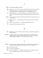
Document Revision History
Revision
Date
Description
0
10/07/08
Initial release.
1
2/24/09
General Update for compatibility of SLM-5650A software version 1.5.2.
2
3/16/10
General Update for compatibility of SLM-5650A software version 1.7.1.
{ This Page is Intentionally Blank }
Table of Contents
Chapter 1
General
How to Use This Manual . . . . . . . . . .
Manual Organization . . . . . . . . . .
Chapter 1 — General . . . . . . . .
Chapter 2 — Using Parameter Editor
Appendix A — Glossary . . . . . . .
Conventions and References . . . . . .
.
.
.
.
.
.
1-1
. 1-1
. 1-1
. 1-1
. 1-1
. 1-2
Product Description . . . . . . . . . . . . . . 1-3
Introduction . . . . . . . . . . . . . . . . . 1-3
Parameter Editor Features . . . . . . . . . 1-3
Customer Support . . . . . . . . . . . . . . 1-4
Contact Information . . . . . . . . . . . 1-4
Reader Comments / Corrections . . . . 1-4
Chapter 2
Using Parameter Editor
General . . . . . . . . . .
DLL Files . . . . . . .
Updating DLL Files
Configuration Changes
.
.
.
.
.
.
.
.
.
.
.
.
.
.
.
.
.
.
.
.
.
.
.
.
.
.
.
.
.
.
.
.
.
.
.
.
. 2-1
. . 2-1
. . 2-2
. . 2-2
Parameter Editor Tree Menu . . . . . . . . . 2-3
Configuration Alert . . . . . . . . . . . 2-3
Working Mode . . . . . . . . . . . . . . . . 2-5
Role Designation . . . . . . . . . . . . 2-5
Vipersat . . . . . . . . . . . . . . . . .
Unit Name . . . . . . . . . . . .
Network ID . . . . . . . . . . .
Multicast Management Address
STDMA . . . . . . . . . . . . . . .
Enable STDMA . . . . . . . . .
Allocation Method . . . . . . . .
Cycles per Map . . . . . . . . .
Slot Data Length . . . . . . . .
Group ID . . . . . . . . . . . .
Stats Collection . . . . . . . . .
Guard Band . . . . . . . . . . .
Preamble . . . . . . . . . . . .
Burst Map Multicast IP Address .
Outbound IP Address for DPC .
Remote List . . . . . . . . . . .
Remote Removal . . . . . . . .
ToC
.
.
.
.
.
.
.
.
.
.
.
.
.
.
.
.
.
.
.
.
.
.
.
.
.
.
.
.
.
.
.
.
.
.
.
.
.
.
.
.
.
.
.
.
.
.
.
.
.
.
.
2-7
. 2-7
. 2-7
. 2-7
. 2-8
. 2-9
. 2-9
2-12
2-12
2-12
2-13
2-13
2-13
2-14
2-14
2-14
2-16
Switching . . . . . . . . . . . . . .
Slot Capacity . . . . . . . . . .
Switch Delay . . . . . . . . . .
Allocation . . . . . . . . . . . .
Step Up Threshold . . . . . . .
Step Down Threshold . . . . . .
Step Delay . . . . . . . . . . .
Excess Capacity . . . . . . . .
ToS (Type of Service) . . . . . .
DPC . . . . . . . . . . . . . . . .
Enable Dynamic Power Control
Speed-Up Eb/N0 Range . . . .
Target IP Address . . . . . . . .
Target Eb/N0 . . . . . . . . . .
Margin . . . . . . . . . . . . .
Maximum Power . . . . . . . .
Calibration . . . . . . . . . . .
Home State . . . . . . . . . . . . .
Mod . . . . . . . . . . . . . . .
Demod . . . . . . . . . . . . .
Routing . . . . . . . . . . . . . . . .
Routing in a Vipersat Network.
Creating the Static Routes . .
OSPF . . . . . . . . . . . . .
.
.
.
.
.
.
.
.
.
.
.
.
.
.
.
.
.
.
.
.
.
.
.
.
.
.
.
.
.
.
.
.
.
.
.
.
.
.
.
.
.
.
.
.
.
.
.
.
.
.
.
.
.
.
.
.
.
.
.
.
.
.
.
.
2-17
2-18
2-19
2-19
2-19
2-19
2-20
2-20
2-20
2-22
2-23
2-23
2-23
2-24
2-24
2-24
2-24
2-25
2-26
2-27
.
.
.
.
.
.
.
.
.
.
.
.
2-29
2-29
2-29
2-31
LAN . . . . . . . . . . . . . . . . . . . . . . 2-35
ARP . . . . . . . . . . . . . . . . . . . 2-37
WAN . . . . . . . . . . . . . . . . . . . . . 2-39
WAN-to-WAN Internal Multicast Address . 2-39
OSPF Application . . . . . . . . . . . 2-39
Quality of Service . . . . . . . . . . . . . 2-40
Differentiated Services Code Point (DSCP)
2-40
Class Selector 6 . . . . . . . . . . . 2-42
Expedited Forwarding . . . . . . . . 2-43
Assured Forwarding . . . . . . . . . 2-44
Default . . . . . . . . . . . . . . . . 2-45
NTP
. . . . . . . . . . . . . . . . . . . . . 2-46
Event Log
. . . . . . . . . . . . . . . . . . 2-47
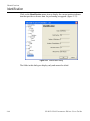
Identification . . . . . . . . . . . . . . . . . 2-48
Appendix A
Glossary
. . . . . . . . . . . . . . . . . . . . . A-1
i
Index
. . . . . . . . . . . . . . . . . . . Index-1
ii
SLM-5650A Parameter Editor User Guide
List of Figures
Chapter 2 Figures
Figure 2-1 Tree Menus, Vipersat Modes. . . . . 2-3
Figure 2-2 Alert, Parameter Conflict . . . . . . . . 2-4
Figure 2-3 Working Mode dialog . . . . . . . . . . . 2-5
Figure 2-4 Vipersat dialog . . . . . . . . . . . . . . . . 2-7
Figure 2-5 STDMA: Hub dialog . . . . . . . . . . . . 2-8
Figure 2-6 STDMA: Remote dialog . . . . . . . . . 2-8
Figure 2-7 Burst Slot Allocation Method . . . . . 2-9
Figure 2-8 STDMA Remote List dialog . . . . . 2-15
Figure 2-9 Add STDMA Remote dialog, ECM 2-15
Figure 2-10 STDMA Remote Removal dialog 2-16
Figure 2-11 Automatic Switching: Hub dialog 2-18
Figure 2-12 Automatic Switching: Remote dialog .
2-18
Figure 2-13 TOS Switch Rules dialog . . . . . . 2-21
Figure 2-14 Add TOS Rule dialog . . . . . . . . . 2-22
Figure 2-15 Dynamic Power Control dialog. . 2-23
Figure 2-16 DPC Calibration dialog. . . . . . . . 2-25
Figure 2-17 Home State dialog . . . . . . . . . . . 2-26
Figure 2-18 Modulator Home State dialog . . 2-27
Figure 2-19 Demodulator Home State dialog 2-27
Figure 2-20 Static Routes: Hub dialog . . . . . 2-30
Figure 2-21 Add Static Route dialog . . . . . . . 2-30
Figure 2-22 Open Shortest Path First dialog. 2-32
Figure 2-23 Local Area Network dialog . . . . . 2-35
Figure 2-24 Address Resolution Protocol dialog . .
2-37
Figure 2-25 Add Static ARP dialog . . . . . . . . 2-38
Figure 2-26 Wide Area Network dialog . . . . . 2-39
Figure 2-27 Class Selector 6 dialog . . . . . . . 2-42
Figure 2-28 Expedited Forwarding dialog . . . 2-43
Figure 2-29 Assured Forwarding dialog . . . . 2-44
Figure 2-30 Default dialog . . . . . . . . . . . . . . . 2-45
Figure 2-31 Network Time Protocol dialog . . 2-46
Figure 2-32 Event Log dialog . . . . . . . . . . . . 2-47
Figure 2-33 Identification dialog . . . . . . . . . . 2-48
LoF
iii
{ This Page is Intentionally Blank }
iv
SLM-5650A Parameter Editor User Guide
List of Tables
Chapter 2 Tables
Table 2-1 SLM-5650A Network Functions and
Roles . . . . . . . . . . . . . . . . . . . . . . . . . . . 2-6
Table 2-2 Differentiated Services, DSCP . . . . 2-40
LoT
v
{ This Page is Intentionally Blank }
vi
SLM-5650A Parameter Editor User Guide
CHAPTER
GENERAL
How to Use This Manual
This manual documents the features and functions of the Vipersat Parameter
Editor software user interface, and guides the user in how to use this product for
configuring a Vipersat SLM-5650A network unit.
Workstation users, as well as network administrators and operators responsible
for the configuration and maintenance of the Vipersat satellite network, are the
intended audience for this document.
Manual Organization
This User Guide is organized into the following sections:
Chapter 1 — General
Contains Parameter Editor product description, customer support information,
and manual conventions and references.
Chapter 2 — Using Parameter Editor
Covers the Parameter Editor dialogs and the associated fields that are used to
configure the SLM-5650A.
Appendix A — Glossary
A glossary of terms that pertain to Vipersat satellite network technology.
C h ap t e r 1 - G e n e r a l
1-1
How to Use This Manual
Conventions and References
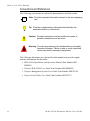
The following conventions are utilized in this manual to assist the reader:
NOTE
Note: Provides important information relevant to the accompanying
text.
Tip: Provides complementary information that facilitates the
associated actions or instructions.
Caution: Provides explanatory text that notifies the reader of
possible consequences of an action.
Warning: Provides precautionary text that describes a potentially
hazardous situation. Failure to take or avoid a specified
action may result in damage to equipment.
The following documents are referenced in this manual, and provide supplementary information for the reader:
• SLM-5650A Installation and Operation Manual (Part Number MN0000031)
• Vipersat SLM-5650A User Guide (Part Number MN-0000035)
• Vipersat Management System User Guide (Part Number MN/22156)
• Vipersat Load Utility User Guide (Part Number MN/22117)
1-2
S L M - 5 6 5 0 A P a r a m et e r E d i t o r U s e r G u id e
P r o d u c t D e s c r i p t io n
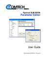
Product Description
Introduction
The Parameter (Param) Editor provides a simple graphical user interface (GUI)
for making configuration changes to modem/routers used in a Vipersat satellite
network. Accessible from both the VMS and VLoad, the Parameter Editor operates on the param files that store the operating parameters for network terminals.
This user guide documents the Parameter Editor as it applies to the SLM-5650A
satellite modem.
The Parameter Editor is the same in both the VMS and VLoad. However, the
way edited parameters are applied to the Vipersat network modem/routers
differs between the two. Once a modem’s configuration has been changed using
the VMS, the change is immediately applied to the modem. In contrast, changes
made using the VLoad utility are not applied until the new param file is Put
(uploaded) to the unit by the operator.
NOTE
Note: Many of the parameters will interact with other parameters. Carefully
read the instructions before making changes to a unit’s configuration
settings.
Parameter modifications may also be made directly to the modem/router using a
direct console connection, a Telnet connection, or the World Wide Web. Refer
to the modem/router’s documentation for details on making equipment parameter modifications directly at the unit.
For more information on using the Parameter Editor with the VMS, refer to the
Vipersat Management System User Guide.
For more information on using the Parameter Editor with VLoad, refer to the
Vipersat Load Utility User Guide.
Parameter Editor Features
The Parameter Editor software has the following features:
• Simple yet comprehensive graphical user interface.
• Integrates with both the VMS and VLoad.
• Context sensitive for device type as well as for unit role (Hub/Remote).
• Configuration alert error checking on range value parameters.
C h ap t e r 1 - G e n e r a l
1-3
C u s t o m e r S up p o r t
Customer Support
Contact Information
Contact Comtech Vipersat Network Products Customer Support for information
or assistance with product support, service, or training on any Vipersat product.
Mail:
Attn: CTAC
Comtech EF Data – Vipersat Network Products
3215 Skyway Court
Fremont, CA 94539
USA
Phone:
1+510-252-1462
Fax:
1+510-252-1695
Email:
[email protected]
Web:
www.comtechefdata.com
Reader Comments / Corrections
If the reader would like to submit any comments or corrections regarding this
manual and its contents, please forward them to a Comtech Vipersat Customer
Support representative. All input is appreciated.
1-4
S L M - 5 6 5 0 A P a r a m et e r E d i t o r U s e r G u id e
CHAPTER
USING PARAMETER EDITOR
General
DLL Files
The Parameter Editor is a shared run-time Dynamic Link Library (DLL) file
which is called from both VLoad and VMS software applications. It is used as
an extension to both of these programs in providing an extendable User Interface. This file resides in a locally sourced directory for access by the host application.
To access the Parameter Editor from either the VMS or VLoad, the appropriate
DLL files are required. There is a DLL file for each modem firmware version.
For example, ParamEdit-5.4.dll is utilized for modems that are running firmware v1.5.4. For networks that have multiple modem firmware versions, multiple DLL files are required.
Please note that the naming convention for these files may differ, depending on
what version of VMS or VLoad is used. Prior to VMS v3.6.2 and VLoad v3.4.1,
the convention used is ParamEdit-x.x.dll, where x.x identifies the modem firmware version. For VMS v3.6.2 and later, and VLoad v3.4.1 and later, the
convention used includes the modem designation and firmware version (e.g.,
ParamEdit-SLM5650A-x.x.dll).
C h ap t e r 2 - U s i n g P a r a m e t e r E di t o r
2-1
General
Updating DLL Files
To update the Parameter Editor for one or both of the installed applications,
VLoad and/or VMS, the new DLL file is simply copied into the appropriate
directory for that application.
VMS Update
On both the VMS Client machine and the VMS Server, copy the distributed
DLL file to the following directory:
C:\Program Files\Vipersat\VMS\3.0\bin
Vload Update
Copy the distributed DLL file into the same local directory that holds the VLoad
application (.exe).
These DLL file updates will not cause any disruption to the host applications.
Configuration Changes
When changes are made to a modem unit configuration with Parameter Editor,
these changes are saved by clicking on the OK button at the bottom of the
Editor window. Alternatively, these changes are ignored by either clicking on
the Cancel button or closing the Editor window.
Caution: Clicking the OK button saves all of the data from all of the menu
category dialogs simultaneously to the modem unit Param file. The
OK and Cancel buttons do not apply to any single dialog, but apply to
all dialogs in the Parameter Editor.
Because the Parameter Editor closes after a save operation, it is recommended
that all desired changes be input prior to clicking on the OK button.
2-2
S L M - 5 6 5 0 A P a r a m et e r E d i t o r U s e r G u id e
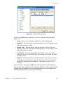
Parameter Editor Tree Menu
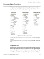
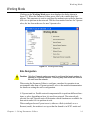
Parameter Editor Tree Menu
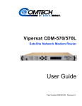
The Parameter Editor displays the editable parameter categories for each
network modem/router in the form of a tree menu. The tree appearance will vary
depending on the selected Working Mode, and whether the unit has both a
modulator and a demodulator, or a demodulator only.
Vipersat Hub
Vipersat Remote
Expansion w/o Mod
Figure 2-1 Tree Menus, Vipersat Modes
From the VMS, Parameter Editor is accessed by selecting the modem Configure
command.
From VLoad, Parameter Editor is accessed by clicking on the Edit Param File
button.
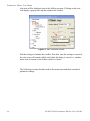
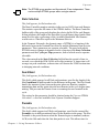
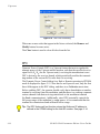
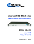
Configuration Alert
Parameter Editor performs a check of the configuration settings that are input by
the user. If any settings are found to be in conflict for the unit, an alert message
is generated to inform the user that an adjustment is necessary. When a dialog
containing a conflicting parameter setting is exited, an alert icon will appear in
front of the associated menu item (figure 2-2). Upon re-opening the dialog, an
C h ap t e r 2 - U s i n g P a r a m e t e r E di t o r
2-3
P a r a m et e r E d i t o r T r e e M e n u
alert icon will be displayed next to the field in question. Clicking on the icon
will display a pop-up info-tip that explains the conflict.
Figure 2-2 Alert, Parameter Conflict
Edit the setting to eliminate the conflict. Note that, once the setting is corrected,
the alert icons will remain visible until either the dialog is exited (i.e., another
menu item is chosen) or the Editor window is closed.
The following sections describe each of the menu items and their associated
parameter settings.
2-4
S L M - 5 6 5 0 A P a r a m et e r E d i t o r U s e r G u id e
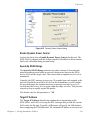
W or k i ng M o d e
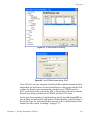
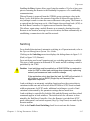
Working Mode
Clicking on the Working Mode menu item displays the dialog shown in
figure 2-3. When the Parameter Editor opens, this is the window that first
appears. This parameter is used to configure the modem/router with the function
(role) it is to perform in the network. The first four modes listed are for Vipersat
roles, the last four modes are for non-Vipersat roles.
Figure 2-3 Working Mode dialog
Role Designation
Caution: Only the Vipersat modes are used to configure the target modem to
operate in a Vipersat network. Selecting any other mode will remove
the unit from the network.
When using the Parameter Editor to configure a modem for operation in an
environment other than a Vipersat network, refer to the modem documentation
for details on setting the unit’s configuration.
A Vipersat unit is a flexible network component able to perform different functions, or roles, depending on how it is used in a network. The network role
selected for each Vipersat unit will determine which functions are available for
that unit in order for it to perform its role.
When configured as an Expansion unit, either as a Hub (switched) or as a
Remote (mesh), the modem is set up so that the demod is in SCPC mode and
C h ap t e r 2 - U s i n g P a r a m e t e r E di t o r
2-5
Working Mode
available as a resource for dedicated communications with the other end of the
satellite link.
Table 2-1 lists some typical network functions and the corresponding network
role a sample SLM-5650A must have to perform its functions.
Table 2-1 SLM-5650A Network Functions and Roles
SLM-5650A Network Function
Hub TDM / Burst Controller providing STDMA
Timing Maps
Hub Switched Demodulator
Remote STDMA Modem
Remote Mesh Demodulator
2-6
Hub Remote Expansion
X
X
X
X
X
X
S L M - 5 6 5 0 A P a r a m et e r E d i t o r U s e r G u id e
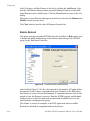
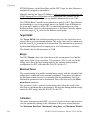
Vipersat
Vipersat
Clicking on the Vipersat menu item displays the dialog shown in figure 2-4.
Figure 2-4 Vipersat dialog
Unit Name
Enter any name (24 characters or less) for the node which serves to identify the
Vipersat unit on the network.
Network ID
The number entered in the Network ID field defines the network of which the
target Vipersat unit is a member. All devices in a common network will share
the same network ID.
The network ID is used by the VMS to identify Vipersat units within a network
and allows the VMS to manage multiple networks, each with its own unique
network ID number.
Multicast Management Address
The Multicast Management Address is the IP address assigned to all Vipersat
modem units in the network that are managed by the VMS server. This address
must match the corresponding Management Multicast Address that is specified
for the VMS (in the Vipersat Manager Properties) in order for the modem units
to receive the maintenance and control packets that are multicast by the VMS.
C h ap t e r 2 - U s i n g P a r a m e t e r E di t o r
2-7
Vipersat
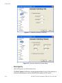
STDMA
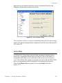
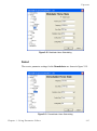
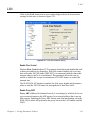
Clicking on the STDMA menu item displays the STDMA dialog, the appearance of which will vary based on whether the unit function is set to Hub or
Remote (as selected from Working Mode), and the chosen allocation method.
Figure 2-5 STDMA: Hub dialog
Figure 2-6 STDMA: Remote dialog
2-8
S L M - 5 6 5 0 A P a r a m et e r E d i t o r U s e r G u id e
Vipersat
For example, the SLM-5650A shown in figure 2-5 is operating as a Hub, with
the allocation method set for Entry Channel Mode. Some of the parameter fields
may be unavailable for input (grayed out), depending upon the method that is
selected. The screen shown in figure 2-6 shows an SLM-5650A being used as a
Remote, with only a subset of the fields that appear for a Hub unit.
If the SLM-5650A is being used as an Expansion unit — for either a Hub or a
Remote — no STDMA menu options are available since it is only used as an
SCPC demod.
Enable STDMA
In order to utilize the Vipersat STDMA feature (burst mode) in this modem, the
Enable STDMA check box must be selected.
For a Hub STDMA Burst Controller or a Remote STDMA modem, this feature
must be Enabled. For a private point-to-point SCPC modem, Hub or Remote,
this feature must be Disabled.
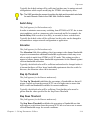
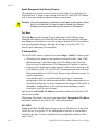
Allocation Method
Active for Hub modems only.
When the target SLM-5650A is being used as a Hub, it has five modes of operation which define the method the Burst Controller uses to allocate slot timing.
Figure 2-7 Burst Slot Allocation Method
Select an STDMA mode of operation for the SLM-5650A from the Allocation
Method drop-down menu shown in figure 2-7.
• Fixed - All Remotes get the same size slot, regardless of each Remote’s
activity.
• Dynamic Slot - Slot size is adjusted each cycle depending on activity
during the previous cycle.
• Dynamic Cycle - A Dynamic Cycle allows changing the cycle time—and
corresponding latency—as loads change, always providing minimum
latency for the current traffic load.
• GIR - Guaranteed Information Rate allows assigning guaranteed data
rates for each Remote in the group within the burst channel.
C h ap t e r 2 - U s i n g P a r a m e t e r E di t o r
2-9
Vipersat
• Entry Channel - Entry Channel Mode provides an immediate acquisition
into an SCPC channel upon Remote burst registration.
NOTE
Note: If the Hub STDMA mode is GIR (Guaranteed Information Rate) or Entry
Channel, normal load switching is automatically disabled. In GIR mode,
the Remote is switched to SCPC as soon as the GIR threshold is
reached, if there is a switch rate defined. In Entry Channel Mode, the
Remote is switched to SCPC as soon as the Hub receives the first transmission from the Remote.
The bandwidth allocation method that is selected will determine which of the
associated parameters are available and applicable.
Fixed
In the Fixed mode, all Remotes have the same slot size regardless of type of
traffic or load. No calculations are made to actively change slot size when operating in this mode.
Fixed mode minimizes the amount of jitter between Remote transmission times,
and is useful for tuning STDMA as well as for troubleshooting purposes.
Dynamic Slot
In the Dynamic Slot mode, the slot size for each Remote is computed based on
the time (at the current data rate) needed to transmit all the Bytes in Queue. If
the result is less than the minimum slot size or more than the maximum slot
size, the slot is adjusted accordingly.
This mode allows the Burst Controller to provide additional slot time in the
cycle to Remotes with higher traffic demands, increasing throughput and alleviating congestion.
Dynamic Cycle
In the Dynamic Cycle bandwidth allocation method, available bandwidth is
allocated to Remotes proportionally based on their current bandwidth needs.
The bandwidth requirements are determined by the number of bytes in queue
for each Remote divided by the total number of bytes in queue for all Remotes
to determine the percentage of bandwidth to allocate for each Remote.
This mode provides improved efficiency of STDMA due to faster cycle times
during periods of light traffic demands, thus providing minimum latency for the
current load.
2-10
S L M - 5 6 5 0 A P a r a m et e r E d i t o r U s e r G u id e
Vipersat
GIR (Guaranteed Information Rate)
In the GIR mode, the initial computed slot size value is the same as the
Dynamic Cycle mode except there is no maximum limit. After all Remotes have
been assigned slots, the burst map is checked to see if the total cycle length
exceeds 1 second. If not, then all requirements are satisfied and the burst map is
complete. However, if the cycle is greater than one second, then the slots are
adjusted proportionally so that all Remotes receive at least their guaranteed rate
plus whatever excess is still available.
GIR mode allows guaranteed information rates to be set for each Remote in the
group. When the one second restriction is exceeded, Remotes without a specified GIR are reduced to the global minimum slot size and the remaining bandwidth is distributed to Remotes that have been assigned a GIR rate, thus
ensuring additional bandwidth for these units when needed.
NOTE
Note: GIR allocations are restricted so that assigned GIR totals cannot exceed
the available bandwidth to insure proper bandwidth allocation when the
network is overloaded. Attempts to enter a GIR which would result in a
spin time of more than one second will error out.
Entry Channel
The Entry Channel Mode (ECM) provides Remotes in the group with a shared
channel in which they can gain initial access to the network. Since very small
STDMA data rates are required in this configuration, a larger number of
Remotes can share the cycle. As soon as the Hub receives an STDMA ACK
from the Remote, it initiates an immediate switch to SCPC mode based on the
policy set for that Remote. Note that the switch occurs as soon as the Hub
receives an ACK even though there may not be traffic at that time. The persistence of the link will be determined by the unit’s flag settings.
When choosing Entry Channel as the Hub type for the STDMA Controller, the
Auto switching feature must be Enabled on this Hub unit, and switching policies
for the Remotes must be configured (refer to the section “Remote List” on
page 2-14). Corresponding Remote modems must be configured with Auto
switching and Load switching Enabled.
This mode is designed to accommodate the needs of a Remote that will not be
continuously connected to the network, but which has the need to be able to
make an on-demand connection when required, such as in a mobile application.
In the event of a power outage, Entry Channel provides a bandwidth-efficient
method for Remotes with low latency requirements to re-enter the network once
power is restored.
NOTE
Note: In ECM, the switch occurs as soon as the Hub receives an STDMA ACK
from the Remote, even though there may not be traffic at that time.
C h ap t e r 2 - U s i n g P a r a m e t e r E di t o r
2-11
Vipersat
Cycles per Map
This menu item, which appears for all Hub types except Dynamic Cycle and
GIR, displays the number of spin cycles that will occur between each broadcast
of the Burst Map by the Burst Controller to the Remotes. One cycle is the
amount of time it takes for all Remotes in a group to burst on the common channel. The burst map provides each Remote with its allocated bandwidth and position in the cycle.
For Dynamic Cycle and GIR configurations, the number of cycles per map is
automatically set to 1 in order to ensure optimum performance for these Hub
types.
Slot Data Length
This setting specifies the Slot Data Length in milliseconds for the Remotes in
the group, and represents the amount of data that can be transmitted or received
in one spin of the STDMA cycle by each of the Remotes belonging to that
group. This is the amount of time that the Remote is provided to send data in the
cycle.
Depending on the Hub allocation type that is defined for the modem, the appearance of this setting will vary and may be comprised of one or two parameters:
• Fixed – Slot Length
• Dynamic Slot – Slot Nominal, Slot Minimum
• Dynamic Cycle – Slot Minimum, Slot Maximum
• GIR – Slot Minimum
• Entry Channel – Slot Length, Slot Maximum
Group ID
This field appears for Hub and Remote modems.
The STDMA Group ID number defines a group of equipment which will
respond to the output of the Burst Controller. This group is addressable within a
network which, in turn, is defined by the network ID number assigned to the
SLM-5650A.
Allocation of bandwidth is shared among the Remotes in an STDMA group.
Depending on the number of Remotes in a network, a Hub may have multiple
Burst Controllers, each with its own set of Remotes. This is accomplished by
assigning a unique Group ID number to each controller and its associated
Remotes.
2-12
S L M - 5 6 5 0 A P a r a m et e r E d i t o r U s e r G u id e
Vipersat
NOTE
Note: The STDMA group number and the network ID are independent. There
can be multiple STDMA groups within a single network.
Stats Collection
This field appears for Hub modem only.
The Burst Controller monitors statistics in the received ACK from each Remote.
The statistics report the fill status of the STDMA buffers. The Burst Controller
builds a table of the group and calculates the relative buffer fill for each Remote.
It then calculates the length of the Data Slot for each Remote based on the Minimum Slot Size plus a percentage of the Available Bandwidth. Idle Remotes
would receive a Data Slot equal to the Minimum Slot size.
In the Dynamic Slot mode, the dynamic range of STDMA is a function of the
difference between the Nominal Data Slot size and the Minimum Data Slot size
parameters. These parameters are operator selectable. The speed with which
STDMA reacts to changes in dynamic load is a function of the Stats Collection
parameter and the Cycles per Map parameter, both of which are also operator
selectable.
The value entered in the Stats Collection field defines the period of time, in
seconds, over which the SLM-5650A will collect statistics. A longer time will
average out peak conditions, a shorter time will shorten the VMS reaction time
to changing network conditions.
Guard Band
This field appears for Hub modem only.
This field, which appears for all Hub configurations, specifies the length of the
Slot Guardband in milliseconds for the Remotes in the group. The Slot Guardband is the amount of time between the point when one Remote completes
transmitting data and the point when the next Remote in the cycle begins transmitting. This prevents the Remote from overrunning the next terminal in the
cycle.
The setting for this parameter should be obtained using the Vipersat STDMA
Calculator—a free tool available from Vipersat Customer Support.
Preamble
This field appears for Hub modem only.
This field, which appears in all Hub configurations, specifies the current Slot
Preamble size in milliseconds and bytes for the Remotes in the group. The Slot
Preamble is the period between when the Remote begins to transmit (sends an
ACK) to the Hub and when the first data packet is sent. This allows time for
C h ap t e r 2 - U s i n g P a r a m e t e r E di t o r
2-13
Vipersat
signal lock to occur before data is sent, thus preventing data loss. Higher data
rates allow for a shorter preamble, since it is easier to achieve signal lock.
The setting for this parameter (default = 0) should be obtained using the Vipersat STDMA Calculator—a free tool available from Vipersat Customer Support.
Burst Map Multicast IP Address
This field appears for Hub and Remote modems.
This field is used to define the IP Address for the Burstmap Multicast that is
sent out by the STDMA Burst Controller at the Hub to all of the associated
Remotes in that group. This address must be the same for all members of the
group. The burstmap is a proprietary message sent from the Hub to all Remotes,
at regular intervals, specifying the relative start time and duration for each
terminal to transmit.
Outbound IP Address for DPC
This field appears for Hub modem only.
This field, which appears for all Hub configurations, defines the current
Outbound IP Address. This identifies the Hub device that is supplying the
TDM outbound to the satellite. Specifying this address is necessary when
configuring a Hub that utilizes a Burst Controller that is a separate device from
the TDM modem.
This address must always be defined when the DPC feature is to be used,
whether or not the BC and TDM are separate devices. The Outbound IP address
will be the same as the Burst Controller IP address when the Burst Controller
and the TDM modem are the same device.
Remote List
This menu item appears under STDMA when the Unit Role is Hub, and is used
to define and make modifications to the Remotes that belong to the STDMA
group for the Hub Burst Controller.
Click the Add button to add a new Remote(s) to the list for this Burst Controller. Define the IP Address, Name, and switching policies for the Remote.
An example for an ECM Hub is shown in figure 2-8 and figure 2-9. Enter the
SCPC Data Rate and the Switch Type to determine when the Remote will
switch and the desired starting point for communications. Note that a Data Rate
value of 0 will prevent the Remote from switching out of STDMA mode and
into SCPC mode.
2-14
S L M - 5 6 5 0 A P a r a m et e r E d i t o r U s e r G u id e
Vipersat
Figure 2-8 STDMA Remote List dialog
Figure 2-9 Add STDMA Remote dialog, ECM
For a GIR Hub, enter the automatic load Switch Rate and the Guaranteed Information Rate for the Remote. Set the Switch Rate to a value greater than the GIR
to allow the Remote to be automatically switched out of STDMA and into
SCPC mode when traffic exceeds the GIR. A Switch Rate of 0 will prevent the
Remote from being switched out of STDMA and into SCPC mode.
Switch type 0 corresponds to Load Switching. Switch types 64 through 255 are
user-defined, and must match VMS policies. When choosing Load Switching as
the Switch Type, the associated Remote must have the Load Switching feature
Enabled (see the section “Switching” on page 2-17).
C h ap t e r 2 - U s i n g P a r a m e t e r E di t o r
2-15
Vipersat
After field entry, add this Remote to the list by clicking the Add button. Note
that the Add Remote dialog remains open after adding a Remote so that additional Remotes can be added easily. Click the Close button to return to the List
dialog.
When one or more Remotes that appear in the list are selected, the Remove and
Modify buttons become active.
The Clear button is used to clear all Remotes from the list.
Remote Removal
This menu item appears under STDMA when the Unit Role is Hub, and is used
to define and make modifications to the Remotes that belong to the STDMA
group for the Hub Burst Controller.
Figure 2-10 STDMA Remote Removal dialog
Once Enabled (figure 2-10), the value entered for the number of Cycles defines
the amount of time with no communication from a Remote to the Hub before
that Remote is removed from the Burstmap. If communications are lost for this
period of time, the Remote is removed from the STDMA group, and the bandwidth resources it had been allocated are then made available for use by the
other Remotes remaining in the group.
This feature is useful, for example, in an SNG application where a mobile
Remote has finished its assignment and has shut down.
2-16
S L M - 5 6 5 0 A P a r a m et e r E d i t o r U s e r G u id e
Vipersat
Enabling the Retry feature allows specifying the number of Cycles to have pass
prior to returning the Remote to the Burstmap for purposes of re-establishing
communications.
When a Remote is removed from the STDMA group, entering a value in the
Retry Cycles field defines the amount of time that is allowed to pass before a
retry attempt is made to return the removed Remote to the group. The Remote is
re-entered into the burst map cycle; if the Remote does not burst back (ACK) to
the Hub Burst Controller, it is again removed from the Burst Map.
This allows, again using a mobile Remote as an example, shutting down the
Remote at one location, moving it to a new location, and then automatically reestablishing a connection to the satellite network.
Switching
For a detailed description of automatic switching in a Vipersat network, refer to
the Vipersat Management System User Guide.
Clicking on the Switching menu item displays the dialog shown in figure 2-11
(Hub) or figure 2-12 (Remote).
For a unit being used as an Expansion unit, no switching options are available.
This type of unit operates in dedicated SCPC mode and all switching control is
performed by the VMS.
Caution: Load switching must be enabled on all SLM-5650As in a network in
order for VMS to utilize load switching when dynamically optimizing
network performance as load conditions change.
If the application rate is less than the load, the VMS will not switch. It
will, however, set up SHOD (Single Hop on Demand) if the
application requires it.
Load switching is an automatic switching function where the system detects
variations in data rate and will switch from STDMA to SCPC based on bandwidth requirements. In SCPC mode, additional switching as a result of load
variation is determined by the parameter settings that are made here.
Load switching is controlled by both the Hub and the Remote, and thus related
commands appear in both windows. The initial switch for a Remote is determined by the Hub Burst Controller. Once the Remote is swiched into SCPC
mode, subsequent Load switch requests (Step Up, Step Down) are made by the
Remote modem.
Click in the Enable Load Switching check box to activate this feature.
C h ap t e r 2 - U s i n g P a r a m e t e r E di t o r
2-17
Vipersat
Figure 2-11 Automatic Switching: Hub dialog
Figure 2-12 Automatic Switching: Remote dialog
Slot Capacity
This field appears for Hub modems only.
The Slot Capacity field allows setting the threshold or level of slot-capacity at
which the transmission switches from STDMA mode to SCPC mode.
2-18
S L M - 5 6 5 0 A P a r a m et e r E d i t o r U s e r G u id e
Vipersat
Typically the default setting will be sufficient, but there may be unique network
configurations which require modifying the STDMA slot capacity value.
Tip: The VMS provides the means for setting the high and low switch rate limits
for each Remote. Refer to the VMS User Guide for details.
Switch Delay
This field appears for Hub modems only.
In order to minimize unnecessary switching from STDMA to SCPC due to transient conditions, such as a temporary spike in network traffic for example, the
Switch Delay field is used to set a delay, in seconds, before a switch occurs.
Typically the default value will be sufficient, but this value can be changed to
accommodate a unique network configuration or application.
Allocation
This field appears for Hub modems only.
The Allocation field allows adding a fixed percentage to the channel bandwidth
request to accommodate additional bandwidth requirements which may occur
after a switch is made from STDMA to SCPC mode. This setting provides a
means to balance known future bandwidth requirements for the channel against
efficient bandwidth utilization.
Typically, the default value will be sufficient and need not be changed unless it
is known that there will be a larger bandwidth requirement after the switch. In
this case, the allocation value can be increased.
Step Up Threshold
This field appears for the Remote modem only.
The Step Up Threshold establishes the percentage of bandwidth use that will
trigger a switch up from the present SCPC rate to a higher rate to ensure that
there is sufficient bandwidth available for current conditions.
Typically, the default value will be sufficient. Note that this value must be
greater than the value specified for the Step Down Threshold.
Step Down Threshold
This field appears for the Remote modem only.
The Step Down Threshold establishes the percentage of bandwidth use that
will trigger a switch down from the present SCPC rate to a lower rate to ensure
efficient bandwidth usage for current conditions.
C h ap t e r 2 - U s i n g P a r a m e t e r E di t o r
2-19
Vipersat
Typically the default value will be sufficient. Note that this value must be less
than the value specified for the SCPC Step Up Threshold.
Step Delay
This field appears for the Remote modem only.
The Step Delay feature provides a switching delay period to ensure that a
premature switch up or down in the SCPC rate does not occur due to a temporary rise or fall in traffic.
Excess Capacity
This field appears for the Remote modem only.
During each SCPC Step Up switch, the excess capacity data rate value entered
by this command is added to the new SCPC data rate. This excess is added each
time an SCPC Step Up switch occurs. This setting makes additional bandwidth
available for when the demand arises while minimizing Step Up switching
events.
ToS (Type of Service)
This menu item appears under Switching when the Unit Role is Remote, and is
used to define and make modifications to the ToS switching rules.
Type of Service (ToS) is defined by an eight bit field within an IP packet header
that is used to set up per-hop-based QoS rules for prioritizing packets. Because
the ToS field remains untouched by most encryption methods, ToS switching
provides an alternative means of SCPC switching when encryption prevents the
detection of SIP and H.323 protocols.
ToS detection occurs in the Remote modem which only looks at traffic that is
passed in the LAN-to-WAN (Remote to Hub) direction. Once the ToS Switch
Detection feature is enabled, the Remote modem will send a switch request to
the VMS when a packet stamped with the ToS is detected. The request contains
the destination IP address of the ToS stamped packet, the desired SCPC rate,
and the VMS Switch Type (policy #). If available hardware and bandwidth
exist, the VMS will establish the SCPC carrier automatically.
ToS switch detection is controlled by the Remote, and thus appears only in the
Automatic Switching: Remote dialog where it is Enabled via a check box
(figure 2-12).
ToS switch rules are configured by clicking on the TOS menu item that appears
for Remote modems, as shown in figure 2-13.
2-20
S L M - 5 6 5 0 A P a r a m et e r E d i t o r U s e r G u id e
Vipersat
Figure 2-13 TOS Switch Rules dialog
Click on the Add button to add a new ToS rule, using the dialog shown in
figure 2-14.
• Name – Enter a user-defined text label for circuit identification.
• Identifier – Enter an integer value in the range of 1 to 63. Entering a value
of 0 will result in no switch.
• Switch Type – Enter an integer value in the range of 64 to 254 at the
prompt to inform the VMS what switching policy to use. Entering a value
of 0 will result in no switch.
• Switch Rate – Enter the desired data rate for this service type. Valid
entries are from 0 to 155000000 bps. This setting will override the VMS
set policy value.
• Timeout – This timer monitors the defined packet flow. Once data stops
for the duration of the timer setting, the link state will be restored to the
Home State condition for this Remote. Valid entries are from 1 to 60
seconds.
After field entry, clicking the Add button will update the ToS Switch Rules
table with the new configuration. Note that the Add Type of Service Rule dialog
remains open after adding a rule so that additional rules can be added easily.
Click the Close button to return to the ToS dialog.
C h ap t e r 2 - U s i n g P a r a m e t e r E di t o r
2-21
Vipersat
Figure 2-14 Add TOS Rule dialog
When one or more rules that appear in the list are selected, the Remove and
Modify buttons become active.
The Clear button is used to clear all rules from the list.
DPC
Dynamic Power Control (DPC) is a Vipersat feature that acts to regulate the
transmit power of the Vipersat satellite modem, such that the specified receive
signal level (Eb/N0) for the Vipersat unit(s) receiving the transmission is met.
DPC is driven by the receiver demod, which periodically notifies the transmitting modem of the current Eb/N0 value that it is receiving.
The Dynamic Power Control dialog for a Hub or Remote operating in STDMA
mode is displayed in figure 2-15. Note that for an Expansion unit, only the first
three fields appear in the DPC dialog, and there is no Calibration menu item.
Before enabling DPC, the operator should verify that a demodulator at another
terminal is receiving from this modulator, and that there is a working communications channel from that receiving station back to the modulator terminal
(In-Band communications). Additionally, since DPC potentially controls the
full power range of the modulator’s output power, it is recommended that the
terminal be commissioned and calibrated before usage.
Tip: The DPC feature will not function unless the Outbound IP address is
defined in the STDMA dialog for the Hub BC modem. See page 2-14.
2-22
S L M - 5 6 5 0 A P a r a m et e r E d i t o r U s e r G u id e
Vipersat
Figure 2-15 Dynamic Power Control dialog
Enable Dynamic Power Control
Activate the check box to Enable Dynamic Power Control for this unit. The
SLM-5650A is shipped with this feature turned off (Disabled) to allow entrance
link levels calibration during terminal setup.
Speed-Up Eb/N0 Range
The Speed-Up Eb/N0 Range parameter provides a means of decreasing the
power adjustment period when an excessive delta occurs between the Eb/N0
receive level and the target value. This ensures that an optimal receive level is
maintained.
Normally, the DPC message is sent every 30 seconds from each terminal in the
network. Should the received Eb/N0 level at the demodulator ever fall outside
the specified range, the terminal increases its message send rate to every 10
seconds until the receive level is again within the range set value. This provides
a speed-up loop to rapidly regain link quality.
The default value for this parameter is 3 dB.
Target IP Address
The Target IP Address identifies the modem that is transmitting to this
SLM-5650A, and will be receiving the DPC messages that provide the current
Eb/N0 value for this unit. Typically, all Remotes will specify the Hub modem
that is supplying the TDM outbound. The Outbound IP address is sent out to all
C h ap t e r 2 - U s i n g P a r a m e t e r E di t o r
2-23
Vipersat
STDMA Remotes via the Burst Map, and the DPC Target for these Remotes is
automatically mapped to that address.
Manually entering the Target IP Address is only necessary for modems that are
SNMP managed Out-of-Band and will be utilizing the DPC feature. For InBand modems, the target addresses are handled automatically by the VMS.
The STDMA Burst Controller is not permitted to specify a DPC Target because
the demodulator is receiving multiple bursts very rapidly from all Remotes in
the group and is unable to utilize DPC to control the transmit power of the
Remote modems. However, the transmit power of the Burst Controller adjusts
to meet the target Eb/N0 value for the Remotes in the group.
Target Eb/N0
The Target Eb/N0 is the desired operating receive level for closed loop servo
control, and is set in the transmit modem. This is the value used for comparison
with the actual Eb/N0 from the receiving modem. This information is processed
by the transmitting terminal for output power level adjustment as necessary.
The default value for this parameter is 10 dB.
Margin
The DPC Margin value is the offset between the current power level and the
upper power limit for the waveform. This parameter field is read only in this
dialog, and reflects the input setting made by the operator during modem
configuration for DPC with either the Web GUI or the CLI.
Maximum Power
The commissioning of a satellite terminal must comply with the calculated link
budget that is conducted before terminal installation. Using these calculations,
the maximum transmit power level permitted for the modulator(s) based on
link/satellite parameters can be determined. This is the value set by the Maximum Power parameter.
This parameter field is read only in this dialog, and reflects the result of the
Max Power calculation that is performed by the operator during modem configuration for DPC using either the Web GUI or the CLI.
Calibration
This menu item appears under DPC (except for Expansion units), and is used to
view the parameters relating to the calibration of the power control function.
The Maximum Data Rate, Maximum Coding Rate, and Maximum Modula2-24
S L M - 5 6 5 0 A P a r a m et e r E d i t o r U s e r G u id e
Vipersat
tion values are the highest achievable values as determined from the link
budgetary calculations performed for this site.
Figure 2-16 DPC Calibration dialog
These parameter fields are read only in this dialog, and reflect the input settings
made by the operator during modem configuration for DPC with either the Web
GUI or the CLI.
Home State
A SLM-5650A’s Home State consists of those parameters which provide a
known RF configuration that the unit will return to, either as the result of a
command by the VMS, or as it comes back on line from a reset or a power
cycle. These Home State settings are typically selected so that the SLM-5650A
goes to a configuration which is optimum for its function in the network.
Click on the Home State menu item to access the Enable check box
(figure 2-17).
C h ap t e r 2 - U s i n g P a r a m e t e r E di t o r
2-25
Vipersat
Figure 2-17 Home State dialog
A superset of the Home State called the Modem Group Command (MGC) is
displayed here, containing every base modem parameter including Vipersat.
The Home State consists of both the modulator parameters and the demodulator
parameters. Click on the Mod and Demod menu items for configuration.
Mod
The transmit parameter settings for the Modulator home state are shown in
figure 2-18.
Note that the valid range for the Data Rate will vary depending on the Modulation Type and Coding Rate.
When operating in Vipersat mode, the Coding Type must be set to Turbo and
Coding Rates of 1/2, 2/3, and 1/1 are not valid.
2-26
S L M - 5 6 5 0 A P a r a m et e r E d i t o r U s e r G u id e
Vipersat
Figure 2-18 Modulator Home State dialog
Demod
The receive parameter settings for the Demodulator are shown in figure 2-19.
Figure 2-19 Demodulator Home State dialog
C h ap t e r 2 - U s i n g P a r a m e t e r E di t o r
2-27
Vipersat
Note that the valid range for the Data Rate will vary depending on the Modulation Type and Coding Rate.
When operating in Vipersat mode, the Coding Type must be set to Turbo and
Coding Rates of 1/2, 2/3, and 1/1 are not valid.
2-28
S L M - 5 6 5 0 A P a r a m et e r E d i t o r U s e r G u id e
Routing
Routing
Routing in a Vipersat Network
SLM-5650A Modem Routers operating in Vipersat mode do not use the Multipoint, Point to Point, or Bridge network modes described in the SLM-5650A
Installation and Operation Manual. There is no HDLC address in a Vipersat
network; instead, the SLM-5650A role designation — Hub or Remote, Expansion unit or not — determines routing rules that prevent multicast loops. This
simplifies the configuration of a Vipersat network.
Because satellite networks are often used as extensions for access to services
such as the Internet or the PSTN, they lend themselves quite readily to private
addressing. For example, to provide Internet access to the satellite network, only
the Hub requires a public IP address in order for the entire satellite network that
is controlled by the Hub to have access to the Internet backbone. Utilizing
Network Address Translation (NAT), the administrator can effectively address
the network using a minimum number of static route statements.
Example:
The IP address 172.16.0.0 is the private address network number for class B
networks. If there is a router at the Hub with a connection to the Internet, the
operator can define the local network as a class B. If the operator splits the
Class B in half and points the upper half toward the satellite there will be
over 16,000 usable addresses at the Hub as well as at the Remotes.
By putting the one route statement “Remotes 172.16.128.0/17 WAN to
LAN” in the TDM Hub modem, and by using the route statement “GW
0.0.0.0/0 LAN to WAN” at each of the Remote modems, the network will
successfully route packets. The Remotes can then be subnetted as class C
networks or below. Additional routers at the Remotes can be added for
unusually large sites, allowing an additional layer of NAT without requiring
any more explicit routing within the Vipersat Modem Routers.
Refer to the SLM-5650A Installation and Operation Manual for additional
information on entering routes.
Creating the Static Routes
The following procedure outlines the basic route structure that the target
SLM-5650A will require for its role in the network. One of the key routes that
must be created is a default gateway address for routing the data traffic that is
received by the unit.
C h ap t e r 2 - U s i n g P a r a m e t e r E di t o r
2-29
R o ut i n g
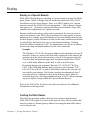
1.
From the tree menu, select Routing to open the Static Routes dialog.
The static routing configuration for a typical Hub unit is shown in
figure 2-20.
Figure 2-20 Static Routes: Hub dialog
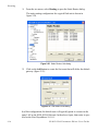
2.
Click on the Add button to create the first route that will define the default
gateway (figure 2-21).
Figure 2-21 Add Static Route dialog
In a Hub configuration, the default route will typically point to a router on the
same LAN as the SLM-5650A Hub unit. In the above figure, that router is specified as the Next Hop address 10.1.0.1.
2-30
S L M - 5 6 5 0 A P a r a m et e r E d i t o r U s e r G u id e
Routing
In a Remote configuration, the default route will typically point to the satellite
modem (WAN) used for communications back to the Hub.
3.
Enter the Destination IP Address, the number of Subnet Bits in the
subnet mask, the Description of the route (GW), the route Interface (LAN
or WAN), and either the Next Hop address (LAN interface) or the HDLC
Address (WAN interface). The system administrator can supply this information, if necessary.
In a Hub role, for example, enter the name of the route (e.g., DFG), enter
0.0.0.0 for the destination IP address and 0 for the mask, select LAN for
Ethernet interface, then enter the IP address of the appropriate router or
modem for the next hop.
If this Hub unit is providing the TDM outbound, a route statement or
statements defining satellite communications with the Remote units must
be entered as well. One option is to enter a single super-route that will
handle satellite communications with all of the remote subnets.
4.
Click on the Add button to add the new route to the table.
When one or more routes that appear in the list are selected, the Remove and
Modify buttons become active.
The Clear button is used to clear all routes from the list.
5.
When all routes have been defined, click on OK to save the settings.
OSPF
The Vipersat OSPF (Open Shortest Path First) feature in the Comtech
SLM-5650A modem/router provides for dynamic routing functionality. Route
changes from the Hub are broadcast to the Remotes via a dedicated WAN-toWAN multicast address. Route changes from a Remote are unicast to the Hub.
Static routes that are manually entered into the route table by the operator are
separate from these dynamic routes and are not managed as part of the OSPF
system.
The support for OSPF functionality in the SLM-5650A modem causes routers
that are external and connected to the Vipersat satellite network to “see” the
entire SLM-5650A network as if it were a single router.
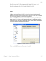
Click on the OSPF menu item that appears under Routing (except for Expansion units) to access and configure the Open Shortest Path First settings for this
unit, as shown in figure 2-22.
C h ap t e r 2 - U s i n g P a r a m e t e r E di t o r
2-31
R o ut i n g
Figure 2-22 Open Shortest Path First dialog
With the exception of Topology (Mesh/Star), the parameters on this page are
used to configure the standard implementation of OSPF.
To activate the OSPF feature for this modem, click in the Enable OSPF check
box and set the parameter fields as described below. For the majority of
networks, the default settings are recommended.
NOTE
Note: For systems that are already operating with OSPF, activation of any
parameter changes will result in a momentary stopping and re-starting of
the OSPF process.
Network Address
The Network Address parameter specifies the IP address of the network at this
site. This is the network to be monitored for OSPF changes.
Area
This parameter specifies the OSPF Area for this network. The default value is 0
(backbone). Range is 0-4294967295.
Retransmit Interval
The Retransmit Interval is the timer value for retransmitting Database
Description and Link State Request packets. The default value is 5 seconds.
Range is 1-65535.
2-32
S L M - 5 6 5 0 A P a r a m et e r E d i t o r U s e r G u id e
Routing
Transmit Delay
The Transmit Delay parameter sets the time period before transmitting the
LSA. The default value is 1 second.
Cost
The Cost setting represents the link cost for the specified interface. This value is
embedded in the router’s LSA metric field and used for SPF calculation.
Default value is 65535. Range is 1-65535.
Hello Interval
The Hello Interval parameter is the timer value for sending the Hello packet on
the specified interface. This is a periodic handshake and ‘keepalive’ message
that establishes and tests the link up/down status to determine neighbor reachability.
Default value is 10 seconds. Range is 1-65535.
Topology
The Topology parameter identifies the network type for the specified interface,
Star or Mesh. Note that this setting is only applicable to Hub routers; therefore,
this field only appears when the Working Mode is set to either Vipersat Hub or
Multipoint Hub.
In Star mode, route changes at each Remote are only updated in the Hub. In
Mesh mode, route changes at each Remote are updated in the Hub as well as
distributed to all of the other Remotes.
Caution: Setting the Topology for Mesh may require a larger number of routes,
with the possibility of exceeding the limit of 270 total routes per
modem/router.
Priority
The higher the value for this setting, the more eligible the router will be to
become the Designated Router. The Priority is also used for determining a
Backup Designated Router. A value of zero (0) eliminates the router from being
eligible for the DR or the BDR.
Default value is 1. Range is 0-255.
Dead Interval
The Dead Interval parameter is a timer value used for specifying the period
after which a non-responding neighbor is considered dead. Note that this setting
must be the same for all routers attached to a common network.
C h ap t e r 2 - U s i n g P a r a m e t e r E di t o r
2-33
R o ut i n g
Default value is 40 seconds. Range is 1-65535.
Authentication Key
Setting the Authentication Key requires that all OSPF packets be authenticated, guaranteeing that only trusted routers will be allowed to propogate routing information. This can only be set when the Message Digest Key is not used.
A simple password of up to eight characters can be specified.
Message Digest Key
The Message Digest Key is a security key used to create the message digest,
and serves as both CRC (for file integrity) and cryptographic hash function /
security encryption (128-bit). This can only be set when an Authentication Key
is not used.
Allows a cryptographic password of up to 16 characters to be specified. Note
that, if the key type is not first specified, entering a string in the password field
will cause this key to be used by default.
Timeout Function
The Hub maintains a map list of all active Remotes (those sending Hellos).
Each router (SLM-5650A) maintains a counter of missed Hellos for each router
(SLM-5650A) at the other end of the WAN (satellite link). This counter is reset
to zero (0) upon receipt of a Hello. If the number of missed Hellos multiplied by
the Hello Interval exceeds the Dead Interval, the counter is terminated, that
router is removed from the Hub’s map list, and any routes that originated from
that SLM-5650A are deleted. If/when a subsequent Hello is received from this
same modem/router, it is treated as a first Hello and the handshake protocol is
initiated once again.
2-34
S L M - 5 6 5 0 A P a r a m et e r E d i t o r U s e r G u id e
LAN
LAN
Click on the LAN menu item to access and configure the local area network
settings for this unit, as shown in figure 2-23.
Figure 2-23 Local Area Network dialog
Enable Flow Control
Ethernet Flow Control allows TCP to manage limited network bandwidth and/
or data rate send/receive disparities. With flow control enabled, the receiving
host will send a PAUSE frame (IEEE 802.3) to temporarily halt the data transmission when its buffer is overwhelmed. This parameter allows the user to
enable or disable the receipt or transmission of PAUSE frames to control the
transmit rate.
The SLM-5650A NP interface monitors the QoS queue depths and determines
when to send the PAUSE frames for management of data flow traffic.
Enable Proxy ARP
Proxy ARP (Address Resolution Protocol) is a technique by which a device on
a given network answers the ARP queries for a network address that is not on
that network. Enabling the Proxy ARP feature turns this functionality on in the
SLM-5650A which will perform as the proxy between the LAN and the satellite
WAN.
C h ap t e r 2 - U s i n g P a r a m e t e r E di t o r
2-35
LAN
Enable Management High Security Feature
This parameter is used to set the security level to either Low (unchecked) or
High (checked). A High security setting will block CLI and Web GUI modem
access, thus preventing unauthorized remote connections.
Caution: Once this parameter is enabled and activated in the modem, neither
the CLI nor the Web GUI can be used to disable High Security.
Disabling must be performed using the modem’s front panel.
Port Base
The Port Base sets the starting IP port addressing for all VMS messages.
Changing this address base will affect the entire network requiring configuration changes to all modems. Leave this setting at default 49152 to avoid unnecessary configuration changes. Altering this setting is necessary ONLY if
network port addressing is in contention.
IP Address Mode
The SLM-5650A can be configured for either Single or Dual IP address mode:
• Choosing Single mode sets the modem to accept all traffic—data, VMS,
and management—that utilizes the Local IP Address of the Network
Processor card for this modem. The Management IP address is ignored.
• Selecting Dual mode requires that data and VMS traffic be directed to the
Local address, while CLI and Web GUI communications must utilize the
Management address of the NP card. This provides additional security for
remote connections.
Note that this mode is also utilized when operating in a redundant
configuration; both the online modem and the offline modem must be set
for Dual IP addressing. For more information on using the SLM-5650A in
redundancy configurations, refer to the pertinent redundancy switch
Installation and Operation Manual.
Specify the Local/Traffic IP Address and subnet mask to be used for the NP
card for this modem.
When using Dual mode, also specify an independent Management IP Address
and subnet mask to be used for the NP card for this modem.
Port VLAN
Enabling the Port VLAN feature assigns a specific Ethernet port on the SLM5650A for use by a specific VLAN independent of the user or system that is
attached to the port. All users attached to the port should be members of the
same VLAN.
2-36
S L M - 5 6 5 0 A P a r a m et e r E d i t o r U s e r G u id e
LAN
Specify the port for VLAN assignment in the Select field (from 1 to 4).
Specify the identity of the VLAN in the Id field (2 to 4095).
ARP
Address Resolution Protocol (ARP) is a low-level protocol used to map IP
addresses (Network Layer) to physical MAC addresses (Link Layer) contained
on the Ethernet hardware of routers and workstations.
Click on the ARP menu item to set static address resolution protocol translations (figure 2-24). Here, an ARP mapping table can be created and modified.
Note that, because the Editor is displaying a static modem config file, dynamic
ARP table entries do not appear in this dialog.
Figure 2-24 Address Resolution Protocol dialog
Click on the Add button to add an entry to the table.
C h ap t e r 2 - U s i n g P a r a m e t e r E di t o r
2-37
LAN
Figure 2-25 Add Static ARP dialog
When one or more entries that appear in the list are selected, the Remove and
Modify buttons become active.
The Clear button is used to clear all entries from the list.
2-38
S L M - 5 6 5 0 A P a r a m et e r E d i t o r U s e r G u id e
WAN
WAN
The WAN menu item is used to set Quality of Service parameters for the wide
area network, and to specify the IP address to be used for multicasting internal
messages over the satellite network.
Figure 2-26 Wide Area Network dialog
WAN-to-WAN Internal Multicast Address
This multicast address is utilized by the Hub modem units for passing internal
messages to the Remotes. Note that these messages are transmitted only over
the satellite (WAN) network; they are never passed over the LAN.
One example of this feature is the enhanced performance of return path SCPC
switching that results when an assigned Hub expansion unit sends a switching
trigger message to the Remote that has issued the switch request.
OSPF Application
In networks utilizing the OSPF routing protocol, this address serves for the
multicasting of dynamic route changes that are passed from the Hub to all of the
Remotes.
This parameter must be set to the same address for all modem units in the
network. The default setting is 239.30.31.32.
C h ap t e r 2 - U s i n g P a r a m e t e r E di t o r
2-39
WAN
Quality of Service
For network modems utilizing QoS, activate the Enable Quality of Service
check box, then click on the Diff Serv sub-menu item to configure the Per-Hop
Behavior categories.
Differentiated Services Code Point (DSCP)
The Comtech EF Data implementation of DiffServ uses all six bits of the DSCP
(the first six bits of the ToS field in the IP Header) to define the Per-Hop Behavior categories, as shown in table 2-2. There are seven categories for defining
Per-Hop Behavior: Class Selector 6, Expedited Forwarding, Assured Forwarding Class 1 through 4, and Default.
Table 2-2 Differentiated Services, DSCP
Per-Hop Behavior
Sevice Rate
(Kbps)
DSCP
SLM-5650A
Priority
Default
Assured Forwarding – Class 1
Assured Forwarding – Class 2
Assured Forwarding – Class 3
Assured Forwarding – Class 4
Expedited Forwarding
Class Selector 6
Best Effort
Best Effort
Variable
Variable
Variable
2048.000
2048.000
000 000
001 xx0
010 xx0
011 xx0
100 xx0
101 110
110 000
4
3
3
3
3
2
1
The SLM-5650A will prioritize the traffic based upon the DSCP Class Selector
Precedence. The Precedence value, also referred to as the Class, is determined
from the three most significant bits in the DiffServ field. The Drop Probabilities
are determined by the three least significant bits (note that the LSB is always 0).
NOTE
Note: All traffic that does not have the DSCP Class Selector Precedence
defined (000 000) will be placed in the Default Queue and have a Precedence of 0 (lowest priority).
Typically, DiffServ is implemented using exclusively Class Selector DSCP or
exclusively Expedited and Assured Forwarding DSCP. The SLM-5650A is
fully DiffServ compliant and will work with either DiffServ implementation or
with a combination of both.
Select the desired PHB category by clicking on the tab appearances in the Diff
Serv dialog (figure 2-27).
The Service Rate and Maximum Queue Depth parameters are common to all
categories and are described below.
2-40
S L M - 5 6 5 0 A P a r a m et e r E d i t o r U s e r G u id e
WAN
Service Rate
This sets the bandwidth level for the Service Rate to be applied to user-defined
classes of traffic flows.
For the top two Per-Hop Behavior categories—Class Selector 6 and Expedited
Forwarding—this value represents the maximum average bandwidth guaranteed for the traffic flow and is preset to the channel rate.
For the Assured Forwarding Classes, this value represents the minimum average bandwidth guaranteed for the traffic flow and is configurable for Classes 2,
3, and 4.
The two lowest categories—AFC1 and Default—are preset for Best Effort.
Maximum Queue Depth
This sets the maximum threshold for the average queue depth (buffer) for a
particular traffic class, beyond which all packets are dropped. The default
setting is the maximum value.
The following pages present the various DSCP PHB category dialogs and
accompanying parameter configuration information.
C h ap t e r 2 - U s i n g P a r a m e t e r E di t o r
2-41
WAN
Class Selector 6
Class Selector Code Points are a set of reserved Per-Hop Behaviors that have a
DSCP format of ‘xxx000’, where the three LSBs are 0. Class Selector 6 (CS6)
is so named because it has a Precedence value of 6 (110).
CS6 is the highest priority level in the DiffServ hierarchy for the SLM-5650A
and is used exclusivly for management messages.
Figure 2-27 Class Selector 6 dialog
Set the Maximum Queue Depth, in bytes, to be used for this Class (range
1500-64000).
2-42
S L M - 5 6 5 0 A P a r a m et e r E d i t o r U s e r G u id e
WAN
Expedited Forwarding
This class of traffic, forwarded with minimal latency, defines premium service
and is recommended for real time traffic applications such as VoIP and video
applications.
Figure 2-28 Expedited Forwarding dialog
Set the Maximum Queue Depth, in bytes, to be used for this Class (range
1500-64000).
C h ap t e r 2 - U s i n g P a r a m e t e r E di t o r
2-43
WAN
Assured Forwarding
The Assured Forwarding PHB category serves general use traffic flows. This
group defines four service levels (Class 1 through Class 4) and also uses the last
three bits of the DSCP to define the Drop Probability or Precedence (Low,
Medium, or High). The Drop Precedence determines which packets will most
likely be dropped during periods of over congestion, similar to Weighted
Random Early Detection (WRED). As a result, each of the four AF service
levels also have three Drop Precedence levels for which the SLM-5650A
provides 12 separate queues.
An IP packet that best conforms to the flow criteria is assigned a Low drop
precedence, and thus has a higher probability of delivery during congestion than
a packet with a Medium (less conformance) or High (non-conformance) drop
precedence. The Low drop precedence level is preset to 100% of full to prevent
these packets from being dropped prior to the queue reaching its capacity.
Medium and High levels are configurable.
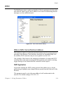
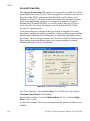
Figure 2-29 Assured Forwarding dialog
For Class 1 through 3, set the Service Rate (0 to Tx Data Rate, bps) and the
Maximum Queue Depth (1500-64000).
Specify the Precedence Levels for Medium Drop (20-90, % full) and High
Drop (10-80, % full).
Assured Forwarding Class 4 is pre-configured and the parameter fields are not
editable.
2-44
S L M - 5 6 5 0 A P a r a m et e r E d i t o r U s e r G u id e
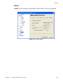
WAN
Default
Default is pre-configured; the parameter fields for this Class are not editable.
Figure 2-30 Default dialog
C h ap t e r 2 - U s i n g P a r a m e t e r E di t o r
2-45
NTP
NTP
The Network Time Protocol (NTP) settings are configured by clicking on the
NTP menu item (figure 2-31).
Figure 2-31 Network Time Protocol dialog
To automatically synchronize with the Internet time, activate the check box for
Enable NTP Server, then enter the NTP Address and the Time Zone for the
modem location.
2-46
S L M - 5 6 5 0 A P a r a m et e r E d i t o r U s e r G u id e
E v en t L o g
Event Log
Click on the Event Log menu item to access the logging level selection.
(figure 2-32).
Figure 2-32 Event Log dialog
The Enable selection triggers the logging mechanism for the NP Interface only.
It functions as a monitoring/troubleshooting aid to help determine the health of
the interface, as well as troubleshoot any issues found in the field. By enabling
the logging and setting the Level, system events are stored and reviewable
through the NP Web interface.
C h ap t e r 2 - U s i n g P a r a m e t e r E di t o r
2-47
I d e nt i f i c a t i o n
Identification
Click on the Identification menu item to display the current modem information that provides reference data for performing an upgrade (figure 2-33).
Figure 2-33 Identification dialog
The fields in this dialog are display only and cannot be edited.
2-48
S L M - 5 6 5 0 A P a r a m et e r E d i t o r U s e r G u id e
APPENDIX
GLOSSARY
A
ACK
A signal used in computing and other fields to indicate acknowledgement, such
as a packet message used in TCP to acknowledge the receipt of a packet.
ARP
Address Resolution Protocol – A protocol for a LAN device to determine the
MAC address of a locally connected device given its IP address. See also MAC.
ASR
Automatic Switch Request – A switch request message generated by older
Vipersat modems (e.g., CDM-570/L) that is sent to the VMS to establish a new
satellite link or adjust bandwidth between source and destination IP addresses.
B
Base
Modem
The main component in a satellite communications modem that consists of a
circuit board with the modem hardware and firmware and the associated interfaces.
BER
Bit Error Rate (sometimes Ratio) – A measure of the number of data bits
received incorrectly compared to the total number of bits transmitted.
BPS
Bits Per Second – A measure of transmission speed. See also Kb/s & Mb/s.
Appendix A - Glossary
A-1
BPSK
Binary Phase Shift Keying – A digital modulation technique in which the
carrier is phase shifted +/-180 degrees (two phases). The most robust of all
PSKs, but unsuitable for high data-rate applications when bandwidth is limited
due to encoding just one bit per symbol.
BUC
Block Up Converter – An upconverter so called because it converts a whole
band or “block” of frequencies to a higher band. The IF is converted to final
transmit frequency for satellite communications. The BUC is part of the satellite
ODU/transceiver.
C
C-Band
A frequency band commonly used for satellite communications (and sometimes
terrestrial microwave). For terrestrial earth stations, the receive frequency band
is 3.7–4.2 GHz and the transmit band is 5.925–6.425 GHz. See also Ku-band.
CDD
Comtech Data Demodulator
CDM
Comtech Data Modem
CIR
Committed Information Rate – The guaranteed minimum bandwidth assigned
to a remote terminal.
CLI
Command Line Interface – A mechanism for interacting with a computer operating system or software by typing commands to perform specific tasks.
Codecast
A network coding based ad hoc multicast protocol well-suited for multimedia
applications with low-loss, low-latency constraints. Because data is streamed
with no verification, high delivery ratios are obtained with very low overhead.
CRC
Cyclic Redundancy Check – A method of applying a checksum to a block of
data to determine if any errors occurred during transmission over communications links.
CXR
Carrier – A radio frequency transmission linking points and over which information may be carried.
D
DAMA
dBm
A-2
Demand Assigned Multiple Access – A process whereby communications links
are only activated when there is an actual demand.
Decibel referenced to 1 milliwatt.
S L M - 5 6 5 0 A P a r a m et e r E d i t o r U s e r G u id e
DES
Data Encryption Standard – A federal standard method for encrypting information for secure transmission. The Vipersat system offers 3xDES (Triple DES)
for encrypting traffic.
DHCP
Dynamic Host Configuration Protocol – An Internet protocol for automating
the configuration of computers that use TCP/IP.
DLL
Dynamic Link Library – The implementation of the shared library concept in
the Microsoft Windows system.
Downstream
DPC
DSCP
In the direction of the network Remote site(s).
Dynamic Power Control
Differentiated Services Code Point – The 6-bit field in an IP packet header that
is used for packet classification purposes and is the portion of ToS that is
detected by Vipersat modems.
DVB
Digital Video Broadcast
DVP
Digital Voice Processor – Used in packet voice applications.
E
Eb/No
Eb/No is the ratio of Eb (energy per bit) and No (noise power density per Hz).
The bit error rate (BER) for digital data is a decreasing function of this ratio. Eb
is the energy of an information bit measured in Joules or, equivalently, in Watts
per Hertz.
F
FAST Code
FEC
Flash
Fully Accessible System Topology Code – Designation for feature code used
by Comtech EF Data for their satellite modems. The FAST method makes it
easy to quickly upgrade the feature options of a modem while it is running live
in the network, either on site or remotely.
Forward Error Correction – A process whereby data being transmitted over a
communications link can have error correction bits added which may be used at
the receiving end to determine/correct any transmission errors which may occur.
Non-volatile computer memory that can be electrically erased and reprogrammed.
Appendix A - Glossary
A-3
Forward
Path
FTP
Transmission path from the Hub site to a Remote site.
File Transfer Protocol – An application for transferring computer files over the
Internet. See also TFTP.
G
G.729
GIR
Group ID
GUI
ITU standard for LD-CELP (Low Delay – Code Excited Linear Prediction)
voice encoding at 8 kb/s.
Guaranteed Information Rate
A number assigned to equipment which defines it as a member of a group when
addressed by the VMS burst controller.
Graphical User Interface – A form of graphical shell or user interface to a
computer operating system or software application.
H
H.323
A protocol standard for multimedia communications designed to support realtime transfer of audio (such as voice over IP) and video data over packet
networks. Quality of Service is a key feature of H.323. An alternative to SIP.
HDLC
High-Level Data Link Control – A standard defining how data may be transmitted down a synchronous serial link.
HPA
High Power Amplifier – The amplifier used in satellite communications to raise
the transmit signal to the correct power level prior to transmission to satellite.
HTTP
Hub
A-4
Hyper Text Transfer Protocol – The Internet standard for World Wide Web
(WWW) operation.
The central site of a network which links to a number of satellite earth sites
(remotes).
S L M - 5 6 5 0 A P a r a m et e r E d i t o r U s e r G u id e
I
ICMP
IDU
IF
Internet Control Message Protocol
Indoor Unit – In a VSAT system, the satellite modem is referred to as the IDU.
Intermediate Frequency – In satellite systems, IF frequencies are usually
centered around 70 or 140 MHz (video/TV), or 1200 MHz (L-band).
IFL
Intra-Facility Link – The coaxial cabling used to connect the satellite ODU to
the IDU. Carries the inbound and the outbound signals, and the 24 VDC for the
LNB.
Image
A binary firmware file that provides the operational code for the processor(s) in
a network unit.
IP
Internet Protocol – A format for data packets used on networks accessing the
Internet.
ISP
Internet Service Provider – A company providing Internet access.
ITU
International Telecommunications Union
K
Kb/s
Ku-Band
Kilo bits per second – 1000 bits/second. A measure of transmission speed. See
also bps & Mb/s.
A frequency band used for satellite communications. For terrestrial earth
stations the receive frequency band is in the range 10.95–12.75 GHz and the
transmit frequency band is 13.75–14.5 GHz. See also C-band.
L
L-Band
A frequency band commonly used as an IF for satellite systems using block up/
down conversion. Typically 950–1450 MHz Rx, 1250–1750 MHz Tx.
LAN
Local Area Network
LLA
Low Latency Application
LNA
Low Noise Amplifier – An amplifier with very low noise temperature used as
the first amplifier in the receive chain of a satellite system.
Appendix A - Glossary
A-5
LNB
Low Noise Block – A downconvertor so called because it converts a whole
band or “block” of frequencies to a lower band. The LNB (similar to an LNA) is
part of the satellite ODU/transceiver..
LNC
Low Noise Converter – A combined low noise amplifier and block down
converter, typically with an L-band IF.
LO
Local Oscillator – Component used in upconverters, downconverters, and transponders for frequency translation (heterodyne) of the carrier signal.
M
M&C
Monitor & Control
MAC
Media Access Control – A protocol controlling access to the physical layer of
an Ethernet network.
Mb/s
Mega Bits per Second – 1 Million bits/second. A measure of transmission
speed. See also bps & kb/s.
Modem
Modulator and demodulator units combined.
Multicast
Transmitting a single message simultaneously to multiple destinations (group)
on the IP network.
Multicommand
A command that allows multiple input choices in a single command execution.
N
A-6
NAT
Network Address Translation – An Internet standard that enables a LAN to use
one set of IP addresses for internal (private) traffic and a second set of addresses
for external (public) traffic.
NIC
Network Interface Controller – The network interface for a PC/workstation that
provides Ethernet connectivity. Depending on the computer, the NIC can either
be built into the motherboard, or be an expansion card. Some computers (e.g.,
servers) have multiple NICs, each identified by a unique IP address.
NMS
Network Management System
NOC
Network Operation Center – Has access to any earth station installed using the
VIPERSAT Management System (VMS). A NOC can remotely interrogate,
control, and log network activities.
S L M - 5 6 5 0 A P a r a m et e r E d i t o r U s e r G u id e
NP
Network Processor
O
ODU
Outdoor Unit – In a VSAT system, the RF components (transceiver) are usually
installed outdoors on the antenna structure itself and are thus referred to as an
ODU. The ODU typically includes the BUC and LNB, and is connected to the
IDU/modem by the IFL cabling.
OSPF
Open Shortest Path First – An open standard interior gateway routing protocol
used to determine the best route for delivering the packets within an IP network.
OSPF routers use the Shortest Path First link state algorithm to calculate the
shortest path to each node in the network. The Vipersat OSPF feature in the
Comtech SLM-5650A modem/router provides for dynamic routing functionality.
P
PLDM
PSK
PSTN
Path Loss Data Message – A packet message that is sent by older Vipersat
modems (e.g., CDM-570/L) to the VMS every sixty seconds, providing status
update and operating parameter information.
Phase-Shift Keying – A digital modulation scheme that conveys data by changing the phase of a base reference signal, the carrier wave. Different PSKs are
used, depending on the data rate required. Examples are binary phase-shift
keying (BPSK or 2-PSK) which uses two phases, and quadrature phase-shift
keying (QPSK) which uses four phases.
Public Switched Telephone Network – The world’s public circuit-switched
telephone network, digital and analog, and includes mobile as well as land-line
voice and data communications.
Appendix A - Glossary
A-7
Q
QAM
Quadrature Amplitude Modulation – A digital modulation technique in which
the amplitude of two carrier waves is changed to represent the data signal. These
two waves are 90 degrees out of phase with each other.
QoS
Quality of Service
QPSK
Quadrature Phase-Shift Keying – A digital modulation technique in which the
carrier is phase shifted +/- 90 or +/-180 degrees. With four phases, QPSK can
encode two bits per symbol—twice the rate of BPSK. However, it also uses
twice the power. Also known as 4-PSK or 4-QAM.
R
Remote
Return Path
RF
RFC
RIP
ROSS
Transmission path from a Remote site to the Hub site.
Radio Frequency – A generic term for signals at frequencies above those used
for baseband or IF.
Request For Comment – The official publication channel for Internet standards
(such as communication protocols) issued by the Internet Engineering Task
Force (IETF).
Routing Information Protocol
Roaming Oceanic Satellite Server
RS-232
A common electrical/physical standard issued by the IEEE used for point to
point serial communications up to approximately 115 kb/s.
RTP
Real-time Transport Protocol – A standardized packet format for delivering
real-time applications such as audio and video over the Internet. Frequently
used in streaming media systems, videoconferencing, and VoIP.
Rx
A-8
Satellite earth site that links to a central network site (Hub).
Receive
S L M - 5 6 5 0 A P a r a m et e r E d i t o r U s e r G u id e
S
SCPC
Single Channel Per Carrier – A satellite communications technique where an
individual channel is transmitted to the designated carrier frequency. Some
applications use SCPC instead of burst transmissions because they require guaranteed, unrestricted bandwidth.
SIP
Session Initiation Protocol – A general purpose protocol for multimedia
communications, commonly used for voice over IP (VoIP) signaling. An alternative to the H.323 protocol.
SNG
Satellite News Gathering – A satellite uplink van/truck with television crew on
location conducting a live report for a newscast.
SNMP
Simple Network Management Protocol – A protocol defining how devices from
different vendors may be managed using a common network management
system.
SOTM
Satellite On-The-Move – The ability of a mobile remote terminal to roam
across satellite beams to preserve link integrity and to automatically connect
from one satellite and/or hub to another in a global network.
Star
Topology
A network topology which, if drawn as a logical representation, resembles a star
with a hub at the center.
STDMA
Selective Time Division Multiple Access – A multiple access technique where
users time-share access to a common channel with variable-sized time slots
allocated on usage.
Streamload
Protocol
SUM
A proprietary Vipersat data streaming protocol.
Status Update Message – A packet message that is sent by newer Vipersat
modems (e.g., SLM-5650A) to the VMS every sixty seconds, providing status
update and operating parameter information.
T
TCP/IP
TDM
Transmission Control Protocol / Internet Protocol – A standard for networking
over unreliable transmission paths. See also UDP.
Time Division Multiplexing – A method of multiplexing that provides the
transmission of two or more signals on the same communication path or channel, but at different times by utilizing recurrent timeslots.
Appendix A - Glossary
A-9
TFTP
ToS
Tx
Trivial File Transfer Protocol – A simple file transfer protocol used over reliable transmission paths. See also FTP.
Type of Service
Transmit
U
UDP
UDP
multicast
Unicast
Upstream
User Datagram Protocol – A standard for networking over reliable transmission
paths.
A multicast transmission using the UDP protocol.
Transmitting information/data packets to a single destination on the IP network.
In the direction of the network Hub site.
V
VESP
Vipersat External Switching Protocol – A switch-request protocol that allows
external VPN equipment and Real-time proprietary applications to negotiate
bandwidth requests between any two subnets on a Vipersat network. VESP is
used by newer Vipersat modems (e.g., SLM-5650A) to send a switch request to
the VMS to establish a new satellite link or adjust bandwidth for an existing
link.
VCS
Vipersat Circuit Scheduler – A proprietary satellite communication scheduling
system used to schedule Vipersat network resources in support of a variety of
high-priority applications such as video conferencing and scheduled broadcasting.
VFS
Vipersat File Streamer – A file transfer application utilizing UDP and a proprietary Streamload protocol to transmit data across the Vipersat network.
VLoad
Vipersat Load Utility – A comprehensive tool for managing and distributing
application, configuration, and identification information for the modem/routers
in Vipersat satellite networks.
VMS
A-10
Vipersat Management System – A comprehensive M&C tool providing rapid
and responsive control of Vipersat satellite networks. Comprised of client and
server components.
S L M - 5 6 5 0 A P a r a m et e r E d i t o r U s e r G u id e
VNO
Virtual Network Operator – A provider of management services that does not
own the telecommunication infrastructure. The Comtech Vipersat Network
Products’ VNO solution allows satellite space segment operators to selectively
expose resources in their satellite network to other service providers, customers,
or partners.
VoIP
Voice over IP – The routing of voice communications over the Internet or
through any IP-based network.
VOS
Vipersat Object Service – The main software service of the VMS application.
W
Wizard
A specialized program which performs a specific function, such as installing an
application.
WRED
Weighted Random Early Detection – A queue management algorithm with
congestion avoidance capabilities and packet classification (QoS) providing
prioritization.
Appendix A - Glossary
A-11
{ This Page is Intentionally Blank }
A-12
S L M - 5 6 5 0 A P a r a m et e r E d i t o r U s e r G u id e
INDEX
CHAPTER 0
A
address resolution protocol, 2-37
allocation, 2-19
method, 2-9
area, 2-32
ARP, 2-37
add translation, 2-37
IP address, 2-37
MAC address, 2-37
assured forwarding, 2-44
drop precedence, 2-44
authentication key, 2-34
B
bandwidth allocation
dynamic cycle, 2-9, 2-10
dynamic slot, 2-9, 2-10
entry channel, 2-10, 2-11
fixed, 2-10
GIR, 2-9, 2-11
burst controller, 2-14, 2-24
burst map multicast address, 2-14
C
calibration, 2-24
max
coding rate, 2-24
data rate, 2-24
modulation, 2-24
class selector 6, 2-42
configuration alert, 2-3
contact information, 1-4
conventions and references, 1-2
cost, 2-33
customer support, 1-4
cycles per map, 2-12, 2-13
D
dead interval, 2-33
default, 2-45
demod, 2-27
DiffServ Code Point, 2-40
assured forwarding, 2-40, 2-44
drop precedence, 2-44
class selector 6, 2-40, 2-42
default, 2-40, 2-45
expedited forwarding, 2-40, 2-43
max queue depth, 2-40, 2-41
per-hop behavior, 2-40
service rate, 2-40, 2-41
DLL files, 2-1
updating, 2-2
DPC, 2-22
calibration, 2-24
max coding rate, 2-24
max data rate, 2-24
max modulation, 2-24
enable dynamic power control, 2-23
margin, 2-24
maximum power, 2-24
outbound IP address, 2-14
speed-up Eb/N0 range, 2-23
target
Eb/N0, 2-24
IP address, 2-23
drop precedence level, 2-44
DSCP, 2-40
per-hop behavior, 2-40
dynamic
cycle, 2-9, 2-10
link library, 2-1
power control, 2-22
slot, 2-9, 2-10
E
Eb/N0, 2-22, 2-23, 2-24
ECM, 2-11
enable
dynamic power control, 2-23
flow control, 2-35
home state, 2-25
load switching, 2-17
Index-1
management security, 2-36
NTP server, 2-46
OSPF, 2-32
proxy ARP, 2-35
quality of service, 2-40
remote removal, 2-16
STDMA, 2-9
entry channel, 2-10, 2-11
event log, 2-47
excess capacity, 2-20
expedited forwarding, 2-43
F
features, 1-3
fixed mode, 2-10
flow control, 2-35
G
general, 1-1
GIR, 2-9, 2-11
glossary, 1-1, A-1
group ID, 2-12
guaranteed information rate, 2-9, 2-11
guard band, 2-13
H
hello interval, 2-33
home state, 2-25
demod, 2-27
enable home state, 2-25
mod, 2-26
modem group command, 2-26
how to use this manual, 1-1
I
identification, 2-48
IP address mode, 2-36
L
LAN, 2-35
ARP, 2-37
enable flow control, 2-35
enable management security, 2-36
enable proxy ARP, 2-35
Index-2
IP address mode, 2-36
local IP address, 2-36
management IP address, 2-36
port
base, 2-36
VLAN, 2-36
local area network, 2-35
M
management security, 2-36
margin, 2-24
max
coding rate, 2-24
data rate, 2-24
modulation, 2-24
maximum
power, 2-24
queue depth, 2-41
menu item
ARP, 2-37
assured forwarding, 2-44
calibration, 2-24
class selector 6, 2-42
default, 2-45
demod, 2-27
Diff Serv, 2-40
DPC, 2-22
event log, 2-47
expedited forwarding, 2-43
home state, 2-25
identification, 2-48
LAN, 2-35
mod, 2-26
NTP, 2-46
OSPF, 2-31
remote list, 2-14
remote removal, 2-16
routing, 2-29
STDMA, 2-8
switching, 2-17
ToS, 2-20
Vipersat, 2-7
WAN, 2-39
working mode, 2-5
message digest key, 2-34
SLM-5650A Parameter Editor User Guide
mod, 2-26
modem group command, 2-26
multicast management address, 2-7
N
network
function, 2-5
ID, 2-7, 2-12
role, 2-5, 2-14, 2-16, 2-20, 2-29, 2-31
time protocol, 2-46
enable NTP server, 2-46
network address, 2-32
NTP, 2-46
address, 2-46
enable NTP server, 2-46
time zone, 2-46
O
OSPF, 2-31, 2-39
area, 2-32
authentication key, 2-34
cost, 2-33
dead interval, 2-33
enable OSPF, 2-32
hello interval, 2-33
message digest key, 2-34
network address, 2-32
priority, 2-33
retransmit interval, 2-32
topology, 2-33
transmit delay, 2-33
outbound IP address, 2-14
P
param file, 1-3
parameter editor
features, 1-3
general, 1-1
using, 1-1
per-hop behavior, 2-40
port
base, 2-36
VLAN, 2-36
preamble, 2-13
priority, 2-33
product description, 1-3
proxy ARP, 2-35
Q
QoS, 2-39
quality of service, 2-39, 2-40
enable, 2-40
R
remote
list, 2-14
add remote, 2-14
removal, 2-16
cycles, 2-16
enable, 2-16
retry, 2-17
retransmit interval, 2-32
role designation, 2-5
routing, 2-29
OSPF, 2-31, 2-39
static routes, 2-29
S
saving changes, 2-2
service rate, 2-41
slot
capacity, 2-18
data length, 2-12
speed-up Eb/N0 range, 2-23
static routes, 2-29
add route, 2-30
description, 2-31
destination address, 2-31
HDLC address, 2-31
interface, 2-31
next hop, 2-31
stats collection, 2-13
STDMA, 2-8, 2-10, 2-13, 2-14
ACK, 2-11
allocation method, 2-9
buffers, 2-13
burst controller, 2-14, 2-24
burst map multicast address, 2-14
Index-3
calculator, 2-13
controller, 2-11
cycle, 2-12
cycles per map, 2-12
data rates, 2-11
enable STDMA, 2-9
group, 2-12, 2-14, 2-16
ID, 2-12
guard band, 2-13
mode, 2-9, 2-15, 2-22
dynamic cycle, 2-9, 2-10
dynamic slot, 2-9, 2-10
entry channel, 2-10, 2-11
fixed, 2-10
GIR, 2-9, 2-11
outbound IP address, 2-14
preamble, 2-13
remote list, 2-14
add remote, 2-14
remote removal, 2-16
cycles, 2-16
enable, 2-16
retry, 2-17
slot data length, 2-12
stats collection, 2-13
step
delay, 2-20
down threshold, 2-19
up threshold, 2-19
switch delay, 2-19
switching, 2-17
allocation, 2-19
enable load switching, 2-17
excess capacity, 2-20
slot capacity, 2-18
step delay, 2-20
step down threshold, 2-19
step up threshold, 2-19
switch delay, 2-19
ToS, 2-20
Index-4
T
target
Eb/N0, 2-24
IP address, 2-23
TDM outbound, 2-14
topology, 2-33
ToS, 2-20
identifier, 2-21
name, 2-21
switch
rate, 2-21
type, 2-21
timeout, 2-21
transmit delay, 2-33
tree menu, 2-3
type of service, 2-20
U
unit name, 2-7
using, 1-1
V
Vipersat, 2-7
DPC, 2-22
home state, 2-25
multicast management address, 2-7
network ID, 2-7
STDMA, 2-8
switching, 2-17
unit name, 2-7
VLoad, 1-3, 2-1
user guide, 1-2
VMS, 1-3, 2-1
user guide, 1-2
W
WAN, 2-39
internal multicast address, 2-39
quality of service, 2-39
working mode, 2-3, 2-5
SLM-5650A Parameter Editor User Guide