1
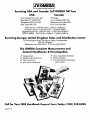
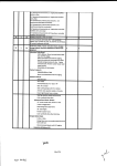
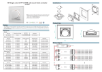
BL RG-2501 Series
@m Tipping Bucket Rain Gauge
.a OMEGx] Operator’s Manual
b An OMEGA
Technologies Company
I
Servicing USA and Canada: Call OMEGA Toll Free
USA
One Omega Drive, Box 4047
Stamford, CT 06907-0047
Telephone: (203) 359-1660
FAX: (203) 359-7700
Canada
976 Bergar
Lava1 (Quebec) H7L 5Al
Telephone: (514) 856-6928
FAX: (514) 856-6886
Sales Service: l-800-826-6342 / l-800-TC-OMEGASM
Customer Service: l-800-622-2378 / l-800-622-BESTSM
Engineering Service: l-800-872-9436 / l-800-USA-WHENSM
TELEX: 996404 EASYLINK: 62968934 CABLE: OMEGA
Servicing Europe: United Kingdom Sales and Distribution Center
25 Swannington Road, Broughton Astley, Leicestershire
LE9 6TU, England
Telephone: 44 (1455) 285520 FAX: 44 (1455) 283912
The OMEGA Complete Measurement and
Control Handbooks & Encyclopedias
Y* Temperature
t, Pressure, Strain & Force
u* Flow and Level
Yr pH and Conductivity
V Data Acquisition Systems
I/ Electric Heaters
V Environmental Monitoring
and Control
Call for Your FREE Handbook Request Form Today: (203) 3591RUSH
MSS0395FvR18
Unpacking Instructions
w
Remove the Packing List and verify that you have received all equipment, including the following
(quantities in parentheses):
RG-2501 Tipping Bucket Rain Gauge (1)
Operator’s Manual (1)
If you have any questions about the shipment, please call the OMEGA Customer Service
Department.
When you receive the shipment, inspect the container and equipment for signs of damage. Note
any evidence of rough handling in transit. Immediately report any damage to the shipping agent.
The carrier will not honor damage claims
unless all shipping material is saved for
inspection. After examining and removing contents, save packing material and
carton in the event reshipment is necessary.
TABLE OF CONTENTS
Chapter 1 Introduction .........................................
1.1 General Description ....................................
1.2 Specifications ........................................
1
1
2
Chapter 2 Installation ..........................................
2.1 Site Requirements .....................................
2.2 Installation ..........................................
2
2
3
Chapter 3 Operation
. . . . . . . . . . . . . . . . . . . . . . . . . . . . . . . . . . . . . . . . . . .3
Chapter 4 Calibration ..........................................
Table of Standard Calibration Quantities ..........................
Chapter 5 Maintenance
Chapter 6 Troubleshooting
. . . . . . . . . . . . . . . . . . . . . . . . . . . . . . . . . . . . . , , . . 5
. . . . . . . . . . . . . . . . . . . . . , . . . . . . . . . . . . . . . . .6
4
5
Chapter 1: Introduction
1.1 General Description
The OMEGA@ Model RG-2501 Tipping Bucket Rain Gauge provides an inexpensive yet
accurate method for measuring and recording rainfall. The tipping bucket design provides a
means for operating an magnet-sensitive switch. The switch contact closure may be used with
electro-mechanical counters, event recorders or electronic recording equipment to
automatically obtain a record of the rainfall. The standard model of the rain gauge, Model
RG-2501, produces a switch closure for each 0.01 inch of rainfall. The Model RG-2501M
switch closure represents 1 millimeter of rainfall. Other calibrations of the rain gauge are
available upon request. The tipping bucket design allows unlimited measurements since the
tipping action dumps the water out of the bucket on alternating tips. Drain holes in the base
plate allow the water to drain out of the gauge.
All OMEGA@ rain gauges are made of the highest quality materials to provide long term,
trouble free operation with a minimum of maintenance as long as each gauge has been
properly installed and maintained. Parts of the rain gauge are made of aluminum with
anodized or painted finishes. Fasteners are all stainless steel except for the aluminum pop
rivets used to hold the bug screens in place. Some components are made of plastic, including
the terminal block, the signal cable strain relief, the calibration screw acorn nuts, the bearing
spacers, and the bearing inserts.
The basic rain gauge assembly includes a removable outer funnel, the tipping bucket
assembly, the magnet and switch assemblies, and the outer housing assembly. The main
sensor assembly with the tipping buckets, switch, magnet and signal terminal block is
mounted onto a bracket that is fastened to the base plate. Two adjustable screws provide the
calibration of the buckets by changing the position of the bucket stop point.
Three adjustable legs allow the gauge to be fastened permanently onto a platform or deck
using standard fasteners. Slots in the legs provide some adjustment for leveling the gauge. A
two-conductor, shielded cable with a wire size between 18 and 24 AWG should be used to
connect the rain gauge output into the monitoring or recording equipment. A two position
terminal block is provided for attaching the cable into the switch. Power for operating the
switch originates within the monitoring/recording equipment and is typically a pulse ranging
from 5 to 12 VDC.
The Model RG-2501 and RG-2501M rain gauges are not available in heated versions for use
in cold climates. These two gauges are designed and sold as low cost general purpose rain
NovaLynx
gauges and are best suited for standard rainfall measurements only. Refer to the
catalog or contact the company to obtain information regarding other types of rain gauges
that are available for more specialized uses.
1
1.2 Specifications
Capacity: unlimited
Orifice: 8” (20 cm) diameter
Calibration: O.Ol”, 1 mm, 0.5 mm, 0.25 mm
Accuracy: + 4% for rainfall rates of 1” to 6 ” per hour
Switch: magnetic sensitive, 3 W, 28 Vat
Construction:
Fabricated parts: anodized aluminum
Fasteners: stainless steel (except for aluminum rivets)
Mounting: 3 legs, l/4” diameter bolt holes on a 9-l/2” diameter bolt circle
Dimensions: 8.4” D x 15 ” H
Shipping weight: 8 lbs
Optional Accessories:
Wind Screen, Alter Type
Event Recorder, Drum Chart
Calibrator Bottle
Digital Event Counter
Model RG-952
Model RG-952
Model RG-2596
Model RG-2596
Chapter 2: Installation
2.1 Site Requirements
Finding the best possible site for the gauge is important and careful consideration should be
given to the quality of precipitation catch prior to the final installation. The most accurate
rainfall measurements are made in sheltered areas that block wind and eddy currents in the
vicinity of the gauge. The best exposures are often found in orchards or openings within a
grove of trees, bushes, or shrubbery. Fences or other objects can act together to serve as an
effective windbreak. As a general rule in such areas, the heights of the objects and the
distance from the gauge should be uniform. The height of nearby objects above the gauge
should not exceed about twice their distance from the gauge. Individual or small groups of
isolated objects near a gauge may set up serious eddy currents. Since it is not always possible
to select sites that provide adequate protection from adverse wind effects, an open site away
from isolated objects may be the only location available. Wind Shields help minimize loss of
precipitation catch by breaking up the air flow immediately over the gauge funnel. Wind
effects on catch losses are much greater during snowfall than rainfall. Windshields are not
generally installed at gauge site locations where snowfall constitutes less than 20% of the
mean annual precipitation.
Good exposures are not always permanent. The growth of vegetation, trees, and shrubs can
change an excellent exposure into an unsatisfactory one within a relatively short time. Sites
should be inspected and groomed regularly.
2
In areas where heavy snowfall occurs, rain and snow gauges are mounted onto supports
(tower) at a height well above the average snow level. A location with this type of exposure
would be improved if the tower can be located within an area of trees of comparable height.
2.2 Installation
The RG-2501 rain gauge may be shipped from the factory with the three mounting legs
attached upside down on the l/4-20 bolts. If this is the case, detach and replace the legs into
the correct position with the legs pointing downward and the leg end facing outward, away
from the gauge. (Refer to the assembly drawing.) Be sure the leg mounting bolts are tightly
fastened. Carefully remove all packing material and any tape, foam pieces, or rubber bands
used to keep the tipping bucket from moving during shipment. Operate the tipping bucket to
verify that the bucket can now move freely.
Place the funnel into the top of the gauge. The gauge housing must be mounted as level as
l/4” diameter mounting
possible on its platform. The holes in the mounting legs are sized for
bolts. For correct measurement of precipitation, the open end edge of the rain gauge funnel
must lie in a horizontal plane. This can be tested by laying a carpenter ’s level across the top
edge of the gauge funnel using two 90 ” directions: one direction crossing the other at right
angles. If the top is not level in both directions, the condition should be corrected. Washers
can be used as leveling shims between the mounting legs on the gauge and the platform or
tower mounting plate.
Place the bug and debris screens into place inside the funnel.
Upon completion of the rain gauge mounting, route the signal cable to the
monitoring/recording equipment. Use the most direct route possible, avoiding sharp or
jagged objects that may rub against the cable jacket during high winds causing exposure of
the wires. Attach the cable to the structure or support using plastic wire ties or other
appropriate devices. When using plastic wire ties, use only black, ultraviolet resistant, wire
ties, placing them at a spacing of two to three feet along the cable length. for best results,
whenever possible, the signal cable should be routed through conduit.
Chapter 3: Operation
Precipitation entering the collection orifice fills the calibrated tipping bucket assembly. When
the calibrated amount has been collected, the bucket tips, causing a momentary closure of the
reed switch, and sending an electrical signal to the event recorder or other data collection
device. The precipitation sample is discharged out of the gauge at the same time.
3
Chapter 4: Calibration
The rain gauge is calibrated at the factory. Recalibration should not be necessary unless
damage during shipment or mishandling during installation has occurred. If the damage is
extensive, the gauge may need to be repaired or replaced before it can be used properly.
Verify the calibration by using a calibration bottle, a graduated cylinder, or a calibrated
burette. The calibration is verified by allowing a known volume of water to flow into the
funnel at a rate of 1 to 2 inches per hour producing a specific number of bucket tips. Before
putting the volume of water into the funnel run some water into the gauge to wet the funnel
and the buckets. The gauge calibration test must be made while the gauge is wet. Do not
’
wipe off any water especially from the buckets between tests and calibration screw
adjustments. Add the measured amount of water at the specified flow rate (refer to Table 1
The bucket should tip within the published gauge tolerances and should give the calculated
number of tips within the gauge accuracy. If the number of counts is not within the gauge
accuracy, then the bucket stops must be adjusted to increase or to decrease the amount of
water needed to tip the buckets.
The individual buckets can be calibrated by placing an amount of water equal to one tip into
the bucket and adjusting the bucket stop on the opposite side of the gauge until the bucket
tips and empties its water. To move the bucket stop screw first loosen the hex nut on the
outside of the rain gauge. The nut keeps the screw locked into place. With the nut loosened,
the screw can be rotated by hand or by using a screw driver set into the head of the screw.
The screw should only be rotated by a small amount between each test. Use a large rotation
of the screw only if the bucket is out of calibration by a large number of counts.
Note that moving the bucket stop screw upward means that less water is needed to tip the
bucket and moving the screw downward increases the amount of water needed to tip the
bucket.
For inches of rain, the amount of water needed for a single tip equal to 0.01 inches is 8.24
milliliters. For a 1 millimeter tip the amount of water is 32.43 milliliters. Add the amount of
water needed to each of the buckets separately and adjust the corresponding stop screws as
needed to obtain a single tip form each bucket. Several adjustments of each calibration screw
may be necessary as there will be some influence from each of the buckets upon the other as
the adjustments are changed. If there is repeatability in the tip with the calibrated amount of
water, then the adjustment screw has been correctly set and can be locked into place. Use the
hex nut located on the adjustment screw at the outside the rain gauge base to lock the screw
into position. Take care and do not allow the screw to rotate as the nut is being tightened. In
case the screw has turned slightly, retest the tip of the bucket after the nut has been
tightened.
4
).
Table 1 - Standard Calibration Quantities
260-2501M @ 1 mm (std)
Cal:
32.43
260-2501M @ .5 mm
Cal:
16.215 milliliters
260-2501 @ .Ol” (std)
Cal:
260-2501 @ .05”
Cal:
8.24
41.2
s
milliliters
milliliters
milliliters
Flow rate for calibration: l/2 ml per second.
Accuracy desired is & 4% of volume at 1-6 inches
precipitation per hour.
After making changes to the bucket stop screws, retest the rain gauge operation using the
calibration bottle and a large volume of water to produce 50 to 100 tips at a rate of 1 to 2
inches per hour. Remember to thoroughly wet the funnel and buckets first!
The total number of tips generated should correspond to the volume of water run through the
gauge (expressed in milliliters; 1 quart = 946.3 milliliters) divided by the calibration
quantity indicated in milliliters in Table 1. A tolerance of + 6% or better should be obtained
through testing using this method. A more accurate test can be made in the lab using
controlled conditions and more accurate test equipment.
Chapter 5: Maintenance
Rain gauges require regular maintenance. Gauges located in heavily forested areas or where
airborne debris is a consideration should be serviced more often. The bucket assembly and
drain screens should be inspected to ensure they are clean and free from debris such as
leaves and insects. The tipping buckets should be carefully wiped clean to remove mud and
dirt. Inspect the small tube of the main funnel and remove any obstructions inside it.
Test the gauge for correct operation and accuracy of the tipping buckets. Refer to Section 4.
Annually or after 6 months of heavy operation, put a drop of light machine oil onto each
rotating part, specifically, the bucket assembly shaft at the bearings.
Should the tipping bucket fail to rotate freely about its axis, check the two small right angled
brackets that hold the shaft and the bearings onto the main mounting bracket. These two
brackets can become loosened or misaligned causing the shaft to bind. The brackets
’ edges
should be at the same level.
Severe friction will create excessive wear in the plastic bushings resulting in the magnet
making contact with the switch and stopping the bucket assembly from tipping. Replace worn
5
or damaged bushings. Too many bushings may cause the bucket shaft to bind as well. If a
bushing needs to be removed, remove it from the side away from the magnet and switch
allowing more room between the magnet and switch. The number of bushings will vary from
gauge to gauge depending upon variations in the materials used. Typically there are four
bushings on each side of the shaft.
Check the magnetic switch for proper operation. The standard switch closure is a momentary
single pole, normally open (SPNO) contact. Connect an ohmmeter to the gauge at the signal
cable terminal strip. With the bucket assembly at rest upon one of the calibration screws, the
ohmmeter should read infinite resistance. Slowly move the bucket assembly to simulate a rain
event until the bucket assembly has fully rotated. As the magnet passes over the end of the
barrel switch, the resistance of the switch should change to a short (zero or less than
one ohm). As the tipping bucket comes to a complete tip and rests upon the other calibration
screw the ohmmeter will again read an infinite resistance.
Upon completion of all testing and maintenance, replace the funnel into the gauge housing.
Confirm that the gauge is still level by checking as described in Section 2.3.
In order to maintain the accuracy of the rainfall catch, the rim of the funnel should be
protected from dents or other damage that might alter its shape.
Chapter 6: Troubleshooting
If it becomes necessary to correct an operation problem always perform the following step
first: Check the cable connections to ensure a solid connection. A loose or faulty cable is
often the problem to missing data. Next, check to see that the bucket assembly moves freely
upon its pivoting shaft. Make sure that the magnet has not become loose and is securely in
place on the bucket. Check to ensure proper contact closure. Refer to Section 5.4.
If the gauge registers low or not at all during a precipitation event, check for debris in the
inlet funnel and drains that might be blocking bucket movement. If the gauge registers high
during precipitation, check the level bubble indicator to ensure the sensor is properly
installed and leveled. Recheck calibration.
Whenever the gauge is to be used with an electro-mechanical counter or event recorder,
surge protection diodes must be installed between the gauge and the equipment. Failure to
install these diodes will result in a stuck magnetic switch due to electrical interference from
the counter or recorder solenoids. Some gauges have been shipped with these diodes installed
across the signal terminal block inside the gauge. If it appears that the diodes have not been
included on your gauge and that they will be needed for your application, please contact
OMEGA@ and arrange to have a set of diodes sent, one set per gauge.
6
d
i
\
c
I
4
a
I
’
r -----_
I
I
I
I
I
I
1
I
I
I
I
I
I
I
I
I
I
I
I
I
-
-
WIR
TO EVEN
OR
PROTECTION DIODE
OR
1 SKE27A
1.5KE27C (Xl )
ow
RAIN GAUG E
BARREL SWlTCt -I
1’1 TLE
ATTACH SURGE SUPPRESSION DIODE(S
TO RAIN GAUGE SWITCH OR TO INPU
OF RECORDER OR COUNTER
.
T
)
SCHEMATIC, R
SWITCH SURGE
MODEL
USAGE
DATE
260
,
SCALE D
l 3Y
I -
260 2501
-
8
&FULL
d
_
------- .G?
i
A
)
__
z
GE
AU
ZCTION A- A
NI G
RA,
LY
2501
-
MB
L 260 D
PARTS LIST FOR
TIPPING BUCKET RAIN GAGE
MODEL 260-2501
8 INCH ORIFICE, 0.01”PER TIP
EC0 980102
NL P/ N
DESCRIPTION
10000049
10000069
10000070
10000072
10000076
10000077
10000078
10000079
10000116
10000224
10000225
21051401
41500302
41900600
46311501
51001802
SCREEN, DRAIN
BRACKET, BUCKET SHAFT SUPPORT
BRACKET, BUCKET SUPPORT MOUNTING
LEG, RAIN GAGE SUPPORT
BODY ASSEMBLY, OUTER CASE
BRACKET, BARREL SWITCH
BUCKET WITH SHAFT ASSEMBLY
MAGNET WITH BRACKET ASSEMBLY
FUNNEL ASSEMBLY, 8 INCH
SCREEN, LOWER FUNNEL, 2 ” DIA
SCREEN, UPPER FUNNEL, 7
5/8” DIA
TERMINAL BLOCK, 2 PIN
STRAIN RELIEF, SIGNAL CABLE
SPADE LUG, #6 NYLON INSULATED
SURGE PROTECTION DIODE
1.5KE27C
BARREL SWITCH
BEARING, NYLON INSERT, PRESS FIT
SPACER/WASHER, NYLON 0.44 OD X 0.2 ID X 0.033 THK
SCREW 4-40 X l/4 FLAT HEAD SS
SCREW 4-40 X 3/8 PAN HEAD SS
WASHER, #4 LOCK SS
SCREW, 6-32 X 3/8 PAN HEAD SS
WASHER, #6 FLAT SS
WASHER, #6 LOCK SS
SCREW, lo-32 X l/2 PAN HEAD SS
SCREW, lo-32 X 3 PAN HEAD SS
NUT, #lO HEX SS
NUT, #lO ACORN, NYLON
WASHER, #lO FLAT SS
WASHER, #lO LOCK SS
RIVET, l/8 X l/4 ALUM
71010100
72310503
7206040 1
72083301
72341001
72082002
72302101
72341101
72188003
72083003
72211410
72246310
7230030 1
72340210
72380000
QTY
2
2
1
3
1
1
1
1
1
1
1
1
1
4
1
1
2
8
2
3
3
5
5
5
6
2
2
2
6
6
4
WARRANTY
OMEGA warrants this unit to be free of defects in materials and workmanship and to give satisfactory service for a period of 13 months from date of purchase. OMEGA Warranty adds an additional one (1) month grace period to the normal
one (1) year product warranty to cover handling
OMEGA ’s customers receive maximum coverage on each
and shipping time. This ensures that
product. If the unit should malfunction, it must be returned to the factory for evaluation. OMEGA ’s
(AR) number immediately upon
Customer Service Department will issue an Authorized Return
phone or written request. Upon examination by OMEGA, if the unit is found to be defective it will
be repaired or replaced at no charge. However, this WARRANTY is VOID
if the unit shows evidence
of having been tampered with or shows evidence of being damaged as a result
of excessive corrosion; or current, heat, moisture or vibration; improper specification; misapplication; misuse or
other operating conditions outside of OMEGA ’s control. Components which wear or which are
damaged by misuse are not warranted. These include contact points, fuses, and
triacs.
OMEGA is glad to offer suggestions on the use of its various products.
Nevertheless,
OMEGA only warrants that the pa
defects.
OMEGA MAKES NO OTHER WARRANTIES OR REPRESENTATIONS OF ANY KIND WHATSOEVER, EXPRESSED OR IMPLIED, EXCEPT THAT OF TITLE AND ALL IMPLIED WARRANTIES INCLUDING ANY WARRANTY OF MERCHANTABILITY AND FITNESS FOR A
PARTICULAR PURPOSE ARE HEREBY DISCLAIMED.
LIMITATION OF LIABILITY: The remedies of purchaser set forth herein are exclusive and
the total liability of OMEGA with respect to this order, whether based on contract, warranty, negligence, indemnification, strict liability or otherwise, shall not exceed the
purchase price of the component upon which liability is based. In no event shall
OMEGA be liable for consequential, incidental or special damages.
Every precaution for accuracy has been taken in the preparation of this manual; however, OMEGA
ENGINEERING, INC. neither assumes responsibility for any omissions or errors that may appear
nor assumes liability for any damages that result from the use of the products in accordance with
the information contained in the manual.
SPECIAL CONMTION: Should this equipment be used in or with any nuclear installation or activity,
purchaser will indemnify OMEGA and hold OMEGA harmless from any liability or damage whatsoever arising out of the use of the equipment in such a manner.
RETURN REQUESTS / INQUIRIES
Direct all warranty and repair requests/inquiries to the OMEGA ENGINEERING Customer Service
Department. BEFORE RETURNING ANY PRODUCT(S) TO OMEGA, PURCHASER MUST OBTAIN AN
AUTHORIZED RETURN (AR) NUMBER FROM OMEGA ’S CUSTOMER SERVICE DEPARTMENT (IN
ORDER TO AVOID PROCESSING DELAYS). The assigned AR number should then be marked on the
outside of the return package and on any correspondence.
FOR WARRANTY RETURNS, please have the
following information available BEFORE contacting OMEGA:
1. P.O. number under which the product was
PURCHASED,
2. Model and serial number of the product
under warranty, and
3. Repair instructions and/or specific problems relative to the product.
FOR NON-WARRANTY REPAIRS OR CALIBRATION, consult OMEGA for current repair/
calibration charges. Have the following information available BEFORE contacting OMEGA:
1. P.O. number to cover the COST of the
repair/calibration,
2. Model and serial number of product, and
3. Repair instructions and/or specific problems
relative to the product.
OMEGA’s policy is to make running changes, not model changes, whenever an improvement is possible. This affords
our customers the latest in technology and engineering.
OMEGA is a registered trademark of OMEGA ENGINEERING, INC.
(0 Copyright 1995 OMEGA ENGINEERING, INC. All rights reserved. This documentation may not be copied, photocopied,
reproduced, translated, or reduced to any electronic medium or machine-readable form, in whole or in part, without prior
written consent of OMEGA ENGINEERING, INC.
Where Do I Find Everything I Need for
Process Measurement and Control?
OMEGA...Of Course!
TEMPERATURE
m Thermocouple, RTD & Thermistor Probes, Connectors, Panels
& Assemblies
m Wire: Thermocouple, RTD & Thermistor
@ Calibrators & Ice Point References
@ Recorders, Controllers & Process Monitors
@ Infrared Pyrometers
PRESSURE/STRAIN FORCE
w Transducers & Strain Gages
& Load Cells & Pressure Gauges
& Displacement Transducers
m Instrumentation & Accessories
FLOW/ LEVEL
@ Rotameters, Gas Mass Flowmeters
& Flow Computers
@ Air Velocity Indicators
@’Turbine/Paddlewheel Systems
@’Totalizers & Batch Controllers
H/CONDUCTIVITY
& pH Electrodes, Testers & Accessories
@ Benchtop/Laboratory Meters
@’Controllers, Calibrators, Simulators & Pumps
m Industrial pH & Conductivity Equipment
DATA ACQUlSlTlON
@’
Data Acquisition and Engineering Software
m Communications-Based Acquisition Systems
m Plug-in Cards for Apple, IBM & Compatibles
& Datalogging Systems
@’Recorders, Printers & Plotters
HEATERS
@’Heating Cable
@’Cartridge & Strip Heaters
@’Immersion & Band Heaters
D Flexible Heaters
& Laboratory Heaters
ENVIRONMENTAL MONITORING AND CONTROL
@’Metering & Control Instrumentation
@’Refractometers
m Pumps & Tubing
m Air, Soil & Water Monitors
@’ Industrial Water & Wastewater Treatment
@’ gH, Conductivity & Dissolved Oxygen Instruments
M2235/0395