1
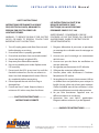
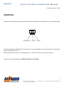
Chalice Series
I N S TA L L AT I O N & O P E R AT I O N M a n u a l
Chalice
Installation &
Operation Manual
Lighting
BRINGING IMAGINATION TO LIGHT
57 Alexander St., Yonkers, NY 10701
© 2012 Altman Stage Lighting, Inc.
Tel: 914-476-7987
1
Visit our website at www.altmanlighting.com
Chalice Series
I N S TA L L AT I O N & O P E R AT I O N M a n u a l
Table of Contents
Safety Instructions
Page 3
Description and Packing List
Page 4
Setup and Installation
Page 5
Features
Page 6
Operation
Page 7
DMX Mode
Page 8
∙ Personalities
Page 9
∙ Resolution
Page 10
∙ Stand Alone Mode
Page 11
∙ Fixed Color Mode
Page 12
∙ Master Mode
Page 13
Wiring Details
Page 14
J-Box and Ball Mount Details
Page 15
Cable Mount Details
Page 16
Pendant Chalice, 100W
Page 17
Pendant Chalice, 50W
Page 18
Recessed Chalice, 100W
Page 19
Recessed Chalice, 50W
Page 20
Lighting
BRINGING IMAGINATION TO LIGHT
57 Alexander St., Yonkers, NY 10701
© 2012 Altman Stage Lighting, Inc.
Tel: 914-476-7987
2
Visit our website at www.altmanlighting.com
Chalice Series
I N S TA L L AT I O N & O P E R AT I O N M a n u a l
SAFETY INSTRUCTIONS
INSTRUCTIONS PERTAINING TO A RISK OF
FIRE, ELECTRICAL SHOCK, OR INJURY TO
PERSONS FOR SPECTRA SERIES LED
LIGHTING FIXTURES.
LES INSTRUCTIONS AU SUJET D’UN
RISQUE D’INCENDIE LE CHOC
ÉLECTRIQUE, OU LA BLESSURE AUX
PERSONNES POUR SS-CYC-100.
AVERTISSEMENT! - POUR RÉDUIRE LE RISQUE
WARNING! - TO REDUCE THE RISK OF FIRE, ELECTRIC D’INCENDIE, LE CHOC ÉLECTRIQUE, OU LA BLESSURE
SHOCK, OR INJURY TO PERSONS, FOLLOW THESE AUX PERSONNES, SUIVRE CES INSTRUCTIONS DE
IMPORTANT SAFETY INSTRUCTIONS:
SÉCURITÉ IMPORTANTES:
1. Turn off, unplug power, and allow fixture to cool
before cleaning or servicing.
2. Ensure that fixture is properly grounded.
3. Ensure that ventilation slots are not obstructed.
4. Do not look directly at lighted LEDs.
5. Keep away from flammable materials.
6. No user serviceable parts inside. Replace entire
LED assembly.
7. Do not touch the LEDs at any time. Use a soft lint
free cloth to clean lens. Do not use solvents to
clean. Use cloth dampened with water. Allow to
dry completely before reenergizing.
8. Do not operate the unit with a missing or
damaged lens.
9. Fixtures are Non-IC rated. Keep insulation a
minimum of 3-inches away from the fixture.
----------SAVE THESE INSTRUCTIONS!----------INSTRUCTIONS DE SÛRETÉ
1. Éteignez, débranchez la puissance, et permettez
au montage de se refroidir avant le nettoyage ou
l’entretien.
2. Assurez-vous que le montage est correctement
relié à la terre.
3. Assurez-vous que des fentes de ventillation ne
sont pas obstruées.
4. Ne regardez pas directement la LED allumée.
5. S’éloigner des materiaux inflammables.
6. Aucunes pièces utiles d’utilisateur à l’intérieur.
Remplacez la LED entière.
7. Ne touchez pas les voyants à tout moment. Utilisez
un chiffon doux non pelucheux pour nettoyer la
lentille. Ne pas utiliser de solvants pour nettoyer.
Chiffon humidifié avec de l’eau utilisation. Laisser
sécher complètement avant de redynamisation.
8. Ne pas faire fonctionner l’appareil avec un
diffuseur antérieur ou une lampe.
9. Accessoires fixes sont Non-IC appréciation.
Éloigner isolation minimum 3-po de l’appareil.
----------GARDER CES INSTRUCTIONS!----------
Lighting
BRINGING IMAGINATION TO LIGHT
57 Alexander St., Yonkers, NY 10701
© 2012 Altman Stage Lighting, Inc.
Tel: 914-476-7987
3
Visit our website at www.altmanlighting.com
Chalice Series
I N S TA L L AT I O N & O P E R AT I O N M a n u a l
CDR50 & CDR100 Recessed
Chalice™ LED Series Solid
State Lighting Fixture
DESCRIPTION
The CDR50 & CDR100 Recessed Chalice LED lighting fixture is a recessed unit provided with knock-outs and
terminal blocks to provide power and/or data to the fixture in recessed ceiling mount applications only. The
overall construction of the fixture includes corrosion protected steel housing and allows for mounting to
ceiling beams with two adjustable brackets. The fixture is supplied with a state of the art microprocessorcontrolled solid-state LED light engine incorporating 3-watt Luxeon Rebel Red, Green, Blue, and PC-Amber
color or White color LEDs, and on-board power supplies. The LED substrate is coupled to a highly efficient
heat sink and cooling system for prolonged life of the LEDs. All components and electrical devices are UL/
ETL Listed or Recognized. The fixture is Non-IC rated, so keep insulation at least 3-inches away from the
fixture body.
PACKING LIST
The CDR50 & CDR100 Recessed Chalice LED lighting fixture is shipped with the following:
• CDR50 or CDR100 fixture,
• Trim Ring with Spread Lens,
• Adjustable Mounting Hangers,
• This Installation and Instruction Manual.
WARNING:
ALL ELECTRICAL WIRING AND CONNECTIONS SHOULD BE PERFORMED BY A QUALIFIED ELECTRICIAN
Lighting
BRINGING IMAGINATION TO LIGHT
57 Alexander St., Yonkers, NY 10701
© 2012 Altman Stage Lighting, Inc.
Tel: 914-476-7987
4
Visit our website at www.altmanlighting.com
Chalice Series
I N S TA L L AT I O N & O P E R AT I O N M a n u a l
SETUP AND INSTALLATION
Unpacking
Remove the CDR50 & CDR100 Recessed Chalice lighting fixture from its shipping box. Set the unit down on
a flat surface before proceeding. Remove the trim ring and lens from the fixture by squeezing the two tension springs on the trim ring and set aside.
Lamping and Re-lamping
The CDR50 & CDR100 Recessed Chalice lighting fixture is provided with an integral 50W and 100W LED light
engine respectively. Under normal operating conditions, the LED light engine should have a rated life expectancy of over 50,000 hours. There are no user serviceable parts inside. The entire LED assembly will need
to be changed.
Mounting the fixture
The CDR50 & CDR100 are designed for ceiling mount only and away from insulation. Install two mounting
brackets onto either side of the fixture, but removing the ¼-20 screw and mounting the two brackets to the
hole in the fixture side. Cut out an appropriate size 6” diameter hole for the CDR50 or an 8” diameter hole
for the CDR100. Install the fixture from the top of the ceiling onto the hole cutout making sure to align the
center of the LED light engine to the center of the hole. Hold the main fixture body in place and secure each
end of the two mounting brackets to adjacent beams. Secure the four ends of the brackets in place to a
beam using either drywall or wood screws. Note: Use the beams to support the fixture, not the surface of the
ceiling.
Connecting power and/or data to the fixture
Wiring should be done by a qualified electrician. AC high power and DC low voltage DMX512 data can be
brought to the fixture through any of the many knock-outs provided. Make sure the fixture is wired to a
properly grounded circuit breaker. For DMX512, connect COM, Data+ and Data- as marked inside the fixture.
Focusing the fixture
Install the trim ring with the lens back onto the fixture by squeezing the two torsion springs into the two
slots provided on the fixture from the bottom. To change lenses in the CDR50, pull the two tabs holding the
lens down up and away with a needle nose pliers. Put them back in place when the new lens is installed. For
the CDR100, simply slide the lens retaining pins, clips, or tabs out of the way and back in place onto the new
lens.
Cleaning the fixture
Routine cleaning of the CDR50 & CDR100 Recessed Chalice lighting fixture will provide years of prolonged
use. Use compressed air to blow off any dust and dirt from the lens, reflector, electronics and heat sink. For
the lens, use a soft lint-free cloth dampened with water to clean the lens of dust and dirt. Dry off completely
with compressed air or a dry lint-free cloth.
ETL FILE LISTING
The CDR50 & CDR100 Recessed Chalice lighting fixture is ETL and c-ETL listed under Altman File 9700680 for
UL1598 and UL8750 for Luminaires.
Lighting
BRINGING IMAGINATION TO LIGHT
57 Alexander St., Yonkers, NY 10701
© 2012 Altman Stage Lighting, Inc.
Tel: 914-476-7987
5
Visit our website at www.altmanlighting.com
Chalice Series
I N S TA L L AT I O N & O P E R AT I O N M a n u a l
Features
The Chalice SERIES LED lighting fixtures are the first of its kind in the Theatrical and Architectural Lighting
Industry offered by Altman Lighting.
•
Available in 3,000K White, 3,000K-6,000K tunable white, RGBA, RGBW or custom color
combinations.
•
Compatible with DMX512 and RDM protocols.
•
8/16 bit DMX512 control for smoother dimming.
•
Patented optical system utilizing Homogenized Pixelation™ lens - provides smooth, even
illumination and reduces pixelization from projected view.
•
On board power supply, microprocessor controller, and current drivers.
•
Feed thru DMX/RDM data with a maximum total run of 1000 feet.
•
High-frequency PWM for quiet operation with no audible noise.
•
Wiring of AC power and DMX data through screw terminal blocks
•
Push button addressing.
•
Stand-Alone Pre-programmed modes.
•
Keypad Lock functions to prevent accidental Re-Programming.
•
Efficient cooling system offering Silent Operation with No Fans.
•
Convenient access to LED light engine and electronics for maintenance and repair.
WARNING: ALL ELECTRICAL WIRING AND CONNECTIONS SHOULD BE PERFORMED BY A QUALIFIED
ELECTRICIAN
Lighting
BRINGING IMAGINATION TO LIGHT
57 Alexander St., Yonkers, NY 10701
© 2012 Altman Stage Lighting, Inc.
Tel: 914-476-7987
6
Visit our website at www.altmanlighting.com
Chalice Series
I N S TA L L AT I O N & O P E R AT I O N M a n u a l
( Firmware Version: V2.3.6)
OPERATION
There are 3 buttons below the 3 digit LED display on the side of the unit. The buttons are : (From left to right)
[ HUNDREDS ] , [ TENS ] , [ ONES ].
All settings for Modes, DMX address, Personalities, etc., can be made by using the three buttons on the back
of the unit while power is on.
(Note: Display goes out after no activity for approx 4 sec. Touch any button once to bring it back on.)
There are 3 main operating Modes: DMX, Fixed Color, and Locked.
Lighting
BRINGING IMAGINATION TO LIGHT
57 Alexander St., Yonkers, NY 10701
© 2012 Altman Stage Lighting, Inc.
Tel: 914-476-7987
7
Visit our website at www.altmanlighting.com
Chalice Series
I N S TA L L AT I O N & O P E R AT I O N M a n u a l
DMX Mode:
DMX Mode is used for Setting DMX address, Personalities, and Stand-alone Effects. This is the default mode
for a new unit. (Also see Fixed Color Mode section on page 9.)
To Switch to DMX Mode from Fixed Color Mode (or vice versa ) :
Wait a few seconds until the display goes blank,
• press and hold the [ ONES ] button
• press and hold the [ TENS ] button
• release the [ ONES ] button
• release the [ TENS ] button.
DMX ADDRESS
To set, press the buttons repeatedly (or hold) to count up until the desired DMX address (1-512), appears on
the display. Wait a few seconds, the display will blink once quickly, and the address is set live and retained in
memory, even if you remove power.
(RDM addressing sent from a remote unit will overwrite local DMX setting.)
PERSONALITIES:
There are 8 different personalities.
Each personality is made up of 3 settings: RESOLUTION (8 Bit /16 Bit), MASTER (On /Off ), and SMOOTHING
(On/Off ) which are explained in greater detail below.
The current active Personality # is displayed for about 1 second during power up. The format is Pxx where xx
is replaced by the active personality #01-08.
To set the desired Personality, you must be in DMX mode (not Fixed Color mode).
To select the personality:
• Press the buttons until the desired personality address 601-608) appears in the display (see list below).
• Wait a few seconds, and a confirmation display will appear that shows a question mark? on the left,
followed by the personality #. This gives you an opportunity to either accept or reject the new setting.
• To accept the new personality, press the [ ONES ] button.
• To reject the new personality, press the [HUNDREDS] button (below the ? ).
Once the new personality is accepted, it is entered into memory and retained even if power is disconnected.
Once personality is either accepted or rejected, the display will go back to the current DMX address. The
default personality for a new unit is #02.
EXAMPLE: Let's say that we want to select personality #05. We enter 605 on the display.
After a few seconds the display will show ?05 . Since we want this, we press the [ONES] button
(below the 5 ), and that enters personality #05 into memory.
Lighting
BRINGING IMAGINATION TO LIGHT
57 Alexander St., Yonkers, NY 10701
© 2012 Altman Stage Lighting, Inc.
Tel: 914-476-7987
8
Visit our website at www.altmanlighting.com
Chalice Series
I N S TA L L AT I O N & O P E R AT I O N M a n u a l
PERSONALITY ADDRESS SETTINGS LIST
601-608: 4-COLOR CHANNELS:
601
602
603
604
605
606
607
608
Personality #01
8 bit
Uses 4 DMX Channels
Channel order is RGBA
Personality #02
8 bit
Uses 4 DMX Channels
Channel order is RGBA
Personality #03
8 bit
Uses 5 DMX Channels
Channel order is RGBAM
Personality #04
8 bit
Uses 5 DMX Channels
Channels order is RGBAM
Personality #05
16 bit
Uses 8 DMX Channels
Channel order is RrGgBbAa
Personality #06
16 bit
Uses 8 DMX Channels
Channel order is RrGgBbAa
Personality #07
16 bit
Uses 10 DMX Channels
Channel order is RrGgBbAaMm
Personality #08
16 bit
Uses 10 DMX Channels
Channel order is RrGgBbAaMm
Master OFF
Smoothing OFF
Master OFF
Smoothing ON
Master ON
Smoothing OFF
Master ON
Smoothing ON
Master OFF
Smoothing OFF
Master OFF
Smoothing ON
Master ON
Smoothing OFF
Master ON
Smoothing ON
609-612: 1-COLOR CHANNELS
609
Personality #09
8 bit
Smoothing OFF
8 bit
Smoothing ON
16 bit
Smoothing OFF
16 bit
Smoothing ON
Uses 1 DMX Channel
610
Personality #10
Uses 1 DMX Channel
611
Personality #11
Uses 2 DMX Channels
612
Personality #12
Uses 2 DMX Channels
Lighting
BRINGING IMAGINATION TO LIGHT
57 Alexander St., Yonkers, NY 10701
© 2012 Altman Stage Lighting, Inc.
Tel: 914-476-7987
9
Visit our website at www.altmanlighting.com
Chalice Series
I N S TA L L AT I O N & O P E R AT I O N M a n u a l
RESOLUTION is selectable as either:
8 Bit (one DMX channel per color) this is normal resolution,
or
16 Bit (two DMX channels per color) Coarse+Fine high resolution similar to moving lights.
If unit is in 8 Bit mode, and the unit is set to DMX Channel 001, then the DMX channels would be:
CH1
CH2
CH3
CH4
Red
Green
Blue
Amber*
If unit is in 16 Bit Mode, and the unit was set to DMX Channel 001, then the DMX channels would be:
CH1
CH3
CH5
CH7
Red Coarse
Green Coarse
Blue Coarse
Amber* Coarse
CH2
CH4
CH6
CH8
Red Fine
Green Fine
Blue Fine
Amber* Fine
Master Channel is selectable as ON or OFF and provides a Master fade channel that dims
all 4 colors proportionally at the same time in order to maintain the color .
If you are in 8 Bit mode and the unit is set to DMX Channel 001, then the DMX channels would be:
CH1
CH2
CH3
CH4
CH5
Red
Green
Blue
Amber*
Master
If you are in 16 Bit mode and the unit is set to DMX Channel 001, then the DMX channels would be:
CH1
CH3
CH5
CH7
CH9
Red Coarse
Green Coarse
Blue Coarse
Amber* Coarse
Master Coarse
CH2
CH4
CH6
CH8
Ch10
Red Fine
Green Fine
Blue Fine
Amber* Fine
Master Fine
SMOOTHING is selectable as ON or OFF and provides a smooth transition ramp from one level to
another in a similar way to how an incandescent lamp behaves. This helps to eliminate the "steppiness"
associated with LED fixtures that is caused by the instantaneous response of LEDs.
*Amber if RGBA, or White if RGBW
Lighting
BRINGING IMAGINATION TO LIGHT
57 Alexander St., Yonkers, NY 10701
© 2012 Altman Stage Lighting, Inc.
Tel: 914-476-7987
10
Visit our website at www.altmanlighting.com
Chalice Series
I N S TA L L AT I O N & O P E R AT I O N M a n u a l
STAND-ALONE MODE (does not require a control console):
Note: Must be in DMX Mode (see page 6). If Master Mode (see page 10) is on, stand-alone effects from a
single unit will control other units connected via DMX cable to all synchronize. Set other units to DMX
channel 001.
(Do not use the Stand-Alone Effects while connected to a control console or a conflict may result.)
Color Fades (700-799):
700 - 709
R»A»G»B fade
700 = faster - 709 = slower
740 - 749
B»G»A»R fade
740 = faster - 749 = slower
780 - 789
R»A»G»B»W fade
780 = faster - 789 = slower
790 - 799
W»B»G»A»R fade
790 = faster - 799 = slower
Strobes (800-879):
800 - 809
WHITE STROBE
800 = faster - 809 = slower
810 - 819
RED STROBE
810 = faster - 819 = slower
820 - 829
AMBER STROBE
820 = faster - 829 = slower
830 - 839
GREEN STROBE
830 = faster - 839 = slower
840 - 849
BLUE STROBE
840 = faster - 849 = slower
850 - 858
R-A-G-B RAINBOW STROBE
850 = faster - 859 = slower
870 - 879
B-G-A-R RAINBOW STROBE
870 = faster - 879 = slower
Lighting
BRINGING IMAGINATION TO LIGHT
57 Alexander St., Yonkers, NY 10701
© 2012 Altman Stage Lighting, Inc.
Tel: 914-476-7987
11
Visit our website at www.altmanlighting.com
Chalice Series
I N S TA L L AT I O N & O P E R AT I O N M a n u a l
FIXED COLOR MODE:
This is a special mode that allows you to manually select colors for a single unit using the 3 keys. (Also see
DMX Mode on page 6.)
To enter Fixed Color Mode (or exit to DMX Mode) :
Wait a few seconds until the display goes blank,
1. press and hold the [ ONES ] button
2. press and hold the [ TENS ] button
3. release the [ ONES ] button
4. release the [ TENS ] button
While in Fixed Color Mode, the hundreds button cycles through 'r', 'G', 'b', and 'A' colors . The tens and ones
digits select 0-99 values. Level 99 is that channel at full.
Locked Mode:
To Lock (or unlock) the buttons:
Wait a few seconds until the display goes blank,
1. press and hold the [ ONES ] button
2. press and hold the [ HUNDREDS ] button
3. release the [ ONES ] button
4. release the [ HUNDREDS ] button.
Display will show
Loc for a moment and then blink. Buttons will ave no effect until they are unlocked.
Lighting
BRINGING IMAGINATION TO LIGHT
57 Alexander St., Yonkers, NY 10701
© 2012 Altman Stage Lighting, Inc.
Tel: 914-476-7987
12
Visit our website at www.altmanlighting.com
Chalice Series
I N S TA L L AT I O N & O P E R AT I O N M a n u a l
MASTER MODE ( Different than the Master Channel described on page 7.)
Master Mode only works while in STAND-ALONE EFFECTS MODE (see page 8). It causes the unit that is
set to Master Mode to behave like a console and Transmit 4-channel (RGBA) 8-bit DMX set on address 001,
reflecting its present light output.
Note: Only the first unit that is going to serve as the MASTER fixture should be set to Stand-alone Effects
mode with Master Mode on. Stand-alone Effects Mode with Master Mode on should also not be used while
units are connected to a DMX console. All fixtures following the Master fixture should be set with the Master
Mode OFF, for Normal Operation.
To Turn on MASTER MODE:
1.
2.
3.
4.
5.
6.
7.
8.
Place fixture in Stand-alone Mode (see page 8)
Wait a few seconds until the display goes blank
Press and hold the [ HUNDREDS ] button
Press and hold the [ ONES ] button
Release the [ HUNDREDS ] button
Release the [ ONES ] button
Display will show ON for a moment to indicate new setting and then blink.
Address remaining fixtures connected to the MASTER fixture to DMX address 001
To Turn off the MASTER MODE:
Wait a few seconds until the display goes blank
Press and hold the [ HUNDREDS ] button
Press and hold the [ ONES ] button
Release the [ HUNDREDS ] button
Release the [ ONES ] button
Display will show OFF for a moment to indicate new setting and then blink.
Lighting
BRINGING IMAGINATION TO LIGHT
57 Alexander St., Yonkers, NY 10701
© 2012 Altman Stage Lighting, Inc.
Tel: 914-476-7987
13
Visit our website at www.altmanlighting.com
Chalice Series
I N S TA L L AT I O N & O P E R AT I O N M a n u a l
Single DMX Cable:
Cat-5 Cable pinout for RJ45 connector:
DATA 1 is used for DMX IN (+,-,Common)
DATA 2 IS USED FOR DMX OUT (+,-,Common)
White/Orange
Orange
> DATA 1+
> DATA 1-
>RJ45 Pin 1 (part of DMX IN)
>RJ45 Pin 2 (part of DMX IN)
White/Green
Green
> DATA 2+
> DATA 2-
>RJ45 Pin 3 (part of DMX OUT)
>RJ45 Pin 6 (part of DMX OUT)
Blue
White/Blue
> N/C
> N/C
>RJ45 Pin 4
>RJ45 Pin 5
White/Brown
Brown
> DATA 1 COMMON
> DATA 2 COMMON
Lighting
BRINGING IMAGINATION TO LIGHT
>RJ45 Pin 7 (part of DMX IN)
>RJ45 Pin 8 (part of DMX OUT)
57 Alexander St., Yonkers, NY 10701
© 2012 Altman Stage Lighting, Inc.
Tel: 914-476-7987
13S
Visit our website at www.altmanlighting.com
Chalice Series
I N S TA L L AT I O N & O P E R AT I O N M a n u a l
WIRING DETAILS:
Pendant:
Data
Connection
Voltage
Barrier
Cat 5 DMX Data Connection
White/Orange: Data 1+, XLR Pin 3
Orange: Data 1-, XLR Pin 2
White/Green: Data 2+, XLR Pin 5(OPTIONAL)
Green: Data 2-, XLR Pin 4(OPTIONAL)
White/Blue: Not Used
Blue: Not Used
White/Brown: Common, XLR Pin 1
Brown: Common, XLR Pin 1
Power
Connection
Cat 5 DMX Data Connection
White/Orange: Data 1+, XLR Pin 3
Orange: Data 1-, XLR Pin 2
White/Green: Data 2+, XLR Pin 5(OPTIONAL)
Green: Data 2-, XLR Pin 4(OPTIONAL)
White/Blue: Not Used
Blue: Not Used
White/Brown: Data 1 Common, XLR Pin 1
Brown: Data 2 Common, XLR Pin 1
Data
Connection
Power Connection
Black: Line
White: Common
Green: Ground
Recessed:
Cat 5 DMX Data Connection
White/Orange: Data 1+, XLR Pin 3
Orange: Data 1-, XLR Pin 2
White/Green: Data 2+, XLR Pin 5(OPTIONAL)
Green: Data 2-, XLR Pin 4(OPTIONAL)
White/Blue: Not Used
Blue: Not Used
White/Brown: Common, XLR Pin 1
Brown: Common, XLR Pin 1
Power Connection
Black: Line
White: Common
Green: Ground
Cat 5 DMX Data Connection
White/Orange: Data 1+, XLR Pin 3
Orange: Data 1-, XLR Pin 2
White/Green: Data 2+, XLR Pin 5(OPTIONAL)
Green: Data 2-, XLR Pin 4(OPTIONAL)
White/Blue: Not Used
Blue: Not Used
White/Brown: Data 1 Common, XLR Pin 1
Brown: Data 2 Common, XLR Pin 1
Lighting
BRINGING IMAGINATION TO LIGHT
57 Alexander St., Yonkers, NY 10701
© 2012 Altman Stage Lighting, Inc.
Tel: 914-476-7987
14
Visit our website at www.altmanlighting.com
CHALICE DOWN LIGHT
WASH LIGHTING
Chalice DMX Terminator Wiring
Chalice DMX Terminator
TOP
FRONT
120 Ohm
Resistor
White/
Brown
White/
Orange
Brown
Orange
White/
Brown
Orange
White/
Orange
Brown
Cat5 Cable from last
Chalice in the line.
DMX termination for Chalice should be installed on
the DMX Cat5 cable bare end on the last fixture in the
communication line.
Lighting
BRINGING IMAGINATION TO LIGHT
57 Alexander St., Yonkers, NY 10701
© 2012 Altman Stage Lighting, Inc.
Tel: 914-476-7987
Visit our website at www.altmanlighting.com
Chalice Series
I N S TA L L AT I O N & O P E R AT I O N M a n u a l
J-Box Connection Details:
Ball Mount Details:
Set
Screw
Threaded
Ball
Ground
Screw
Mounting
Screws
2 x 8--32x1.5”
Canopy
Install the 1/4-20 flat head screw into
the center threaded hole of the cross
bar as shown. The Ground (green)
screw is used by the Electrician to
attach a wire to properly ground the
Chalice LED fixture.
Stem
Chalice
Fixture
Use two (2) 8-32 screws to attach
the crossbar to the junction box.
Not included
Slide the canopy cover up onto the
1/4-20 center screw of the crossbar.
Assemble to 99-CC1/4-202P couplar
as shown and use it to hold the
canopy cover in place. The 18/3 SVT
power cable is fed into the junction
box using the offset hole and 99-102
strain relief provided in the canopy
cover.
Lighting
BRINGING IMAGINATION TO LIGHT
57 Specifi
Alexander
St.,are
Yonkers,
NY
10701 without
Tel:notice.
914-476-7987
cations
subject
to change
© 2012
Altman
Stage
Lighting,
Inc.
15
Visit our website at www.altmanlighting.com
Chalice Series
I N S TA L L AT I O N & O P E R AT I O N M a n u a l
Cable Mount Details:
99-158 crossbar.
Attaches to standard
3.5” octagonal J-box
using (2) 8-32 screws
(J-box not supplied)
Grounding
Screw
8-32 screws
(not supplied)
99-94B-10 canopy.
Manufactured for
the weight of the
fixture.
99-CC1/4-202P
2 piece coupler
3 x 99-102
Strain relief
99-AC3/32-240G
2.5mm flexible aircraft
suspension cable provided,
length to be specified at
time of order. Not field
adjustable
Contractor supplied
cable ties as needed
NOTE: DO NOT extend the
cable end past the 99-GR-1/4-IP
threaded end into the fixture
or damage may occur
99-GR-1/4/IP
cable gripper
(1) 18/3 SVT power cable
will run externally and can
be cable tied to the length
of aircraft cable, wiring preinstalled at the factory
(2) Belden 1592A DMX cables
for Data Feed pre-installed and
are provided by Altman
99-PF-3/8 power feed and preinstalled and provided by Altman
99-81-3/8IP-18
stud extension
Lighting
BRINGING IMAGINATION TO LIGHT
57 Alexander St., Yonkers, NY 10701
© 2012 Altman Stage Lighting, Inc.
Tel: 914-476-7987
16
Visit our website at www.altmanlighting.com
Chalice Series
I N S TA L L AT I O N & O P E R AT I O N M a n u a l
Lighting
BRINGING IMAGINATION TO LIGHT
57 Alexander St., Yonkers, NY 10701
© 2012 Altman Stage Lighting, Inc.
Tel: 914-476-7987
17
Visit our website at www.altmanlighting.com
Installation Manual
WALL MOUNT CHALICE
STEP 1: FIX THE YOKE TO THE WALL WITH APPROPRIATE FASTENERS
STEP 2 : REMOVE THE SHOULDER BOLTS FROM THE FIXTURE
STEP 3: INSERT THE FIXTURE BETWEEN THE YOKE AND FASTEN IT WITH REMOVED
FASTENERS (STEP 2). MAKE SURE RUBBER WASHERS ARE IN BETWEEN YOKE AND
FIXTURE.
STEP 4: PERFORM THE REQUIRED WIRING TO LIGHTUP THE UNIT.
Chalice Series
I N S TA L L AT I O N & O P E R AT I O N M a n u a l
Lighting
BRINGING IMAGINATION TO LIGHT
57 Alexander St., Yonkers, NY 10701
© 2012 Altman Stage Lighting, Inc.
Tel: 914-476-7987
Recessed Chalice, 100W
CDR100
18
Visit our website at www.altmanlighting.com
Chalice Series
I N S TA L L AT I O N & O P E R AT I O N M a n u a l
Lighting
BRINGING IMAGINATION TO LIGHT
57 Alexander St., Yonkers, NY 10701
© 2012 Altman Stage Lighting, Inc.
Tel: 914-476-7987
Recessed Chalice, 50W
CDR50
19
Visit our website at www.altmanlighting.com