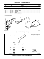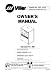
1
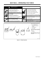
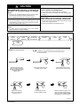
May 1995 Form: OM-1592A OWNER’S MANUAL MC-80 And MC-80M Air-Cooled Plasma Arc Cutting (PAC) Torches Can Be Used For Plasma Arc Gouging (PAG) 80 Amperes, 120 Volts DC At 100% Duty Cycle Safety Interlock Devices Shut Down Power Source Hand-Held Torch Equipped With Either 25 Or 50 ft (7.6 Or 15.2 m) Cable Machine-Held Torch Equipped With 50 ft (15.2 m) Cable Fully Assembled And Supplied With Consumable Kit Read and follow these instructions and all safety blocks carefully. Give this manual to the operator. Have only trained and qualified persons install, operate, or service this unit. For help, call your distributor Call your distributor if you do not understand the directions. or: MILLER Electric Mfg. Co., P.O. Box 1079, Appleton, WI 54912 414-734-9821 cover 5/94 – Ref. ST-800 895 1995 MILLER Electric Mfg. Co. PRINTED IN USA From Miller to You Thank you and congratulations on choosing Miller. Now you can get the job done and get it done right. We know you don’t have time to do it any other way. That’s why when Niels Miller first started building arc welders in 1929, he made sure his products offered long-lasting value and superior quality. Like you, his customers couldn’t afford anything less. Miller products had to be more than the best they could be. They had to be the best you could buy. Today, the people that build and sell Miller products continue the tradition. They’re just as committed to providing equipment and service that meets the high standards of quality and value established in 1929. This Owner’s Manual is designed to help you get the most out of your Miller products. Please take time to read the Safety precautions. They will help you protect yourself against potential hazards on the worksite. We’ve made installation and operation quick and easy. With Miller you can count on years of reliable service with proper maintenance. And if for some reason the unit needs repair, there’s a Troubleshooting section that will help you Miller is the first welding figure out what the problem is. The parts list equipment manufacturer in will then help you to decide which exact part the U.S.A. to be registered to the ISO 9001 Quality System you may need to fix the problem. Warranty and Standard. service information for your particular model are also provided. Miller Electric manufactures a full line of welders and welding related equipment. For information on other quality Miller products, contact your local Miller distributor to receive the latest full line catalog or individual catalog sheets. To locate your nearest distributor or service agency call 1-800-4-A-Miller, or visit us at www.MillerWelds.com on the web. Working as hard as you do – every power source from Miller is backed by the most hassle-free warranty in the business. Miller offers a Technical Manual which provides more detailed service and parts information for your unit. To obtain a Technical Manual, contact your local distributor. Your distributor can also supply you with Welding Process Manuals such as SMAW, GTAW, GMAW, and GMAW-P. PLASMA ARC CUTTING SAFETY PRECAUTIONS WARNING PLASMA ARC CUTTING can be hazardous. PROTECT YOURSELF AND OTHERS FROM POSSIBLE SERIOUS INJURY OR DEATH. KEEP CHILDREN AWAY. PACEMAKER WEARERS KEEP AWAY UNTIL CONSULTING YOUR DOCTOR. In cutting, as in most jobs, exposure to certain hazards occurs. Cutting is safe when precautions are taken. The safety information given below is only a summary of the more complete safety information that will be found in the Safety Standards listed on the next page. Read and follow all Safety Standards. HAVE ALL INSTALLATION, OPERATION, MAINTENANCE, AND REPAIR WORK PERFORMED ONLY BY QUALIFIED PEOPLE. CUTTING can cause fire or explosion. Hot metal and sparks blow out from the cutting arc. The flying sparks and hot metal, hot workpiece, and hot equipment can cause fires and burns. Check and be sure the area is safe before doing any cutting. 7. Do not cut on closed containers such as tanks or drums. 8. Connect work cable to the work as close to the cutting area as practical to prevent cutting current from traveling long, possibly unknown paths and causing electric shock and fire hazards. 9. Never cut containers with potentially flammable materials inside – they must be emptied and properly cleaned first. 1. Protect yourself and others from flying sparks and hot metal. 2. Do not cut where flying sparks can strike flammable material. 3. Remove all flammables within 35 ft (10.7 m) of the cutting arc. If this is not possible, tightly cover them with approved covers. 4. Be alert that sparks and hot materials from cutting can easily go through small cracks and openings to adjacent areas. 5. Watch for fire, and keep a fire extinguisher nearby. 6. Be aware that cutting on a ceiling, floor, bulkhead, or partition can cause fire on the hidden side. 10. Do not cut in atmospheres containing explosive dust or vapors. ELECTRIC SHOCK can kill. 8. Check and be sure that input power cord ground wire is properly connected to ground terminal in disconnect box or that cord plug is connected to a properly grounded receptacle outlet – always verify the supply ground. 9. When making input connections, attach proper grounding conductor first. 10. Frequently inspect input power cord for damage or bare wiring – replace cord immediately if damaged – bare wiring can kill. 11. Turn off all equipment when not in use. 12. Inspect and replace any worn or damaged torch cable leads. 13. Do not wrap torch cable around your body. 14. Ground the workpiece to a good electrical (earth) ground if required by codes. 15. Use only well-maintained equipment. Repair or replace damaged parts at once. 16. Wear a safety harness if working above floor level. 17. Keep all panels and covers securely in place. 18. Do not bypass or try to defeat the safety interlock systems. 19. Use only torch(es) specified in Owner’s Manual. 20. Keep away from torch tip and pilot arc when trigger is pressed. 21. Clamp work cable with good metal-to-metal contact to workpiece (not piece that will fall away) or worktable as near the cut as practical. Touching live electrical parts can cause fatal shocks or severe burns. The torch and work circuit is electrically live whenever the output is on. The input power circuit and machine internal circuits are also live when power is on. Plasma arc cutting requires higher voltages than welding to start and maintain the arc (200 to 400 volts dc are common), but also uses torches designed with safety interlock systems which turn off the machine when the shield cup is loosened or if tip touches electrode inside the nozzle. Incorrectly installed or improperly grounded equipment is a hazard. 1. Do not touch live electrical parts. 2. Wear dry, hole-free insulating gloves and body protection. 3. Insulate yourself from work and ground using dry insulating mats or covers big enough to prevent any physical contact with the work or ground. 4. Do not touch torch parts if in contact with the work or ground. 5. Turn off power before checking, cleaning, or changing torch parts. 6. Disconnect input power before installing or servicing this equipment. Lockout/tagout input power according to OSHA CFR 1910.147 (see Safety Standards). 7. Properly install and ground this equipment according to its Owner’s Manual and national, state, and local codes. 11. Do not cut pressurized cylinders, pipes, or vessels. 12. Do not cut containers that have held combustibles. 13. Wear oil-free protective garments such as leather gloves, heavy shirt, cuffless trousers, high shoes, and a cap. 14. Do not locate unit on or over combustible surfaces. 15. Remove any combustibles, such as a butane lighter or matches, from your person before doing any cutting. ARC RAYS can burn eyes and skin. NOISE can damage hearing. Arc rays from the cutting process produce intense visible and invisible (ultraviolet and infrared) rays that can burn eyes and skin. Prolonged noise from some cutting applications can damage hearing if levels exceed limits specified by OSHA (see Safety Standards). 1. Wear face protection (helmet or shield) with correct shade of filter to protect your face and eyes when cutting or watching. ANSI Z49.1 (see Safety Standards) suggests a No. 9 shade (with No. 8 as minimum) for all cutting currents less than 300 amperes. Z49.1 adds that lighter filter shades may be used when the arc is hidden by the workpiece. As this is normally the case with low current cutting, the shades suggested in Table 1 are provided for the operator’s convenience. 2. Wear approved safety glasses with side shields. 3. Use protective screens or barriers to protect others from flash and glare; warn others not to watch the arc. 4. Wear protective clothing made from durable, flame-resistant material (wool and leather) and foot protection. 1. Use approved ear plugs or ear muffs if noise level is high. 2. Warn others nearby about noise hazard. Table 1. Eye Protection For Plasma Arc Cutting Current Level In Amperes Below 20 20 – 40 40 – 60 60 – 80 Minimum Shade Number #4 #5 #6 #8 sr2 11/92 FUMES AND GASES can be hazardous to your health. Cutting produces fumes and gases. Breathing these fumes and gases can be hazardous to your health. 1. Keep your head out of the fumes. Do not breathe the fumes. 2. If inside, ventilate the area and/or use exhaust at the arc to remove cutting fumes and gases. 3. If ventilation is poor, use an approved air-supplied respirator. 4. Read the Material Safety Data Sheets (MSDSs) and the manufacturer’s instruction for metals to be cut, coatings, and cleaners. PLASMA ARC can cause injury. The heat from the plasma arc can cause serious burns. The force of the arc adds greatly to the burn hazard. The intensely hot and powerful arc can quickly cut through gloves and tissue. 1. Keep away from the torch tip. 2. Do not grip material near the cutting path. FLYING SPARKS AND HOT METAL can cause injury. Chipping and grinding cause flying metal. As welds cool, they can throw off slag. CYLINDERS can explode if damaged. Gas cylinders contain gas under high pressure. If damaged, a cylinder can explode. Since gas cylinders are normally part of metalworking processes, be sure to treat them carefully. 1. Protect compressed gas cylinders from excessive heat, mechanical shocks, slag, open flame, sparks, and arcs. 2. Install and secure cylinders in an upright position by chaining them to a stationary support or equipment cylinder rack to prevent falling or tipping. 5. Work in a confined space only if it is well ventilated, or while wearing an air-supplied respirator. Fumes from cutting and oxygen depletion can alter air quality causing injury or death. Be sure the breathing air is safe. 6. Do not cut in locations near degreasing, cleaning, or spraying operations. The heat and rays of the arc can react with vapors to form highly toxic and irritating gases. 7. Do not cut on coated metals, such as galvanized, lead, or cadmium plated steel, unless the coating is removed from the cutting area, the area is well ventilated, and if necessary, while wearing an air-supplied respirator. The coatings and any metals containing these elements can give off toxic fumes when cut. 8. Do not cut containers with toxic or reactive materials inside or containers that have held toxic or reactive materials – they must be emptied and properly cleaned first. 3. The pilot arc can cause burns – keep away from torch tip when trigger is pressed. 4. Wear proper flame-retardant clothing covering all exposed body areas. 5. Point torch away from your body and toward work when pressing the torch trigger – pilot arc comes on immediately. 6. Turn off power source and disconnect input power before disassembling torch or changing torch parts. 7. Use only torch(es) specified in the Owner’s Manual. 1. Wear approved face shield or safety goggles with side shields. 2. Wear proper body protection to protect skin. 3. Wear flame-resistant ear plugs or ear muffs to prevent sparks from entering ears. 3. Keep cylinders away from any cutting or other electrical circuits. 4. Never allow electrical contact between a plasma arc torch and a cylinder. 5. Never cut on a pressurized cylinder – explosion will result. 6. Use only correct gas cylinders, regulators, hoses, and fittings designed for the specific application; maintain them and associated parts in good condition. 7. Turn face away from valve outlet when opening cylinder valve. 8. Keep protective cap in place over valve except when cylinder is in use or connected for use. 9. Read and follow instructions on compressed gas cylinders, associated equipment, and CGA publication P-1 listed in Safety Standards. PRINCIPAL SAFETY STANDARDS Safety in Welding and Cutting, ANSI Standard Z49.1, from American Welding Society, 550 N.W. LeJeune Rd, Miami FL 33126 Safety and Health Standards, OSHA 29 CFR 1910, from Superintendent of Documents, U.S. Government Printing Office, Washington, D.C. 20402. Recommended Practices for Plasma Arc Cutting, American Welding Society Standard AWS C5.2, from American Welding Society, 550 N.W. LeJeune Rd, Miami, FL 33126 Recommended Safe Practices for the Preparation for Welding and Cutting of Containers That Have Held Hazardous Substances, American Welding Society Standard AWS F4.1, from American Welding Society, 550 N.W. LeJeune Rd, Miami, FL 33126 sr2 11/92 National Electrical Code, NFPA Standard 70, from National Fire Protection Association, Batterymarch Park, Quincy, MA 02269. Safe Handling of Compressed Gases in Cylinders, CGA Pamphlet P-1, from Compressed Gas Association, 1235 Jefferson Davis Highway, Suite 501, Arlington, VA 22202. Code for Safety in Welding and Cutting, CSA Standard W117.2, from Canadian Standards Association, Standards Sales, 178 Rexdale Boulevard, Rexdale, Ontario, Canada M9W 1R3. Safe Practices For Occupation And Educational Eye And Face Protection, ANSI Standard Z87.1, from American National Standards Institute, 1430 Broadway, New York, NY 10018. Cutting And Welding Processes, NFPA Standard 51B, from National Fire Protection Association, Batterymarch Park, Quincy, MA 02269. EMF INFORMATION NOTE Considerations About Welding And The Effects Of Low Frequency Electric And Magnetic Fields The following is a quotation from the General Conclusions Section of the U.S. Congress, Office of Technology Assessment, Biological Effects of Power Frequency Electric & Magnetic Fields – Background Paper, OTA-BP-E-53 (Washington, DC: U.S. Government Printing Office, May 1989): “. . . there is now a very large volume of scientific findings based on experiments at the cellular level and from studies with animals and people which clearly establish that low frequency magnetic fields can interact with, and produce changes in, biological systems. While most of this work is of very high quality, the results are complex. Current scientific understanding does not yet allow us to interpret the evidence in a single coherent framework. Even more frustrating, it does not yet allow us to draw definite conclusions about questions of possible risk or to offer clear science-based advice on strategies to minimize or avoid potential risks.” To reduce magnetic fields in the workplace, use the following procedures: 1. Keep cables close together by twisting or taping them. 2. Arrange cables to one side and away from the operator. 3. Do not coil or drape cables around the body. 4. Keep welding power source and cables as far away as practical. 5. Connect work clamp to workpiece as close to the weld as possible. About Pacemakers: The above procedures are among those also normally recommended for pacemaker wearers. Consult your doctor for complete information. mod10.1 4/93 TABLE OF CONTENTS SECTION 1 – SAFETY INFORMATION . . . . . . . . . . . . . . . . . . . . . . . . . . . . . . . . . . . . . . . . . . . . . . . . . . . . 1 SECTION 2 – SPECIFICATIONS . . . . . . . . . . . . . . . . . . . . . . . . . . . . . . . . . . . . . . . . . . . . . . . . . . . . . . . . . . 2-1. Duty Cycle . . . . . . . . . . . . . . . . . . . . . . . . . . . . . . . . . . . . . . . . . . . . . . . . . . . . . . . . . . . . . . . . . . . . 1 2 SECTION 3 – INSTALLATION . . . . . . . . . . . . . . . . . . . . . . . . . . . . . . . . . . . . . . . . . . . . . . . . . . . . . . . . . . . . 3 3-1. 3-2. Installing Hand-Held Torch . . . . . . . . . . . . . . . . . . . . . . . . . . . . . . . . . . . . . . . . . . . . . . . . . . . . . . Installing Machine-Held Torch And Remote Trigger Pendant . . . . . . . . . . . . . . . . . . . . . . . . . 3 4 SECTION 4 – OPERATING THE TORCH . . . . . . . . . . . . . . . . . . . . . . . . . . . . . . . . . . . . . . . . . . . . . . . . . . . 5 SECTION 5 – MAINTENANCE & TROUBLESHOOTING . . . . . . . . . . . . . . . . . . . . . . . . . . . . . . . . . . . . . 8 5-1. 5-2. 5-3. Routine Maintenance . . . . . . . . . . . . . . . . . . . . . . . . . . . . . . . . . . . . . . . . . . . . . . . . . . . . . . . . . . . Checking/Replacing Cup, Tip, And Electrode . . . . . . . . . . . . . . . . . . . . . . . . . . . . . . . . . . . . . . Troubleshooting . . . . . . . . . . . . . . . . . . . . . . . . . . . . . . . . . . . . . . . . . . . . . . . . . . . . . . . . . . . . . . . 8 9 10 SECTION 6 – PARTS LIST . . . . . . . . . . . . . . . . . . . . . . . . . . . . . . . . . . . . . . . . . . . . . . . . . . . . . . . . . . . . . . . 11 Figure 6-1. Torch, MC-80 (Hand-Held) . . . . . . . . . . . . . . . . . . . . . . . . . . . . . . . . . . . . . . . . . . . . . . . . . . Figure 6-2. Consumables And Parts Supplied With Hand-Held Torch . . . . . . . . . . . . . . . . . . . . . . . . Figure 6-3. Torch, MC-80 (Machine-Held) . . . . . . . . . . . . . . . . . . . . . . . . . . . . . . . . . . . . . . . . . . . . . . . . 11 11 12 OM-1592A – 5/95 SECTION 1 – SAFETY INFORMATION mod1.1 2/93 Read all safety messages throughout this manual. Obey all safety messages to avoid injury. Learn the meaning of WARNING and CAUTION. 1 2 2 WARNING ELECTRIC SHOCK can kill. • Do not touch live electrical parts. • Disconnect input power before MOVING PARTS can injure. • Keep away from moving parts. • Keep all panels and covers closed 4 installing or servicing. Safety Alert Symbol 2 Signal Word WARNING means possible death or serious injury can happen. CAUTION 3 1 when operating. CAUTION means possible minor injury or equipment damage can happen. 3 Statement Of Hazard And Result 4 Safety Instructions To Avoid Hazard 5 Hazard Symbol (If Available) 6 Safety Banner 5 READ SAFETY BLOCKS at start of Section 3-1 before proceeding. WARNING 6 Read safety blocks for each symbol shown. 7 7 NOTE Turn Off switch when using high frequency. NOTE Special instructions for best operation – not related to safety. Figure 1-1. Safety Information SECTION 2 – SPECIFICATIONS Table 2-1. Cutting Torch Specification Description Cooling Method Air Overall Dimensions See Figure 2-1 Cable Length For Hand-Held Torch 25 Or 50 ft (7.6 Or 15.2 m) Cable Length For Machine Torch 50 ft (15.2 m) Plasma Gas Air Or Nitrogen Plasma Gas Flow/Pressure 25 ft Cable: 4 CFM (115 L/min) At 70 PSI (483 kPa) 50 ft Cable: 4 CFM (115 L/min) At 90 PSI (621 kPa) Ampere Rating 80 Amperes, 120 Volts DC At 100% Duty Cycle (See Section 2-1) Cutting Capacity 7/8 in (22 mm) Mild Steel, Stainless, And Aluminum Weight 25 ft Cable: Net: 8 lb (3.6 kg); Ship: 9 lb (4.1 kg) 50 ft Cable: Net: 14-1/4 lb (6.5 kg); Ship: 15-1/4 lb (7 kg) OM-1592 Page 1 Hand-Held Torch Inches Millimeters A 10-1/2 267 B 1-3/8 35 C 1-1/4 32 D 1-5/16 33 E 13-11/16 348 A B Machine-Held Torch D C E Ref. ST-800 895 / Ref. ST-801 208 Figure 2-1. Overall Dimensions 2-1. Duty Cycle CAUTION CUTTING LONGER THAN RATED DUTY CYCLE can damage cutter and torch and void warranty. • Do not cut at rated load longer than duty cycle of cutter (see cutter’s Owner’s Manual). Definition 0 10 miscwarn3.1 9/93 100% Duty Cycle At 80 Amperes Duty Cycle is percentage of 10 minutes that cutter and torch can cut at rated load without overheating. Minutes Continuous Cutting sb1.1* 8/93 Figure 2-2. Duty Cycle OM-1592 Page 2 SECTION 3 – INSTALLATION 3-1. Installing Hand-Held Torch WARNING ELECTRIC SHOCK can kill. • • HOT PARTS can cause severe burns. • Do not touch live electrical parts. Allow cooling period before maintaining or servicing. Turn Off cutter, and disconnect input power before installing torch. MOVING PARTS can cause injury. • Keep away from moving parts. swarn8.1* 10/91 Turn Off cutter and remove input power. Remove top of cutter case. Significant DC voltage can remain on capacitors in cutter after unit is Off. Always discharge capacitors according to cutter’s Owner’s Manual before installing torch. 1 1 Trigger Switch Connector 2 Gas Hose Connector 3 Pilot Lead Terminal 4 Boot Insert hose and leads through boot. 2 3 5 Gas Hose 6 Pilot Terminal Connect hose and leads as shown. Reinstall top of case. Rear Panel 4 2 1 5 6 4 Tools Needed: 3/8, 5/8 in Ref. ST-800 895 / ST-800 896 Figure 3-1. Installing Hand-Held Torch Into Cutter OM-1592 Page 3 3-2. Installing Machine-Held Torch And Remote Trigger Pendant WARNING ELECTRIC SHOCK can kill. • • HOT PARTS can cause severe burns. • Do not touch live electrical parts. Allow cooling period before maintaining or servicing. Turn Off cutter, and disconnect input power before installing torch. MOVING PARTS can cause injury. • Keep away from moving parts. swarn8.1* 10/91 Machine-held torches require a customer-supplied external switch or remote trigger control. Significant DC voltage can remain on capacitors in cutter after unit is Off. Always discharge capacitors according to cutter’s Owner’s Manual before installing torch. Turn Off cutter and remove input power. Remove top of cutter case. 9 4 Remote Trigger Leads 2 Strain Relief 3 Boot Install strain relief in location shown. Insert leads through boot and install in strain relief as shown. Be sure insulation jacket is in strain relief. 6 5 1 4 Torch Connection Receptacle 5 Gas Hose 6 Pilot Lead Insert receptacle, hose, and lead through boot. 1 7 Rear Panel Pilot Terminal Connect pilot lead to terminal, and gas hose to fitting as shown. 3 8 Printed Circuit Board PC3 9 Three-Way Connector Connect three-way connector to matching receptacle on PC3, torch connection receptacle, and remote trigger receptacle. Reinstall top of case. 8 5 9 4 7 3 6 2 1 Tools Needed: 3/8, 5/8 in ST-801 208 / ST-801 202 Figure 3-2. Installing Machine-Held Torch And Remote Trigger Pendant Into Cutter OM-1592 Page 4 SECTION 4 – OPERATING THE TORCH WARNING ELECTRIC SHOCK can kill. • • • • CUTTING can cause fire or explosion. • • • • • • Always wear dry insulating gloves. Insulate yourself from work and ground. Do not touch live electrical parts. Keep all panels and covers securely in place. FUMES AND GASES can be hazardous to your health. • • • Keep your head out of the fumes. Ventilate area, or use breathing device. Read Material Safety Data Sheets (MSDSs) and manufacturer’s instructions for material cut. Provide protection from flying sparks. Watch for fire; keep extinguisher nearby. Do not locate unit over combustible surfaces. Do not cut on closed containers. Allow work and equipment to cool before handling. MOVING PARTS can cause injury. • • ARC RAYS can burn eyes and skin; NOISE can damage hearing. • • Do not cut near flammable material. Wear face protection with correct shade of filter. Wear correct eye, ear, and body protection. Keep away from moving parts. Keep all doors, panels, covers, and guards closed and securely in place. See Safety Precautions at beginning of manual for basic cutting safety information. swarn6.1* 10/91 Wear the following while cutting: 1 5 2 3 4 1 Dry, Insulating Gloves 2 Safety Glasses With Side Shields 3 Welding Helmet 4 Face Shield Wear either helmet or face shield with correct shade of filter (See ANSI Z49.1). OR 5 Ear Muffs Wear approved ear muffs or ear plugs if noise exposure exceeds OSHA limits. sb3.1* 1/94 Figure 4-1. Safety Equipment OM-1592 Page 5 CAUTION T I P AND EL ECT RO DE WEAR BEYO ND RE CO M M E NDE D VAL UE S or OP E RAT I O N WITHOUT TIP OR ELECTRODE can damage torch. • • Inspect cup, tip, and electrode before cutting or whenever cutting speed has been significantly reduced (see Section 5-2). Do not operate torch without a tip or electrode in place. INCORRECT PIERCING can damage torch. • When piercing (starting a cut away from metal edge) use a slight standoff distance and hold torch at about 10° angle to prevent sparks from reflecting back at torch. HITTING TORCH ON A HARD SURFACE to remove spatter can damage torch. • • Do not clean torch by hitting it against a hard surface. Hitting hard surfaces can damage torch parts and stop proper operation. HAVI NG PI L O T ARC TURN ON AND OF F REPEATEDLY, such as during the cutting of chain fence, will shorten tip, electrode, and torch life. • • Put a continuous piece of sheet metal under the fence to prevent pilot arc from cycling on and off. Avoid constant starting and restarting of the arc. INCORRECT STANDOFF DISTANCE can damage torch. • For cutting, always use approximately 1/8 in (3 mm) standoff distance between torch tip and workpiece. Install & Connect Equipment Put On Personal Safety Equipment Check Torch Tip, Electrode, And Shield Cup Check Gas/Air Pressure Set Controls Turn On Cutter Begin Cutting EXAMPLE Of Cutting Operation Install standoff guide, place guide onto metal so that torch tip lines up with edge of metal and standoff distance is approx. 1/8 in. Adjust torch speed so sparks go thru metal and out bottom of cut. If cutting arc is not started within 5 seconds of pilot arc, pilot arc will go out. There is a 20-second reset time before the pilot arc can be restarted. Press trigger. After 2 seconds of preflow, pilot arc starts. Pause briefly at end of cut before releasing trigger. After cutting arc starts, slowly start moving torch across metal. Postflow continues for approx. 20 to 30 seconds after releasing trigger; cutting arc can be instantly restarted during postflow by pressing trigger. ST-800 967-A OM-1592 Page 6 Figure 4-2. Sequence Of Plasma Arc Cutting (PAC) CAUTION HITTING TORCH ON A HARD SURFACE to remove spatter can damage torch. • • Do not clean torch by hitting it against a hard surface. Hitting hard surfaces can damage torch parts and stop proper operation. Install & Connect Equipment Turn On Cutter Install Gouging Tip Put On Personal Safety Equipment T I P AND EL ECT RO DE WEAR BEYO ND RE CO M M E NDE D VAL UE S or OP E RAT I O N WITHOUT TIP OR ELECTRODE can damage torch. • • • • Inspect cup, tip, and electrode before cutting or whenever cutting speed has been significantly reduced. Do not operate torch without a tip or electrode in place. Use correct standoff distance. Do not cut with gouging tip. Check Torch Tip, Electrode, And Shield Cup Check Gas/Air Pressure Set Controls Begin Gouging EXAMPLE Of Gouging Operation Use approx. 1/8 in (3 mm) standoff distance at about a 40° angle. If cutting arc is not started within 5 seconds of pilot arc, pilot arc will go out. There is a 20-second reset time before the pilot arc can be restarted. Press trigger. After 2 seconds of preflow, pilot arc starts. Adjust torch speed, arc length and angle as needed. Direct sparks away from torch. Do not gouge too deeply in one pass; make repeated passes if needed. Establish arc length of 1/2 to 1-1/2 in (13 - 38 mm), and slowly start moving torch across metal. Release trigger. Postflow continues for approx. 20 to 30 seconds. Gouging arc can be instantly restarted during postflow by pressing trigger. ST-800 968 Figure 4-3. Sequence Of Plasma Arc Gouging (PAG) OM-1592 Page 7 SECTION 5 – MAINTENANCE & TROUBLESHOOTING WARNING ELECTRIC SHOCK can kill. • • Do not touch live electrical parts. HOT PARTS can cause severe burns. • Allow cooling period before maintaining or servicing. Turn Off cutter, and disconnect input power before inspecting, maintaining, or servicing. Maintenance to be performed only by qualified persons. swarn8.1* 2/93 5-1. Routine Maintenance Turn Off all power before maintaining. 3 Months Each Use See Section 5-2 Cutter Manual Check Tip Electrode, And Cup –– Check Gas/Air Pressure At Cutter Replace Cracked Parts Check Trigger Disabled System Ref. ST-800 895 Figure 5-1. Maintenance Schedule OM-1592 Page 8 Clean And Tighten Torch Connections 3-1 Every Week Cutter Manual Tape Torn Outer Covering –– Torch Body Gas/Air Hose Torch Cable 5-2. Checking/Replacing Cup, Tip, And Electrode CAUTION OVERTIGHTENING will strip threads. • • • Do not overtighten electrode, tip, and cup during assembly. Do not cross-thread parts causing stripping. Use care during torch assembly and parts replacement. T I P AND EL ECT RO DE WEAR BEYO ND RE CO M M E NDE D VAL UE S or OP E RAT I O N WITHOUT TIP OR ELECTRODE can damage torch. • • • • Inspect cup, tip, and electrode before cutting or whenever cutting speed has been significantly reduced. Do not operate torch without a tip or electrode in place. Be sure to use genuine replacement parts. A good practice is to replace both the tip and electrode at the same time. Turn Off cutter, and disconnect input power. 1 Shield Cup Remove shield cup. Check shield cup for cracks, and replace if needed. Also, replace cup if it does not cover the tip. 2 Tip 3 Opening Remove tip. Check tip, and replace if opening is deformed or 50% oversize. If inside of tip is not clean and bright, clean with steel wool. Be sure to remove any pieces of steel wool afterwards. 4 4 Electrode Check electrode. If center has a pit more than a 1/16 in (2 mm) deep, remove and replace electrode using supplied wrench. Do not overtighten. Do not overtighten electrode. 2 5 Standoff Guide Carefully reassemble parts in reverse order. 4 3 1 Thread Size for Electrode: 5/16 - 24 New 1/16 in (2 mm) Pit 2 5 New Worn Tools Needed: Worn (Supplied 171 875) Ref. ST-800 897 / ST-800 973 Figure 5-2. Checking/Replacing Cup, Tip, And Electrode OM-1592 Page 9 5-3. Troubleshooting WARNING ELECTRIC SHOCK can kill. • • HOT PARTS can cause severe burns. • Do not touch live electrical parts. Allow cooling period before maintaining or servicing. Turn Off cutter, and disconnect input power before inspecting, maintaining, or servicing. Troubleshooting to be performed only by qualified persons. swarn8.1* 2/93 Table 5-1. Cutting Trouble Trouble Remedy Section Cutter Gas/Torch trouble light On; cutter Power light Off; no cutting output. Check for properly installed torch tip. Check for blocked hoses. See also cutter Owner’s Manual. 5-2 Check to make sure torch electrode is not touching tip inside the torch. 5-2 Check for clean and sufficient gas/air supply pressure. See cutter Owner’s Manual. –– Unit pilots, but does not transfer. Shorten standoff distance from 1/8 to 1/16 in (3 to 1.6 mm). Be sure work clamp is securely attached. See power source Owner’s Manual. Sparks come out top of cut, or cut is not clean. Arc goes out while cutting. Arc goes on and off while cutting. Low cutting capability. Short torch consumable life. Torch travel speed too fast; reduce travel speed. –– Figure 4-2 Metal being cut is too thick; increase power source output control setting. See power source Owner’s Manual. –– Check torch tip and electrode, and replace if needed. 5-2 Be sure work clamp is securely attached. See power source Owner’s Manual. –– Make sure torch tip is within 1/8 in (3 mm) standoff distance from metal while cutting. Figure 4-2 Increase travel speed, as needed. –– Be sure work clamp is securely attached. See power source Owner’s Manual. –– Torch travel speed is too slow; increase travel speed. Figure 4-2 Check torch tip and electrode, and replace if necessary. 5-2 Be sure work clamp is securely attached. See power source Owner’s Manual. –– Decrease cutting speed. Figure 4-2 Tighten loose torch tip and electrode if needed. –– Check torch tip and electrode if needed. –– Be sure work clamp is securely attached. See power source Owner’s Manual. –– Maintain standoff distance of 1/16 to 1/8 in (1.6 to 3 mm), or use standoff guide. Figure 4-2 Tighten or replace torch tip and electrode if needed. OM-1592 Page 10 Figure 4-2, Figure 4-3 –– SECTION 6 – PARTS LIST Item No. Part No. Description Quantity Figure 6-1. Torch, MC-80 (Hand-Held) ... ... ... ... ... ... ... 1 2 3 4 5 6 6 .......... .......... .......... .......... .......... .......... .......... 172 385 172 384 172 382 172 380 172 381 172 383 172 386 . . TORCH, body assembly (consisting of) . . . . . . . . . . . . . . . . . . . . . . . . . . . . . . . . . . . . TORCH, head . . . . . . . . . . . . . . . . . . . . . . . . . . . . . . . . . . . . . . . . . . . . . . . . . . . . . . . . TRIGGER, switch . . . . . . . . . . . . . . . . . . . . . . . . . . . . . . . . . . . . . . . . . . . . . . . . . . . . . HANDLE . . . . . . . . . . . . . . . . . . . . . . . . . . . . . . . . . . . . . . . . . . . . . . . . . . . . . . . . . . . . . BOOT . . . . . . . . . . . . . . . . . . . . . . . . . . . . . . . . . . . . . . . . . . . . . . . . . . . . . . . . . . . . . CABLE ASSEMBLY, 25ft . . . . . . . . . . . . . . . . . . . . . . . . . . . . . . . . . . . . . . . . . . . . . . . CABLE ASSEMBLY, 50ft . . . . . . . . . . . . . . . . . . . . . . . . . . . . . . . . . . . . . . . . . . . . . 1 1 1 1 1 1 1 See Figure 3-1 For Additional Torch Consumables And Parts 5 4 6 1* 3 2 *Includes Item 5 ST-800 976 Figure 6-1. Torch, MC-80 (Hand-Held) Select correct consumables and parts for process being used as shown. Torch is shipped with cutting parts installed. Hand/MachineHeld Cutting Gouging Electrode 171 870 Electrode 171 870 Tip 171 871 Gouging Tip 171 872 Cup 171 874 Cup 171 874 Standoff Guide (Hand-Held Only) 171 873 Tools Needed: (Supplied 171 875) Ref. ST-800 897 Figure 6-2. Consumables And Parts Supplied With Torch OM-1592 Page 11 Item No. Part No. Description Quantity Figure 6-3. Torch, MC-80 (Machine) ... ... ... ... ... ... ... ... ... ... ... 1 2 3 4 5 6 7 8 9 10 11 . . . . . . . . . . 175 833 . . . . . . . . . . 175 829 . . . . . . . . . . 175 830 . . . . . . . . . . 175 851 . . . . . . . . . . 175 839 . . . . . . . . . . 175 831 . . . . . . . . . . 175 832 . . . . . . . . . . 175 838 . . . . . . . . ♦043 216 . . . . . . . . . . 175 837 . . . . . . . . . . 175 834 . . TORCH, body assembly (consisting of) . . . . . . . . . . . . . . . . . . . . . . . . . . . . . . . . . . . . TORCH HEAD, (Includes Item 5) . . . . . . . . . . . . . . . . . . . . . . . . . . . . . . . . . . . . . . . . HANDLE ASSEMBLY, (consisting of) . . . . . . . . . . . . . . . . . . . . . . . . . . . . . . . . . . . . . SCREW, handle . . . . . . . . . . . . . . . . . . . . . . . . . . . . . . . . . . . . . . . . . . . . . . . . . . . . . . O-RING, gas cup & barrel . . . . . . . . . . . . . . . . . . . . . . . . . . . . . . . . . . . . . . . . . . . . BARREL . . . . . . . . . . . . . . . . . . . . . . . . . . . . . . . . . . . . . . . . . . . . . . . . . . . . . . . . . . . . . RACK, standard (consisting of) . . . . . . . . . . . . . . . . . . . . . . . . . . . . . . . . . . . . . . . . . . . SCREW, rack . . . . . . . . . . . . . . . . . . . . . . . . . . . . . . . . . . . . . . . . . . . . . . . . . . . . . REMOTE PENDANT CONTROL, on/off . . . . . . . . . . . . . . . . . . . . . . . . . . . . . . . . . CONNECTOR, three way . . . . . . . . . . . . . . . . . . . . . . . . . . . . . . . . . . . . . . . . . . . . . . TORCH LEAD ASSEMBLY, 50 ft . . . . . . . . . . . . . . . . . . . . . . . . . . . . . . . . . . . . . . 1 1 1 4 2 1 1 2 1 1 1 Includes Items 6-8 1 5 3 4 2 9 6 7 8 10 11 ST-801 197 ♦043 216 is optional when replacing torch. Figure 6-3. Torch, MC-80 (Machine-Held) OM-1592 Page 12 Effective January 1, 2000 (Equipment with a serial number preface of “LA” or newer) This limited warranty supersedes all previous Miller warranties and is exclusive with no other guarantees or warranties expressed or implied. Warranty Questions? Call 1-800-4-A-MILLER for your local Miller distributor. Your distributor also gives you ... Service You always get the fast, reliable response you need. Most replacement parts can be in your hands in 24 hours. Support Need fast answers to the tough welding questions? Contact your distributor. The expertise of the distributor and Miller is there to help you, every step of the way. * LIMITED WARRANTY – Subject to the terms and conditions below, Miller Electric Mfg. Co., Appleton, Wisconsin, warrants to its original retail purchaser that new Miller equipment sold after the effective date of this limited warranty is free of defects in material and workmanship at the time it is shipped by Miller. THIS WARRANTY IS EXPRESSLY IN LIEU OF ALL OTHER WARRANTIES, EXPRESS OR IMPLIED, INCLUDING THE WARRANTIES OF MERCHANTABILITY AND FITNESS. Within the warranty periods listed below, Miller will repair or replace any warranted parts or components that fail due to such defects in material or workmanship. Miller must be notified in writing within thirty (30) days of such defect or failure, at which time Miller will provide instructions on the warranty claim procedures to be followed. Miller shall honor warranty claims on warranted equipment listed below in the event of such a failure within the warranty time periods. All warranty time periods start on the date that the equipment was delivered to the original retail purchaser, or one year after the equipment is sent to a North American distributor or eighteen months after the equipment is sent to an International distributor. 1. 5 Years Parts – 3 Years Labor * * 2. 3 Years — Parts and Labor * * * * * * 3. Original main power rectifiers Inverters (input and output rectifiers only) Transformer/Rectifier Power Sources Plasma Arc Cutting Power Sources Semi-Automatic and Automatic Wire Feeders Inverter Power Supplies Intellitig Engine Driven Welding Generators (NOTE: Engines are warranted separately by the engine manufacturer.) 1 Year — Parts and Labor * * * * * * * * * * * * * * * * * DS-2 Wire Feeder Motor Driven Guns (w/exception of Spoolmate 185 & Spoolmate 250) Process Controllers Positioners and Controllers Automatic Motion Devices RFCS Foot Controls Induction Heating Power Sources Water Coolant Systems HF Units Grids Maxstar 140 Spot Welders Load Banks Miller Cyclomatic Equipment Running Gear/Trailers Plasma Cutting Torches (except APT & SAF Models) Field Options (NOTE: Field options are covered under True Blue for the remaining warranty period of the product they are installed in, or for a minimum of one year — whichever is greater.) 4. 6 Months — Batteries 5. 90 Days — Parts * * MIG Guns/TIG Torches Induction Heating Coils and Blankets * * * * * APT, ZIPCUT & PLAZCUT Model Plasma Cutting Torches Remote Controls Accessory Kits Replacement Parts (No labor) Spoolmate 185 & Spoolmate 250 Canvas Covers Miller’s True Blue Limited Warranty shall not apply to: 1. Consumable components; such as contact tips, cutting nozzles, contactors, brushes, slip rings, relays or parts that fail due to normal wear. 2. Items furnished by Miller, but manufactured by others, such as engines or trade accessories. These items are covered by the manufacturer’s warranty, if any. 3. Equipment that has been modified by any party other than Miller, or equipment that has been improperly installed, improperly operated or misused based upon industry standards, or equipment which has not had reasonable and necessary maintenance, or equipment which has been used for operation outside of the specifications for the equipment. MILLER PRODUCTS ARE INTENDED FOR PURCHASE AND USE BY COMMERCIAL/INDUSTRIAL USERS AND PERSONS TRAINED AND EXPERIENCED IN THE USE AND MAINTENANCE OF WELDING EQUIPMENT. In the event of a warranty claim covered by this warranty, the exclusive remedies shall be, at Miller’s option: (1) repair; or (2) replacement; or, where authorized in writing by Miller in appropriate cases, (3) the reasonable cost of repair or replacement at an authorized Miller service station; or (4) payment of or credit for the purchase price (less reasonable depreciation based upon actual use) upon return of the goods at customer’s risk and expense. Miller’s option of repair or replacement will be F.O.B., Factory at Appleton, Wisconsin, or F.O.B. at a Miller authorized service facility as determined by Miller. Therefore no compensation or reimbursement for transportation costs of any kind will be allowed. TO THE EXTENT PERMITTED BY LAW, THE REMEDIES PROVIDED HEREIN ARE THE SOLE AND EXCLUSIVE REMEDIES. IN NO EVENT SHALL MILLER BE LIABLE FOR DIRECT, INDIRECT, SPECIAL, INCIDENTAL OR CONSEQUENTIAL DAMAGES (INCLUDING LOSS OF PROFIT), WHETHER BASED ON CONTRACT, TORT OR ANY OTHER LEGAL THEORY. ANY EXPRESS WARRANTY NOT PROVIDED HEREIN AND ANY IMPLIED WARRANTY, GUARANTY OR REPRESENTATION AS TO PERFORMANCE, AND ANY REMEDY FOR BREACH OF CONTRACT TORT OR ANY OTHER LEGAL THEORY WHICH, BUT FOR THIS PROVISION, MIGHT ARISE BY IMPLICATION, OPERATION OF LAW, CUSTOM OF TRADE OR COURSE OF DEALING, INCLUDING ANY IMPLIED WARRANTY OF MERCHANTABILITY OR FITNESS FOR PARTICULAR PURPOSE, WITH RESPECT TO ANY AND ALL EQUIPMENT FURNISHED BY MILLER IS EXCLUDED AND DISCLAIMED BY MILLER. Some states in the U.S.A. do not allow limitations of how long an implied warranty lasts, or the exclusion of incidental, indirect, special or consequential damages, so the above limitation or exclusion may not apply to you. This warranty provides specific legal rights, and other rights may be available, but may vary from state to state. In Canada, legislation in some provinces provides for certain additional warranties or remedies other than as stated herein, and to the extent that they may not be waived, the limitations and exclusions set out above may not apply. This Limited Warranty provides specific legal rights, and other rights may be available, but may vary from province to province. miller_warr 7/00 Owner’s Record Please complete and retain with your personal records. Model Name Serial/Style Number Purchase Date (Date which equipment was delivered to original customer.) Distributor Address City State Zip For Service Call 1-800-4-A-Miller or see our website at www.MillerWelds.com to locate a DISTRIBUTOR or SERVICE AGENCY near you. Always provide Model Name and Serial/Style Number. Contact your Distributor for: Welding Supplies and Consumables Options and Accessories Personal Safety Equipment Service and Repair Miller Electric Mfg. Co. An Illinois Tool Works Company 1635 West Spencer Street Appleton, WI 54914 USA Replacement Parts Training (Schools, Videos, Books) International Headquarters–USA USA Phone: 920-735-4505 Auto-Attended USA & Canada FAX: 920-735-4134 International FAX: 920-735-4125 Technical Manuals (Servicing Information and Parts) Circuit Diagrams European Headquarters – United Kingdom Phone: 44 (0) 1204-593493 FAX: 44 (0) 1204-598066 Welding Process Handbooks www.MillerWelds.com Contact the Delivering Carrier for: File a claim for loss or damage during shipment. For assistance in filing or settling claims, contact your distributor and/or equipment manufacturer’s Transportation Department. PRINTED IN USA 2000 Miller Electric Mfg. Co. 6/00