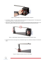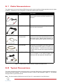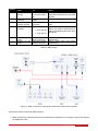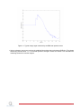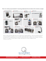
1
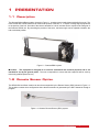
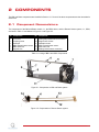
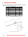
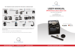
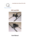
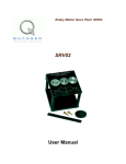
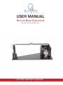
USER MANUAL
Ball and Beam Experiment
Set Up and Configuration
CAPTIVATE. MOTIVATE. GRADUATE.
c 2011 Quanser Inc., All rights reserved.
⃝
Quanser Inc.
119 Spy Court
Markham, Ontario
L3R 5H6
Canada
[email protected]
Phone: 1-905-940-3575
Fax: 1-905-940-3576
Printed in Markham, Ontario.
For more information on the solutions Quanser Inc. offers, please visit the web site at:
http://www.quanser.com
This document and the software described in it are provided subject to a license agreement. Neither the software nor this document may be
used or copied except as specified under the terms of that license agreement. All rights are reserved and no part may be reproduced, stored in
a retrieval system or transmitted in any form or by any means, electronic, mechanical, photocopying, recording, or otherwise, without the prior
written permission of Quanser Inc.
Waste Electrical and Electronic Equipment (WEEE)
This symbol indicates that waste products must be disposed of separately from municipal household waste, according to Directive
2002/96/EC of the European Parliament and the Council on waste electrical and electronic equipment (WEEE). All products at the
end of their life cycle must be sent to a WEEE collection and recycling center. Proper WEEE disposal reduces the environmental
impact and the risk to human health due to potentially hazardous substances used in such equipment. Your cooperation in proper
WEEE disposal will contribute to the effective usage of natural resources. For information about the available collection and
recycling scheme in a particular country, go to ni.com/citizenship/weee.
电子信息产品污染控制管理办法 (中国 RoHS)
中国客户 National Instruments 符合中国电子信息产品中限制使用某些有害物质命令 (RoHS)。
关于National Instruments 中国 RoHS合规性信息,请登录 ni.com/environment/rohs_china
(For information about China RoHS compliance, go to ni.com/environment/rohs_china)
This product meets the essential requirements of applicable European Directives as follows:
• 2006/95/EC; Low-Voltage Directive (safety)
• 2004/108/EC; Electromagnetic Compatibility Directive (EMC)
BB01 User Manual
2
CONTENTS
1
Presentation
1.1
Description
1.2
Remote Sensor Option
4
4
4
2
Components
2.1
Component Nomenclature
2.2
Component Description
5
5
6
3
Specifications
7
4
System Setup
8
5
Wiring Procedure
5.1
Cable Nomenclature
5.2
Typical Connections
10
11
11
6
Testing and Troubleshooting
6.1
SRV02 Motor and Encoder
6.2
Ball Position Sensor
14
14
14
7
Technical Support
16
BB01 User Manual
v 1.0
1
PRESENTATION
1.1 Description
The Quanser Ball and Beam module, pictured in Figure 1.1, consists a track on which the metal ball is free to roll. The
track is fitted with a linear transducer to measure the position of the ball, i.e., it outputs a voltage signal proportional
to the position of the ball. One side of the beam is attached to a lever arm that can be coupled to the load gear of
the Quanser SRV02 unit. By controlling the position of the servo, the beam angle can be adjusted to balance the
ball to a desired position.
Figure 1.1: Quanser BB01 system
Caution: This equipment is designed to be used for educational and research purposes and is not
intended for use by the general public. The user is responsible to ensure that the equipment will be used by
technically qualified personnel only.
1.2 Remote Sensor Option
The SRV02 Ball and Beam module can also be accompanied by the Remote Sensor (SS01) shown in Figure 1.2.
This enables a master-slave configuration where the ball command is generated by the SS01 instead of through a
program.
Figure 1.2: Quanser Remote Sensor (SS01) system
BB01 User Manual
4
2
COMPONENTS
The Ball and Beam components are identified in Section 2.1. Some of the those components are then described in
Section 2.2.
2.1 Component Nomenclature
The components of the Ball and Beam module, i.e., the BB01 device, and the Remote Sensor system, i.e., SS01,
are listed in Table 2.1 and labeled in Figure 2.1 and Figure 2.2.
ID
1
2
3
4
5
6
7
Component
SRV02
Lever arm
Coupling screw
Steel ball
BB01 Potentiometer sensor
BB01 Steel rod
Support arm
ID
8
9
10
11
12
13
14
Component
Support base
Analog ball position sensor connector
Support arm screws
Calibration base
SS01 Potentiometer sensor
SS01 Steel rod
Analog remote sensor connector
Table 2.1: Listing of BB01 and SS01 Components
Figure 2.1: Components on Ball and Beam system
Figure 2.2: Components on Remote Sensor system
BB01 User Manual
v 1.0
2.2 Component Description
2.2.1 Ball Position Sensor
The track of the BB01 linear transducer module on which the metal ball is free to roll consists of a steel rod in parallel
with a nickel-chromium wire-wound resistor forming the track. The resistive wire is the black strip that is stuck on
the plastic which is fastened onto the metal frame. The position of the ball is obtained by measuring the voltage at
the steel rod. When the ball rolls along the track, it acts as a wiper similar to a potentiometer resulting in the position
of the ball.
Caution: Regular cleaning of the beam is recommended to ensure proper operation of the ball and beam
experiment. Clean both the beam and the steel ball using rubbing alcohol.
2.2.2 Remote Sensor
Similarly to the BB01, the SS01 has a wiper potentiometer sensor that detects the position of the ball.
BB01 User Manual
6
3
SPECIFICATIONS
Table 3.1 lists and characterizes the main parameters associated with the BB01. See Figure 3.1 for an illustration
of the Ball and Beam dimensions and the variables α, θ, and x that are associated with the system. Some of the
parameters listed in Table 3.1 are used in the mathematical model.
Symbol
Lbeam
rarm
rb
mb
Kbs
Vbias
Vrange
Description
Mass of ball beam module
Calibration base length
Calibration base depth
Beam length
Lever arm length
Distance between SRV02 output
gear shaft and coupled joint
Support arm length
Radius of ball
Mass of ball
Ball position sensor sensitivity
Ball position sensor bias power
Ball position sensor measurement range
Matlab Variable
L beam
r arm
r ball
m ball
K BS
Value
0.65 kg
50 cm
22.5 cm
42.55 cm
12.0 cm
2.54 cm
16.0 cm
1.27 cm
0.064 kg
-4.25 cm/V
±12 V
±5 V
Table 3.1: Ball and Beam specifications
Figure 3.1: Ball and beam lengths and variables
BB01 User Manual
v 1.0
4
SYSTEM SETUP
This section describes how to setup the Quanser Ball and Beam (BB01) system for experimental use.
Caution: If the equipment is used in a manner not specified by the manufacturer, the protection provided by the
equipment may be impaired.
Caution: Exposed moving parts.
Follow this procedure to setup the Ball and Beam system:
1. Before beginning, ensure the SRV02 is setup in the high-gear configuration as detailed in SRV02 User Manual
[2].
2. Lay the calibration base, component #11 in Figure 2.1, flat on a table surface.
3. As pictured in Figure 4.1, place the SRV02 on its side such that the potentiometer gear fits into the cut-out
section of the calibration base.
Figure 4.1: Place SRV02 in calibration base
4. Place the support column of the Ball and Beam into the cut-out section of the calibration base, as shown in
Figure 4.2.
Figure 4.2: Place BB01 support column in calibration base
5. Tighten the coupling screw into the screw hole of the large 120-tooth load gear as depicted in Figure 4.3.
BB01 User Manual
8
Figure 4.3: Attach BB01 to SRV02 and rotate the gear to 0 degrees.
6. As illustrated in Figure 4.3, manually rotate the servo load gear to the 0 degree position. The coupling screw
should be aligned with the 0 degree position on the servo.
7. See Figure 4.4. While holding the load gear at 0 degrees, place the ball in the center of the beam and vary the
height of the support arm such that the beam is approximately horizontal and the ball does not move.
Figure 4.4: Adjust height of support column until ball is balanced at middle of beam
8. Tighten the 4x screws on the support arm, as illustrated in Figure 4.5, to finalize the calibration of the Ball and
Beam.
Figure 4.5: Tighten 4x screws on column to fix the height
BB01 User Manual
v 1.0
5
WIRING PROCEDURE
The following is a listing of the hardware components used in this experiment:
• Power Amplifier: Quanser VoltPAQ-X1, or equivalent.
• Data Acquisition Board: Quanser QPID, QPIDe, Q8-USB, Q2-USB, or equivalent.
• Rotary Servo Plant: Quanser SRV02-ET, SRV02-ETS, or equivalent.
• Ball and Beam: Quanser BB01 Module
• Remote Sensor: Quanser SS01 Module
See the corresponding documentation for more information on these components. The cables supplied with the
SRV02 are described in Section 5.1 and the procedure to connect the above components is given in Section 5.2.
Caution: When using the Quanser VoltPAQ-X1 power amplifier, make sure you set the Gain to 1!
BB01 User Manual
10
5.1 Cable Nomenclature
The cables used to connect the Quanser SRV02 system with a power amplifier and data-acquisition device is shown
in Table 5.1. Depending on your configuration, not all these cables may be necessary.
Cable
Type
2xRCA to 2xRCA
Description
This cable connects an analog output channel on the
data acquisition board to the power amplifier for amplification.
4-pin-DIN to 6-pin-DIN
This cable connects the output of the power amplifier
to the dc motor on the servo.
5-pin-stereo-DIN to 5pin-stereo-DIN
This cable carries the encoder signals between an
encoder connector and the data acquisition board (to
the encoder counter). Namely, these signals are: +5
VDC power supply, ground, channel A, and channel
B
6-pin-mini-DIN
6-pin-mini-DIN
This cable carries analog signals (e.g., from a potentiometer) to the amplifier, where the signals can
be either monitored and/or used by a controller. The
cable also carries a ± 12 VDC line from the amplifier
in order to power a sensor and/or signal conditioning
circuitry.
(a) RCA Cable
(b) Motor Cable
(c) Encoder Cable
to
(d) Analog Cable
5-pin-DIN to 4xRCA
This cable carries the analog signals, unchanged,
from the amplifier to the Analog-To-Digital input
channels on the data acquisition terminal board.
(e) 5-pin-DIN to 4xRCA
Table 5.1: Cables used to connect SRV02 to amplifier and DAQ device
5.2 Typical Connections
This section describes the typical connections used to connect the SRV02 plant to a data-acquisition board and a
single-channel power amplifier. The connections are given in Table 5.2 and illustrated in Figure 5.1. The detailed
wiring procedure is given below as well.
Note: The data acquisition (DAQ) device used in Figure 5.1 is representative for any DAQ device.
BB01 User Manual
v 1.0
Cable #
1
2
3
4
From
Terminal
DAC #0
Board:
Amplifier: To Load
connector
Terminal
Board:
Encoder Input #0
Amplifier: To ADC
connector
To
Amplifier Amplifier
Command connector
SRV02 Motor connector
SRV02
Encoder
connector
Terminal Board:
• S3 to ADC #0
• S4 to ADC #1
5
6
Amplifier S3 connector
Amplifier S4 connector
BB01 Ball Position
Sensor connector
SS01 Ball Position
Sensor connector
Signal
Connects control signal from Analog
Output #0 on DAQ device to the power
amplifier.
Power leads to the SRV02 dc motor.
Encoder load shaft angle measurement.
Connects BB01 and Remote Sensor
(SS01) ball position measurement to
analog input channels #0 and #1 on the
DAQ device.
Ball and Beam (BB01) ball position
measurement.
Remote Sensor (SS01) ball position
measurement.
Table 5.2: BB01 Wiring
Figure 5.1: BB01 connections using generic DAQ with a single-channel amplifier
Follow these steps to connect the SRV02 system:
1. Make sure that your data-acquisition device is installed and is operational. For example, see [3] if the Quanser
Q2-USB will be used.
BB01 User Manual
12
2. Make sure everything is powered off before making any of these connections. This includes turning off your
PC and the amplifier.
3. Connect one end of the 2xRCA to 2xRCA cable from the Analog Output Channel #0 on the terminal board
to the Amplifier Command connector on the amplifier, i.e. use both white or both red RCA connectors. See
cable #1 shown in Figure 5.1. This carries the attenuated motor voltage control signal, Vm /Ka , where Ka is
the amplifier gain.
4. Connect the 4-pin-stereo-DIN to 6-pin-stereo-DIN cable from To Load connector on the amplifier to the Motor
connector on the SRV02. See connection #2 shown in Figure 5.1. The cable transmits the amplified voltage
that is applied to the SRV02 motor and is denoted Vm .
5. Connect the 5-pin-stereo-DIN to 5-pin-stereo-DIN cable from the Encoder connector on the SRV02 panel to
Encoder Input # 0 on the terminal board, as depicted by connection #3 in Figure 5.1. This carries the load
shaft angle measurement and is denoted by the variable θl .
Note: In this setup, it is assumed the SRV02 encoder is used for position feedback (i.e., not using the
potentiometer).
Caution: Any encoder should be directly connected to the data-acquisition terminal board (or equivalent)
using a standard 5-pin DIN cable. DO NOT connect the encoder cable to the amplifier!
6. Connect the To ADC socket on the amplifier to Analog Inputs #0-1 on the terminal board using the 5-pin-DIN
to 4xRCA cable. Connect the red (S3) RCA connector to Analog Input Channel #0 and the black (S4) RCA
connector to Analog Input Channel #1. Note: The RCA cables may not be labeled S1, S2, S3, and S4. In
that case, use the colour convention yellow (S1), white (S2), red (S3), black (S4).
7. Connect the Ball Position Sensor connector from the BB01 to the S3 socket on the amplifier using the 6-pinmini-DIN to 6-pin-mini-DIN cable. See connection #5 in Figure 5.1. This carries the the measured ball position
from the beam potentiometer and is denoted by variable x.
8. If the SS01 remote sensor module (shown in Figure 2.2) is used, then connect Remote Ball Position Sensor
connector from the SS01 remote sensor module to the S4 socket on the amplifier using the 6-pin-mini-DIN to
6-pin-mini-DIN cable. See connection #6 in Figure 5.1. This measures the ball position on the remote sensor
and is denoted by xd .
BB01 User Manual
v 1.0
6
TESTING AND TROUBLESHOOTING
This section describes some functional tests to determine if the Ball and Beam system is operating properly. It is
assumed that the system is connected as described in the Section 5, above. To carry out these tests, it is preferable
if the user uses a software such as QUARCr or LabVIEWTM to read sensor measurements and ouput voltages to
the motor. See Reference [1] to learn how to interface the SRV02 with QUARC. Alternatively, these tests can be
performed with a signal generator and an oscilloscope.
6.1 SRV02 Motor and Encoder
See [2] for information on testing and troubleshooting the SRV02 separately.
6.2 Ball Position Sensor
6.2.1 Testing
Test the ball position sensor from the BB01 or SS01 with the following procedure:
1. Measure analog input channel #2 to test the BB01 sensor or analog input channel #3 to test the SS01 sensor
(unless the sensors are connected on a different channels).
2. A typical signal response of the ball position sensor is illustrated in Figure 6.1. For the BB01, the ball position
sensor should output a voltage of about 4.5 V when it is closest to the SRV02. As the ball is rolled away from
the SRV02 the measured voltage signal should be decreasing down to approximately -4.5 V when the ball
reaches the other end of the beam.
Caution: Sometimes when the ball is sitting at the very end of the beam it may not be in contact with the
sensor. In this case the reading will initially be 0 V but when the ball begins moving the sensor signal will jump
up to about 4.5 V and then begin decreasing.
3. Beside the ends of the beam, the signal should have no discontinuities and little noise. Similarly for the SS01
sensor, the voltage signal should decreasing from approximately 4.5 V to -4.5 V as the ball travels towards the
end of the beam with the analog connector.
6.2.2 Troubleshooting
Follow the steps below if the potentiometer is not measuring correctly:
• Verify that the power amplifier is functional. For example when using the Quanser VoltPAQ device, is the
green LED lit? Recall the analog sensor signal go through the amplifier before going to the data-acquisition
device (except when using the Q3 ControlPAQ). Therefore the amplifier needs to be turned on to read the
potentiometer.
• Check that the data-acquisition board is functional, e.g. ensure it is properly connected, that the fuse is not
burnt.
• Measure the voltage across the potentiometer. Ensure the potentiometer is powered with a ±12 V at the 6pin-mini DIN connector on the BB01, component #10 in Figure 2.1, or on the SS01, component #14 in Figure
2.2. The two bottom pins of the DIN connector are GND pins and the leftmost pin, i.e. where the green cable
is connected to, outputs the voltage of the ball.
BB01 User Manual
14
Figure 6.1: Typical voltage signal measured by the BB01 ball position sensor
• Using a voltmeter, connect one probe to the middle-left pin and the other to the bottom GND pins. The voltage
should vary between about ±4.5 V as the ball position is changed. Please see Section 7 for information on
contacting Quanser for technical support.
BB01 User Manual
v 1.0
7
TECHNICAL SUPPORT
To obtain support from Quanser, go to http://www.quanser.com/ and click on the Tech Support link. Fill in the form
with all the requested software and hardware information as well as a description of the problem encountered. Also,
make sure your e-mail address and telephone number are included. Submit the form and a technical support person
will contact you.
BB01 User Manual
16
REFERENCES
[1] Quanser Inc. SRV02 QUARC Integration, 2008.
[2] Quanser Inc. SRV02 User Manual, 2009.
[3] Quanser Inc. Q2-USB Data-Acquisition System User's Guide, 2010.
BB01 User Manual
v 1.0
Over ten rotary experiments for teaching fundamental and advanced controls concepts
Rotary Servo Base Unit
Flexible Joint
2 DOF Inverted
Pendulum
Ball and Beam
Double Inverted
Pendulum
2 DOF Gantry
Inverted
Pendulum
Gyro/Stable
Platform
Multi-DOF Torsion
Flexible Link
2 DOF Robot
2 DOF Ball
Balancer
Quanser’s rotary collection allows you to create experiments of varying complexity – from basic to advanced. Your lab
starts with the Rotary Servo Base Unit and is designed to help engineering educators reach a new level of efficiency
and effectiveness in teaching controls in virtually every engineering discipline including electrical, computer, mechanical,
aerospace, civil, robotics and mechatronics. For more information please contact [email protected].
©2012 Quanser Inc. All rights reserved.
[email protected]
+1-905-940-3575
Solutions for teaching and research. Made in Canada.
QUANSER.COM