1
INSTALLATION AND
OPERATION MANUAL
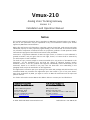
Vmux-210
Analog Voice Trunking Gateway
Version 1.1
Innovative Access Solutions
Vmux-210
Analog Voice Trunking Gateway
Version 1.1
Installation and Operation Manual
Notice
This manual contains information that is proprietary to RAD Data Communications Ltd. ("RAD").
No part of this publication may be reproduced in any form whatsoever without prior written
approval by RAD Data Communications.
Right, title and interest, all information, copyrights, patents, know-how, trade secrets and other
intellectual property or other proprietary rights relating to this manual and to the Vmux-210 and
any software components contained therein are proprietary products of RAD protected under
international copyright law and shall be and remain solely with RAD.
Vmux-210 is a registered trademark of RAD. No right, license, or interest to such trademark is
granted hereunder, and you agree that no such right, license, or interest shall be asserted by
you with respect to such trademark.
You shall not copy, reverse compile or reverse assemble all or any portion of the Manual or the
Vmux-210. You are prohibited from, and shall not, directly or indirectly, develop, market,
distribute, license, or sell any product that supports substantially similar functionality as the
Vmux-210, based on or derived in any way from the Vmux-210. Your undertaking in this
paragraph shall survive the termination of this Agreement.
This Agreement is effective upon your opening of the Vmux-210 package and shall continue until
terminated. RAD may terminate this Agreement upon the breach by you of any term hereof.
Upon such termination by RAD, you agree to return to RAD the Vmux-210 and all copies and
portions thereof.
For further information contact RAD at the address below or contact your local distributor.
International Headquarters
RAD Data Communications Ltd.
North America Headquarters
RAD Data Communications Inc.
24 Raoul Wallenberg Street
Tel Aviv 69719, Israel
Tel: 972-3-6458181
Fax: 972-3-6498250, 6474436
E-mail: [email protected]
900 Corporate Drive
Mahwah, NJ 07430, USA
Tel: (201) 5291100, Toll free: 1-800-4447234
Fax: (201) 5295777
E-mail: [email protected]
© 2003–2007 RAD Data Communications Ltd.
Publication No. 392-200-01/07
Limited Warranty
RAD warrants to DISTRIBUTOR that the hardware in the Vmux-210 to be delivered hereunder
shall be free of defects in material and workmanship under normal use and service for a period
of twelve (12) months following the date of shipment to DISTRIBUTOR.
If, during the warranty period, any component part of the equipment becomes defective by
reason of material or workmanship, and DISTRIBUTOR immediately notifies RAD of such defect,
RAD shall have the option to choose the appropriate corrective action: a) supply a replacement
part, or b) request return of equipment to its plant for repair, or c) perform necessary repair at
the equipment's location. In the event that RAD requests the return of equipment, each party
shall pay one-way shipping costs.
RAD shall be released from all obligations under its warranty in the event that the equipment has
been subjected to misuse, neglect, accident or improper installation, or if repairs or
modifications were made by persons other than RAD's own authorized service personnel, unless
such repairs by others were made with the written consent of RAD.
The above warranty is in lieu of all other warranties, expressed or implied. There are no
warranties which extend beyond the face hereof, including, but not limited to, warranties of
merchantability and fitness for a particular purpose, and in no event shall RAD be liable for
consequential damages.
RAD shall not be liable to any person for any special or indirect damages, including, but not
limited to, lost profits from any cause whatsoever arising from or in any way connected with the
manufacture, sale, handling, repair, maintenance or use of the Vmux-210, and in no event shall
RAD's liability exceed the purchase price of the Vmux-210.
DISTRIBUTOR shall be responsible to its customers for any and all warranties which it makes
relating to Vmux-210 and for ensuring that replacements and other adjustments required in
connection with the said warranties are satisfactory.
Software components in the Vmux-210 are provided "as is" and without warranty of any kind.
RAD disclaims all warranties including the implied warranties of merchantability and fitness for a
particular purpose. RAD shall not be liable for any loss of use, interruption of business or
indirect, special, incidental or consequential damages of any kind. In spite of the above RAD
shall do its best to provide error-free software products and shall offer free Software updates
during the warranty period under this Agreement.
RAD's cumulative liability to you or any other party for any loss or damages resulting from any
claims, demands, or actions arising out of or relating to this Agreement and the Vmux-210 shall
not exceed the sum paid to RAD for the purchase of the Vmux-210. In no event shall RAD be
liable for any indirect, incidental, consequential, special, or exemplary damages or lost profits,
even if RAD has been advised of the possibility of such damages.
This Agreement shall be construed and governed in accordance with the laws of the State of
Israel.
Product Disposal
To facilitate the reuse, recycling and other forms of recovery of waste
equipment in protecting the environment, the owner of this RAD product is
required to refrain from disposing of this product as unsorted municipal
waste at the end of its life cycle. Upon termination of the unit’s use,
customers should provide for its collection for reuse, recycling or other form
of environmentally conscientious disposal.
General Safety Instructions
The following instructions serve as a general guide for the safe installation and operation of
telecommunications products. Additional instructions, if applicable, are included inside the
manual.
Safety Symbols
This symbol may appear on the equipment or in the text. It indicates potential
safety hazards regarding product operation or maintenance to operator or service
personnel.
Warning
Danger of electric shock! Avoid any contact with the marked surface while the
product is energized or connected to outdoor telecommunication lines.
Protective earth: the marked lug or terminal should be connected to the building
protective earth bus.
Warning
Some products may be equipped with a laser diode. In such cases, a label with the
laser class and other warnings as applicable will be attached near the optical
transmitter. The laser warning symbol may be also attached.
Please observe the following precautions:
•
Before turning on the equipment, make sure that the fiber optic cable is intact
and is connected to the transmitter.
•
Do not attempt to adjust the laser drive current.
•
Do not use broken or unterminated fiber-optic cables/connectors or look
straight at the laser beam.
•
The use of optical devices with the equipment will increase eye hazard.
•
Use of controls, adjustments or performing procedures other than those
specified herein, may result in hazardous radiation exposure.
ATTENTION: The laser beam may be invisible!
In some cases, the users may insert their own SFP laser transceivers into the product. Users are
alerted that RAD cannot be held responsible for any damage that may result if non-compliant
transceivers are used. In particular, users are warned to use only agency approved products that
comply with the local laser safety regulations for Class 1 laser products.
Always observe standard safety precautions during installation, operation and maintenance of
this product. Only qualified and authorized service personnel should carry out adjustment,
maintenance or repairs to this product. No installation, adjustment, maintenance or repairs
should be performed by either the operator or the user.
Handling Energized Products
General Safety Practices
Do not touch or tamper with the power supply when the power cord is connected. Line voltages
may be present inside certain products even when the power switch (if installed) is in the OFF
position or a fuse is blown. For DC-powered products, although the voltages levels are usually
not hazardous, energy hazards may still exist.
Before working on equipment connected to power lines or telecommunication lines, remove
jewelry or any other metallic object that may come into contact with energized parts.
Unless otherwise specified, all products are intended to be grounded during normal use.
Grounding is provided by connecting the mains plug to a wall socket with a protective earth
terminal. If an earth lug is provided on the product, it should be connected to the protective
earth at all times, by a wire with a diameter of 18 AWG or wider. Rack-mounted equipment
should be mounted only in earthed racks and cabinets.
Always make the ground connection first and disconnect it last. Do not connect
telecommunication cables to ungrounded equipment. Make sure that all other cables are
disconnected before disconnecting the ground.
Connecting AC Mains
Make sure that the electrical installation complies with local codes.
Always connect the AC plug to a wall socket with a protective ground.
The maximum permissible current capability of the branch distribution circuit that supplies power
to the product is 16A. The circuit breaker in the building installation should have high breaking
capacity and must operate at short-circuit current exceeding 35A.
Always connect the power cord first to the equipment and then to the wall socket. If a power
switch is provided in the equipment, set it to the OFF position. If the power cord cannot be
readily disconnected in case of emergency, make sure that a readily accessible circuit breaker or
emergency switch is installed in the building installation.
In cases when the power distribution system is IT type, the switch must disconnect both poles
simultaneously.
Connecting DC Mains
Unless otherwise specified in the manual, the DC input to the equipment is floating in reference
to the ground. Any single pole can be externally grounded.
Due to the high current capability of DC mains systems, care should be taken when connecting
the DC supply to avoid short-circuits and fire hazards.
DC units should be installed in a restricted access area, i.e. an area where access is authorized
only to qualified service and maintenance personnel.
Make sure that the DC supply is electrically isolated from any AC source and that the installation
complies with the local codes.
The maximum permissible current capability of the branch distribution circuit that supplies power
to the product is 16A. The circuit breaker in the building installation should have high breaking
capacity and must operate at short-circuit current exceeding 35A.
Before connecting the DC supply wires, ensure that power is removed from the DC circuit. Locate
the circuit breaker of the panel board that services the equipment and switch it to the OFF
position. When connecting the DC supply wires, first connect the ground wire to the
corresponding terminal, then the positive pole and last the negative pole. Switch the circuit
breaker back to the ON position.
A readily accessible disconnect device that is suitably rated and approved should be incorporated
in the building installation.
If the DC mains are floating, the switch must disconnect both poles simultaneously.
Connecting Data and Telecommunications Cables
Data and telecommunication interfaces are classified according to their safety status.
The following table lists the status of several standard interfaces. If the status of a given port
differs from the standard one, a notice will be given in the manual.
Ports
Safety Status
V.11, V.28, V.35, V.36, RS-530, X.21,
10 BaseT, 100 BaseT, Unbalanced E1,
E2, E3, STM, DS-2, DS-3, S-Interface
ISDN, Analog voice E&M
SELV
xDSL (without feeding voltage),
Balanced E1, T1, Sub E1/T1
TNV-1 Telecommunication Network Voltage-1:
FXS (Foreign Exchange Subscriber)
TNV-2 Telecommunication Network Voltage-2:
Ports whose normal operating voltage exceeds the
limits of SELV (usually up to 120 VDC or telephone
ringing voltages), on which overvoltages from
telecommunication networks are not possible. These
ports are not permitted to be directly connected to
external telephone and data lines.
FXO (Foreign Exchange Office), xDSL
(with feeding voltage), U-Interface
ISDN
TNV-3 Telecommunication Network Voltage-3:
Ports whose normal operating voltage exceeds the
limits of SELV (usually up to 120 VDC or telephone
ringing voltages), on which overvoltages from
telecommunication networks are possible.
Safety Extra Low Voltage:
Ports which do not present a safety hazard. Usually
up to 30 VAC or 60 VDC.
Ports whose normal operating voltage is within the
limits of SELV, on which overvoltages from
telecommunications networks are possible.
Always connect a given port to a port of the same safety status. If in doubt, seek the assistance
of a qualified safety engineer.
Always make sure that the equipment is grounded before connecting telecommunication cables.
Do not disconnect the ground connection before disconnecting all telecommunications cables.
Some SELV and non-SELV circuits use the same connectors. Use caution when connecting cables.
Extra caution should be exercised during thunderstorms.
When using shielded or coaxial cables, verify that there is a good ground connection at both
ends. The earthing and bonding of the ground connections should comply with the local codes.
The telecommunication wiring in the building may be damaged or present a fire hazard in case of
contact between exposed external wires and the AC power lines. In order to reduce the risk,
there are restrictions on the diameter of wires in the telecom cables, between the equipment
and the mating connectors.
Caution
To reduce the risk of fire, use only No. 26 AWG or larger telecommunication line
cords.
Attention
Pour réduire les risques s’incendie, utiliser seulement des conducteurs de
télécommunications 26 AWG ou de section supérieure.
Some ports are suitable for connection to intra-building or non-exposed wiring or cabling only. In
such cases, a notice will be given in the installation instructions.
Do not attempt to tamper with any carrier-provided equipment or connection hardware.
Electromagnetic Compatibility (EMC)
The equipment is designed and approved to comply with the electromagnetic regulations of
major regulatory bodies. The following instructions may enhance the performance of the
equipment and will provide better protection against excessive emission and better immunity
against disturbances.
A good earth connection is essential. When installing the equipment in a rack, make sure to
remove all traces of paint from the mounting points. Use suitable lock-washers and torque. If an
external grounding lug is provided, connect it to the earth bus using braided wire as short as
possible.
The equipment is designed to comply with EMC requirements when connecting it with unshielded
twisted pair (UTP) cables. However, the use of shielded wires is always recommended, especially
for high-rate data. In some cases, when unshielded wires are used, ferrite cores should be
installed on certain cables. In such cases, special instructions are provided in the manual.
Disconnect all wires which are not in permanent use, such as cables used for one-time
configuration.
The compliance of the equipment with the regulations for conducted emission on the data lines
is dependent on the cable quality. The emission is tested for UTP with 80 dB longitudinal
conversion loss (LCL).
Unless otherwise specified or described in the manual, TNV-1 and TNV-3 ports provide secondary
protection against surges on the data lines. Primary protectors should be provided in the building
installation.
The equipment is designed to provide adequate protection against electro-static discharge (ESD).
However, it is good working practice to use caution when connecting cables terminated with
plastic connectors (without a grounded metal hood, such as flat cables) to sensitive data lines.
Before connecting such cables, discharge yourself by touching earth ground or wear an ESD
preventive wrist strap.
FCC-15 User Information
This equipment has been tested and found to comply with the limits of the Class A digital device,
pursuant to Part 15 of the FCC rules. These limits are designed to provide reasonable protection
against harmful interference when the equipment is operated in a commercial environment. This
equipment generates, uses and can radiate radio frequency energy and, if not installed and used
in accordance with the Installation and Operation manual, may cause harmful interference to the
radio communications. Operation of this equipment in a residential area is likely to cause harmful
interference in which case the user will be required to correct the interference at his own
expense.
Canadian Emission Requirements
This Class A digital apparatus meets all the requirements of the Canadian Interference-Causing
Equipment Regulation.
Cet appareil numérique de la classe A respecte toutes les exigences du Règlement sur le matériel
brouilleur du Canada.
Warning per EN 55022 (CISPR-22)
Warning
Avertissement
Achtung
This is a class A product. In a domestic environment, this product may cause radio
interference, in which case the user will be required to take adequate measures.
Cet appareil est un appareil de Classe A. Dans un environnement résidentiel, cet
appareil peut provoquer des brouillages radioélectriques. Dans ces cas, il peut être
demandé à l’utilisateur de prendre les mesures appropriées.
Dieses ist ein Gerät der Funkstörgrenzwertklasse A. In Wohnbereichen können bei
Betrieb dieses Gerätes Rundfunkströrungen auftreten, in welchen Fällen der
Benutzer für entsprechende Gegenmaßnahmen verantwortlich ist.
Declaration of Conformity
Manufacturer's Name:
RAD Data Communications Ltd.
Manufacturer's Address:
24 Raoul Wallenberg St.
Tel Aviv 69719
Israel
Declares that the product:
Product Name:
Vmux-210
conforms to the following standard(s) or other normative document(s):
EMC:
EN 55022:1998 +
Information technology equipment – Radio disturbance
A1:2000, A2:2003
characteristics – Limits and methods of measurement.
EN 55024:1998 +
Information technology equipment – Immunity characteristics
A1:2001, A2:2003
Safety:
EN 60950-1:2001
– Limits and methods of measurement.
Information technology equipment – Safety – Part 1: General
requirements.
Supplementary Information:
The product herewith complies with the requirements of the EMC Directive 89/336/EEC, the Low
Voltage Directive 73/23/EEC and the R&TTE Directive 99/5/EC for wired equipment. The product
was tested in a typical configuration.
Tel Aviv, 14 March, 2006
Haim Karshen
VP Quality
European Contact: RAD Data Communications GmbH, Otto-Hahn-Str. 28-30, 85521
Ottobrunn-Riemerling, Germany
Quick Start Guide
Installation of Vmux-210 should be carried out only by an experienced technician.
If you are familiar with Vmux-210, use this guide to prepare the unit for
operation.
1.
Installing Vmux-210
Connecting the Interfaces
Refer to Appendix A for pinouts and further information regarding interface
connections.
To connect the interfaces:
1. Connect FXS voice interface to the connector on the Vmux-210 rear panel
labeled Channels 1-x.
2. Connect the main link using the appropriate connector, as follows:
Ethernet main link: Connect the IP uplink to the RJ-45 connector
designated NET ETH.
Serial main link: Connect the serial V.35/X.21/RS-530 link to the DB-25
connector designated LINK using the appropriate adapter cable.
E1/T1 main link: Connect the E1/T1 main link to the RJ-45 connector on
the Vmux-210 rear panel, designated E1/T1.
3. Connect the user LAN to the RJ-45 connector designated ETH USER.
4. Connect the control terminal to the CONTROL connector using CBL-RJ45/D9
adapter cable.
or
Connect a Telnet host to the user LAN port.
Connecting the Power
To connect the power:
•
Connect the power cable to the power connector on the Vmux-210 rear
panel.
The unit has no power switch. Operation starts when the power is applied
to the rear panel power connector.
Vmux-210 Ver. 1.1
Installing Vmux-210
1
Quick Start Guide
Installation and Operation Manual
2.
Configuring Vmux-210
Configure Vmux-210 to the desired operation mode via an ASCII terminal connected
to the rear panel CONTROL port. Alternatively, you can manage Vmux-210 over
Telnet.
Starting a Terminal Session for the First Time
To start a terminal session:
1. Connect a terminal to the CONTROL connector of Vmux-210.
2. Turn on the control terminal PC and set its port parameters the default
communication parameters:
One start bit
Eight data bits
No parity
One stop bit
No flow control
VT100 emulation (for optimal view of system menus).
3. Power up Vmux-210.
4. After the boot sequence (approximately 50 seconds), press <Enter> several
times.
The rate is detected automatically.
5. Proceed with the management session.
Configuring Basic Parameters
The host IP address, subnet mask and default gateway IP address must be
configured via an ASCII terminal.
To configure basic parameters:
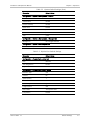
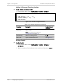
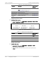
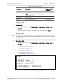
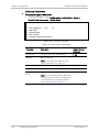
1. From the Main Menu, select Configuration > Quick Setup.
The Quick Setup menu appears (see Figure 1).
2. Configure the desired parameters (see Table 1).
3. Select Save.
4. Type ‘@’ and press <Enter>.
The following message is displayed:
Are you sure you want to update data base?
Press Y/N :
2
Configuring Vmux-210
Vmux-210 Ver. 1.1
Installation and Operation Manual
Quick Start Guide
5. Type Y to update the database.
The database is updated and the following message is displayed:
Data base was changed. Press any key to continue.
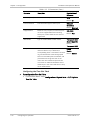
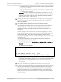
Quick Setup
1.
2.
3.
4.
5.
6.
Host IP Address … (0.0.0.0)
Host Subnet Mask … (0.0.0.0)
Default Gateway … (0.0.0.0)
Destination IP … (0.0.0.0)
Destination Bundle [1 – 30] … (1)
Save
Figure 1. Quick Setup Menu
Table 1. Quick Setup Parameters
Parameter
Description
Possible Values/
Reference
Host IP Address
Defines Vmux-210’s IP address (for both
management and voice traffic)
Default: 0.0.0.0
Host Subnet Mask
Defines Vmux-210’s subnet mask
Default: 0.0.0.0
Default Gateway
Defines default gateway
Default: 0.0.0.0
Destination IP
IP address of the destination Vmux-2100
group or Vmux-210/110
Default: 0.0.0.0
Destination Bundle
Number of the destination bundle
1..30
Default: 1
Save
Configures a basic voice application in the
temporary DB, including a single bundle
(according to the specified Destination IP
and Destination Bundle); all other
parameters retain default values, including
the analog ports connected to this bundle
Notes:
Vmux-210 Ver. 1.1
•
The Save command erases previously
configured bundles (in the event that
bundles were configured manually
through the Bundles menu).
•
In addition to selecting Save, you must
press @ to save the changes in the
database. Otherwise, all changes will be
lost.
Configuring Vmux-210
3
Quick Start Guide
4
Configuring Vmux-210
Installation and Operation Manual
Vmux-210 Ver. 1.1
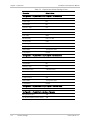
Contents
Chapter 1. Introduction
1.1
Overview....................................................................................................................1-1
Product Options......................................................................................................1-1
Applications............................................................................................................1-2
Features .................................................................................................................1-3
Ethernet Links.................................................................................................................. 1-3
Serial Main Link................................................................................................................ 1-3
Voice Interfaces ............................................................................................................... 1-3
TDMoIP Multiplexing......................................................................................................... 1-3
AAL2oMPLS Multiplexing .................................................................................................. 1-3
Bundling .......................................................................................................................... 1-4
Internal Switch and VLAN Tagging for Security and QoS................................................... 1-4
VLAN Table ...................................................................................................................... 1-4
Internal Router ................................................................................................................ 1-4
Diagnostics ...................................................................................................................... 1-5
Statistics Collection.......................................................................................................... 1-5
Management.................................................................................................................... 1-5
1.2
1.3
Physical Description ...................................................................................................1-6
Functional Description................................................................................................1-7
Voice Interface .......................................................................................................1-9
Signaling .......................................................................................................................... 1-9
Compression .................................................................................................................... 1-9
Voice Activity Detection ................................................................................................. 1-10
TDMoIP Multiplexing....................................................................................................... 1-10
Ethernet Frame.............................................................................................................. 1-10
VLAN Support (per bundle) ............................................................................................ 1-12
UDP Support .................................................................................................................. 1-12
E1/T1/Serial Main Link...........................................................................................1-13
Ethernet Main Link (ETH NET Port) ........................................................................1-13
Ethernet User LAN (ETH USER Port).......................................................................1-13
Rate Limiting on Ethernet ports ............................................................................1-13
Integral Ethernet Switch........................................................................................1-13
VLAN Tagging on Ethernet and E1/T1/Serial Ports .......................................................... 1-13
VLAN Table .................................................................................................................... 1-14
1.4
DHCP Client Support .............................................................................................1-14
Calculating Approximate Bandwidth Utilization ......................................................1-14
Bandwidth Utilization when using TDMoIP .............................................................1-14
Bandwidth Utilization when using AAL2oMPLS.......................................................1-16
Technical Specifications............................................................................................1-17
Chapter 2. Installation and Setup
2.1
2.2
2.3
2.4
2.5
2.6
2.7
Introduction...............................................................................................................2-1
Site Requirements and Prerequisites ..........................................................................2-2
Package Contents ......................................................................................................2-2
Equipment Needed.....................................................................................................2-2
Power Cable............................................................................................................2-2
Interface Cables......................................................................................................2-2
Mounting the Unit......................................................................................................2-3
Connecting to the FXS Voice Port ...............................................................................2-3
Connecting to the Main Link.......................................................................................2-4
Connecting to the Ethernet Main Link .....................................................................2-4
Vmux-210 Ver. 1.1
i
Table of Contents
Installation and Operation Manual
Connecting to the Serial Main Link ..........................................................................2-4
Connecting to the E1 Link .......................................................................................2-4
Connecting to the T1 Link .......................................................................................2-5
2.8 Connecting to the User LAN Port ................................................................................2-5
2.9 Connecting to the ASCII Terminal................................................................................2-6
2.10 Connecting to Power..................................................................................................2-6
Connecting to AC Power..........................................................................................2-6
Connecting to DC Power .........................................................................................2-7
Chapter 3. Operation
3.1
3.2
3.3
3.4
Turning On the Unit ...................................................................................................3-1
Indicators ..................................................................................................................3-2
Default Settings .........................................................................................................3-2
Configuration and Management Alternatives ..............................................................3-8
Working with an ASCII Terminal ...............................................................................3-8
Initiating a Control Session .............................................................................................. 3-8
Logging In ........................................................................................................................ 3-9
Navigating the Management Menus ............................................................................... 3-10
Using Terminal Hot Keys ................................................................................................ 3-11
Sample Help Screen ....................................................................................................... 3-11
Security Levels ............................................................................................................... 3-11
Working with Telnet..............................................................................................3-12
Working with ConfiguRAD .....................................................................................3-12
Web Browser Requirements........................................................................................... 3-13
Logging in via a Web Browser ........................................................................................ 3-13
Navigating the ConfiguRAD Menus ................................................................................. 3-13
Navigating the Management Menus ......................................................................3-14
Choosing Parameters ..................................................................................................... 3-14
Saving and Aborting Configuration Changes................................................................... 3-14
3.5
Menu Map ............................................................................................................3-15
Turning Off the Unit.................................................................................................3-19
Chapter 4. Configuration
4.1
4.2
Configuring for Management ......................................................................................4-1
Setting Host IP Parameters .....................................................................................4-4
Configuring the Manager List ..................................................................................4-4
Managing Users ......................................................................................................4-5
Configuring for Operation ..........................................................................................4-6
Configuring Physical Ports .......................................................................................4-6
Configuring
Configuring
Configuring
Configuring
the Ethernet Port .......................................................................................... 4-7
the Serial Uplink ............................................................................................ 4-8
the E1/T1 Uplink.......................................................................................... 4-10
Analog Ports ............................................................................................... 4-15
Configuring Bundles ..............................................................................................4-18
Displaying all Bundles..................................................................................................... 4-19
Adding, Editing and Deleting Bundles............................................................................. 4-20
Configuring a Bundle’s Channel Distribution................................................................... 4-31
Configuring the Bridge ..........................................................................................4-34
Configuring VLAN ..................................................................................................4-35
Displaying the VLAN Table.............................................................................................. 4-36
Adding and Editing a VLAN............................................................................................. 4-36
Deleting a VLAN ............................................................................................................. 4-37
Configuring the Router..........................................................................................4-38
Configuring Router Interfaces ........................................................................................ 4-38
Configuring the Router Uplink Port ................................................................................ 4-39
ii
Vmux-210 Ver. 1.1
Installation and Operation Manual
Table of Contents
Configuring the Router Network Port............................................................................. 4-40
Configuring the Router User Port ................................................................................... 4-41
Configuring Static Routing ............................................................................................. 4-45
Configuring the Default Gateway...........................................................................4-48
Configuring DHCP Server .......................................................................................4-48
Adding a DHCP Server Pool ............................................................................................ 4-49
Editing a DHCP Server Pool............................................................................................. 4-49
Deleting a DHCP Server Pool .......................................................................................... 4-50
Configuring Network Address Translation (NAT) ....................................................4-50
Adding a NAT ................................................................................................................. 4-51
Editing a NAT ................................................................................................................. 4-51
Deleting a NAT............................................................................................................... 4-54
4.3
Setting Global Firewall Parameters ........................................................................4-55
Additional Tasks.......................................................................................................4-59
Displaying the Vmux-210 Inventory .......................................................................4-59
Downloading Software via XMODEM or TFTP .........................................................4-59
Boot Sequence .............................................................................................................. 4-60
Accessing the File System .............................................................................................. 4-60
Uploading/Downloading Files via XMODEM..................................................................... 4-61
Downloading Application Files using a TFTP Server......................................................... 4-62
Uploading/Downloading Files from the System Menu..................................................... 4-63
Restoring Default Settings ....................................................................................4-64
Setting the Date and Time ....................................................................................4-65
Configuring Alarm LED Activation Level..................................................................4-66
Resetting Vmux-210 .............................................................................................4-67
Chapter 5. Configuring Vmux-210 for a Typical Application
5.1
5.2
5.3
5.4
5.5
Application Requirements...........................................................................................5-1
Configuration Sequence .............................................................................................5-2
Configuring the Local Vmux-2100 ...............................................................................5-2
Configuring Vmux-210................................................................................................5-4
Configuring System Parameters...............................................................................5-4
Configuring Analog Voice Parameters ......................................................................5-5
Transferring Database to the Second Vmux-210 .........................................................5-6
Chapter 6. Troubleshooting and Diagnostics
6.1
Monitoring Performance.............................................................................................6-1
Viewing Statistics....................................................................................................6-1
Monitoring Bundles.................................................................................................6-2
Displaying Bundle Statistics ............................................................................................. 6-2
Tracking Packets .............................................................................................................. 6-4
6.2
6.3
6.4
6.5
Displaying Timeslot Voice Statistics .........................................................................6-6
Displaying Analog Signaling Statistics ......................................................................6-8
Displaying E1/T1 and Serial Uplink Statistics ............................................................6-8
Displaying Ethernet Statistics ................................................................................6-10
Clearing all Statistics .............................................................................................6-12
Detecting Errors.......................................................................................................6-12
Handling Alarms .......................................................................................................6-14
Alarm Buffer .........................................................................................................6-14
Working with the Temporary Alarm Buffer.............................................................6-14
List of Vmux-210 Alarms .......................................................................................6-15
General Troubleshooting ..........................................................................................6-16
Testing Vmux-210 ....................................................................................................6-17
Tone Injection.......................................................................................................6-17
Vmux-210 Ver. 1.1
iii
Table of Contents
Installation and Operation Manual
Loopback Tests.....................................................................................................6-19
Remote Loopbacks on an Analog Channel...................................................................... 6-20
Remote Loopbacks on an E1/T1 Uplink .......................................................................... 6-20
6.6
6.7
Pinging Remote Devices ........................................................................................6-20
Displaying the Active Tests....................................................................................6-21
Frequently Asked Questions .....................................................................................6-21
Technical Support ....................................................................................................6-26
Appendix A. Connector Pinouts
iv
Vmux-210 Ver. 1.1
Chapter 1
Introduction
1.1
Overview
Vmux-210 is a voice trunking gateway that enables several analog voice channels
to be compressed and extended over a serial, E1/T1 or 10/100BaseT uplink.
Vmux-210 implements G.723.1, G.729 A, G.711 compression and TDMoIP or
AAL2oMPLS multiplexing algorithms to send 12, 15, 24 or 30 analog voice
channels over an IP, E1/T1 or n x 64 kbps network.
Vmux-210 utilizes voice activity detection, silence suppression, echo cancellation
and other techniques to improve voice quality and bandwidth utilization. The
gateway detects, generates and relays DTMF signaling. In addition, Vmux-210
supports fax relay, modem relay and voice band data.
The built-in router supports NAT, firewall, static and dynamic routing, RIP1 and
RIP2. To facilitate the integration of new devices into a DHCP IP network, the
router also supports DHCP client, server and relay.
Vmux-210 can be managed locally via an ASCII terminal or remotely via Telnet or
RADview (RAD’s SNMP-based network management application).
Product Options
Vmux-210 can be ordered with the following options:
Voice port options:
•
12 FXS ports for up to 12 channels
•
15 FXS ports for up to 15 channels
•
24 FXS ports for up to 24 channels
•
30 FXS ports for up to 30 channels.
Uplink options:
Vmux-210 Ver. 1.1
•
E1 uplink
•
T1 uplink
•
Serial
•
Ethernet.
Overview
1-1
Chapter 1 Introduction
Installation and Operation Manual
Cable options for the Serial Link:
•
V.35, DCE
•
V.35, DTE
•
X.21, DCE
•
X.21, DTE
•
RS-530, DTE.
RS-530, DTE
Note
An adapter cable is not required for connecting to RS-530 equipment when
Vmux-210 operates in DCE clock mode.
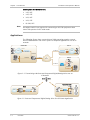
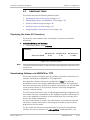
Applications
The following figures show a central Vmux-2100 operating opposite remote
Vmux-2100 and Vmux-210 units in point-to-multipoint applications over an IP
network.
Central Site
Site A
E1/T1s
PSTN
E1/T1s
10/100BaseT
Vmux-2100
PSTN
Vmux-2100
Digital
Voice
10/100BaseT
10/100BaseT
10/100BaseT
IP
Network
Site B
FXS
Router
Ethernet
LAN
Up to
30 FXS
Analog
Voice
10/100BaseT
Vmux-210
10/100BaseT
Data
Ethernet
LAN
Figure 1-1. Transmitting LAN Data and Compressed Digital/Analog Voice over an
IP Network
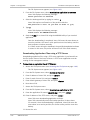
Remote Call Center
Site A
FXS
E1/T1
PSTN
PBX or Telephony
Switch
Vmux-2100
Up to
30 FXS
E1/T1
Vmux-210
FXS
Figure 1-2. Data and Compressed Digital/Analog Voice for Call Center Application
1-2
Overview
Vmux-210 Ver. 1.1
Installation and Operation Manual
Chapter 1 Introduction
Features
Ethernet Links
Vmux-210 provides two half/full duplex, 10/100BaseT Ethernet ports, each with
autonegotiation support. One port can function as the uplink to the IP network,
while the other is provided for connecting the user Ethernet LAN to the
Vmux-210 unit. Together with the Vmux-210's integral Ethernet switch, this
allows integrating the user LAN traffic with the compressed voice, over a single
uplink to the network.
If autonegotiation is disabled, the Ethernet ports can be configured to any of the
following operation modes:
•
10BaseT – half or full duplex
•
100BaseT – half or full duplex.
The main link Ethernet port supports direct and indirect connection to the IP
network.
Serial Main Link
Vmux-210 has a single TDM Serial Link with a RS-530/DCE interface. This serial
port supports n x 64 kbps data rates, from 64 to 2048 kbps. Additional serial
interfaces are supported via adapter cables. For more information, see Product
Options on page 1-1.
Voice Interfaces
Vmux-210 is ordered with 12, 15, 24, or 30 analog voice interfaces.
Voice Activity Detection mechanism allows optimizing bandwidth utilization, as
Vmux-210 generates traffic only when voice activity is detected. Vmux-210 uses
the G.723.1 and G.729A voice compression techniques, silence suppression and
the G.168 standard for echo cancellation (echo tail up to 32 ms per channel).
Vmux-210 detects, relays, and generates DTMF signals. In addition, Vmux-210
supports Group III fax relay (4.8, 9.6, 14.4 kbps), modem relay (up to V.34), and
voiceband data.
TDMoIP Multiplexing
Vmux-210 encapsulates the payload bytes in a UDP frame that is transferred over
IP and over Ethernet.
The maximum number of TDM bytes in a multiplexed frame and maximum
packetizing interval are user-configurable.
A destination IP address is configured for each bundle (see Bundling on
page 1-4).
AAL2oMPLS Multiplexing
When using non-IP based Ethernet networks or the E1/T1/Serial uplink, the
AAL2oMPLS format can be used instead of TDMoIP. The AAL2oMPLS header is
Vmux-210 Ver. 1.1
Overview
1-3
Chapter 1 Introduction
Installation and Operation Manual
smaller than the TDMoIP header, saving about 5% in bandwidth (depending on
the actual frame size).
Bundling
A bundle is a logical internal Vmux-210 port, containing up to 30 timeslots.
Vmux-210 supports 12 bundles. A bundle is routed to a defined remote IP
address. Each timeslot can be included in any bundle. At the remote site, it can
be connected to any timeslot within a destination bundle.
Bundle QoS supports:
•
Labeling IP level priority (ToS).
•
VLAN tagging and priority labeling according to IEEE 802.1D&Q.
The user can configure the ToS (Type of Service) of the outgoing IP packets. This
allows an en-route layer 3 router or switch that supports ToS to give higher
priority to Vmux-210 traffic for delay-sensitive and secure applications.
Vmux-210 allows you to configure the whole ToS byte field, since different
vendors may use different bits to tag packets for traffic prioritization. This also
enables you to work according to various RFC definitions (for example RFC 2474,
RFC 791).
Internal Switch and VLAN Tagging for Security and QoS
All traffic between:
•
Ethernet ports
•
Ethernet port and voice port
•
Ethernet port and E1/T1/Serial Uplink
•
Ethernet port and the host
is routed through the Vmux-210’s built-in Ethernet switch. This switch enables
optional VLAN tagging of the various traffic, as well as blocking unrecognized
traffic.
VLAN Table
Vmux-210 includes a VLAN table, which can contain up to 64 entries. Each entry
defines the egress and tagging policies for packets with a specific VLAN ID, for
each port. Packets with a particular VLAN ID can be blocked.
Internal Router
Vmux-210 includes an internal router, which supports the following features:
1-4
•
DHCP server, client, or relay
•
NAT
•
Firewall
•
Static and dynamic routing
•
RIP1 and RIP2.
Overview
Vmux-210 Ver. 1.1
Installation and Operation Manual
Chapter 1 Introduction
When the internal router is enabled, it performs the routing between the
Ethernet ports and the E1/T1/Serial Link (whichever is defines as the main link),
or between the two Ethernet ports. If the internal router is disabled, the Ethernet
switch performs the Ethernet switching, while voice traffic is routed directly from
the Host to the DSPs. The various features of the internal router are
configurable.
Diagnostics
Vmux-210 supports remote loopback activation on the analog voice channels. The
user can also perform tone injection towards the remote PBX or local/remote
analog equipment. In addition, a ping utility is included to confirm IP connectivity
to the remote units.
Statistics Collection
Vmux-210 provides extensive statistics collection capabilities, which include
Ethernet (as per RFC 3638) and HDLC statistics, voice, signaling, bundles, and CPU
utilization.
Management
Vmux-210 can be managed via a local terminal, HTTP Web browser, Telnet or
RADview (RAD’s network management system). Vmux-210 has a DB-9 port for
the direct terminal connection.
Software download and configuration upload/download can be performed via the
local terminal or TFTP (using a TFTP server). Remote units are managed via Telnet
or RADview over an inband management link.
Vmux-210 supports a four-level security and user-authentication system:
•
Administrator – Allowed to configure all the Vmux-210 parameters.
•
Operator – Allowed to perform all operations in the system except for user
administration (adding/deleting users, changing user definitions).
•
Technician – Allowed to test Vmux-210 and monitor its operation (for
example, monitoring alarms).
•
Monitor – Allowed to monitor the Vmux-210 operation.
When Vmux-210 is managed over Telnet or a Web browser, up to five
simultaneous management sessions are allowed, as follows:
•
One administrator or operator
•
Up to four monitors.
Access to the Vmux-210 software can be limited to the ASCII terminal and
RADview management by disabling Telnet/Web access.
Vmux-210 Ver. 1.1
Overview
1-5
Chapter 1 Introduction
Installation and Operation Manual
1.2
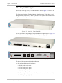
Physical Description
Vmux-210 is a 1U high, easy-to-install standalone device. Figure 1-3 shows a 3D
view of the unit.
The front panel includes LEDs that indicate when the power is ON, when a test is
being performed, and when an alarm is present in the system. LEDs are described
in greater detail in Chapter 3.
Figure 1-3. Vmux-210, Front Panel 3D
The rear panel varies depending on the port and power supply options. Figure 1-5
shows the rear panel of a Vmux-210 with the AC power supply option.
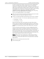
Figure 1-4. Vmux-210, Rear Panel 3D
Vmux-210
USE
R
CHANNELS 1-30
ETH
E1/
T1
NET
SERIAL
LINK
CONTROL
PWR
TST
ALM
LINK
AC
T
LINK
AC
T
Figure 1-5. Rear Panel of Vmux-210 with AC Power Supply
The Vmux-210 rear panel includes the following:
•
One of the following voice interfaces:
12 FXS analog voice ports
15 FXS analog voice ports
24 FXS analog voice ports
30 FXS analog voice ports
1-6
•
Two Ethernet ports (one for the main link, one to connect to the user LAN)
•
One E1/T1 Uplink port (RJ-45)
Physical Description
Vmux-210 Ver. 1.1
Installation and Operation Manual
Chapter 1 Introduction
•
One serial uplink (DB-25 interface; used to connect to a TDM link via a serial
adapter cable)
•
One control port (DB-9 interface; used to connect to a management terminal)
•
One power supply (either AC or DC)
1.3
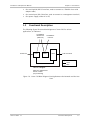
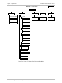
Functional Description
The following figures illustrate block diagrams of Vmux-210 for various
applications, as indicated.
10/100BaseT
Network Port
(Main Link)
10/100BaseT
User Port
Main Board
Control Port
Host
Router
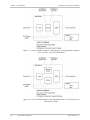
DSPs
FXS Voice Ports
Legend
Voice
Data
How to configure:
Main Link = Ethernet Port
Router = Enable
(Layer 3 Routing)
Figure 1-6. Vmux-210 Block Diagram: Routing Between the Network and the User
Ports
Vmux-210 Ver. 1.1
Functional Description
1-7
Chapter 1 Introduction
Installation and Operation Manual
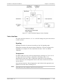
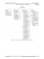
Figure 1-7. Vmux-210 Block Diagram: 3-Way Routing – Routing Between Network
Port, User Port, and E1/T1/Serial Uplink
Figure 1-8. Vmux-210 Block Diagram: Routing Between the E1/T1/Serial Port and
the Ethernet Switch
1-8
Functional Description
Vmux-210 Ver. 1.1
Installation and Operation Manual
Chapter 1 Introduction
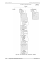
Figure 1-9. Vmux-210 Block Diagram: Router Disabled
Voice Interface
The voice interface includes 12, 15, 24, or 30 FXS analog voice ports that connect
to POTS or faxes.
Signaling
Signaling information is processed according to the CAS signaling mode.
Analog ports translate the physical signal to ABCD bits. The user configures this
translation, for example, the user may define the value “1101” to indicate
“ONHOOK”.
Compression
The DSPs handle the voice traffic by compressing it according to G.723.1 (6.4 or
5.3 kbps) and G.729 A (8 kbps), or digitizes it according to the G.711
requirements (A-law and μ-law). Compression methods are user-selectable.
G.711 A-law and μ-law configuration must be the same on both the local and
remote devices.
Voice Activity Detection, Silence Suppression, and Comfort Noise generation are
applied for all coder rates, including G.711.
Note
Vmux-210 Ver. 1.1
All bundles must be configured with the same coder rate.
Functional Description
1-9
Chapter 1 Introduction
Installation and Operation Manual
Voice Activity Detection
Voice Activity Detection (VAD) uses digital signal processing techniques to
distinguish between silence and speech on a voice connection. VAD reduces the
bandwidth requirements of a voice connection by generating traffic only during
periods of active voice conversation. With Comfort Noise Generation (CNG)
supported at the remote site, VAD significantly reduces bandwidth consumption
without degrading voice quality. VAD achieves additional bandwidth savings when
combined with voice compression techniques.
TDMoIP Multiplexing
Compressed voice payload is multiplexed by using the TDMoIP technique. The
multiplexing is performed by the Vmux-210 software. The DSPs send a continuous
stream of voice packets; which are multiplexed into a TDMoIP frame by adding
AAL2 headers and a TDMoIP header. Figure 1-10 illustrates the TDMoIP frame
structure.
TDMoIP AAL2
Header Header
Voice
Packet
AAL2
Header
Voice
Packet
Figure 1-10. TDMoIP Frame Structure
The size of the TDMoIP frame is determined by the following parameters:
•
•
Packetizing interval – The maximum time interval allocated for the TDMoIP
frame aggregation (10 to 90 mSec).
Maximum bytes per multiplexed frame – The maximum size of each frame
(100 to 1461 bytes).
The Vmux-210 continues filling the TDMoIP frame until one of the conditions
defined by the above parameters is met.
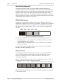
Ethernet Frame
At a later stage, the TDMoIP frame becomes a part of the standard Ethernet
frame, which also includes a UDP header, IP header and MAC. The Ethernet
frames are forwarded to the CPU, which sends them to the Ethernet or
E1/T1/Serial main links.
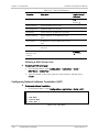
Figure 1-11 illustrates the structure of the Vmux-210 Ethernet frame. Table 1-1
describes the fields of the Vmux-210 Ethernet frame.
Ethernet
IP
UDP
TDMoIP AAL2 Voice AAL2 Voice AAL2 Voice Ethernet
Figure 1-11. Ethernet Frame Structure
When AAL2oMPLS multiplexing is used, the IP and UDP headers are not included
in the Ethernet frame.
1-10
Functional Description
Vmux-210 Ver. 1.1
Installation and Operation Manual
Note
Chapter 1 Introduction
When using the E1/T1/Serial main link, an additional 4 bytes are added to the
packet (HDLC framing).
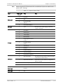
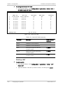
Table 1-1. Ethernet Frame Fields
Layer
MAC Layer
LLC Layer
IP Layer
UDP Layer
Data Layer
MAC Layer
Vmux-210 Ver. 1.1
Field Length
[bytes]
Field
Note
7
Preamble
1
SFD
6
Destination MAC
Address
6
Source MAC Address
2
Type
1
Vers/HLEN
1
Service Type
2
Total Length
2
Identification
1
Flags/Fragment Offset
(most)
1
Fragment Offset
(least)
1
Time to Live
1
Protocol
2
Header Checksum
4
Source IP Address
4
Destination IP Address
2
UDP Source Port
The UDP source port field is used to transfer
a destination bundle number.
2
UDP Destination Port
Fixed value of 2142 (decimal). Assigned to
RAD by the IANA
2
UDP Message Length
2
UDP Checksum
...
Payload
4
CRC
IEEE 802.1D&Q VLAN Tagging (additional
4 bytes if enabled)
Functional Description
1-11
Chapter 1 Introduction
Installation and Operation Manual
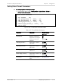
Table 1-2. Ethernet Frame Fields (AAL2oMPLS Multiplexing)
Layer
Field Length
[bytes]
Field
Note
7
Preamble
1
SFD
6
Destination MAC
Address
6
Source MAC Address
LLC Layer
2
Type
Data Layer
...
Payload
MAC Layer
4
CRC
MAC Layer
IEEE 802.1D&Q VLAN Tagging (additional
4 bytes if enabled)
VLAN Support (per bundle)
Vmux-210 supports VLAN, according to IEEE 802.1D&Q. When VLAN support is
enabled, Vmux-210 adds four bytes to the MAC layer of the Ethernet frame. The
content of these bytes, MAC layer priority and VLAN ID, can be set by the user. In
this mode, only VLAN format frames are sent and received by Vmux-210. The
following figure describes the VLAN tag format.
81
00
8
802.1D Tag Protocol Type
(802.1QTagType)
6
VID
CFI = 0
user_priority
5
4
Priority
1
8
1
VLAN ID
Figure 1-12. VLAN Tag Format
UDP Support
Table 1-3. UDP Source Port as Destination Voice Port
Field Length
Field Description
Value
2 bytes
UDP Source Port*
2 – 497d
2 bytes
UDP Destination Port
2142d
* – The MSB of this field can be either 1 or 0 for inband end-to-end proprietary
signaling.
Note
1-12
The UDP Source Port field is used for destination voice bundle indication.
Functional Description
Vmux-210 Ver. 1.1
Installation and Operation Manual
Chapter 1 Introduction
For more information about VLAN tagging, see IEEE Std 802.1D&Q.
E1/T1/Serial Main Link
The E1/T1/Serial main links receive Ethernet frames from the CPU and forward
them to the remote device over a TDM network or a leased line.
The E1/T1/Serial Links normally transmit the HDLC data transparently. However, a
special mode to support applications opposite certain Cisco-manufactured
equipment is provided. This mode uses a Cisco HDLC header format.
Ethernet Main Link (ETH NET Port)
The 10/100BaseT main link receives Ethernet frames from the CPU via the
Ethernet switch and forwards them to the remote device over the IP network.
The 10/100BaseT main link supports full duplex transmission with
autonegotiation and half duplex with the backpressure option.
Ethernet User LAN (ETH USER Port)
The 10/100BaseT user LAN port receives Ethernet frames from the user's LAN via
the internal Ethernet switch and forwards them to the remote device over the
main link. This port supports full duplex transmission with autonegotiation and
half duplex with the backpressure option.
Rate Limiting on Ethernet ports
To solve the problem of transferring voice as well as 10/100 Mbps Ethernet data
over a TDM/Serial uplink with small bandwidth (for example, 256 kbps), the
ingress data rate on either Ethernet ports can be limited to one of several values
between 128 kbps and 8 Mbps, plus fragmentation of the packets.
Integral Ethernet Switch
All traffic between the voice ports, the Ethernet ports and the Serial Link is
routed through the Vmux-210’s built-in Ethernet switch. This switch provides the
capability for VLAN tagging of the various traffic, as well as the capability for
discarding unrecognized traffic.
VLAN Tagging on Ethernet and E1/T1/Serial Ports
The VLAN tagging feature enables adding a VLAN tag to the traffic coming out of
a certain port, in order to identify its source, as well as offering the ability to
remove the VLAN tag from all traffic coming out of a certain port. In addition, a
“Double Tagging” mode is available to always add a tag to packets, even if one
already exists. The VLAN ID and priority level of the added tag are given according
to the port from which the packet entered (ingress) the integral Ethernet switch.
For untagged packets, or packets tagged with an unrecognized ID, two possible
security policies can be set per port: ON (broadcast all) or OFF (discard all).
Vmux-210 Ver. 1.1
Functional Description
1-13
Chapter 1 Introduction
Installation and Operation Manual
Each VLAN tag contains a Priority field. The Ethernet switch in the Vmux-110
decides the transmission priority of a packet based on this field.
A packet whose VLAN ID appears in the VLAN table will exit (egress) the switch
based on the policy in the VLAN table (see next section).
VLAN Table
Vmux-210 includes a VLAN table, which can contain up to 64 entries, in which
packet egress policies are defined for different VLAN ids. A policy for a certain
VLAN ID determines which ports will transmit packets tagged with this ID, how
the ports will transmit them (tagged/untagged), and which ports will discard
packets tagged with this ID.
DHCP Client Support
To facilitate integration of a new device into a DHCP IP network, if the DHCP
client is enabled, but no IP address has been manually configured, Vmux-210 will
automatically request one from the DHCP server upon booting. Once an address
has been assigned by the DHCP server, it will be saved in the database. In order
to request a new address, the current one must be deleted (0.0.0.0).
Calculating Approximate Bandwidth Utilization
The following formula is used to calculate the approximate bandwidth utilization:
{
[(Header size x packets per second ) + (# timeslots x size of
compressed G.732 packet x 1000/30 x actual transmission time (%
non-silence) )] x 8 bytes per bit
1000 bits per kilobit
Note
}
rate
+ converted
to kbps
A Vmux Bandwidth Calculator tool is included on the Technical Documentation CD.
Bandwidth Utilization when using TDMoIP
By using TDMoIP multiplexing and the voice activity detection, Vmux-210 supports
a higher number of voice channels over TDM than it is possible by utilizing
conventional compression methods alone. TDMoIP multiplexing and grouping the
timeslots of compressed voice together into bundles with a common IP address
reduces the actual bandwidth used per channel to as low as 4 kbps (up to 16:1),
when all channels are active. Better compression, up to 20:1, is achieved when
some of the voice channels are idle.
Note
1-14
The actual compression achieved at any time depends on the voice activity on the
network, the signaling system in use, and the number of modem/fax calls.
Functional Description
Vmux-210 Ver. 1.1
Installation and Operation Manual
Chapter 1 Introduction
The actual bandwidth utilization is determined by the following factors:
•
Header sizes:
Ethernet – 18 bytes
IP – 20 bytes
UDP – 8 bytes
TDMoIP – 4 bytes
VLAN (if exists) – 4 bytes.
•
Size of the voice packet:
G.723 – 31 bytes (AAL2 header [3 bytes] + voice header [4 bytes] +
compressed voice payload [24 bytes])
G.729 – 17 bytes (AAL2 header [3 bytes] + voice header [4 bytes] +
compressed voice payload [10 bytes])
G.711 – 47 bytes (AAL2 header [3 bytes] + voice header [4 bytes] +
compressed voice payload [40 bytes]).
•
Packet interval:
G.723.1 – 30 mSec
G.729 – 10 mSec
G.711 – 5 mSec.
•
Number of timeslots in a bundle
•
Silence percentage. Studies show that an average person speaks only 40% of
the time during a telephone conversation. 50% of the time is spent listening
to the other party, while the remaining 10% is spent quietly contemplating.
•
Connectivity packets – 64 bytes per minute.
Calculating Approximate Bandwidth Utilization (TDMoIP):
Let us calculate an approximate bandwidth for 30 timeslots in one bundle with
G.723.1 compression, 60 % of silence:
{
[(50 x 1000/40) + (30 x 31 x 1000/30 x 0.4)] x 8
1000
}
+ 0.00853 = 109.208 kbps
where:
Vmux-210 Ver. 1.1
•
50 – size of Ethernet, IP, UDP, TDMoIP headers
•
1000/40 – packet per seconds (pps) transmission rate, calculated according
to the packetizing interval chosen (40 mSec in this example)
•
30 – number of timeslots
•
31 – size of the compressed G.723 packet plus AAL2 header and voice
payload
•
0.4 – 60% of silence
•
8 – conversion from bytes to bits
Functional Description
1-15
Chapter 1 Introduction
Note
Installation and Operation Manual
•
1000 in the denominator – conversion from bits to kilobits
•
0.00853 – connectivity packets rate (64 bytes per minute) converted to kbps.
A Vmux Bandwidth Calculator tool is included on the Technical Documentation CD.
Bandwidth Utilization when using AAL2oMPLS
When using non-IP based Ethernet networks or the Serial uplink, the AAL2oMPLS
format can be used instead of the TDMoIP multiplexing format. The AAL2oMPLS
header is smaller than the TDMoIP header (23 rather than 50 bytes), saving about
5% in bandwidth when compared to TDMoIP multiplexing (depending on the
actual size of the multiplexed frames).
The actual bandwidth utilization is determined by the following factors:
•
Header sizes:
Ethernet – 18 bytes
AAL2oMPLS – 5 bytes
•
Size of the voice packet:
G.723 – 31 bytes (AAL2 header [3 bytes] + voice header [4 bytes] +
compressed voice payload [24 bytes])
G.729 – 17 bytes (AAL2 header [3 bytes] + voice header [4 bytes] +
compressed voice payload [10 bytes]).
•
Packet interval:
G.723.1 – 30 mSec
G.729 – 10 mSec.
•
Number of timeslots in a bundle
•
Silence percentage. Studies show that an average person speaks only 40% of
the time during a telephone conversation. 50% of the time is spent listening
to the other party, while the remaining 10% is spent quietly contemplating.
•
Connectivity packets – 64 bytes per minute.
Calculating Approximate Bandwidth Utilization (AAL2oMPLS):
The approximate bandwidth for 30 timeslots in one bundle with G.723.1 (6.4
kbps) compression, 60 % of silence is calculated as follows:
{
[(23 x 1000/40) + (30 x 31 x 1000/30 x 0.4)] x 8
1000
}
+ 0.00853 = 103.80853 kbps
where:
1-16
•
23 – size of Ethernet and AAL2oMPLS headers
•
1000/40 – packets per second (pps) transmission rate, calculated according
to the packetizing interval chosen (40 mSec in this example)
•
30 – number of timeslots
Functional Description
Vmux-210 Ver. 1.1
Installation and Operation Manual
Note
•
31 – size of the compressed G.732 packet plus AAL2 header and voice
payload
•
0.4 – 60% of silence
•
8 – conversion from bytes to bits
•
1000 in the denominator – conversion from bits to kilobits
•
0.00853 – connectivity packets rate (64 bytes per minute) converted to kbps.
A Vmux Bandwidth Calculator tool is included on the Technical Documentation CD.
1.4
Ethernet Links
Chapter 1 Introduction
Technical Specifications
Number of Ports
2 (NET and USER)
Standards
IEEE 802.3, 802.3u, Ethernet 802.1D&Q
Data Rate
10 or 100 Mbps, half duplex or full duplex, autonegotiation
support
Statistics
According to RFC 3638 or RFC 3635:
• Received frames – Total Frames, good Frames,
Broadcast Frames, Multicast Frames, Undersize,
Oversize, CRC, Fragments, Jabber, Filtered, Discarded,
Total Bytes, Bytes
• Transmitted frames – Correct Frames, Broadcast
Frames, Multicast Frames, Collision, Bytes
Serial Link
Range
Up to 100m (328 ft) over UTP Cat.5 cable
Connectors
RJ-45 per port
Function
Main Link
Interface
• RS-530
• V.35 (requires adapter cable)
• X.21 (requires adapter cable)
Data Rate
n x 64 kbps, for rates from 64 to 2048 kbps
Timing
• DCE
• DTE (requires adapter/cross cable)
Connector
Vmux-210 Ver. 1.1
DB-25, female
Technical Specifications
1-17
Chapter 1 Introduction
Voice Ports
Configuration
Installation and Operation Manual
Choice of one of the following:
• 12, 15, or 24 FXS analog voice ports using a Telco-50
proprietary connector
• 30 FXS analog voice ports using a Telco-64 proprietary
connector
Router
Features
• Maximum of three interfaces
• Maximum 4000 pps
• Static routing
• DHCP server
• DHCP relay
• NAT
• Firewall
E1 Link
Number of Ports
One
Data Rate
2.048 Mbps
Standards
ITU-T Rec. G.703, G.704, G.706, G.732, G.823
Framing
G.732N with or without CRC-4, in compliance with ITU-T
Rec. G.703, G.704, G.732 requirements
Line Code
HDB3
Receive Signal
Level
0 to -43 dB with LTU
Transmit Signal
Level
±3V (±10%)
Jitter
Performance
Per ITU-T G.823
Line Impedance
120Ω, balanced
Connector
RJ-45, balanced
0 to -12 dB without LTU
CBL-RJ45/2BNC/E1 adapter cable converts to a pair of BNC
coaxial connectors, unbalanced
T1 Link
1-18
Number of Ports
One
Data Rate
1.544 Mbps
Standards
ANSI T1.403, ITU-T Rec. G.703
Line Code
AMI
Technical Specifications
Vmux-210 Ver. 1.1
Installation and Operation Manual
Zero
Suppression
B8ZS, AMI
Framing
D4, ESF
Receive Signal
Level
0 to -36 dB with CSU
Transmit Signal
Level
FXS Ports
Chapter 1 Introduction
0 to -13 dB without CSU
0, -7.5, -15, or -22.5 dB with CSU
±2.7V (±10%) at 0–655 ft without CSU
Jitter
Performance
Per AT&T TR-62411, G.824
Line Impedance
100Ω, balanced
Connector
RJ-45
Number of Ports
12, 15, 24, or 30
Analog
Parameters
ITU-T standards: G.713, 2-wire for voice and signaling
Nominal level: 0 dBm
Nominal impedance: 600Ω
Return loss (300 to 3400 Hz): better than 20 dB
Frequency response (Ref: 1020 Hz):
• 300 to 3000 Hz: ±0.5 dB
• 250 to 3400 Hz: ±1.1 dB
Level Adjustment, soft selectable:
• TX: +5 dBm to -4 dBm
• RX: +5 dBm to -10 dBm
• Steps: 1 dB (±0.1 dB), nominal
Signal to Total Distortion, G.712, G.713 method 2:
• 0 to -30 dBm0: better than 33dB
• +3 to -45 dBm0: better than 22dB
Idle channel noise: better than -70 dBm0 (+20 dBrnc)
Connectors
Telco-50 or Telco-64 connector
Signaling
Signaling type: EIA RS-464 Loop-Start
On-Hook/Off-Hook Threshold:
• 3V to 38V between TIP and RING at off-hook state
• Higher than 40V between TIP and RING at on-hook
state
Vmux-210 Ver. 1.1
Technical Specifications
1-19
Chapter 1 Introduction
Installation and Operation Manual
Feed Current: 24 mA ±10%
Ringer:
• Voltage: 50 VRMS (±10%), overload protected
• Frequency: 25 Hz (±10%)
• Cadence: 1 sec ON / 3 sec OFF (default),
user-configurable
Reverse Polarity Generation
Pulse Metering Generation: 16 KHz or 12 KHz (user
selectable)
Voice
Processing
Control Port
Diagnostics
Compression
Algorithms
G.723.1, G.729 A, G.711 (a-law/μ-law)
Silence
Suppression
G.723.1A, G.729B
Echo
Cancellation
32 ms per channel as per G.168
Modem Relay
All common rates and standards
Fax Relay
Group III: 4.8, 9.6, 14.4 kbps
Voice-Band
Modem
Transparent transfer
MF Signaling
Support
DTMF detection, generation and relay
Caller ID Relay
Conforms to U.S. standard (Telcordia Bellcore type 1), as
well as to European standard (V.23), user-selectable.
Available only with G.729A (8 kbps) codec.
Standard
V.24/RS-232 (DCE)
Data Rate
9.6, 19.2, 38.4, 57.6 or 115.2 kbps
Connector
DB-9
Tests
Ethernet Ports:
• Performance monitoring
• LAN statistics
• PING
FXS Voice Ports:
• Remote loops per channel
• Tone injection per channel towards local and remote
side
1-20
Technical Specifications
Vmux-210 Ver. 1.1
Installation and Operation Manual
Statistics
Collection
Chapter 1 Introduction
• Ethernet
• CPU utilization
• HDLC
• Bundles
• Voice
• Voice Rx and Tx signaling
Indicators
Power Supply
PWR (green)
Power
TST (green)
Test status
ALM (red)
Alarm status
Input
AC Source: 100 to 240 VAC, 50/60 Hz
DC Source: -40 to -72 VDC (-48 VDC, nominal)
Consumption
12FXS:
• AC: 40.0 W
• DC: 44.0 W
15FXS:
• AC: 41.6 W
• DC: 45.6 W
24FXS:
• AC: 56.0 W
• DC: 61.0 W
30FXS:
• AC: 63.0 W
• DC: 69.0 W
Physical
Environment
Vmux-210 Ver. 1.1
Height
4.3 cm/1.7 in
Width
44.0 cm/17.3 in
Depth
24.0 cm/9.5 in
Weight
3.5 kg /7.7 lb
Operating
Temperature
0 to 50°C/32 to 122°F
Storage
Temperature
-20 to 70°C/-4 to 158°F
Humidity
Up to 90%, non-condensing
Technical Specifications
1-21
Chapter 1 Introduction
1-22
Technical Specifications
Installation and Operation Manual
Vmux-210 Ver. 1.1
Chapter 2
Installation and Setup
2.1
Introduction
The Vmux-210 unit is designed for desktop or bench installation and is delivered
as a fully assembled unit. No provisions are made for bolting the unit to a
tabletop. For installation of one or two units in a 19” rack, refer to the Rack
Mounting Kit for 19-inch Racks Guide that comes with the rack mounting kit.
The following is a summary of the installation steps. These steps are described in
more detail later in this chapter.
To install Vmux-210:
1. Prepare the installation site in accordance with your application. See Site
Requirements and Prerequisites on page 2-2.
2. Review the package contents, and verify that all items are present. See
Package Contents on page 2-2.
3. Connect the cables:
Connect the main link to the 10/100BaseT (NET Ethernet) port or the
E1/T1/Serial port.
Connect the LAN to the USER Ethernet port.
Connect an ASCII terminal or a PC running a terminal emulation software.
Connect power to the unit.
After installing the unit:
•
See Chapter 3 for the operating instructions.
•
See Chapter 4 for the detailed system configuration procedures using an
ASCII terminal connected to the Vmux-210 control port.
•
If a problem is encountered, see Chapter 6 and Chapter 7 for testing and
diagnostic instructions.
Internal settings, adjustment, maintenance, and repairs may be performed only
by a skilled technician who is aware of the hazards involved.
Warning
Vmux-210 Ver. 1.1
Always observe standard safety precautions during installation, operation, and
maintenance of this product.
Introduction
2-1
Chapter 2 Installation and Setup
2.2
Installation and Operation Manual
Site Requirements and Prerequisites
The AC-powered Vmux-210 unit should be installed within 1.5 m (5 ft) of an
easily accessible, grounded AC outlet capable of furnishing the voltage in
accordance with Vmux-210 nominal supply voltage.
The DC-powered Vmux-210 unit requires a -48 VDC power source, which must be
adequately isolated from the main supply.
Allow at least 90 cm (36 in) of frontal clearance for operating and maintenance
accessibility. Allow at least 10 cm (4 in) clearance at the rear of the unit for signal
lines and interface cables.
The ambient operating temperature of Vmux-210 is 0 to 50°C (32 to 122°F), at a
relative humidity of up to 90%, non-condensing.
2.3
Package Contents
The Vmux-210 package includes the following items:
•
One Vmux-210 unit
•
Technical Documentation CD
•
AC power cord or DC power supply connector kit
•
RM-34 kit.
2.4
Equipment Needed
Vmux-210 standalone unit is designed for desktop or bench installation and is
delivered fully assembled. No provisions are made for bolting the unit to a
tabletop.
Mounting Vmux-210 in a 19-inch rack, however, requires a 3 mm Phillips
screwdriver and an RM-34 kit. For the rack installation instructions, refer to the
Rack Mounting Kit for 19-inch Racks guide that comes with the RM kit.
Power Cable
AC-powered Vmux-210 is equipped with an appropriate power cord (country or
region dependent) to be connected from the mains to the power socket of the
power unit (accessible from the front panel).
DC-powered Vmux-210 is equipped with an appropriate DC connector kit, which
should be used for preparing the DC cable connection.
2-2
Equipment Needed
Vmux-210 Ver. 1.1
Installation and Operation Manual
Chapter 2 Installation and Setup
Table 2-1. Required Interface Cables
Interface
Cable Type
Terminal Control
DB-9 to DB-9, RS-232/V.24 compliant cable for
ASCII-based terminal control
Ethernet
Cat. 5, RJ-45 to RJ-45, IEEE 802.3 compliant cable
Balanced E1
RJ-45 to RJ-45 E1 compliant cable
Unbalanced E1 interface
Adapter cable, CBL-RJ45/2BNC/E1, which has one RJ-45
plug for connection to the Vmux-420 E1 connector and
two BNC female connectors at the other end.
FXS (12, 15, 24 channel
versions)
Telco-50 cable
FXS (30 channel versions)
Telco-64 cable
2.5
Mounting the Unit
Vmux-210 is designed for installation on a desktop, or in a 19" rack.
•
For rack mounting instructions, refer to the RM-34 Installation Kit Manual.
•
If Vmux-210 is to be used as a desktop unit, place and secure the unit on a
stable, non-movable surface.
Refer to the clearance and temperature requirements in Site Requirements and
Prerequisites.
2.6
Connecting to the FXS Voice Port
The FXS voice interface terminates in a Telco-50 or Telco-64 proprietary
connector. Appendix A specifies the pinout of the FXS connectors.
ETH
Vmux-210
USER
CHANNELS 1-30
NET
E1/T1
SERIAL LINK
CONTROL
PWR
TST
ALM
LINK
ACT
LINK
ACT
Figure 2-1. FXS Connector
To connect the FXS voice interface:
•
Vmux-210 Ver. 1.1
Connect FXS voice interface to the connector on the Vmux-210 rear panel
labeled Channels 1-x.
Connecting to the FXS Voice Port
2-3
Chapter 2 Installation and Setup
2.7
Installation and Operation Manual
Connecting to the Main Link
The Vmux-210 main link may be either the Ethernet NET interface or the
E1/T1/Serial main link interface.
Connecting to the Ethernet Main Link
The Vmux-210 Ethernet NET main link interface terminates in an 8-pin RJ-45
connector. Appendix A specifies the pinout of the Ethernet connector. The
Ethernet main link port supports connection via straight and cross cables.
ETH
Vmux-210
USER
CHANNELS 1-30
NET
E1/T1
SERIAL LINK
CONTROL
PWR
TST
ALM
LINK
ACT
LINK
ACT
Figure 2-2. ETH NET Connector
To connect to the Ethernet main link:
•
Connect the IP uplink to the RJ-45 connector designated ETH NET.
Connecting to the Serial Main Link
The serial main link interface terminates in a female DB-25 connector. Appendix A
specifies the pinout of the serial connector.
ETH
Vmux-210
USER
CHANNELS 1-30
NET
E1/T1
SERIAL LINK
CONTROL
PWR
TST
ALM
LINK
ACT
LINK
ACT
Figure 2-3. SERIAL LINK Connector
To connect the Serial main link:
•
Connect the serial V.35 link to the DB-25 connector designated SERIAL.
Connecting to the E1 Link
The E1 link terminates in an RJ-45 balanced connector. Appendix A specifies the
pinout of the E1 connector.
ETH
Vmux-210
USER
CHANNELS 1-30
NET
E1/T1
SERIAL LINK
CONTROL
PWR
TST
ALM
LINK
ACT
LINK
ACT
Figure 2-4. E1 Connector
2-4
Connecting to the Main Link
Vmux-210 Ver. 1.1
Installation and Operation Manual
Chapter 2 Installation and Setup
To connect the balanced E1 interface:
•
Connect the incoming E1 link to the RJ-45 connector on the Vmux-210 rear
panel, designated E1.
To connect the unbalanced E1 interface:
1. Connect the receive line to the connector labeled RX of the
CBL-RJ45/2BNC/E1 adapter cable, using a 75Ω coaxial cable.
2. Connect the transmit line to the connector labeled TX of the
CBL-RJ45/2BNC/E1 adapter cable, using a 75Ω coaxial cable.
3. Connect the CBL-RJ45/2BNC/E1 adapter cable to the RJ-45 connector on the
Vmux-210 rear panel, designated E1.
Connecting to the T1 Link
The T1 link terminates in an RJ-45 balanced connector. Appendix A specifies the
pinout of the T1 connector.
ETH
Vmux-210
USER
CHANNELS 1-30
NET
E1/T1
SERIAL LINK
CONTROL
PWR
TST
ALM
LINK
ACT
LINK
ACT
Figure 2-5. T1 Connector
To connect the T1 interface:
•
Connect the T1 link to the RJ-45 connector on the Vmux-210 rear panel,
designated T1.
2.8
Connecting to the User LAN Port
The user LAN can be connected to the Ethernet USER port. Appendix A specifies
the pinout of the Ethernet connectors.
ETH
Vmux-210
USER
CHANNELS 1-30
NET
E1/T1
SERIAL LINK
CONTROL
PWR
TST
ALM
LINK
ACT
LINK
ACT
Figure 2-6. USER ETH Connector
To connect the user LAN port:
•
Vmux-210 Ver. 1.1
Connect the user LAN to the RJ-45 connector designated ETH USER.
Connecting to the User LAN Port
2-5
Chapter 2 Installation and Setup
2.9
Installation and Operation Manual
Connecting to the ASCII Terminal
The Vmux-210 control port terminates in a DB-9 connector. Appendix A specifies
the pinout of the control port connector.
ETH
Vmux-210
USER
CHANNELS 1-30
NET
E1/T1
SERIAL LINK
CONTROL
PWR
TST
ALM
LINK
ACT
LINK
ACT
Figure 2-7. CONTROL Connector
To connect to an ASCII terminal:
•
Connect the DB-9 connector (designated CONTROL) to the ASCII terminal, or
PC running a terminal emulation software.
2.10 Connecting to Power
Vmux-210 includes AC or DC power supply. To connect Vmux-210 to the power
source, see the appropriate section below, depending on your version of the unit
(AC or DC).
Warning
Before switching on this unit and connecting or disconnecting any other cable,
the protective earth terminals of this unit must be connected to the protective
ground conductor of the mains (AC or DC) power cord. If you are using an
extension cord (power cable) make sure it is grounded as well.
Any interruption of the protective (grounding) conductor (inside or outside the
instrument) or disconnecting of the protective earth terminal can make this unit
dangerous. Intentional interruption is prohibited.
Connecting to AC Power
AC power is supplied to Vmux-210 through a standard 3-prong plug.
AC power should be supplied through the 1.5 m (5 ft) standard power cable
terminated by a standard 3-prong plug. The cable is provided with the unit.
To connect Vmux-210 to AC power:
1. Connect the power cable to the power connector on the Vmux-210 rear
panel.
2. Connect the power cable to the electricity outlet.
The unit will turn on automatically upon connection to the electricity
supply.
2-6
Connecting to Power
Vmux-210 Ver. 1.1
Installation and Operation Manual
Chapter 2 Installation and Setup
Connecting to DC Power
DC power is supplied to Vmux-210 through a special 3-prong plug.
To connect Vmux-210 to DC power:
•
Vmux-210 Ver. 1.1
Refer to the DC power supply connection supplement, located on the
Technical Documentation CD or at the back of the official printed version of
this manual. Also, refer to the safety instructions at the beginning of this
document.
Connecting to Power
2-7
Chapter 2 Installation and Setup
2-8
Connecting to Power
Installation and Operation Manual
Vmux-210 Ver. 1.1
Chapter 3
Operation
This chapter provides the following information for Vmux-210:
•
Vmux-210 front-panel indicators
•
Operating procedures (turn-on, front-panel indications, performance
monitoring and turn-off).
The installation procedures given in Chapter 2 must be completed and checked
before attempting to operate the Vmux-210.
3.1
Turning On the Unit
To turn on the unit:
•
Connect the power cable to the electricity outlet.
The PWR indicator lights up and remains lit as long as Vmux-210 receives
power.
Table 3-1 shows the correct status of the indicators a few seconds after
power-up.
Table 3-1. Vmux-210 Indicator Status
Indicator
Status
PWR
ON
TST
OFF
ALM
OFF
If the above LED indications do not appear following initial power turn-on, see
Chapter 6 for the diagnostic test instructions.
Vmux-210 Ver. 1.1
Turning On the Unit
3-1
Chapter 3 Operation
3.2
Installation and Operation Manual
Indicators
The Vmux-210 front panel includes a series of LED indicators that show the
current operating status of the unit (see Figure 3-1).
Vmux-210
PWR TST ALM
Figure 3-1. Vmux-210, Front Panel
Table 3-2 lists and describes Vmux-210 indicators.
Table 3-2. Vmux-210 LEDs
3.3
Name
Function
PWR (green)
ON – Power supply is ON
TST (yellow)
ON – Test is in progress
ALM (red)
ON – Alarm is present
Default Settings
Vmux-210 is managed by an ASCII terminal or PC running a terminal emulation
program via menu-driven embedded software. The following tables list the
default settings of the Vmux-210 configuration parameters.
Table 3-3. System Default Settings
Parameter
Default Value
Configuration > System
Main Link
Ethernet
Router
Disable
Ethernet Net/User Connection
Layer 2 Switching
Configuration > System > Management
3-2
Host Mux Name
None
Telnet/Web Access
Enable
Auto Logout Time
3 minutes
Default Settings
Vmux-210 Ver. 1.1
Installation and Operation Manual
Chapter 3 Operation
Table 3-3. System Default Settings (Cont.)
Parameter
Default Value
Configuration > System > Management > Host IP
IP address
0.0.0.0
Subnet Mask
0.0.0.0
Default Gateway
0.0.0.0
DHCP Client
Disable
Read
public
Write
private
Trap
public
Configuration > System > Management > Manager List
Manager list
No managers defined
Configuration > System > Alarm Operations
Alarm LED Severity
Event
Table 3-3. Physical Port Default Settings
Parameter
Default Value
Configuration > Physical Ports > Ethernet
Port
Network
Auto Negotiation
Enable
Ingress Rate Limit
No Limit
Configuration > Physical Ports > Serial Uplink
Vmux-210 Ver. 1.1
Interface Type
V35
Connect
No
Speed (N*64)
1
Clock Mode
DTE
Control Signals
Ignore
Fragmentation
610
HDLC Mode
Transparent HDLC
Loop Detect
Disable
Default Settings
3-3
Chapter 3 Operation
Installation and Operation Manual
Table 3-3. Physical Port Default Settings (Cont.)
Parameter
Default Value
Configuration > Physical Ports > E1/T1 Uplink > T1 Parameters
Connect
No
Frame Type
ESF
Clock Mode
LBT
Interface Type
CSU
Restoration Time
1 Second (Fast)
Idle Code
FF
Line Code
B8ZS
Rx Sensitivity
LOW (-15 dB)
Tx Gain Level
0 dB
Line Length
0-133
Fragmentation
610
HDLC Mode
Transparent HDLC
Loop Detect
Disable
Configuration > Physical Ports > E1/T1 Uplink > E1 Parameters
Connect
No
Frame Type
G732N
Clock Mode
LBT
Interface Type
DSU
Restoration Time
1 Second (Fast)
Idle Code
FF
Line Termination
Balanced
Fragmentation
610
HDLC Mode
Transparent HDLC
Loop Detect
Disable
Configuration > Physical Ports > E1/T1 Uplink > Time Slot Table
Timeslots
No timeslots connected
Configuration > Physical Ports > Analog > Timeouts
3-4
Ring Timeout (sec)
120
On Hook Duration in Flash (msec)
700
Default Settings
Vmux-210 Ver. 1.1
Installation and Operation Manual
Chapter 3 Operation
Table 3-3. Physical Port Default Settings (Cont.)
Parameter
Default Value
Configuration > Physical Ports > Analog > Ringer Profiles
Period #1: Ring (x 100 msec)
10
Period #1: Silence (x 100 msec)
30
Period #2: Ring (x 100 msec)
0
Period #2: Silence (x 100 msec)
0
Configuration > Physical Ports > Analog > Gains
Tx Gain (dB)
0
Rx Gain (dB)
-4
Configuration > Bundles > Configure
Bundles
No bundles defined
Configuration > Bundles > Configure > Edit Bundle > Routing Parameters
Destination IP
0.0.0.0
Destination Bundle
1
TOS Byte
0x00
Configuration > Bundles > Configure > Edit Bundle > Routing Parameters > VLAN
Parameters
VLAN Tagging
No
Configuration > Bundles > Configure > Edit Bundle > Connectivity Parameters
Connectivity Mode
With Ping
Connectivity Packet Rate (sec)
60
Connectivity Timeout Cycles
3
Configuration > Bundles > Configure > Edit Bundle > Voice Parameters
Coder/Rate
G.723.1/6.4
Noise Level for VAD
Low
Echo Canceller
Enable
Caller ID Tx Delay (mSec)
400
Configuration > Bundles > Configure > Edit Bundle > Voice Parameters >
Fax/Modem
Modem
Modem Relay
Fax
Enable
Fax Rate (kbps)
14.4
Configuration > Bundles > Configure > Edit Bundle > Signaling Parameters
Vmux-210 Ver. 1.1
Ringback
Enable
Reverse Polarity
Disable
Pulse Metering
Disable
Default Settings
3-5
Chapter 3 Operation
Installation and Operation Manual
Table 3-3. Physical Port Default Settings (Cont.)
Parameter
Default Value
Configuration > Bundles > Configure > Edit Bundle > Signaling Parameters >
Signaling Bits
Signaling Bits
A Bit B Bit C Bit D Bit
On Hook
0
1
0
1
Off Hook
1
1
0
1
Ring I
1
1
0
1
Ring II
1
1
0
1
Reverse Polarity 1
0
0
1
Pulse Metering
0
0
1
1
Configuration > Bundles > Channel Distribution > Configure
Port Distribution
All ports are not connected
Table 3-3. Bridge Default Settings
Parameter
Default Value
Configuration > Applications> Bridge > Bridge Port
Bridge Port
Network
Ingress Filtering
Disable
Port VID
1
Default Priority Tag
0
Egress Tag Handling
None
Ingress Tag Handling
None
Configuration > Applications> Bridge > VLAN Membership
VLAN Table
No VLAN entries
Table 3-3. Router Default Settings
Parameter
Default Value
Configuration > Applications > Router > Interfaces > Uplink Port Configuration
3-6
IP
0.0.0.0
Mask
0.0.0.0
ARP Table Aging Time (minutes)
5
DHCP Relay
Disable
Relay to DHCP Server IP
0.0.0.0
Default Settings
Vmux-210 Ver. 1.1
Installation and Operation Manual
Chapter 3 Operation
Table 3-3. Router Default Settings (Cont.)
Parameter
Default Value
Configuration > Applications > Router > Interfaces > Network Port Configuration
IP
0.0.0.0
Mask
0.0.0.0
DHCP Client
Disable
ARP Table Aging Time (minutes)
5
DHCP Relay
Disable
Relay to DHCP Server IP
0.0.0.0
Configuration > Applications > Router > Interfaces > User Port Configuration
IP
0.0.0.0
Mask
0.0.0.0
ARP Table Aging Time (minutes)
5
DHCP Relay
Disable
Relay to DHCP Server IP
0.0.0.0
Configuration > Applications > Router > Interfaces >
Uplink/Network/User Port Configuration > RIP
RIP Status
Disable
Send RIP type
None
Receive RIP type
None
Configuration > Applications > Router > Interfaces >
Uplink/Network/User Port Configuration > Firewall
Firewall Status
Disable
Firewall Direction
Outbound
Active FTP
No
Forged IP Protection
No
Configuration > Applications > Router > Default Gateway
Default Gateway
Disable
Default Gateway IP
0.0.0.0
Configuration > Applications > Router > DHCP Server
DHCP Server
Disable
Configuration > Applications > Router > NAT
NAT
Vmux-210 Ver. 1.1
No address translations defined
Default Settings
3-7
Chapter 3 Operation
Installation and Operation Manual
Table 3-3. Router Default Settings (Cont.)
Parameter
Default Value
Configuration > Applications > Router > Firewall Global Parameters
All Fragments
No
TCP Aging (seconds)
15
UDP Aging (seconds)
15
ICMP Aging (seconds)
15
Default Aging (seconds)
15
Configuration > Applications > Router > Firewall Global Parameters > Define Rules
Firewall Rules
3.4
No rules defined
Configuration and Management Alternatives
Vmux-210 has several management options:
•
ASCII Terminal – connected to Vmux-210 via the RS-232 control port
•
Telnet – access to the configuration screens via any Telnet application
•
ConfiguRAD – access to the configuration screens via Web browser
•
RADview – RAD’s user-friendly SNMP-based GUI application, or by other
SNMP-based management applications.
Working with an ASCII Terminal
Vmux-210 configuration and monitoring operations can be performed locally,
using an ASCII terminal connected to the control port, or remotely via Telnet or a
Web browser. The following functions are available:
•
Viewing system information
•
Modifying configuration and operation settings
•
Viewing statistics and status
•
Performing diagnostics.
Vmux-210 configuration can also be performed remotely using an SNMP
application (for example, RADview).
Initiating a Control Session
Any standard ASCII terminal (a “dumb” terminal or a personal computer running a
terminal emulation application) equipped with a V.24/RS-232 communication
interface can be used to configure Vmux-210.
Vmux-210 automatically adjusts to the terminal rate, for any rate between
9.6-115.2 kbps.
3-8
Configuration and Management Alternatives
Vmux-210 Ver. 1.1
Installation and Operation Manual
Chapter 3 Operation
To initiate a control session:
1. Connect the terminal cable to the CONTROL connector on the Vmux-210 back
panel.
2. Connect the terminal cable to the serial port of the control terminal.
3. Turn the control terminal on.
4. Configure the terminal to the default communication parameters: one start
bit, eight data bits, no parity, one stop bit, no flow control, VT100 emulation.
5. Turn Vmux-210 on.
6. After Vmux-210 completes the boot sequence (approximately 50 seconds),
press <Enter> several times.
The rate is detected automatically.
Logging In
You have to enter a user name and password in order to start the Vmux-210
management software (see Figure 3-2).
USER NAME:
PASSWORD:
ESC - clear; & - exit
Figure 3-2. Password Request Screen
To enter the user name and password:
1. Type your user name, and press <Enter>.
2. Type your password (up to eight characters), and press <Enter>.
The Main Menu appears (see Figure 3-3).
Main Menu
1. Inventory[]
2. Configuration>
3. Monitoring>
4. Diagnostics>
5. File Utilities>
>
Please choose item <1 to 5>
@ - Db Update; # - Db Undo
ESC-prev.menu; !-main menu; &-exit
Figure 3-3. Main Menu
Vmux-210 Ver. 1.1
Configuration and Management Alternatives
3-9
Chapter 3 Operation
Installation and Operation Manual
Navigating the Management Menus
This section provides a general description of the software menu operation and
conventions for navigating the menus. Menu Map on page 3-15 lists all menus of
the Vmux-210 management software.
Selecting Parameters
To select an option:
•
Type the number corresponding to the option, and press <Enter>.
The screen for the chosen option appears.
To correct an erroneous entry:
•
Press <Backspace> to clear the error, and then enter the correct characters.
Alternatively, press <Esc> to exit the current menu, and then return to the
menu to re-enter the required value.
Saving and Aborting Configuration Changes
You must save the configuration changes by updating the Vmux-210 database. If
the database is not updated, Vmux-210 discards all the user settings when it is
reset. You can save changed values at any stage of the configuration procedure.
Alternatively, you can abort the new settings and return to the previous values.
To save the changes:
1. Type @ (Shift+2) and press <Enter>.
Vmux-210 displays the following confirmation message:
Are you sure you want to update data base?
Press Y/N :
2. Type Y to save the changes.
Vmux-210 displays the following message:
Data base was changed. Press any key to continue.
3. Press any key to continue the management session.
Note
Each time you update the Vmux-210 database, the management software
analyzes the changes. If a major error is detected, Vmux-210 aborts the database
update and displays the following message, followed by the list of detected
configuration errors:
Data base update failed. Sanity Error Occurred.
To undo the changes:
1. Type # (Shift+3) and press <Enter>.
Vmux-210 displays the following confirmation message:
Are you sure you want to undo data base?
Press Y/N :
2. Type Y to abort the changes and use the previous database settings.
3-10
Configuration and Management Alternatives
Vmux-210 Ver. 1.1
Installation and Operation Manual
Chapter 3 Operation
Using Terminal Hot Keys
Terminal hot keys are provided per screen to enhance the functionality that is
required of that screen. The available hot keys are listed in the lower part of each
screen. The following hot keys are system keys, available on screens:
•
Esc – Return to previous menu
•
! – Return to the Main Menu
•
& – Exit to password screen (to prevent unauthorized access after completing
the session)
•
@ – Update database
•
# – Undo database (only changes since last update)
•
Ctrl+D – Scroll down (read-only tables)
•
Ctrl+U – Scroll up (read-only tables)
•
Arrow Keys, Tab – Scroll (read-write tables)
•
G <row number>,<column number> – Go to cell (read-write tables)
•
? – Help screen
The path at the top of the screen indicates the menu path for reaching the
currently displayed menu from the Main Menu (for example:
Main>Configuration>System).
Sample Help Screen
The following figure shows a typical Help screen, which summarizes the keyboard
shortcuts that are available in the functional screen from which the Help screen
was invoked.
The Help screen is invoked by pressing SHIFT-/ (the ‘?’ symbol) from the relevant
functional screen. However, not all functional screens have Help available.
Table Hot Keys
Right Arrow – move right
Down Arrow – move down
TAB - select next changeable cell
G <row number>,<col number> - go to cell
Figure 3-4. Typical Help Screen
Security Levels
Vmux-210 supports a four-level security and user authentication system:
Vmux-210 Ver. 1.1
•
Administrator – Allowed to configure all the parameters of Vmux-210.
•
Operator – Allowed to perform all operations in the system, except for user
administration (adding/deleting users, changing user definitions).
•
Technician – Allowed to test Vmux-210 and monitor its operation (for
example, monitoring alarms.
Configuration and Management Alternatives
3-11
Chapter 3 Operation
•
Installation and Operation Manual
Monitor – Allowed to monitor the Vmux-210 operation.
The maximum number of users supported by Vmux-210 is 20. When managing
Vmux-210 over Telnet, up to five simultaneous management sessions are
permitted. Only one administrator or operator is allowed to enter the
management session at a time. The other four users may enter the session as
monitors.
Vmux-210 displays the management menus in accordance with a user’s access
rights. For example, configuration screens dealing with the unit configurations are
not available to users who logged in as technicians or monitors.
Default Security Configuration
Vmux-210 is supplied with two administrator accounts:
•
Account 1:
User name: admin
Password: 12345.
•
Account 2:
User name: su
Password: 1234.
When the first management session is initiated, it is recommended to create a
new administrator account, and delete the default one.
Note
If the password is lost, consult your local RAD distributor.
Working with Telnet
Telnet provides remote access to the same menu-driven embedded software
used to configure the Vmux-210 from the local console. Vmux-210 accesses
Telnet via the MNG Ethernet port, which provides management access through
the LAN.
To login via a Web browser:
1. Connect the MNG Ethernet port of Vmux-210 to the LAN.
2. Enter the IP address of the Vmux-210 in the address field of the browser in
the following format: http://’IP address’ and then press <Enter> to command
the browser to connect (‘IP address’ stands for the actual Vmux-210
IP address which has been pre-configured via an ASCII terminal).
3. Enter your user name and password.
The Main menu is displayed.
Working with ConfiguRAD
ConfiguRAD is the RAD Web-based management application. Vmux-210 accesses
ConfiguRAD via the MNG Ethernet port, which provides inband management
access through the LAN.
3-12
Configuration and Management Alternatives
Vmux-210 Ver. 1.1
Installation and Operation Manual
Chapter 3 Operation
Web Browser Requirements
The following Web browsers can be used to access the Vmux-210 supervision
utility from any location that enables access to the Vmux-210 using Internet
protocols.
•
•
Internet Explorer 6.0, running on Windows™ 98, Windows™ 2000,
Windows™ XP
Netscape Communicator 7.1, running on Windows™ NT or Unix.
Logging in via a Web Browser
To login via a Web browser:
1. Connect the MNG Ethernet port of Vmux-210 to the LAN.
2. Open the Web browser.
3. Disable any pop-up blocking software, such as Google Popup Blocker.
4. Enter the IP address of the Vmux-210 in the address field of the browser in
the following format: http://’IP address’ and then press <Enter> to command
the browser to connect (‘IP address’ stands for the actual Vmux-210 IP
address which has been pre-configured via an ASCII terminal).
5. After the opening window is displayed, click LOGIN.
6. Enter your user name and password.
The Main menu is displayed.
Navigating the ConfiguRAD Menus
ConfiguRAD is Web-based remote access management software. It provides a
user-friendly interface for configuring, collecting statistics and performing
diagnostic tests on the Vmux-210 units.
To choose an option:
1. Click a link in the ConfiguRAD screen to display the next menu.
2. Once the target screen is displayed, select a value from the drop-down box or
enter it in a text box.
Vmux-210 Ver. 1.1
Configuration and Management Alternatives
3-13
Chapter 3 Operation
Installation and Operation Manual
Navigating the Management Menus
This section provides a general description of the conventions for navigating the
software menus accessible from either the local console or via Telnet.
Choosing Parameters
To choose an option:
•
Type the number corresponding to the option, and press <Enter>.
The screen for the chosen option is displayed.
To correct an erroneous entry:
•
Press <Backspace> to clear the error, and then enter the correct characters.
Alternatively, press <Esc> to exit the current menu, and then return to the
menu to re-enter the required value.
Saving and Aborting Configuration Changes
To save configuration changes, you must update the Vmux-210 database. If the
database is not updated, Vmux-210 discards all the user settings when it is reset.
You can save changed values at any stage of the configuration procedure.
Alternatively, you can abort the new settings and return to the previous values.
To save the changes:
1. Type @ (Shift+2) and press <Enter>.
Vmux-210 displays the following confirmation message:
Are you sure you want to update data base ?
Press Y/N :
2. Type Y to save the changes.
Note
Each time you update the Vmux-210 database, the management software
analyzes the changes. If a major error is detected, Vmux-210 aborts the database
update and displays “ERROR” on the upper right side. In this case, check the
sanity error, as described in Chapter 6, and re-enter the erroneous values.
If sanity errors were detected, the errors will appear on the screen, and the
database will not be changed.
To undo the changes:
1. Type # (Shift+3) and press <Enter>.
Vmux-210 displays the following confirmation message:
Are you sure you want to undo data base ?
Press Y/N :
2. Type Y to abort the changes and use the previous database settings.
3-14
Configuration and Management Alternatives
Vmux-210 Ver. 1.1
Installation and Operation Manual
Chapter 3 Operation
Menu Map
This section lists all menus of the Vmux-210 management software.
Sheet 1
Main Menu
1. Inventory
2. Configuration
1. HW Revision
1. Alarms
2. FW Revision
3. SW Revision
3. Monitoring
1. Display All
Continued on
Sheet 2
2. Display Status
3. Clear
2. Statistics
1. Bundles statistics
4. Diagnostics
1. E1/T1 Uplink
1. Remote Loop Test
2. Analog
2. Set Active Partition
3. TFTP Transfer
1. Transfer Status
2. Inject Tone Test
2. TFTP File Name
3. Remote Loop Test
3. TFTP Server IP
3. Display Active Tests
3. Analog Signaling
statistics
4. Ping
5. Ethernet statistics
1. Show Partition Information
1. Port Number (selection)
2. Voice statistics
4. E1/T1/Serial Uplink
statistics
5. File Utilities
4. TFTP Command
1. IP Address
2. Number of Pings
3. Send
6. Clear all
Figure 3-5. Vmux-210 Menu Tree, Main Menu
Vmux-210 Ver. 1.1
Configuration and Management Alternatives
3-15
Chapter 3 Operation
Installation and Operation Manual
Main Menu > Configuration
Sheet 2
2. Configuration
1. Quick Setup
1. Host IP Address
2. Host Subnet Mask
2. System
3. Physical Ports
4. Bundles
5. Applications
1. Management
1. Host IP
3. Default Gateway
1. IP Address
4. Destination IP
2. Subnet Mask
5. Destination Bundle
3. Default Gateway
6. Save
4. DHCP Client
Continued on
Sheet 3
Continued on
Sheet 4
Continued on
Sheet 5
5. Read
6. Write
7. Trap
2. Manager List
1. Manager ID
2. IP Address
3. Host Mux Name
4. User Administration
1. Add New User
2. Delete User
3. Change User
Password
4. Show All Users
5. Telnet/Web Access
6. Auto Logout Time
2. Date & Time
1. Time
2. Date
3. Factory Default
4. Alarm Operations
1. Alarm LED Severity
5. Main Link
6. Router
7. Ethernet Net/User
Connection
8. Reset Unit
Figure 3-6. Vmux-210 Menu Tree, Configuration Menu
3-16
Configuration and Management Alternatives
Vmux-210 Ver. 1.1
Installation and Operation Manual
Chapter 3 Operation
Figure 3-7. Vmux-210 Menu Tree, Configuration > Physical Ports
Vmux-210 Ver. 1.1
Configuration and Management Alternatives
3-17
Chapter 3 Operation
Installation and Operation Manual
Figure 3-8. Vmux-210 Menu Tree, Configuration > Bundles
3-18
Configuration and Management Alternatives
Vmux-210 Ver. 1.1
Installation and Operation Manual
Chapter 3 Operation
Sheet 5
Main Menu > Configuration > Applications
5. Applications
1. Bridge
2. Router
1. Bridge Port
1. Bridge Port (selection)
2. Ingress Filtering
3. Port VID
4. Default Priority Tag
5. Egress Tag Handling
6. Ingress Tag Handling
2. VLAN Membership
1. Display Table
2. Add/Edit VLAN
3. Delete VLAN
1. Interfaces
2. Static Routing
1. Uplink Port Configuration
1. Add Static Route
Same as Net Port
except for DHCP Client
2. Delete Static Route
3. Edit Static Route
2. Net Port Configuration
3. Default Gateway
1. DHCP Server
(enable)
2. Default Gateway IP
2. Add Pool
1. Static Route Number
1. IP
2. Net IP
2. Mask
3. Mask
3. DHCP Client
4. Next Hop IP
4. ARP Table Aging Time
4. Display Static Routing
5. RIP
4. DHCP Server
1. Default Gateway
(enable)
3. Delete Pool
4. Edit Pool
1. Pool Number
2. DHCP Lowest
3. DHCP Highest
4. DHCP Mask
5. NAT
1. Add NAT
6. Firewall Global
Parameters
2. Delete NAT
3. Edit NAT
1. NAT Number
2. NAT Type
3. Interface
4. Real IP
5. Real Mask
6. Virtual IP
1. All Fragments
2. TCP Aging
3. UDP Aging
4. ICMP Aging
5. Default Aging
6. Define Rules
1. Rule Number
2. Add Rule
1. RIP Status
5. Default Gateway
2. Send RIP type
6. Primary DNS
3. Receive RIP type
7. Secondary DNS
1. Rule Number
8. Lease Time
2. Destination IP High
1. Rule Number
5. Delete DHCP client
3. Destination IP Low
2. Add To Interface
6. Delete All DHCP
clients
4. Source IP High
6. Firewall
3. Delete From Interface
7. Virtual Mask
3. Delete Rule
4. Edit Rule
5. Source IP Low
4. Display Interface Active Rules
6. Destination Port High
7. DHCP Relay
7. Destination Port Low
8. Relay to DHCP
Server IP
8. Source Port High
9. Source Port Low
3. User Port Configuration
10. Message Type
Same as Net Port
except for DHCP Client
11. IP Protocol Number
5. Display
Existing Rules
Figure 3-9. Vmux-210 Menu Tree, Configuration > Applications
3.5
Turning Off the Unit
To turn off the unit:
•
Vmux-210 Ver. 1.1
Disconnect the power cable from the electricity outlet.
Turning Off the Unit
3-19
Chapter 3 Operation
3-20
Turning Off the Unit
Installation and Operation Manual
Vmux-210 Ver. 1.1
Chapter 4
Configuration
This chapter describes how to configure Vmux-210 via menu-driven embedded
software, using a standard ASCII terminal connected to the rear panel CONTROL
port, or via Telnet or Web browser. Telnet/Web management is performed
remotely via an inband management link to the unit.
Note
For configuration via RADview, refer to the RADview-SC/Vmux-210 User's Manual.
4.1
•
Configuring for Management
From the Main Menu, select Configuration > System.
System
1.
2.
3.
4.
5.
6.
7.
8.
Management>
Date & Time>
Factory Default>
Alarm Operations>
Main Link>
(Ethernet)
Router
(Disable)
Ethernet Net/User Connection>
Reset Unit
(Layer 2 Switching)
Figure 4-1. System Menu
Vmux-210 Ver. 1.1
Configuring for Management
4-1
Chapter 4 Configuration
Installation and Operation Manual
Table 4-1. System Parameters
Parameter
Description
Possible Values/
Reference
Management
Opens the Management menu
See Figure 4-2
Date & Time
Opens the Date & Time menu
See Figure 4-68
Factory Default
Resets Vmux-210 to factory default settings
Note: Select Without Management to clear
only bundles and voice ports.
All
Without
Management
Alarm Operations
Opens the Alarm Operations menu
See Figure 4-69
Main Link
Main link interface (uplink); all voice frames
exit the device through the main-link
Ethernet
Serial
E1/T1
Note: The device resets automatically (upon
update of the database) when this
parameter is modified.
Router
Enables the Router
Note: The device resets automatically (upon
update of the database) when this
parameter is modified.
Ethernet Net/User
Connection
Reset Unit
4-2
Configuring for Management
Default: Ethernet
Enable
Disable
Default: Disable
Type of connection between Ethernet ports
in Router mode
Layer 2 Switching
Layer 3 Routing
Notes:
Default: Layer 2
Switching
•
This parameter is available only when the
router is enabled and the Main Link is
defined as E1/T1 or Serial.
When the Main Link is defined as
Ethernet and the Router is enabled, the
value is automatically set to Layer 3
Routing.
•
The device resets automatically (upon
update of the database) when this
parameter is modified.
Resets Vmux-210
Vmux-210 Ver. 1.1
Installation and Operation Manual
Chapter 4 Configuration
To configure Management parameters:
•
From the Main Menu, select Configuration > System > Management.
Management
1.
2.
3.
4.
5.
6.
Host IP>
Manager List[]>
Host Mux Name... ()
User Administration>
Telnet/Web Access>
(Enable)
Auto Logout Time (min) [3-10]...(3)
Figure 4-2. Management Menu
Table 4-2. Management Parameters
Parameter
Description
Possible Values/
Reference
Host IP
Opens the Host IP menu
See Figure 4-3
Manager List
Opens the Manager List menu
See Figure 4-4
Host Mux Name
Screen display name; the name that appears
at the top of each terminal screen
User
Administration
Opens the User Administration menu
See Figure 4-5
Telnet/Web Access
Enables access via Telnet/Web
Enable
Disable
Enable Managers
Only
Default: Enable
Auto Logout Time
(min)
Vmux-210 Ver. 1.1
Idle time before management session
(Terminal/Telnet/Web) automatically logs out
3..10
Default: 3
Configuring for Management
4-3
Chapter 4 Configuration
Installation and Operation Manual
Setting Host IP Parameters
To set the Host IP parameters:
•
From the Main Menu, select Configuration > System > Management > Host IP.
Host IP
1.
2.
3.
4.
5.
6.
7.
IP Address... (172.17.172.191)
Subnet Mask...
(255.255.255.0)
Default Gateway... (172.17.172.1)
DHCP Client
(Disable)
Read... (public)
Write... (private)
Trap... (public)
Figure 4-3. Host IP Menu
Table 4-3. Host IP Parameters
Parameter
Description
Possible Values/
Reference
IP Address
Vmux-210’s IP address
Default: 0.0.0.0
Note: Only available when Router is disabled.
Subnet Mask
Vmux-210’s subnet mask
Default: 0.0.0.0
Note: Only available when Router is disabled.
Default Gateway
Vmux-210’s default gateway
Default: 0.0.0.0
Note: Only available when Router is disabled.
DHCP Client
Enables DHCP client for obtaining IP
addresses
Enable
Disable
Default: Disable
Read
Read Community for SNMP
Default: public
Write
Write Community for SNMP
Default: private
Trap
Trap Community for SNMP
Default: public
Configuring the Manager List
You can define the network management stations to which the SNMP agent of
the Vmux-210 will send traps. You can define up to ten managers. In addition,
you can configure Vmux-210 to accept Telnet/Web management traffic only from
the management stations defined in the Manager List.
4-4
Configuring for Management
Vmux-210 Ver. 1.1
Installation and Operation Manual
Chapter 4 Configuration
To configure the Manager List:
•
From the Main Menu, select Configuration > System > Management >
Manager List.
Manager List
Manager ID
1
2
3
4
5
|
v
IP Address
0.0.0.0
0.0.0.0
0.0.0.0
0.0.0.0
0.0.0.0
1. Change cell
... (0.0.0.0)
Figure 4-4. Manager List
Table 4-4. Manager List Parameters
Parameter
Description
Possible Values/
Reference
Manager ID
Index number of the manager
1..10
IP Address
IP address of the manager
Default: 0.0.0.0
Managing Users
Use the Users menu to add and delete users, and to modify user details.
To manage users:
•
From the Main Menu, select Configuration > System > Management > User
Administration.
User Administration
1.
2.
3.
4.
Add New User>
Delete User>
Change User Password>
Show All Users[]
Figure 4-5. User Administration Menu
Vmux-210 Ver. 1.1
Configuring for Management
4-5
Chapter 4 Configuration
Installation and Operation Manual
Table 4-5. User Administration Parameters
Parameter
Description
Add New User
Adds a new user
Delete User
Deletes a user
Change User
Password
Changes a user’s password
Show All Users
Lists all defined users
4.2
Possible Values/
Reference
Configuring for Operation
Configuring Physical Ports
This section discusses configuring physical port parameters.
To configure the Physical Ports:
•
From the Main Menu, select Configuration > Physical Ports.
Physical Ports
1.
2.
3.
4.
Ethernet>
Serial Uplink>
E1/T1 Uplink>
Analog>
Figure 4-6. Physical Ports Menu
Table 4-6. Physical Ports Parameters
4-6
Parameter
Description
Possible Values/
Reference
Ethernet
Opens the Ethernet menu
See Figure 4-7
Serial Uplink
Opens the Serial Uplink menu
See Figure 4-8
E1/T1 Uplink
Opens the E1/T1 Uplink menu
See Figure 4-9
Analog
Opens the Analog menu
See Figure 4-14
Configuring for Operation
Vmux-210 Ver. 1.1
Installation and Operation Manual
Chapter 4 Configuration
Configuring the Ethernet Port
To configure Ethernet parameters:
•
From the Main Menu, select Configuration > Physical Ports > Ethernet.
Ethernet
1.
2.
3.
4.
Port… (Network)
Auto Negotiation
(Disable)
Default Type >
(10baseT Half Duplex)
Ingress Rate Limit >
(No Limit)
Figure 4-7. Ethernet Menu
Table 4-7. Ethernet Parameters
Parameter
Description
Possible Values/
Reference
Port
Selects Ethernet port to configure
Network
User
Default: Network
Auto Negotiation
Enables auto-negotiation on this port
Note: Modifying this parameter may cause
the NMS to disconnect.
Default Type
Default speed and duplex of the Ethernet
port
Notes:
Ingress Rate Limit
•
This parameter is available only when
auto-negotiation is disabled.
•
Modifying this parameter may cause the
NMS to disconnect.
Forced ingress rate for this Ethernet port
Enable
Disable
Default: Enable
10baseT HD
10baseT FD
100baseT HD
100baseT FD
Default:
10baseT HD
No Limit
128K
256K
512K
1M
2M
4M
8M
Default: No Limit
Vmux-210 Ver. 1.1
Configuring for Operation
4-7
Chapter 4 Configuration
Installation and Operation Manual
Configuring the Serial Uplink
To configure the Serial uplink:
•
From the Main Menu, select Configuration > Physical Ports > Serial Uplink.
Serial Uplink
1.
2.
3.
4.
5.
6.
7.
8.
9.
10.
11.
Interface Type >
(V35)
Connect>
(No)
Speed (N*64)[1 - 32]... (64)
Clock Mode >
(DTE)
Control Signals>
(Ignore)
Fragmentation [200 - 1550]... (610)
HDLC Mode >
(Transparent HDLC)
Loop Detect > (Disable)
Fragmentation [200 - 1550]... (610)
HDLC Mode >
(Transparent HDLC)
Loop Detect > (Disable)
Figure 4-8. Serial Uplink Menu
4-8
Configuring for Operation
Vmux-210 Ver. 1.1
Installation and Operation Manual
Chapter 4 Configuration
Table 4-8. Serial Uplink Parameters
Parameter
Description
Possible Values/
Reference
Interface Type
Physical interface type of the Serial port
V35
X21
EIA-530
EIA-530-A
Default: V35
Connect
Administrative status of the Serial port
Yes
No
Default: No
Speed (N*64)
Speed of the Serial port
1..32
Default: 1
Clock Mode
Clock mode of the serial port
DCE
DTE
Default: DTE
Control Signals
Whether to ignore control signals
Note: This parameter is available only when
the Interface Type is defined as V35 and the
Clock Mode is defined as DTE.
Ignore
Obey
Default: Ignore
Fragmentation
Maximum size (in bytes) of frames that are
200..1550
not to be fragmented before mounting Serial Default: 610
port; frames at are below this size are not
fragmented
HDLC Mode
Type of header added to HDLC frames
Transparent HDLC
Cisco Bridged Eth
Default:
Transparent HDLC
Loop Detect
Vmux-210 Ver. 1.1
Enables detection of loops in the TDM
network. When a loop is detected, a
corresponding alarm is recorded in the alarm
log, and all Ethernet frames being looped
back from the TDM uplink are blocked, and
prevented from being sent back to the
user's LAN. This mechanism prevents the
occurrence of undesired broadcast storms
and IP loops in the user’s LAN due to a loop
on the TDM network.
Enable
Disable
Default: Disable
Configuring for Operation
4-9
Chapter 4 Configuration
Installation and Operation Manual
Configuring the E1/T1 Uplink
To configure the E1/T1 uplink:
•
From the Main Menu, select Configuration > Physical Ports > E1/T1 Uplink.
E1/T1 Uplink
1. T1 Parameters>
2. Time Slot Table>
Figure 4-9. T1 Uplink Menu
E1/T1 Uplink
1. E1 Parameters>
2. Time Slot Table>
Figure 4-10. E1 Uplink Menu
Table 4-9. T1 Uplink Parameters
Parameter
Description
Possible Values/
Reference
T1 Parameters
Opens the T1 Parameters menu
See Figure 4-11
Time Slot Table
Opens the Time Slot Table
See Figure 4-13
Table 4-10. E1 Uplink Parameters
Parameter
Description
Possible Values/
Reference
E1 Parameters
Opens the E1 Parameters menu
See Figure 4-12
Time Slot Table
Opens the Time Slot Table
See Figure 4-13
Configuring T1 Parameters
To configure T1 parameters:
•
4-10
From the Main Menu, select Configuration > Physical Ports > E1/T1 Uplink >
T1 Parameters.
Configuring for Operation
Vmux-210 Ver. 1.1
Installation and Operation Manual
Chapter 4 Configuration
T1 Parameters
1.
2.
3.
4.
5.
6.
7.
8.
9.
10.
11.
12.
13.
Connect>
(Yes)
Frame Type>
(ESF)
Clock Mode>
(LBT)
Interface Type>
(DSU)
Restoration Time>
(1 Second (Fast))
Idle Code[1 - ff]... (ff)
Line Code>
(B8ZS)
Rx Sensitivity>
(LOW (-15dB))
Tx Gain Level>
(0 dBm)
Line Length>
(0-133 Feet)
Fragmentation [200 - 1550]... (610)
HDLC Mode >
(Transparent HDLC)
Loop Detect > (Disable)
Figure 4-11. T1 Parameters Menu
Table 4-11. T1 Parameters
Parameter
Description
Possible Values/
Reference
Connect
Administrative status of the T1 port
Yes
No
Default: No
Frame Type
Frame type of the T1 port
ESF
SF (D4)
Default: ESF
Clock Mode
Clock mode of the T1 port
Internal
LBT
LBT from Sublink
Default: LBT
Interface Type
Interface type of the T1 port
CSU
DSU
Default: CSU
Restoration Time
Restoration time of the T1 port
1 Second (Fast)
10 Seconds
(62411)
Default: 1 Second
(Fast)
Vmux-210 Ver. 1.1
Configuring for Operation
4-11
Chapter 4 Configuration
Installation and Operation Manual
Table 4-11. T1 Parameters (Cont.)
Parameter
Description
Possible Values/
Reference
Idle Code
Idle Code of the T1 port
1..FF
Default: FF
Line Code
Line Code of the T1 port
B8ZS
AMI
Default: B8ZS
Rx Sensitivity
Rx sensitivity of the T1 port
Note: This parameter is available only when
the Interface Type is defined as CSU.
Tx Gain Level
Tx gain level of the T1 port
Note: This parameter is available only when
the Interface Type is defined as CSU.
LOW (-15 db)
HIGH (-36 db)
Default: LOW
(-15 db)
0 db
-7.5 db
-15 db
-22.5 db
Default: 0 db
Line Length
Line length of the T1 port
Note: This parameter is available only when
the Interface Type is defined as DSU.
0-133
133-266
266-399
399-533
533-655
Default: 0-133
Fragmentation
Maximum size (in bytes) of frames that are
200..1550
not to be fragmented before mounting Serial Default: 610
port; frames at are below this size are not
fragmented
HDLC Mode
Type of header added to HDLC frames
Transparent HDLC
Cisco Bridged Eth
Default:
Transparent HDLC
Loop Detect
4-12
Configuring for Operation
Enables detection of loops in the TDM
network. When a loop is detected, a
corresponding alarm is recorded in the alarm
log, and all Ethernet frames being looped
back from the TDM uplink are blocked, and
prevented from being sent back to the
user's LAN. This mechanism prevents the
occurrence of undesired broadcast storms
and IP loops in the user’s LAN due to a loop
on the TDM network.
Enable
Disable
Default: Disable
Vmux-210 Ver. 1.1
Installation and Operation Manual
Chapter 4 Configuration
Configuring E1 Parameters
To configure E1 parameters:
•
From the Main Menu, select Configuration > Physical Ports > E1/T1 Uplink >
E1 Parameters.
E1 Parameters
1.
2.
3.
4.
5.
6.
7.
8.
9.
10.
Connect>
(No)
Frame Type>
(G.732N)
Clock Mode>
(LBT)
Interface Type>
(DSU)
Restoration Time>
(1 Second (Fast))
Idle Code[1 - ff]... (ff)
Line Termination> (Balanced)
Fragmentation [200 - 1550]... (610)
HDLC Mode >
(Transparent HDLC)
Loop Detect > (Disable)
Figure 4-12. E1 Parameters Menu
Table 4-12. E1 Parameters
Parameter
Description
Possible Values/
Reference
Connect
Administrative status of the E1 port
Yes
No
Default: No
Frame Type
Frame type of the E1 port
G732N
G732N-CRC
Unframed
Default: G732N
Clock Mode
Clock mode of the E1 port
Internal
LBT
LBT from Sublink
Default: LBT
Interface Type
Interface type of the E1 port
DSU
LTU
Default: DSU
Restoration Time
Restoration time of the E1 port
1 Second (Fast)
10 Seconds
(62411)
CCITT
Default: 1 Second
(Fast)
Vmux-210 Ver. 1.1
Configuring for Operation
4-13
Chapter 4 Configuration
Installation and Operation Manual
Table 4-12. E1 Parameters (Cont.)
Parameter
Description
Possible Values/
Reference
Idle Code[1 - ff]
Idle Code of the E1 port
1..FF
Default: FF
Line Termination
Line termination type of the E1 port
Balanced
Unbalanced
Default: Balanced
Fragmentation
HDLC Mode
Maximum size (in bytes) of frames that are
not to be fragmented before mounting
Serial port; frames below this size are not
fragmented
200..1550
Type of header added to HDLC frames
Transparent HDLC
Cisco Bridged Eth
Default: 610
Default:
Transparent HDLC
Loop Detect
Enables detection of loops in the TDM
network. When a loop is detected, a
corresponding alarm is recorded in the alarm
log, and all Ethernet frames being looped
back from the TDM uplink are blocked, and
prevented from being sent back to the
user's LAN. This mechanism prevents the
occurrence of undesired broadcast storms
and IP loops in the user’s LAN due to a loop
on the TDM network.
Enable
Disable
Default: Disable
Configuring the Time Slot Table
To configure the Time Slot Table:
•
4-14
From the Main Menu, select Configuration > Physical Ports > E1/T1 Uplink >
Time Slot Table.
Configuring for Operation
Vmux-210 Ver. 1.1
Installation and Operation Manual
Chapter 4 Configuration
Time Slot Table
1
Yes
2
Yes
3
No
4
No
5
No
6
No
7
No
8
No
9
No
10
No
11
No
12
No
13
No
14
No
15
No
16
No
17
No
18
No
19
No
20
No
21
No
22
No
23
No
24
No
25
No
26
No
27
No
28
No
29
No
30
No
31
No
1. No
2. Yes
Figure 4-13. Time Slot Table
Table 4-13. Time Slot Table Parameters
Parameter
Description
Possible Values/
Reference
TS# 1..31
Connection state of E1/T1 Uplink timeslots
Yes
No
Note: The number of timeslots varies
according to E1/T1.
Default: No
Configuring Analog Ports
To configure analog ports:
•
From the Main Menu, select Configuration > Physical Ports > Analog.
Analog
1. Timeouts>
2. Ringer Profiles>
3. Gains>
Figure 4-14. Analog Menu
Vmux-210 Ver. 1.1
Configuring for Operation
4-15
Chapter 4 Configuration
Installation and Operation Manual
Table 4-14. Analog Parameters
Parameter
Description
Possible Values/
Reference
Timeouts
Opens the Timeouts menu
See Figure 4-15
Ringer Profiles
Opens the Ringer Profiles menu
See Figure 4-16
Gains
Opens the Gains menu
See Figure 4-17
Configuring Ring Timeouts
To configure ring timeouts:
•
From the Main Menu, select Configuration > Physical Ports > Analog >
Timeouts.
Timeouts
1. Ring Timeout (sec)[60 - 600]... (120)
2. On Hook Duration in Flash (mSec)[10 - 2000]... (700)
Figure 4-15. Timeouts Menu
Table 4-15. Timeouts Parameters
Parameter
Description
Possible Values/
Reference
Ring Timeout (sec)
Amount of time the phone rings when
unanswered
60..600
Maximum number of on-hook milliseconds
considered to be “Flash”
10..2000
On Hook Duration
in Flash (mSec)
Default: 120
Default: 700
Configuring Ringer Profiles
The ringer profile determines the length of the ring tone. Use this menu to
configure the ring tone to match the standard ring tone at the location. To define
a ringer profile, set the first two, or all four, parameters (specify 0 to 50, in units
of 100 mSec).
To configure ringer profiles:
•
From the Main Menu, select Configuration > Physical Ports > Analog >
Ringer Profiles.
Ringer Profiles
1.
2.
3.
4.
5.
Profile Number> (Profile #1)
Period #1: Ring (100 mSec)[1 - 50]... (10)
Period #1: Silence (100 mSec)[1 - 50]... (30)
Period #2: Ring (100 mSec)[0 - 50]... (0)
Period #2: Silence (100 mSec)[0 - 50]... (0)
Figure 4-16. Ringer Profiles Menu
4-16
Configuring for Operation
Vmux-210 Ver. 1.1
Installation and Operation Manual
Chapter 4 Configuration
Table 4-16. Ringer Profiles Parameters
Parameter
Description
Possible Values/
Reference
Profile Number
Selected profile to display/configure
Profile #1
Profile #2
Default: Profile #1
Note
Period #1: Ring
(100 mSec)
Duration of the ring tone; when using a
double ring tone, this is the duration of the
first half of the ring tone
1..50
Period #1: Silence
(100 mSec)
Length of the silence period after the first
ring tone; for locations that have only a
single ring tone, this is the period of silence
between rings; for locations that have a
double ring tone, this is the period of silence
between the two ring tones
1..50
Period #2: Ring
(100 mSec)
Duration of the second ring tone
0..50
Period #2: Silence
(100 mSec)
Length of the silence between each set of
double ring tones
Default: 10
Default: 30
Default: 0
0..50
Default: 0
Profile #2 is only used when the Ring II signaling bits received from the network
are different than the Off Hook and Ring I bits. For more information, see
Configuring a Bundle’s Signaling Bits on page 4-30.
Configuring Gains
To configure the Gains:
•
From the Main Menu, select Configuration > Physical Ports > Analog > Gains.
Gains
1. Channel Number[1 - 30]... (1)
2. Tx Gain (db)> (0)
3. Rx Gain (db)> (0)
Figure 4-17. Gains Menu
Vmux-210 Ver. 1.1
Configuring for Operation
4-17
Chapter 4 Configuration
Installation and Operation Manual
Table 4-17. Gains Parameters
Parameter
Description
Possible Values/
Reference
Channel Number
Selected channel to configure
1..30
Default: 1
Tx Gain (db)
Rx Gain (db)
Gain level from PBX or handset towards the
Vmux-210 analog port; Vmux-210
automatically adjusts according to this gain
level (for example, if the PBX amplifies by
4 dB, set the Tx Gain to +4 dB, and
Vmux-210 will reduce the input signal level
by 4 dB)
–4 .. +5
Gain level applied by the Vmux-210 towards
the PBX or handset
–10 .. +5
Default: 0
Default: -4
Configuring Bundles
Voice timeslots are grouped together into bundles. Vmux-210 supports 12
bundles, with a maximum of 30 timeslots per bundle. Before configuring bundles,
you must add at least one bundle.
To display/configure Bundles:
•
From the Main Menu, select Configuration > Bundles.
Bundles
1. Display[]
2. Configure >
3. Channel Distribution >
Figure 4-18. Bundles Menu
4-18
Configuring for Operation
Vmux-210 Ver. 1.1
Installation and Operation Manual
Chapter 4 Configuration
Table 4-18. Bundles Parameters
Parameter
Description
Possible Values/
Reference
Display
Displays all configured bundles
See Figure 4-19
Configure
Opens the Bundle Configuration menu
See Figure 4-20
Channel
Distribution
Opens the Ports Distribution menu
See Figure 4-32
Displaying all Bundles
To display all bundles:
•
From the Main Menu, select Configuration > Bundles > Display.
Display Bundles
Bundle#
Bundle 1
Bundle 2
Bundle 3
Bundle 4
Bundle 5
Bundle 6
Bundle 7
Bundle 8
State
Connect
Not Exist
Not Exist
Not Exist
Not Exist
Not Exist
Not Exist
Not Exist
Name
Dest IP
Dest Bundle
172.17.172.191
1
0.0.0.0
1
0.0.0.0
1
0.0.0.0
1
0.0.0.0
1
0.0.0.0
1
0.0.0.0
1
0.0.0.0
1
Figure 4-19. Display Bundles
Table 4-19. Display Bundles Parameters
Vmux-210 Ver. 1.1
Parameter
Description
Possible Values/
Reference
Bundle #
Index number of the bundle
1..12
State
Current administrative status of the bundle
Name
User-defined name for the bundle
Dest IP
Destination IP address of the bundle
Dest Bundle
Index number of the destination bundle
1..30
Configuring for Operation
4-19
Chapter 4 Configuration
Installation and Operation Manual
Adding, Editing and Deleting Bundles
To add, modify, or delete a bundle:
•
From the Main Menu, select Configuration > Bundles > Configure.
Bundle Configuration
1. Add Bundle[1 - 12]... (1)
2. Delete Bundle[1 - 12]... (1)
3. Edit Bundle>
Figure 4-20. Bundle Configuration Menu
Table 4-20. Bundle Configuration Parameters
Parameter
Description
Add Bundle
Adds a bundle.
Possible Values/
Reference
Note: To configure the bundle, see
Editing a Bundle on page 4-21.
Delete Bundle
Deletes an existing bundle
1..12
Edit Bundle
Opens the Edit Bundle menu
See Figure 4-21
Adding a Bundle
To add a bundle:
1. From the Main Menu, select Configuration > Bundles > Configure >
Add Bundle.
2. Type the number of the bundle you want to add, and then press <Enter>.
4-20
Configuring for Operation
Vmux-210 Ver. 1.1
Installation and Operation Manual
Chapter 4 Configuration
Editing a Bundle
To modify a bundle:
•
From the Main Menu, select Configuration > Bundles > Configure >
Edit Bundle.
Edit Bundle
1.
2.
3.
4.
5.
6.
7.
8.
9.
10.
11.
12.
Bundle Number[1 - 12]... (1)
Connect>
(Yes)
Function>
(TDMoIP)
Routing Parameters>
Max Bytes In Multiplexed Frame[100 - 1461]... (500)
Packetizing Interval (msec)[10 - 90]... (30)
Packet Redundancy[1 –4]…(1)
Connectivity Parameters>
Voice Parameters>
Signaling Parameters>
Bundle Name... ()
CAS Redundancy
Figure 4-21. Edit Bundle Menu
Table 4-21. Edit Bundle Parameters
Parameter
Description
Possible Values/
Reference
Bundle Number
Number of the bundle to be modified
1..12
Connect
Administrative status of the bundle
Yes
No
Function
Bundle multiplexing mode
TDMoIP
AAL2oMPLS
Routing Parameters
Opens the Routing Parameters menu
See Figure 4-22
Max Bytes In Multiplexed Frame
Maximum number of bytes per bundle frame
100..1461
Default: 500
Packetizing Interval (mSec)
Packet Redundancy
Maximum number of milliseconds be4een bundle
frames
10..90
Number of times each voice frame is transmitted
(for improved voice quality and signaling integrity
in networks with high packet loss rates)
1..4
Default: 30
Default: 1
Note: Redundant packets are not sent when the
Main Link is defined as E1/T1/Serial.
Vmux-210 Ver. 1.1
Configuring for Operation
4-21
Chapter 4 Configuration
Installation and Operation Manual
Table 4-21. Edit Bundle Parameters (Cont.)
Parameter
Description
Possible Values/
Reference
Connectivity Parameters
Opens the Connectivity Parameters menu
See Figure 4-25
Voice Parameters
Opens the Voice Parameters menu
See Figure 4-26
Signaling Parameters
Opens the Signaling Parameters menu
See Figure 4-30
Bundle Name
User-defined name of the bundle
CAS Redundancy
Determine whether or not to duplicate CAS packets for
the TS assigned to the bundle
Disable
Enable
Default: Disable
Configuring a Bundle’s Routing Parameters
To configure a bundle’s routing parameters:
•
From the Main Menu, select Configuration > Bundles > Configure >
Edit Bundle > Routing Parameters.
Routing Parameters
1.
2.
3.
4.
Destination IP... (172.17.172.193)
Destination Bundle[1 - 8063]... (1)
TOS Parameters ... (0)
VLAN Parameters>
Figure 4-22. Routing Parameters Menu
Table 4-22. Routing Parameters
Parameter
Description
Possible Values/
Reference
Destination IP
Destination IP address of the bundle
Default: 0.0.0.0
Destination Bundle
Index number of the destination bundle
1..8063
TOS Parameters
Opens the TOS parameters menu
See Figure 4-23
VLAN Parameters
Opens the VLAN parameters menu
See Figure 4-24
Configuring a Bundle’s TOS Parameters
To configure a Bundle’s TOS Parameters:
•
4-22
From the Main Menu, select Configuration > Bundles > Configure >
Edit Bundle > Routing Parameters > TOS Parameters.
Configuring for Operation
Vmux-210 Ver. 1.1
Installation and Operation Manual
Chapter 4 Configuration
TOS Parameters
1. Signaling TOS >
2. Media TOS >
Figure 4-23. TOS Parameters Menu
Table 4-23. TOS Parameters
Parameter
Description
Possible Values/
Reference
Signaling TOS
The hexadecimal byte to be inserted to the Signaling TOS field of all
the frames of this bundle – all non-media frames will be set with
Signaling TOS
0x00...0xFC
Default: 0x00
Note: the two least significant bits must be 00
Media TOS
The hexadecimal byte to be inserted to the Media TOS field of all the
frames of this bundle – all multiplexed frames that contain at least
one media packet will be set with Media TOS
0x00...0xFC
Default: 0x00
Note: the two least significant bits must be 00
Configuring a Bundle’s VLAN Parameters
To configure a bundle’s VLAN parameters:
•
From the Main Menu, select Configuration > Bundles > Configure >
Edit Bundle > Routing Parameters > VLAN Parameters.
VLAN Parameters
1. VLAN Tagging >
(Yes)
2. VLAN ID [26 - 4094]... (26)
3. Priority Tag [0 - 7]... (0)
Figure 4-24. VLAN Parameters Menu
Vmux-210 Ver. 1.1
Configuring for Operation
4-23
Chapter 4 Configuration
Installation and Operation Manual
Table 4-24. VLAN Parameters
Parameter
Description
Possible Values/
Reference
VLAN Tagging
Whether all frames of this bundle should
contain a VLAN tag
Yes
No
Default: No
VLAN ID
VLAN ID number in the tag added to frames
of this bundle
26..4094
Default: 26
Note: This parameter is available only when
VLAN Tagging is set to Yes.
Priority Tag
VLAN priority in the tag added to frames of
this bundle
0..7
Default: 0
Note: This parameter is available only when
VLAN Tagging is set to Yes.
Configuring a Bundle’s Connectivity Parameters
To configure a bundle’s connectivity parameters:
•
From the Main Menu, select Configuration > Bundles > Configure >
Edit Bundle > Connectivity Parameters.
Connectivity Parameters
1. Connectivity Mode>
(With Ping)
2. Connectivity Packet Rate (sec)[1 - 60]... (5)
3. Connectivity Timeout Cycles[1 - 5]... (2)
Figure 4-25. Connectivity Parameters Menu
Table 4-25. Connectivity Parameters
Parameter
Description
Possible Values/
Reference
Connectivity Mode
Method of determining a bundle’s
connectivity state
With Ping
Without Ping
Default: With Ping
Note
4-24
Connectivity Packet
Rate (sec)
Rate of connectivity packets for this bundle
Connectivity
Timeout Cycles
Number of times the Vmux-210 tries to
transmit connectivity frames for this bundle
before timing out
1..60
Default: 60
1..5
Default: 3
The Vmux at the remote end of this bundle must use the same connectivity
mode.
Configuring for Operation
Vmux-210 Ver. 1.1
Installation and Operation Manual
Chapter 4 Configuration
Configuring a Bundle’s Voice Parameters
To configure a bundle’s voice parameters:
•
From the Main Menu, select Configuration > Bundles > Configure >
Edit Bundle > Voice Parameters.
Voice Parameters
1.
2.
3.
4.
5.
6.
7.
8.
9.
10.
Coder/Rate (kbps)>
(G.723.1/6.4)
Caller ID Type
Caller ID Tx Delay (msec) [0 – 3000] … (400)
Volume (To Line)
> (0 db)
Volume (From Line) > (0 db)
Fax/Modem>
VAD>
CNG Mode>
(On)
Echo Canceller>
(Enable)
Advanced voice Parameters>
Figure 4-26. Voice Parameters Menu
Table 4-26. Voice Parameters
Parameter
Description
Possible Values/
Reference
Coder/Rate (kbps)
Type of coder used by the DSP (Digital Signal
Processor) for this bundle
G.723.1/6.4
G.723.1/5.3
G.729A/8
G.711 A-law
G.711 U-law
Note: The value of this parameter must be
the same for all bundles.
Default:
G.723.1/6.4
Caller ID Type
Vmux-210 Ver. 1.1
Type of Caller ID type used by DSP for this
bundle
Bellcore type 1
V.23
Note: this parameter is available only when
Coder/Rate = G.729A/8
Default: Bellcore
type 1
Configuring for Operation
4-25
Chapter 4 Configuration
Installation and Operation Manual
Table 4-26. Voice Parameters (Cont.)
Parameter
Description
Possible Values/
Reference
Caller ID Tx Delay
(msec)
Time delay before transmitting caller ID for
this bundle
0..3000
Default: 400
Note: This parameter is available only when
Coder/Rate is defined as G.729A/8.
The volume gain transmitted to the DSP
(from network towards the PBX).
-6 dB..6 dB in steps
of 1 dB
Note: This parameter is available only for
E1/T1 device
Default: 0 dB
The volume gain transmitted from the DSP
(from the PBX towards the network)
-6 dB..6 dB in steps
of 1 dB and 12 dB
Note: This parameter is available only for
E1/T1 device
Default: 0 dB
VAD
Opens the VAD menu
See Figure 4-28
CNG Mode
Determines Comfort Noise Generation for
this bundle
Off
On
Volume (To Line)
Volume (From Line)
Default: On
Echo Canceller
Enables echo cancellation for the bundle
Enable
Disable
Default: Enable
Advanced Voice
parameters
Opens the Advanced Voice parameters menu
See Figure 4-29
Configuring a Bundle’s Fax/Modem Parameters
To configure a bundle’s fax/modem parameters:
•
From the Main Menu, select Configuration > Bundles > Configure >
Edit Bundle > Voice Parameters > Fax/Modem.
Fax/Modem
1.
2.
3.
4.
5.
6.
Modem>
(Relay)
VBD Rate > (G711 64k 5 msec)
Fax
(Enable)
Fax Rate (kbps)>
(14.4)
Max VBD Modem Calls
Max Relay Modem Calls
Figure 4-27. Fax/Modem Menu
4-26
Configuring for Operation
Vmux-210 Ver. 1.1
Installation and Operation Manual
Chapter 4 Configuration
Table 4-27. Fax/Modem Parameters
Parameter
Description
Possible Values/
Reference
Modem
Type of modem transport for this bundle
Disable
Voice Band Data
Relay
VBD Modem – transparent transport (requires 80 kbps per active
modem call)
Modem Relay – termination of modem protocol and regeneration at
remote Vmux
Default: Relay
Note 1: This parameter is available except when coder is
LBRAD/2.66, G726 32k & G726 24k are disabled.
Note 2: Modem cannot be in Relay mode when the chosen coder is
LBRAD.
VBD Rate
Transmitting rate in case of VBD
Note: This parameter is available except when coder is LBRAD/2.66,
G726 32k & G726 24k are disabled.
G711
G711
G726
G726
64k 5 msec
64k 10 msec
32k
24k
Default:
G711 64k 5 msec
Fax
Enables fax relay for this bundle
Enable
Disable
Default: Enable
Fax Rate (kbps)
Rate of fax transmission for this bundle
VBD Fax – transparent transport of fax (requires 280 kbps per active
fax session)
Note: This parameter is available only when Fax is set to Enable.
Max VBD
Modem Calls
Max Relay
Modem Calls
Vmux-210 Ver. 1.1
Maximum VBD modem calls for this bundle
4.8
9.6
14.4
VBD Fax
Default: 14.4
No. of Channels
Note: this parameter is available only when modem relay is selected. Default: Max
Maximum Relay modem calls for this bundle
No. of Channels
Note: this parameter is available only when modem relay is selected. Default: Max
Configuring for Operation
4-27
Chapter 4 Configuration
Installation and Operation Manual
Configuring VAD (Voice Activity Detection)
To configure VAD:
•
From the Main Menu, select Configuration > Bundles > Configure >
Edit Bundle > Voice Parameters > VAD.
VAD
1. VAD Method
(Generic)
2. Noise Level For VAD> (low)
Figure 4-28. VAD Menu
Table 4-28. VAD Parameters
Parameter
Description
Possible Values/
Reference
VAD Method
Generic/Internal VAD – Determine which of the VAD algorithms
will be operated
Generic
Internal
Default: Generic
Noise Level for VAD
Determines sensitivity of VAD to noise
Note: This parameter is available only when Generic VAD is
selected.
Low
High
Default: Low
Configuring Advanced Voice Parameters
To configure Advanced Voice Parameters:
•
From the Main Menu, select Configuration > Bundles > Configure >
Edit Bundle > Voice Parameters > Advanced Voice Parameters.
Advanced Voice Parameters
1. DTMF Detection
2. NLP Cutoff Level
3. DTD ERL Cutoff Level
Figure 4-29. Advanced Voice Parameters Menu
Table 4-29. Advanced Voice Parameters
Parameter
Description
Possible Values/
Reference
DTMF Detection
Enable/Disable DTMF detectors for this bundle
Enable
Disable
Default: Enable
NLP Cutoff Level
Non Linear Processor Cutoff Level for this bundle
0..1023
Default: 512
DTD ERL Cutoff Level
Double Talk Detection ERL Cutoff for this bundle
0..96
Default: 15
4-28
Configuring for Operation
Vmux-210 Ver. 1.1
Installation and Operation Manual
Chapter 4 Configuration
Configuring a Bundle’s Signaling Parameters
To configure a bundle’s signaling parameters:
•
From the Main Menu, select Configuration > Bundles > Configure >
Edit Bundle > Signaling Parameters.
Signaling Parameters
1.
2.
3.
4.
5.
6.
Signaling Bits[]
Ringback> (Enable)
Reverse Polarity> (Disable)
Pulse Metering> (Enable)
Pulse Metering Frequency (khz)> (16)
Pulse Metering Duration (ms) [100 – 250]
… (150)
Figure 4-30. Signaling Parameters Menu
Table 4-30. Signaling Parameters
Parameter
Description
Possible Values/
Reference
Signaling Bits
Opens the Signaling Bits screen
See Figure 4-31
Ringback
Enables remote ringback for this bundle
Enable
Disable
Default: Enable
Reverse Polarity
Pulse Metering
Pulse Metering
Frequency (kHz)
Pulse Metering
Duration (ms)
Enables reverse polarity synthesis for this
bundle
Enable
Disable
Note: Sanity check does not allow polarity
and metering on the same bundle.
Default: Disable
Enables pulse metering synthesis for this
bundle
Enable
Disable
Note: Sanity check does not allow polarity
and metering on the same bundle.
Default: Disable
Frequency of synthesized pulse metering for
this bundle
12
16
Note: This parameter is available only when
Pulse Metering is enabled.
Default: 16
Duration of synthesized pulse metering for
this bundle
100..250
Default: 150
Note: This parameter is available only when
Pulse Metering is enabled.
Note
Vmux-210 Ver. 1.1
When working opposite Vmux-110/FXO, Ringback should be disabled to allow
passing of CLID.
Configuring for Operation
4-29
Chapter 4 Configuration
Installation and Operation Manual
Configuring a Bundle’s Signaling Bits
Use the Signaling Bits screen to configure the ABCD bits that represent On Hook,
Off Hook, Ring I, Ring II, Reverse Polarity and Pulse Metering.
On Hook and Off Hook – these ABCD bits determine (1) how to interpret the
On Hook/Off Hook signals coming from the network, and (2) which ABCD bits are
sent to the network upon detection of an On Hook/Off Hook physical indication
from the analog line. For example, when the On Hook bits are defined as 0101
and the incoming ABCD bits are 0101, this means the remote side is On Hook.
When the Off Hook bits are defined as 1101 and the user connected to the
Vmux-210’s local analog line takes the phone off the hook, Vmux-210 sends the
ABCD bits 1101 toward the remote Vmux.
Ring I, Ring II, Reverse Polarity and Pulse Metering – these ABCD bits determine
which ABCD bit combinations coming from the network (that is, from the remote
Vmux) should trigger the generation of these analog signals towards the analog
device connected locally to the Vmux-210’s analog port.
Notes
• When working opposite a PBX that sends a different indication for OFF-HOOK
and Ring, the RING1 bits should be configured according to the PBX Ring bits.
• RING2 should be used when the PBX can identify a different ringer profile to
be used by sending different ABCD bits.
To configure a bundle’s signaling bits:
1. From the Main Menu, select Configuration > Bundles > Configure >
Edit Bundle > Signaling Parameters > Signaling Bits.
The Signaling Bits screen appears (see Figure 4-31).
2. Press <Tab> to select the value to be changed, and then select the
appropriate menu option below to make the desired setting.
Signaling Bits
On Hook
Off Hook
Ring I
Ring II
Reverse Polarity
Pulse Metering
A Bit
0
1
1
1
1
1
B Bit
1
1
1
1
0
1
C Bit
0
0
0
0
0
1
D Bit
1
1
1
1
1
1
Figure 4-31. Signaling Bits Screen
4-30
Configuring for Operation
Vmux-210 Ver. 1.1
Installation and Operation Manual
Chapter 4 Configuration
Table 4-31. Signaling Bits Parameters
Parameter
Description
Possible Values/
Reference
On Hook
On Hook signaling event
0
1
(each bit)
Note: Cannot be the same value as Off Hook.
Off Hook
Off Hook signaling event
Note: Cannot be the same value as On Hook.
0
1
(each bit)
Ring I
Ring I signaling event
0
1
(each bit)
Ring II
Ring II signaling event
0
1
(each bit)
Reverse Polarity
Reverse Polarity signaling event
0
1
(each bit)
Pulse Metering
Pulse Metering signaling event
0
1
(each bit)
Deleting a Bundle
To delete a bundle:
1. From the Main Menu, select Configuration > Bundles > Configure >
Delete Bundle.
2. Type the number of the bundle you want to delete, and then press <Enter>.
Configuring a Bundle’s Channel Distribution
To display/configure channel distribution:
•
From the Main Menu, select Configuration > Bundles > Channel Distribution.
Channel Distribution
1. Display[]
2. Configure >
Figure 4-32. Channel Distribution Menu
Vmux-210 Ver. 1.1
Configuring for Operation
4-31
Chapter 4 Configuration
Installation and Operation Manual
Table 4-32. Channel Distribution Parameters
Parameter
Description
Possible Values/
Reference
Display
Displays the Channel Distribution
See Figure 4-33
Configure
Opens the Configure Channels menu
See Figure 4-34
Displaying Channel Distribution
To display channel distribution:
•
From the Main Menu, select Configuration > Bundles > Channel Distribution >
Display.
Display Channel Distribution
Ch #
1
2
3
4
5
6
7
8
Type
Voice
Voice
Voice
Voice
Voice
Voice
Voice
Voice
Bundle
1
1
1
1
1
1
1
1
Dest Port
1
1
1
1
1
1
1
1
Dest Ts
1
2
3
4
5
6
7
8
Figure 4-33. Display Channel Distribution
Table 4-33. Display Ports Distribution
Parameter
Description
Possible Values/
Reference
Ch #
Index number of the port
1..30
Type
Service type of this timeslot range
N.C.
Voice
Bundle
Port on the remote device to which these
timeslots are destined
1..12
Dest Port
Port on the remote device to which these
timeslots are destined
1..4
Note: The Dest Port must be defined as 1
when the remote device is not a Vmux-2100.
Dest TS
4-32
Configuring for Operation
Timeslot on the remote device to which
these timeslots are destined
1..31
Vmux-210 Ver. 1.1
Installation and Operation Manual
Chapter 4 Configuration
Configuring Channel Distribution (Timeslots)
To configure ports distribution:
•
From the Main Menu, select Configuration > Bundles > Channel Distribution >
Configure.
Configure Channel Distribution
1.
2.
3.
4.
5.
6.
7.
Update from Channel [1 - 30]... (1)
To Channel [1 - 30]... (1)
Type >
(N.C)
Bundle[1 - 12]... (1)
Destination Port ID[1 - 4]... (1)
Destination Time Slot ID[1 - 31]... (1)
Update Time Slot
Figure 4-34. Configure Channel Distribution Menu
Table 4-34. Configure Channel Distribution Parameters
Parameter
Description
Possible Values/
Reference
Update from
Channel
Start of timeslot range to configure
1..30
To Channel
End of timeslot range to configure
1..30
Type
Service type of this timeslot range
N.C.
Voice
Default: Voice
Bundle
Destination Port ID
Bundle to which these timeslots are
associated
1..12
Port on the remote device to which these
timeslots are destined
1..4
Default: 1
Default: 1
Note: The Dest Port must be defined as 1
when the remote device is not a Vmux-2100.
Vmux-210 Ver. 1.1
Destination Time
Slot ID
Timeslot on the remote device to which
these timeslots are destined
Update Time Slot
Applies the changes
1..31
Default: 1
Configuring for Operation
4-33
Chapter 4 Configuration
Installation and Operation Manual
Configuring the Bridge
Note
The Bridge menu is only available when:
• Router is disabled
Or
• The Main Link is not defined as Ethernet and Ethernet Net/User Connection is
defined as Layer 2 Switching.
To configure Bridge parameters:
•
From the Main Menu, select Configuration > Applications> Bridge.
Bridge
1. Bridge Port>
2. VLAN Membership>
Figure 4-35. Bridge Menu
To configure Bridge port parameters:
•
From the Main Menu, select Configuration > Applications> Bridge >
Bridge Port.
Bridge Port
1.
2.
3.
4.
5.
6.
Bridge Port> (Network)
Ingress Filtering> (Disable)
Port VID [1 - 4094] … (1)
Default Priority Tag [0 – 7] ... (0)
Egress Tag Handling> (None)
Ingress Tag Handling> (None)
Figure 4-36. Bridge Port Menu
4-34
Configuring for Operation
Vmux-210 Ver. 1.1
Installation and Operation Manual
Chapter 4 Configuration
Table 4-35. Bridge Port Parameters
Parameter
Description
Possible Values/
Reference
Bridge Port
Bridge port to configure
Network
User
Internal
Note: Internal port is not available when
Router is enabled.
Default: Network
Ingress Filtering
Port VID
Enables the filtering of frames with unknown Enable
VLAN IDs
Disable
Note: Modifying this parameter may
disconnect NMS.
Default: Disable
Default VLAN ID attached to frames entering
from this bridge port
1..4094
Default: 1
Note: Modifying this parameter may
disconnect NMS.
Default Priority Tag
Egress Tag
Handling
Default priority level attached to frames
entering from this bridge port
0..7
Determines whether or not to always add a
VLAN tag on egress, even when one already
exists
None
Stacking
Default: 0
Default: None
Note: Modifying this parameter may
disconnect the NMS.
Ingress Tag
Handling
Determines whether or not to always
remove a VLAN tag on ingress
None
Stripping
Default: None
Configuring VLAN
To display/configure VLAN membership:
•
From the Main Menu, select Configuration > Applications> Bridge >
VLAN Membership.
VLAN Membership
1. Display Table[]
2. Add/Edit VLAN>
3. Delete VLAN [1 - 4094]... (1)
Figure 4-37. VLAN Membership Menu
Vmux-210 Ver. 1.1
Configuring for Operation
4-35
Chapter 4 Configuration
Installation and Operation Manual
Table 4-36. VLAN Membership Parameters
Parameter
Description
Possible Values/
Reference
Display Table
Displays the VLAN Table
See Figure 4-38
Add/Edit VLAN
Opens the Add/Edit VLAN menu
See Figure 4-39
Delete VLAN
Deletes a VLAN
Displaying the VLAN Table
To display the VLAN table:
•
From the Main Menu, select Configuration > Applications> Bridge >
VLAN Membership > Display Table.
Display Table
VLAN ID
4
38
Network Port
Transparent
Transparent
User Port
Untagged
Untagged
Internal Port
Tagged
Tagged
Figure 4-38. Display VLAN Table
Adding and Editing a VLAN
To add or modify a VLAN:
•
From the Main Menu, select Configuration > Applications> Bridge >
VLAN Membership > Add/Edit VLAN.
Add/Edit VLAN
1.
2.
3.
4.
VLAN ID [1 - 4094]... (4)
Network Port>
(Tagged)
User Port>
(Untagged)
Internal Port >
(Transparent)
Figure 4-39. Add/Edit VLAN Menu
4-36
Configuring for Operation
Vmux-210 Ver. 1.1
Installation and Operation Manual
Chapter 4 Configuration
Table 4-37. Add/Edit VLAN Parameters
Parameter
Description
Possible Values/
Reference
VLAN ID
ID of the VLAN being added or modified
1..4094
Default: 1
Network Port
Network port egress policy for frames with
this VLAN ID
Note: Modifying this parameter may
disconnect NMS.
Transparent
Forbidden
Tagged
Untagged
Default:
Transparent
User Port
User port egress policy for frames with this
VLAN ID
Note: Modifying this parameter may
disconnect NMS.
Transparent
Forbidden
Tagged
Untagged
Default:
Transparent
Internal Port
Internal port egress policy for frames with
this VLAN ID
Note: Modifying this parameter may
disconnect NMS.
Transparent
Forbidden
Tagged
Untagged
Default:
Transparent
Deleting a VLAN
To delete a VLAN:
1. From the Main Menu, select Configuration > Applications > Bridge >
VLAN Membership > Delete VLAN.
2. Type the number of the VLAN you want to delete, and then press <Enter>.
Vmux-210 Ver. 1.1
Configuring for Operation
4-37
Chapter 4 Configuration
Installation and Operation Manual
Configuring the Router
Note
The Router menu is only available when Router is enabled.
To configure the Router:
•
From the Main Menu, select Configuration > Applications > Router.
Router
1.
2.
3.
4.
5.
6.
Interfaces>
Static Routing>
Default Gateway>
DHCP Server>
NAT>
Firewall Global Parameters>
Figure 4-40. Router Menu
Table 4-38. Router Parameters
Parameter
Description
Possible Values/
Reference
Interfaces
Opens the Interfaces menu
See Figure 4-41
Static Routing
Opens the Static Routing menu
See Figure 4-48
Default Gateway
Opens the Default Gateway menu
See Figure 4-51
DHCP Server
Opens the DHCP Server menu
See Figure 4-52
NAT
Opens the NAT menu
See Figure 4-54
Firewall Global
Parameters
Opens the Firewall Global Parameters menu
See Figure 4-60
Configuring Router Interfaces
To configure Router interfaces:
•
From the Main Menu, select Configuration > Applications > Router >
Interfaces.
Interfaces
1. Uplink Port Configuration>
2. Net Port Configuration>
3. User Port Configuration>
Figure 4-41. Interfaces Menu
4-38
Configuring for Operation
Vmux-210 Ver. 1.1
Installation and Operation Manual
Chapter 4 Configuration
Table 4-39. Interfaces Parameters
Parameter
Description
Possible Values/
Reference
Uplink Port
Configuration
Opens the Uplink Port Configuration menu
See Figure 4-42
Note: The Uplink Port Configuration menu is
available only when the Main Link is not
defined as Ethernet.
Net Port
Configuration
Opens the Net Port Configuration menu
See Figure 4-43
User Port
Configuration
Opens the User Port Configuration menu
See Figure 4-44
Note: The User Port Configuration menu is
not available when the Main Link is not
defined as Ethernet and the Ethernet
Net/User Connection is defined as Layer 3
Routing.
Configuring the Router Uplink Port
Note
The Uplink Port Configuration menu only appears when Main Link is not defined
as Ethernet.
To configure the Router uplink port:
•
From the Main Menu, select Configuration > Applications > Router >
Interfaces > Uplink Port Configuration.
Uplink Port Configuration
1.
2.
3.
4.
5.
6.
7.
IP... (172.17.172.191)
Mask... (255.255.255.0)
ARP Table Aging Time (minutes) [1 – 99] … (5)
RIP>
Firewall>
DHCP Relay
(Enable)
Relay to DHCP Server IP... (0.0.0.0)
Figure 4-42. Uplink Port Menu
Vmux-210 Ver. 1.1
Configuring for Operation
4-39
Chapter 4 Configuration
Installation and Operation Manual
Table 4-40. Uplink Port Parameters
Parameter
Description
Possible Values/
Reference
IP
IP Address of the Router uplink port
Default: 0.0.0.0
Note: Modifying this parameter may
disconnect NMS.
Mask
Subnet mask of the Router uplink port
Default: 0.0.0.0
ARP Table Aging
Time (minutes)
The aging time for the ARP table of the
Router uplink port
1..99
RIP
Opens the RIP menu
See Figure 4-45
Firewall
Opens the Firewall menu
See Figure 4-45
DHCP Relay
Whether or not the Router uplink port acts
as a DHCP proxy
Enable
Disable
Note: This parameter is not available when
DHCP server is enabled on the Router.
Default: Disable
IP address of the DHCP server to which
requests are relayed
Default: 0.0.0.0
Relay to DHCP
Server IP
Default: 5
Note: This parameter is available only when
DHCP Relay is enabled.
Configuring the Router Network Port
To configure the Router network port:
•
From the Main Menu, select Configuration > Applications > Router >
Interfaces > Network Port Configuration.
Network Port Configuration
1.
2.
3.
4.
5.
6.
7.
8.
IP... (172.17.172.191)
Mask... (255.255.255.0)
DHCP Client
(Disable)
ARP Table Aging Time (minutes) [1 – 99] … (5)
RIP>
Firewall>
DHCP Relay
(Enable)
Relay to DHCP Server IP... (0.0.0.0)
Figure 4-43. Network Port Menu
4-40
Configuring for Operation
Vmux-210 Ver. 1.1
Installation and Operation Manual
Chapter 4 Configuration
Table 4-41. Network Port Parameters
Parameter
Description
Possible Values/
Reference
IP
IP Address of the Router network port
Default: 0.0.0.0
Note: Modifying this parameter may
disconnect NMS.
Mask
Subnet mask of the Router network port
Default: 0.0.0.0
DHCP Client
Enables the Router network port to act as a
DHCP Client
Enable
Disable
Note: This parameter is available only when
the Main Link is defined as Ethernet.
Default: Disable
ARP Table Aging
Time (minutes)
The aging time for the ARP table of the
Router network port
1..99
RIP
Opens the RIP menu
See Figure 4-45
Firewall
Opens the Firewall menu
See Figure 4-46
DHCP Relay
Whether or not the Router network port
acts as a DHCP proxy
Enable
Disable
Note: This parameter is not available when
DHCP server is enabled on the Router.
Default: Disable
IP address of the DHCP server to which
requests are relayed
Default: 0.0.0.0
Relay to DHCP
Server IP
Default: 5
Note: This parameter is available only when
DHCP Relay is enabled.
Configuring the Router User Port
Note
The User Port Configuration menu is not available when the Main Link is not
defined as Ethernet and the Ethernet Net/User Connection is defined as Layer 3
Routing.
To configure the Router user port:
•
Vmux-210 Ver. 1.1
From the Main Menu, select Configuration > Applications > Router >
Interfaces > User Port Configuration.
Configuring for Operation
4-41
Chapter 4 Configuration
Installation and Operation Manual
User Port Configuration
1.
2.
3.
4.
5.
6.
7.
IP... (172.17.172.191)
Mask... (255.255.255.0)
ARP Table Aging Time (minutes) [1 – 99] … (5)
RIP>
Firewall>
DHCP Relay
(Enable)
Relay to DHCP Server IP... (0.0.0.0)
Figure 4-44. User Port Menu
Table 4-42. User Port Parameters
Parameter
Description
Possible Values/
Reference
IP
IP Address of the Router user port
Default: 0.0.0.0
Note: Modifying this parameter may
disconnect NMS.
Mask
Subnet mask of the Router user port
Default: 0.0.0.0
ARP Table Aging
Time (minutes)
The aging time for the ARP table of the
Router user port
1..99
RIP
Opens the RIP menu
See Figure 4-45
Firewall
Opens the Firewall menu
See Figure 4-46
DHCP Relay
Whether or not the Router user port acts as
a DHCP proxy
Enable
Disable
Note: This parameter is not available when
DHCP server is enabled on the Router.
Default: Disable
IP address of the DHCP server to which
requests are relayed
Default: 0.0.0.0
Relay to DHCP
Server IP
Default: 5
Note: This parameter is available only when
DHCP Relay is enabled.
Configuring RIP Parameters
To configure RIP parameters:
•
From the Main Menu, select one of the following:
Configuration > Applications > Router > Interfaces >
Uplink Port Configuration > RIP
Configuration > Applications > Router > Interfaces >
Network Port Configuration > RIP
Configuration > Applications > Router > Interfaces >
User Port Configuration > RIP.
4-42
Configuring for Operation
Vmux-210 Ver. 1.1
Installation and Operation Manual
Chapter 4 Configuration
RIP
1. RIP Status
(Enable)
2. Send RIP type>
(None)
3. Receive RIP type>
(None)
Figure 4-45. RIP Menu
Table 4-43. RIP Parameters
Parameter
Description
Possible Values/
Reference
RIP Status
Enables RIP for this router port
Enable
Disable
Default: Disable
Send RIP type
Type of RIP messages to be sent by this
router port
Note: This parameter is available only when
RIP is enabled.
None
RIP1
RIP2
RIP1 & RIP2
Default: None
Receive RIP type
Type of RIP messages to be received by this
router port
Note: This parameter is available only when
RIP is enabled.
None
RIP1
RIP2
RIP1 & RIP2
Default: None
Configuring the Firewall for a Router Port
This section describes configuration of the firewall for an individual Router port.
For general firewall configuration, see Setting Global Firewall Parameters on page
4-55.
To configure the firewall for a Router port:
•
From the Main Menu, select one of the following:
Configuration > Applications > Router > Interfaces >
Uplink Port Configuration> Firewall
Configuration > Applications > Router > Interfaces >
Network Port Configuration> Firewall
Configuration > Applications > Router > Interfaces >
User Port Configuration> Firewall.
Vmux-210 Ver. 1.1
Configuring for Operation
4-43
Chapter 4 Configuration
Installation and Operation Manual
Firewall
1.
2.
3.
4.
5.
Firewall Status
(Enable)
Firewall Direction
(Outbound)
Active FTP
(No)
Forged IP Protection
(No)
Rules>
Figure 4-46. Firewall Menu
Table 4-44. Firewall Parameters
Parameter
Description
Possible Values/
Reference
Firewall Status
Enables the firewall for this router port
Enable
Disable
Default: Disable
Firewall Direction
Active FTP
Forged IP
Protection
Rules
Direction of firewall protection for this
router port
Inbound
Outbound
Note: This parameter is available only when
the firewall is enabled.
Default: Outbound
Allows FTP sessions through the firewall for
this router port
Yes
No
Note: This parameter is available only when
the firewall is enabled.
Default: No
Detects and protect against forged IP frames
for this router port
Yes
No
Note: This parameter is available only when
the firewall is enabled.
Default: No
Opens the Rules menu
See Figure 4-47
Note: The Rules menu is available only when
the firewall is enabled.
Defining Firewall Rules for Router Ports
This section discusses adding and removing firewall rules from a Router port, and
displaying all rules applied to the port. For information on defining or modifying
firewall rules.
To display/configure firewall rules for Router ports:
•
From the Main Menu, select one of the following:
Configuration > Applications > Router > Interfaces >
Uplink Port Configuration> Firewall > Rules
Configuration > Applications > Router > Interfaces >
Network Port Configuration> Firewall > Rules
Configuration > Applications > Router > Interfaces >
User Port Configuration> Firewall > Rules.
4-44
Configuring for Operation
Vmux-210 Ver. 1.1
Installation and Operation Manual
Chapter 4 Configuration
Rules
1.
2.
3.
4.
Rule Number[1 - 50]... (1)
Add To Interface
Delete From Interface
Display Interface Active Rules[]
Figure 4-47. Rules Menu
Table 4-45. Rules Parameters
Parameter
Description
Possible Values/
Reference
Rule Number
Number of the rule to add to, or remove
from, this router port
1..50
Add To Interface
Applies the selected rule to this router port
Delete From
Interface
Removes the selected rule from this router
port
Display Interface
Active Rules
Displays all active rules for this router port
Configuring Static Routing
To display/configure Static Routing:
•
From the Main Menu, select Configuration > Applications > Router > Static
Routing.
Static Routing
1.
2.
3.
4.
Add Static Route>
Delete Static Route>
Edit Static Route>
Display Static Routing[]
Figure 4-48. Static Routing Menu
Vmux-210 Ver. 1.1
Configuring for Operation
4-45
Chapter 4 Configuration
Installation and Operation Manual
Table 4-46. Static Routing Parameters
Parameter
Description
Add Static Route
Adds a static route
Possible Values/
Reference
Note: To configure the static route, see
Editing a Static Route on page 4-47.
Delete Static Route
Deletes a static route
Edit Static Route
Opens the Edit Static Route menu
See Figure 4-50
Display Static
Routing
Displays all static routes
See Figure 4-49
Displaying all Static Routes
To display all static routes:
•
From the Main Menu, select Configuration > Applications > Router > Static
Routing > Display Static Routing.
Display Static Routing
#
1
2
Net IP
192.168.121.100
192.168.122.0
Mask Next
255.255.255.64
255.255.255.0
Hop IP
192.168.121.1
192.168.122.1
Figure 4-49. Display Static Routing
Table 4-47. Display Static Routing Parameters
Parameter
Description
Possible Values/
Reference
#
Number of the static route
1..10
Net IP
Network IP address of this static route
Mask
Subnet mask of this static route
Next Hop Ip
Next hop IP address of this static route
Adding a Static Route
To add a static route:
1. From the Main Menu, select Configuration > Applications > Router >
Static Routing > Add Static Route.
2. Type the number of the static route you want to add, and then press
<Enter>.
4-46
Configuring for Operation
Vmux-210 Ver. 1.1
Installation and Operation Manual
Chapter 4 Configuration
Editing a Static Route
To modify a static route:
•
From the Main Menu, select Configuration > Applications > Router > Static
Routing > Edit Static Route.
Edit Static Route
1.
2.
3.
4.
Static Route Number [1 - 10]... (1)
Net IP... (0.0.0.0)
Mask... (0.0.0.0)
Next Hop IP... (0.0.0.0)
Figure 4-50. Edit Static Route
Table 4-48. Edit Static Route Parameters
Parameter
Description
Possible Values/
Reference
Static Route
Number
Number of the static route to be edited
1..10
Net IP
Network IP address of this static route
Mask
Subnet mask of this static route
Next Hop IP
Next hop IP address of this static route
Default: 1
Deleting a Static Route
To delete a static route:
1. From the Main Menu, select Configuration > Bundles > Configure >
Delete Static Route.
2. Type the number of the static route you want to delete, and then press
<Enter>.
Vmux-210 Ver. 1.1
Configuring for Operation
4-47
Chapter 4 Configuration
Installation and Operation Manual
Configuring the Default Gateway
To configure Management parameters:
•
From the Main Menu, select From the Main Menu, select Configuration >
Applications > Router > Default Gateway.
Default Gateway
1. Default Gateway
(Enable)
2. Default Gateway IP... (172.17.172.1)
Figure 4-51. Default Gateway Menu
Table 4-49. Default Gateway Parameters
Parameter
Description
Possible Values/
Reference
Default Gateway
Enables the use of default gateway by the
router
Enable
Disable
Default: Disable
Default Gateway IP
IP Address of the router’s default gateway
Default: 0.0.0.0
Note: This parameter is available only when
Default Gateway is enabled.
Configuring DHCP Server
To configure DHCP Server:
•
From the Main Menu, select Configuration > Applications > Router >
DHCP Server.
DHCP Server
1.
2.
3.
4.
5.
6.
DHCP Server
(Enable)
Add Pool>
Delete Pool>
Edit Pool>
Delete DHCP client>
Delete All DHCP clients>
Figure 4-52. DHCP Server Menu
4-48
Configuring for Operation
Vmux-210 Ver. 1.1
Installation and Operation Manual
Chapter 4 Configuration
Table 4-50. DHCP Server Parameters
Parameter
Description
Possible Values/
Reference
DHCP Server
Enables DHCP server on router
Enable
Disable
Note: Setting this field to Enable,
automatically disables DHCP relay on all
ports.
Add Pool
Default: Disable
Adds a server pool
Note: To configure the server pool, see
Editing a DHCP Server Pool on page 4-49.
Delete Pool
Deletes a DHCP server pool
Edit Pool
Opens the Edit Pool menu
Delete DHCP client
Deletes a DHCP client
Delete All DHCP
clients
Deletes all DHCP clients
See Figure 4-53
Adding a DHCP Server Pool
To add a DHCP server pool:
1. From the Main Menu, select Configuration > Applications > Router >
DHCP Server > Add Pool.
2. Type the number of the server pool you want to add, and then press <Enter>.
Editing a DHCP Server Pool
To modify a DHCP server pool:
•
From the Main Menu, select Configuration > Applications > Router >
DHCP Server > Edit Pool.
Edit Pool
1.
2.
3.
4.
5.
6.
7.
8.
Pool Number [1 - 5]... (1)
DHCP Lowest IP... (0.0.0.2)
DHCP Highest IP... (0.0.0.8)
DHCP Mask... (0.0.0.0)
Default Gateway... (0.0.0.0)
Primary DNS... (0.0.0.0)
Secondary DNS... (0.0.0.0)
Lease Time (Minutes, 0 for infinite)[0 - 60000]... (0)
Figure 4-53. Edit Pool Menu
Vmux-210 Ver. 1.1
Configuring for Operation
4-49
Chapter 4 Configuration
Installation and Operation Manual
Table 4-51. Edit Pool Parameters
Parameter
Description
Possible Values/
Reference
Pool Number
Number of pool to be modified
1..5
Default: 1
DHCP Lowest IP
Lowest IP address in this pool
DHCP Highest IP
Highest IP address in this pool
DHCP Mask
Subnet mask for all addresses in this pool
Default Gateway
Default gateway for all addresses in this
pool
Primary DNS
IP addresses of primary DNS server for this
pool
Secondary DNS
IP addresses of secondary DNS server for
this pool
Lease Time
(Minutes, 0 for
infinite)
Lease time for this pool
0..60,000
(0 = infinite)
Deleting a DHCP Server Pool
To delete a DHCP server pool:
1. From the Main Menu, select Configuration > Applications > Router >
DHCP Server > Delete Pool.
2. Type the number of the server pool you want to delete, and then press
<Enter>.
Configuring Network Address Translation (NAT)
To Network Address Translation:
•
From the Main Menu, select Configuration > Applications > Router > NAT.
NAT
1. Add NAT>
2. Delete NAT>
3. Edit NAT >
Figure 4-54. NAT Menu
4-50
Configuring for Operation
Vmux-210 Ver. 1.1
Installation and Operation Manual
Chapter 4 Configuration
Table 4-52. NAT Parameters
Parameter
Description
Add NAT
Adds a NAT
Possible Values/
Reference
Note: To configure the NAT, see Editing a
NAT on page 4-51.
Delete NAT
Deletes a NAT
Edit NAT
Open the Edit NAT menu
See Figure 4-55
Adding a NAT
To add a NAT:
1. From the Main Menu, select Configuration > Applications > Router > NAT >
Add NAT.
2. Type the number of the NAT you want to add, and then press <Enter>.
Editing a NAT
Note
NAT parameters vary depending on the selected NAT type: Single, Static, Dynamic
or Transparent.
To modify a NAT:
•
From the Main Menu, select Configuration > Applications > Router > NAT >
Edit NAT.
The Edit NAT screen appears.
For Single, see Figure 4-55
For Static, see Figure 4-56
For Dynamic, see Figure 4-57
For Transparent, see Figure 4-58
Edit NAT
1.
2.
3.
4.
5.
6.
7.
NAT Number [1 - 5]... (1)
NAT Type>
(Single)
Interface>
(Net Eth Port)
Real IP... (132.124.12.2)
Virtual Lowest IP... (192.168.122.10)
Virtual Highest IP... (192.168.122.80)
Static Pat Table>
Figure 4-55. Edit NAT Menu for Single NAT Type
Vmux-210 Ver. 1.1
Configuring for Operation
4-51
Chapter 4 Configuration
Installation and Operation Manual
Edit NAT
1.
2.
3.
4.
5.
NAT Number [1 - 5]... (1)
NAT Type>
(Static)
Interface>
(Net Eth Port)
Real IP... (132.124.12.2)
Virtual IP... (192.168.122.10)
Figure 4-56. Edit NAT Menu for Static NAT Type
Edit NAT
1.
2.
3.
4.
5.
6.
7.
NAT Number [1 - 5]... (1)
NAT Type>
(Dynamic)
Interface>
(Net Eth Port)
Real Lowest IP... (132.124.12.2)
Real Highest IP... (132.124.12.2)
Virtual Lowest IP... (192.168.122.10)
Virtual Highest IP... (192.168.122.80)
Figure 4-57. Edit NAT Menu for Dynamic NAT Type
Edit NAT
1.
2.
3.
4.
5.
NAT Number [1 - 5]... (1)
NAT Type>
(Transparent)
Interface>
(Net Eth Port)
Real Lowest IP... (132.124.12.10)
Real Highest IP... (132.124.12.80)
Figure 4-58. Edit NAT Menu for Transparent NAT Type
4-52
Configuring for Operation
Vmux-210 Ver. 1.1
Installation and Operation Manual
Chapter 4 Configuration
Table 4-53. Edit NAT Parameters for Single NAT Type
Parameter
Description
Possible Values/
Reference
NAT Number
Number of NAT to be modified
1..5
Default: 1
NAT Type
Interface
Type of NAT
Single
Static
Dynamic
Transparent
Interface on which this NAT is defined
Net Eth Port
User Eth Port
Uplink Port
Notes:
Real IP
•
Uplink Port is only available when uplink
is not Ethernet.
•
User Port is only available when Ethernet
Net/User Connection is defined as
Layer 3 Routing.
Real IP address of this NAT
Note: Only available for Single and Static
NAT Type.
Real Highest IP
Highest real IP address of this NAT
Note: Only available for Dynamic and
Transparent NAT Type.
Real Lowest IP
Lowest real IP address of this NAT
Note: Only available for Dynamic and
Transparent NAT Type.
Virtual IP
Virtual IP for this NAT
Note: Only available for Static NAT Type.
Virtual Lowest IP
Lowest virtual IP for this NAT
Note: Only available for Single and Dynamic
NAT Type.
Virtual Highest IP
Highest virtual IP for this NAT
Note: Only available for Single and Dynamic
NAT Type.
Static PAT Table
See Table 4-54
Opens the Static PAT Table
Note: Only available for Single NAT Type.
Configuring the Static PAT Table
Use the Static PAT Table to configure translations for a specific range of ports
that must remain unchanged.
Vmux-210 Ver. 1.1
Configuring for Operation
4-53
Chapter 4 Configuration
Installation and Operation Manual
To configure the Static PAT Table:
•
From the Main Menu, select Configuration > Applications > Router > NAT >
Edit NAT > Static PAT Table.
Static PAT Table
1
2
3
4
5
6
7
8
9
Real IP
10.10.10.15
0.0.0.0
0.0.0.0
0.0.0.0
0.0.0.0
0.0.0.0
0.0.0.0
0.0.0.0
0.0.0.0
Virt IP
172.17.160.23
0.0.0.0
0.0.0.0
0.0.0.0
0.0.0.0
0.0.0.0
0.0.0.0
0.0.0.0
0.0.0.0
1. Change cell
Min Port
20
0
0
0
0
0
0
0
0
Max Port
20
0
0
0
0
0
0
0
0
Protocol
11
0
0
0
0
0
0
0
0
... (10.10.10.15)
Figure 4-59. Static PAT Table
Table 4-54. Static PAT Table Parameters
Parameter
Description
Possible Values/
Reference
Real IP
IP address on real IP network
Virt IP
IP address on virtual IP network
Min IP
Lowest port number to which this
translation applies
1..65535
Max IP
Highest port number to which this
translation applies
1..65535
Protocol
Protocol number (in IP header) to which this
translation applies
1..255
Deleting a NAT
To delete a NAT:
1. From the Main Menu, select Configuration > Applications > Router > NAT >
Delete NAT.
2. Type the number of the NAT you want to delete, and then press <Enter>.
4-54
Configuring for Operation
Vmux-210 Ver. 1.1
Installation and Operation Manual
Chapter 4 Configuration
Setting Global Firewall Parameters
To configure global firewall parameters:
•
From the Main Menu, select Configuration > Applications > Router >
Firewall Global Parameters.
Firewall Global Parameters
1.
2.
3.
4.
5.
6.
All Fragments
(No)
TCP Aging(seconds) [1 - 10000]... (15)
UDP Aging(seconds) [1 - 10000]... (15)
ICMP Aging(seconds) [1 - 10000]... (15)
Default Aging(seconds)[1 - 10000]... (15)
Define Rules>
Figure 4-60. Firewall Global Parameters Menu
Table 4-55. Firewall Global Parameters
Parameter
Description
Possible Values/
Reference
All Fragments
Whether to examine all
fragments of an original
frame or just the first
fragment
Yes
No
Aging time of cache for
TCP frames
1..10000
Aging time of cache for
UDP frames
1..10000
Aging time of cache for
ICMP frames
1..10000
Aging time of cache for all
other frames
1..10000
Opens the Define Rules
menu
See Figure 4-61
TCP Aging (seconds)
UDP Aging (seconds)
ICMP Aging (seconds)
Default Aging (seconds)
Define Rules
Vmux-210 Ver. 1.1
Default: No
Default: 15
Default: 15
Default: 15
Default: 15
Configuring for Operation
4-55
Chapter 4 Configuration
Installation and Operation Manual
Configuring Firewall Rules
To display/configure firewall rules:
•
From the Main Menu, select Configuration > Applications > Router >
Firewall Global Parameters > Define Rules.
Define Rules
1.
2.
3.
4.
5.
Rule Number[1 - 50]... (1)
Add Rule
Delete Rule
Edit Rule>
Display Existing Rules[]
Figure 4-61. Define Rules Menu
Table 4-56. Define Rules Parameters
Parameter
Description
Possible Values/
Reference
Rule Number
Number of the rule to display/define
1..50
Add Rule
Add a firewall rule
Note: To configure the firewall rule, see
Editing Firewall Rules on page 4-57.
4-56
Delete Rule
Deletes a Rule
Edit Rule
Opens the Edit Rule menu
See Figure 4-63
Display Existing
Rules
Displays all existing firewall rules
See Figure 4-62
Configuring for Operation
Note: This screen shows which firewall rules
are in use. For information on firewall rules
for individual ports, see Defining Firewall
Rules for Router Ports on page 4-44.
Vmux-210 Ver. 1.1
Installation and Operation Manual
Chapter 4 Configuration
Displaying Existing Rules
To display which firewall rules are in use:
•
From the Main Menu, select Configuration > Applications > Router >
Firewall Global Parameters > Define Rules > Display Existing Rules.
Display Existing Rules
Rule #
5
6
7
8
9
10
11
12
13
Rule #
1
2
3
4
Yes Yes Yes
14 15 16 17
18
19
20
21
22
23
24
25
26
Rule #
27
28
29
30
31
32
33
34
35
36
37
38
39
Rule #
40
41
42
43
44
45
46
47
48
49
50
Figure 4-62. Display Existing Rules
Adding Firewall Rules
To add a firewall rule:
1. From the Main Menu, select Configuration > Applications > Router >
Firewall Global Parameters > Define Rules > Add Rule.
2. Type the number of the firewall rule you want to add, and then press
<Enter>.
Editing Firewall Rules
To define a firewall rule:
•
From the Main Menu, select Configuration > Applications > Router >
Firewall Global Parameters > Define Rules > Edit Rule.
Edit Rule
1.
2.
3.
4.
5.
6.
7.
8.
9.
10.
11.
Rule Number[1 - 50]... (1)
Destination IP High... (0.0.0.0)
Destination IP Low... (0.0.0.0)
Source IP High... (0.0.0.0)
Source IP Low... (0.0.0.0)
Destination Port High[1 - 65535]... (1)
Destination Port Low[1 - 65535]... (1)
Source Port High[1 - 65535]... (1)
Source Port Low[1 - 65535]... (1)
Message Type[0 - 255]... (0)
IP Protocol Number [1 - 255]... (1)
Figure 4-63. Edit Rule Menu
Vmux-210 Ver. 1.1
Configuring for Operation
4-57
Chapter 4 Configuration
Installation and Operation Manual
Table 4-57. Edit Rule Parameters
Parameter
Description
Possible Values/
Reference
Rule Number
Number of rule to be modified
1..50
Default: 1
Destination IP High
Highest destination IP address to be accepted by the firewall
Destination IP Low
Lowest destination IP address to be accepted by the firewall
Source IP High
Highest source IP address to be accepted by the firewall
Source IP Low
Lowest source IP address to be accepted by the firewall
Destination Port High
Highest destination TCP/UDP port to be accepted by the
firewall
1..65535
Destination Port Low
Lowest destination TCP/UDP port to be accepted by the
firewall
1..65535
Source Port High
Highest source TCP/UDP port to be accepted by the firewall
1..65535
Source Port Low
Lowest source TCP/UDP port to be accepted by the firewall
1..65535
Message Type
Type of specific protocol message to be accepted by the
firewall
0..255
IP Protocol Number
Number of IP Protocol to be accepted by firewall
1..255
Deleting Firewall Rules
To delete a firewall rule:
1. From the Main Menu, select Configuration > Applications > Router >
Firewall Global Parameters > Define Rules > Delete Rule.
2. Type the number of the firewall rule you want to delete, and then press
<Enter>.
4-58
Configuring for Operation
Vmux-210 Ver. 1.1
Installation and Operation Manual
4.3
Chapter 4 Configuration
Additional Tasks
This section discusses the following additional tasks:
•
Displaying the Vmux-210 Inventory on page 4-59
•
Downloading Software via XMODEM or TFTP on page 4-59
•
Restoring Default Settings on page 4-64
•
Setting the Date and Time on page 4-65
•
Configuring Alarm LED Activation Level on page 4-66
Displaying the Vmux-210 Inventory
The Inventory screen displays Vmux-210 hardware, firmware and software
information.
To display the Vmux-210 inventory:
•
From the Main Menu, select Inventory.
Inventory
HW Revision
Vmux-210/30FXS
15.00
FW Revision
1.40
SW Revision
4.00A3
Figure 4-64. Inventory Screen
Note
The actual information shown in the Inventory screen depends on the Vmux-210
model in use.
Downloading Software via XMODEM or TFTP
This section describes the Vmux-210 boot software and provides instructions for
software downloading via XMODEM or TFTP applications.
New application software releases are distributed as *.img files, which are
downloaded to Vmux-210 using the XMODEM protocol or client TFTP application
from the File System menu of the boot software. Alternatively, you can download
a new software release via TFTP protocol, when the Vmux-210 management
software is already running.
The TFTP protocol can also be used for uploading/downloading configuration files
that contain the Vmux-210 database to the management station. Administrators
can use this capability to distribute verified configuration files to all other units
that use the similar configuration.
The Vmux-210 software is stored in the flash memory in two sections: boot and
file system. The boot sector holds a boot program that calls up the rest of the
program from the file system.
The file system can hold two compressed copies of the Vmux-210 application
software. One copy is referred to as active partition (usually partition 1), the
Vmux-210 Ver. 1.1
Additional Tasks
4-59
Chapter 4 Configuration
Installation and Operation Manual
other – as backup partition (usually partition 0). The active partition is
decompressed and loaded into the Vmux-210 RAM upon power-up. The backup
file is used whenever the active file is missing or corrupted.
Boot Sequence
Vmux-210 boots up automatically. After power-up, no user intervention is
required, except when the user wants to access the file system to modify or
update the Vmux-210 application software.
The following is a description of the boot sequence. If the system is working
normally, the entire process is completed within two minutes.
1. The boot program searches for the active partition in the file system. If the
file exists, the program continues.
If the file does not exist, the boot program searches for the backup file. If the
backup is found, it is used instead of the active partition, and the boot
process continues.
If there is no backup file, you must download a file via the XMODEM protocol.
The received file is saved as the active file in the file system.
2. Active and backup partitions are compressed and automatically
decompressed into the RAM before execution begins.
3. After decompression, the Vmux-210 software starts to execute and the user
can begin working.
Accessing the File System
The file system menu is an option that allows the user to perform basic file
transfer operations. These operations are all optional.
When working with the File System menu, configure the ASCII terminal rate to
115.2 kbps.
To access the File System menu:
•
4-60
Press <Enter> several times immediately after powering Vmux-210 up.
Additional Tasks
Vmux-210 Ver. 1.1
Installation and Operation Manual
Chapter 4 Configuration
VMUX boot version 1.00 (Dec 27 2004)
Boot manager version 7.02 (Dec 27 2004)
0 – Exit boot-manager
1 – Dir
2 – Set active software copy
3 – Delete software copy
4 – Download an application by XMODEM
5 – Format Flash
6 – Show basic hardware information
7 – Reset board
8 – System configuration
9 – Download an application by TFTP
Press the ESC key to return to the main menu
Select:
Figure 4-65. File System Menu
From the File System menu, you can:
Note
•
Show the partition information.
•
Set the active partition.
•
Erase a partition.
•
Download an application via XMODEM application (see the
Uploading/Downloading Files via XMODEM section below).
•
Select a partition for a temporary (one-time) use.
•
Erase all partitions.
•
Display the basic hardware information (RAM, ROM size etc)
•
Assign IP values to Vmux-210 for the client TFTP application (see the
Downloading Application Files using a TFTP section below).
•
Download application software via client TFTP application (see the
Downloading Application Files using a TFTP section below).
You can also exchange the active and backup partitions via the ‘Set the Active
Application’ menu (Main Menu > Configuration > System > Set the Active
Partition).
Uploading/Downloading Files via XMODEM
Downloading application files using the XMODEM protocol is performed from the
File System menu of the boot software.
To download an application file via XMODEM:
1. Configure your ASCII terminal or terminal emulation utility running on your PC
to the 115.2 kbps data rate.
2. Access the File System menu (see Accessing the File System on page 4-60).
Vmux-210 Ver. 1.1
Additional Tasks
4-61
Chapter 4 Configuration
Installation and Operation Manual
The File System menu appears (see Figure 4-65).
3. From the File System menu, select Download an application by XMODEM.
Vmux-210 displays the following message:
Select partition to download
4. Select the backup partition by typing its number, 1.
Vmux-210 requires confirmation of the partition deletion:
The partition is full. Do you want to erase it (y/n)
5. Type Y.
Vmux-210 displays the following message:
Please start the XMODEM download.
6. Send the *.img file to Vmux-210 using the XMODEM utility of you terminal
application.
Once the downloading is completed, Vmux-210 saves the new release as
an active partition, the former active partition turns into backup, and the
boot sequence continues normally.
If a failure occurs during the download, the partially downloaded software
is erased. In this case, only active software is left in the Flash memory.
Downloading Application Files using a TFTP Server
Downloading application files using a TFTP server application is performed from
the File System menu of the boot software. A TFTP server application must be
running on the management station.
To download an application file via TFTP Server:
1. Access the File System menu (see Accessing the File System on page 4-60).
The File System menu appears (see Figure 4-65).
2. From the File System menu, select System configuration.
3. Enter IP address of Vmux-210, and press <Enter>.
4. Enter IP mask of Vmux-210, and press <Enter>.
5. Enter default gateway of Vmux-210, and press <Enter>.
6. Reset Vmux-210.
7. Access the File System menu.
8. From the File System menu, select Download an application by TFTP.
9. Enter the application file name (vmux210.img), and press <Enter>.
10. Enter IP address of the TFTP server, and press <Enter>.
Vmux-210 starts downloading application software.
Vmux-210 automatically erases the backup partition (it takes about
25 seconds). Once the downloading is completed, Vmux-210 saves the
new release as an active partition; the former active partition turns into
backup.
11. Restart the unit.
4-62
Additional Tasks
Vmux-210 Ver. 1.1
Installation and Operation Manual
Chapter 4 Configuration
Uploading/Downloading Files from the System Menu
You can download application files or upload/download configuration files from
the System menu, which eliminates the shut down and reboot necessary to
access the boot menu. A TFTP server application must be running on the
management station.
To download an application file or upload/download a configuration file from the
system menu:
1. From the Main Menu, select File Utilities > TFTP Transfer.
The TFTP Transfer menu appears (see Figure 4-66).
2. Configure the parameters according to Table 4-58.
3. Use the TFTP Command to activate the download.
TFTP Transfer
1.
2.
3.
4.
Transfer Status... (No operation)
TFTP File Name... (File Name)>
TFTP Server IP... (0.0.0.0)>
TFTP Command >
>
Please choose item <1 to 4>
@ - Db Update; # - Db Undo
ESC-prev.menu; !-main menu; &-exit
Figure 4-66. TFTP Transfer Menu
Vmux-210 Ver. 1.1
Additional Tasks
4-63
Chapter 4 Configuration
Installation and Operation Manual
Table 4-58. TFTP Transfer Parameters
Parameter
Description
Possible Values/
Reference
Transfer Status
Last status reported from TFTP session
No operation
Connecting
Transferring data
Ended timeout
Ended OK
Error
TFTP File Name
Name of the file to be transferred
Example:
vmux210.img
TFTP Server IP
IP address of the TFTP server
Default: 0.0.0.0
TFTP Command
Selects the type of TFTP transfer to activate:
SW Download
Cnfg Download
Cnfg Upload
Note
•
SW Download – download software
•
Cnfg Download – download configuration file
•
Cnfg Upload – prepare for upload by the TFTP server; the actual
operation will be initiated by the TFTP server
The system and the main link values do not change when you download the new
configuration and update the database.
Restoring Default Settings
You can restore Vmux-210 to the factory default settings. When restoring
defaults, you have the option of restoring all defaults, or restoring all defaults
except for management-related settings. When choosing the second option,
voice port settings, bundles and assigned timeslots are restored to default
settings. The management parameters are not affected. For a list of all factory
defaults, see Default Settings in Chapter 3.
To restore all default settings:
1. From the Main Menu, select Configuration > System > Factory Default.
The Factory Default menu appears. See Figure 4-67.
2. Type 1, and then press <Enter>.
The following message appears:
Are You Sure You Want to Clean the Entire DB (Y/N)?
3. Type Y, and then press <Enter>.
Vmux-210 restores all default settings.
4. Type @ (<Shift+2>) to update the database.
4-64
Additional Tasks
Vmux-210 Ver. 1.1
Installation and Operation Manual
Chapter 4 Configuration
Factory Default
1. All
2. Without Management
Figure 4-67. Factory Default Menu
To restore all default settings except for management settings:
1. From the Main Menu, select Configuration > System > Factory Default.
The Factory Default menu appears. See Figure 4-67.
2. Type 2, and then press <Enter>.
The following message appears:
Are You Sure You Want to Clean the Voice DB (Y/N)?
3. Type Y, and then press <Enter>.
Vmux-210 restores default settings for voice ports, and leaves
management-related settings unchanged.
4. Type @ (<Shift+2>) to update the database.
Setting the Date and Time
To set the date and time:
•
From the Main Menu, select Configuration > System > Date & Time.
Date & Time
1. Time (hh:mm)... (07:13)
2. Date (dd/mm/yyyy)... (6/7/2004)
Figure 4-68. Date & Time Menu
Table 4-59. Date & Time Parameters
Vmux-210 Ver. 1.1
Parameter
Possible Values/Remarks
Possible Values/
Reference
Time
Vmux-210 system time
Format: hh:mm
Date
Vmux-210 system date
Format:
dd/mm/yyyy
Additional Tasks
4-65
Chapter 4 Configuration
Installation and Operation Manual
Configuring Alarm LED Activation Level
To configure alarm parameters:
•
From the Main Menu, select Configuration > System > Alarm Operations.
Alarm Operations
1. Alarm LED Severity> (Event)
Figure 4-69. Alarm Operations Menu
Table 4-60. Alarm Operations Parameters
Parameter
Description
Possible Values/
Reference
Alarm LED Severity
Minimal alarm severity level for Alarm LED
activation
Event
Minor
Major
Default: Event
You can configure the alarm severity level that will cause the ALM LED to turn.
The following levels are available:
•
•
•
Event. The LED will turn on whenever there is an "ON" alarm in the system, or
whenever an event has occurred. Since events are not state alarms, they do
not switch to the "OFF" state as soon as the problem that caused them is
solved, and you will have to clean the alarm buffer in order to turn the LED
off.
Minor. At this level, events do not turn the LED on. As long as there are "ON"
alarms in the device (minor or major) the LED will be on, but as soon as all
the state alarms are turned off, the LED will automatically turn off (no need
to clean events from buffer).
Major. At this level, neither events nor minor alarms turn the LED on. As long
as there are major "ON" alarms in the device the LED will be on, but as soon
as the major alarms are turned off, the LED will automatically turn off. There
is still no need to clean events from buffer.
To set the Alarm LED severity:
1. From the Main Menu, select Main > Configuration > System >
Alarm Operations > Set Alarm LED Severity.
The Set Alarm LED Severity menu appears (see Figure 4-70).
2. Select an alarm severity level; alarms at or above this level will turn on the
LED.
4-66
Additional Tasks
Vmux-210 Ver. 1.1
Installation and Operation Manual
Chapter 4 Configuration
Set Alarm LED Severity (Minor)
1. Event
2. Minor
3. Major
Figure 4-70. Set Alarm LED Severity Menu
Resetting Vmux-210
The Vmux-210 management software allows you to re-initialize the main board
CPU of the unit.
To reset the Vmux-210 components:
1. From the Main Menu, select Configuration > System > Reset Unit.
Vmux-210 displays the following message:
Are you sure you want to reset the Vmux? Press Y/N
2. Type Y, and then press <Enter>.
The unit is re-initialized; its active software is decompressed and loaded
into the RAM.
Vmux-210 Ver. 1.1
Additional Tasks
4-67
Chapter 4 Configuration
4-68
Additional Tasks
Installation and Operation Manual
Vmux-210 Ver. 1.1
Chapter 5
Configuring Vmux-210 for
a Typical Application
This chapter gives detailed instructions for configuring Vmux-210 for a typical
application in which two Vmux-210 units operate opposite a central Vmux-2100
unit over an IP network.
5.1
Application Requirements
Figure 5-1 illustrates a typical TDM application, in which two Vmux-210 units
operate opposite a central Vmux-2100 over an IP network.
172.17.15.20
10/100BaseT
30 x FXS
Vmux-210
Central Site
172.17.15.10
E1
PSTN
10/100BaseT
IP
Network
Vmux-2100
172.17.15.11
10/100BaseT
30 x FXS
Vmux-210
172.17.15.21
Figure 5-1. Typical Application
The following network requirements exist:
Vmux-210 Ver. 1.1
•
Two E1 trunks are transmitted by the central Vmux-2100 over IP network to
two remote Vmux-210 units.
•
CAS signaling
•
G.732S framing mode, without CRC-4 bits generation
•
G.723.1A/6.4 voice compression
•
Loopback timing
•
Fax relay at 9.6 kbps
Application Requirements
5-1
Chapter 5 Configuring Vmux-210 for a Typical Application
5.2
Installation and Operation Manual
Configuration Sequence
The recommended configuration procedure for this application includes the
following steps:
1. Configure the local Vmux-2100.
2. Configure the IP host parameters for both remote Vmux-210 units via an
ASCII terminal connection.
3. Install the two Vmux-210 units at their locations.
4. Configure one of the Vmux-210 units.
5. On the management station, save the configuration file (cnfg210.dat) of the
configured Vmux-210 unit. This is done by running a TFTP server application
on the management station.
6. Download the configuration file to the second Vmux-210 unit. This is done by
running a TFTP server application on the management station.
7. Modify the relevant parameters on the second Vmux-210 unit.
5.3
Configuring the Local Vmux-2100
This section provides only a summary of the parameters necessary for the voice
E1 configuration of the central Vmux-2100. See the appropriate sections of the
Vmux-2100 Installation and Operation Manual for more detailed instructions.
To configure the central Vmux-2100:
1. Assign the 172.17.15.11 IP address to the E1 group 1.
2. Add two bundles and configure them as follows:
Connect – Yes
Function – TDMoIP
Destination IP:
Bundle 1 – 172.17.15.20
Bundle 2 – 172.17.15.21
Destination Bundle – 1
Packetizing Interval – 30
Coder Rate – G723.1/6.4
Fax – Enable at 9.6 kbps.
3. Configure E1 parameters of the first external E1 bundle:
Connect – Yes
Frame – G.732S
Restoration – CCITT
5-2
Configuring the Local Vmux-2100
Vmux-210 Ver. 1.1
Installation and Operation Manual
Chapter 5 Configuring Vmux-210 for a Typical Application
Clock Source – Lbt
Interface Type – Dsu
Idle Code – 7E
Profile – 1.
4. Repeat this step for the second E1 (second bundle).
5. Assign voice timeslots of the first bundle (first E1):
Update from Time Slot – 1
To Time Slot – 15
Type – Voice
Bundle – 1
Destination Port ID – 1
Destination Time Slot ID – 1
Update Time Slot
Update from Time Slot – 17
To Time Slot – 31
Type – Voice
Bundle – 1
Destination Port ID – 1
Destination Time Slot ID – 16.
Note
Configuration is divided into two parts (timeslots 1-15 and 17-31), since E1
timeslot 16 is reserved for signaling. At the second Vmux-210, timeslots 17-31
should be mapped to channels 16-30 respectively.
6. Assign voice timeslots of the second bundle (second E1):
Update from Time Slot – 1
To Time Slot – 15
Type – Voice
Bundle – 2
Destination Port ID – 1
Destination Time Slot ID – 1
Update Time Slot
Update from Time Slot – 17
To Time Slot – 31
Type – Voice
Bundle – 2
Destination Port ID – 1
Vmux-210 Ver. 1.1
Configuring the Local Vmux-2100
5-3
Chapter 5 Configuring Vmux-210 for a Typical Application
Installation and Operation Manual
Destination Time Slot ID – 16.
Now you can proceed with configuration of remote Vmux-210 units.
5.4
Configuring Vmux-210
Most of the configuration procedures are performed on one of the units, except
for defining IP parameters of the remote Vmux-210.
Configuration procedure is divided into two main stages:
Note
•
Defining system parameters.
•
Setting analog voice parameters.
You must save the selected values by updating the Vmux-210 database. If the
database is not updated, Vmux-210 discards all the user settings when it is reset.
You can save selected values at any stage of the configuration procedure.
Configuring System Parameters
To configure the Vmux-210 system parameters:
1. Configure an ASCII terminal to:
One start bit
Eight data bits
No parity
One stop bit
No flow control
VT100 emulation.
2. Connect the terminal to the Vmux-210 CONTROL port.
3. Press <Enter> several times (to allow Vmux-210 to detect the rate).
4. Initiate the control session by entering the user name and password.
5. Display the Host IP menu and enter the IP address (172.17.15.20), its subnet
mask and default gateway values (Main Menu > Configuration > System >
Management > Host IP).
6. Repeat step 2 to step 4 for the second Vmux-210 unit, and assign the
172.17.15.21 IP address to it.
Note
5-4
The rest of the configuration procedure refers to the first unit. Information
applicable to both units (or only to the second Vmux-210) is explicitly identified.
Configuring Vmux-210
Vmux-210 Ver. 1.1
Installation and Operation Manual
Chapter 5 Configuring Vmux-210 for a Typical Application
Configuring Analog Voice Parameters
To configure the analog voice parameters:
1. Display the Bundle Configuration menu, and add bundle 1 to the system
(Main Menu > Configuration > Bundles > Configure > Add Bundle).
2. Display the Edit Bundle menu, and configure the bundle 1 parameters to the
following values (Main Menu > Configuration > Bundles > Configure > Edit
Bundle):
Connect – Yes
Function – TDMoIP
Destination IP – 172.17.15.11
Destination Bundle – 1
Packetizing Interval – 30
Coder/Rate – G723.1A/6.4
Fax – Enable at 9.6 kbps.
3. Display the Signaling Parameters menu (Main Menu > Configuration > Bundles
> Configure > Edit Bundle > Signaling Parameters), and configure the ABCD
bits to represent the ON-HOOK/OFF-HOOK state according to the remote
PBX.
4. Display the Ports Distribution menu, and configure the voice timeslots
belonging to the first Vmux-2100 bundle (Main Menu > Configuration >
Bundles > Channel Distribution > Configure):
Update from Time Slot – 1
To Time Slot – 15
Type – Voice
Bundle – 1
Destination Port ID – 1
Destination Time Slot ID – 1
Update Time Slot
Update from Time Slot – 16
To Time Slot – 30
Type – Voice
Bundle – 1
Destination Port ID – 1
Destination Time Slot ID – 17.
Note
Timeslot 16 on the remote E1 interface is reserved for signaling.
5. Press ‘@’ to update the database.
Vmux-210 Ver. 1.1
Configuring Vmux-210
5-5
Chapter 5 Configuring Vmux-210 for a Typical Application
5.5
Installation and Operation Manual
Transferring Database to the Second Vmux-210
To transfer the database to the second Vmux-210:
1. Upload the configuration file from the first Vmux-210 to the management
station via the TFTP protocol.
2. Download the configuration file to the second Vmux-210 via the TFTP
protocol.
See Appendix B for information on TFTP client/server operations for the
Vmux-210.
3. Establish a Telnet connection to the second Vmux-210 unit.
4. Display the Edit Bundle menu and set the Destination Bundle Number to 2.
5. Display the Ports Distribution menu, and configure the voice timeslots
belonging to the second Vmux-2100 bundle (Main Menu > Configuration >
Bundles > Channel Distribution > Configure):
Update from Time Slot – 1
To Time Slot – 15
Type – Voice
Bundle – 1
Destination Port ID – 2
Destination Time Slot ID – 1
Update Time Slot
Update from Time Slot – 16
To Time Slot – 30
Type – Voice
Bundle – 1
Destination Port ID – 2
Destination Time Slot ID – 17.
6. Update the second Vmux-210 database by typing @.
Now both remote Vmux-210 units are ready for operation.
Note
5-6
The host IP and the default gateway values do not change when you download
the new configuration and update the database.
Transferring Database to the Second Vmux-210
Vmux-210 Ver. 1.1
Chapter 6
Troubleshooting and
Diagnostics
This chapter describes the alarms, sanity checks (configuration errors and
warnings), and the uplink and voice module statistics supported by Vmux-210.
This chapter includes the following sections:
•
Monitoring Performance on page 6-1
•
Detecting Errors on page 6-12
•
Handling Alarms on page 6-14
•
General Troubleshooting on page 6-16
•
Testing Vmux-210 on page 6-17
•
Frequently Asked Questions on page 6-21
•
Technical Support on page 6-26
6.1
Monitoring Performance
This section explains how to display performance data collected on the Vmux-210
ports.
Viewing Statistics
To display the Statistics menu:
•
From the Main Menu, select Monitoring > Statistics.
Statistics
1.
2.
3.
4.
5.
6.
Bundles>
Voice TS>
Analog Signaling
E1/T1/Serial Uplink>
Ethernet>
Clear All
Figure 6-1. Statistics Menu
Vmux-210 Ver. 1.1
Monitoring Performance
6-1
Chapter 6 Troubleshooting and Diagnostics
Installation and Operation Manual
Monitoring Bundles
The management software enables you to evaluate the performance of each of
the 12 Vmux-210 bundles by displaying bundle statistics and tracking packets.
Bundles
1. Bundle Number[1 - 12]... (1)
2. Display Statistics[]
3. Display Packets Tracking
Figure 6-2. Bundles Statistics Menu
Displaying Bundle Statistics
Each bundle may have one of the following states:
•
Connect – The bundle is connected
•
Disconnected – The bundle is disconnected
•
Echo Wait – There is physical connection, but the remote bundle is not active.
This might indicate a Layer 4 connectivity problem (UDP).
•
IP OOS – There is no physical connection between the bundles. The reason
for this may be an illegal IP address of the destination E1/T1 group, or a
duplicate IP address in the network.
To display bundle statistics:
1. From the Main Menu, select Monitoring > Statistics > Bundles.
The Bundles Statistics menu appears (see Figure 6-2).
2. From the Bundles Statistics menu, select a Bundle Number, and then select
Display Statistics.
The Bundle Statistics screen appears (see Figure 6-3).
3. Press <Enter> to refresh the display.
4. Press ‘C’ to clear the statistics.
5. Press <Esc> to exit the Bundle Statistics screen.
6-2
Monitoring Performance
Vmux-210 Ver. 1.1
Installation and Operation Manual
Chapter 6 Troubleshooting and Diagnostics
Bundle: 1, State: IP OOS
Rx
Tx
Tot
60s
Tot
60s
Tot
60s
Tot
60s
Tot
60s
Frames: [
Frames: [
Voice: [
Voice: [
Frames: [
Frames: [
Voice: [
Voice: [
Timeout:[
Timeout:[
0]
0]
0]
0]
0]
0]
0]
0]
0]
0]
Tot
60s
Tot
60s
Tot
60s
Tot
60s
Tot
60s
Bytes:[
Bytes:[
HDLC: [
HDLC: [
Bytes:[
Bytes:[
HDLC: [
HDLC: [
Size: [
Size: [
0]
0]
0]
0]
0]
0]
0]
0]
0]
0]
Tot CAS:[
60s CAS:[
0]
0]
Tot CAS:[
60s CAS:[
0]
0]
Tx Silence pct: [ 100] Rx Silence pct: [ 100]
Figure 6-3. Bundle Statistics
Table 6-1. Bundle Statistics Values
Field
Description
Rx Total Frames
Total number of packets received from network
Rx Total Bytes
Total number of data octets of all packets received from network
Rx 60 sec Frames
Number of packets received from network during the last 60 seconds
Rx 60 sec Bytes
Number of data octets received from network during the last 60 seconds
Tx Total Frames
Total number of packets transmitted toward network
Tx Total Bytes
Total number of data octets of all packets transmitted toward network
Tx 60 sec Frames
Number of packets transmitted toward network during the last 60 seconds
Tx 60 sec Bytes
Number of data octets transmitted toward network during the last 60 seconds
Tx on Timeout
Number of packets transmitted toward network as a result of reaching the maximum
packetizing interval
Tx Max Size
Number of packets transmitted toward network as a result of reaching the maximum
frame size
60 sec Timeout
Number of packets transmitted toward network as a result of reaching the maximum
packetizing interval during the last 60 seconds
60 sec Max Size
Number of packets transmitted toward network as a result of reaching the maximum
frame size during the last 60 seconds
Total - Rx CAS
Total number of signaling packets received from network
Total - Rx Voice
Total number of voice packets received from network
Total - Rx Hdlc
Total number of HDLC packets received from network
60 sec - Rx CAS
Number of signaling packets received from network during last 60 seconds
Vmux-210 Ver. 1.1
Monitoring Performance
6-3
Chapter 6 Troubleshooting and Diagnostics
Installation and Operation Manual
Table 6-1. Bundle Statistics Values (Cont.)
Field
Description
60 sec - Rx Voice
Number of voice packets received from network during last 60 seconds
60 sec - Rx Hdlc
Number of HDLC packets received from network during last 60 seconds
Total - Tx CAS
Total number of signaling packets transmitted toward network
Total - Tx Voice
Total number of voice packets transmitted toward network
Total - Tx Hdlc
Total number of HDLC packets transmitted toward network
60 sec - Tx CAS
Number of signaling packets transmitted toward network during last 60 seconds
60 sec - Tx Voice
Number of voice packets transmitted toward network during last 60 seconds
60 sec - Tx Hdlc
Number of HDLC packets transmitted toward network during last 60 seconds
Silence percent on
bundle Rx
Average percentage of silence on all the received timeslots connected to the bundle
Silence percent on
bundle Tx
Average percentage of silence on all the transmitted timeslots connected to the
bundle
Tracking Packets
You can use packet tracking to trace problems in IP, TDM, or serial networks
connecting Vmux devices to each other.
The sequence number is stamped in the 16-bit "seq-num" field in the TDMoIP
header. Consecutive packets will have consecutive sequence numbers. When the
sequence number reaches the maximum value (65535), it resets to 0.
The voice card in the remote Vmux device receives the packets from the network,
and analyzes the seq_num. The results of this analysis are summarized into 3
counters that appear in the 'Bundle Statistics' screen:
•
Missing: The number of missing received packets. Only the total number of
missing packets is relevant, not which specific packets are missing. If the
network is 100% fine, then this field should be 0.
For example, if the received packets are numbered 1,2,3,5,6,7,8 then packet
no.4 is missing, and the "missing" counter is increased by 1.
•
Longest Series: The largest burst of consecutive missing packets. This field
helps to identify a "bursty" network that drops bursts of packets.
For example, if the received sequence is: 36,41,42,43,44,45,46.... the longest
burst is 4 (because we missed 37,38,39,40, which is 4 consecutive packets.
•
Freed: The number of duplicated packets that were received. Duplicate
sequence numbers are dropped by the receiving voice card, so a large number
of dropped, or freed, packets gives an indication of a 'duplicating network'.
For example, if the received sequence is: 6,7,8,9,6,6,10,11.... then packet
no.6 was duplicated twice by the network. The duplications are dropped by
the voice card, and the 'Freed' counter is increased by 2.
6-4
Monitoring Performance
Vmux-210 Ver. 1.1
Installation and Operation Manual
Chapter 6 Troubleshooting and Diagnostics
The 'Tracing Window' is 30 packets deep. Missing packets and duplicated packets
will be recognized correctly only if their Seq_Num is within this trace window.
For example, if a received sequence is 96,97,98,99,100,75... then packet no. 75
is recognized as a duplicate (100 - 75 < 30 = inside the window) and freed, so
now the card expects packet no.101 to arrive from the network. However, if the
received sequence is 96,97,98,99,100,65... then packet no.65 is not recognized
as a duplicate and is accepted, (100- 65 > 30 = outside the window). Now the
card expects packet no.66 to arrive, and if packet no. 101 arrives instead, then a
Longest Burst of 35 will be detected.
To display packet tracking:
1. From the Main Menu, select Monitoring > Statistics > Bundles.
The Bundles Statistics menu appears (see Figure 6-2).
2. From the Bundles Statistics menu, select a Bundle Number, and then select
Display Packets Tracking.
The Display Packets Tracking screen appears (see Figure 6-4).
3. Press <Enter> to refresh the display.
4. Press ‘C’ to clear the statistics.
5. Press <Esc> to exit the Bundle Statistics screen.
Bundle: 1. State: DISCONNECT
Num of Freed Packets
Num of Missing Packets
Longest Series of Missing Packets
Num of Series With 1 Missing Packet
Num of Series With 2 Missing Packets
Num of Series With 3 Missing Packets
Num of Series With 4 Missing Packets
Num of Series With 5 Missing Packets
Num of Series With more than 5 Missing Packets
...
...
...
...
...
...
...
...
...
(0)
(0)
(0)
(0)
(0)
(0)
(0)
(0)
(0)
Figure 6-4. Packets Tracking
Table 6-2. Packets Tracking
Field
Description
Num of Freed Packets
Number of duplicate packets that were received and dropped (indicates
duplicate problem in the network or packet reordering)
Num of Missing Packets
Number of packets that did not arrive in time according to sequence number
(either lost in the network or reordered)
Longest Series of Missing
Packets
Largest series of consecutively numbered missed packets (a large value
indicates a bursty problem in the network)
Vmux-210 Ver. 1.1
Monitoring Performance
6-5
Chapter 6 Troubleshooting and Diagnostics
Installation and Operation Manual
Table 6-2. Packets Tracking (Cont.)
Field
Description
Num of Series With 1
Missing Packet
Number of series of consecutive packets with one missing packet
Num of Series With 2
Missing Packets
Number of series of consecutive packets with two missing packet
Num of Series With 3
Missing Packets
Number of series of consecutive packets with three missing packet
Num of Series With 4
Missing Packets
Number of series of consecutive packets with four missing packet
Num of Series With 5
Missing Packets
Number of series of consecutive packets with five missing packet
Num of Series With more
than 5 Missing Packets
Number of series of consecutive packets with more than five missing packet
Note
Bundle statistics must be cleared after the bundle has gone up, or the Seq Num
mechanism will be irrelevant.
This is due to the fact that Seq Num fields are meaningless during the bundle setup time (that is, the time it takes the bundle to go into "connected" state).
Displaying Timeslot Voice Statistics
The Vmux-210 software enables you to evaluate performance of a separate
timeslot and the DSP used by it (see Figure 6-6). Table 6-3 describes the timeslot
voice statistics values.
To display the timeslot voice statistics:
1. From the Main Menu, select Monitoring > Statistics > Voice TS.
The Voice Statistics menu appears (see Figure 6-5).
2. From the Voice Statistics menu, select a Time Slot, and then select Display.
The Voice Statistics Timeslot screen appears (see Figure 6-6).
3. Press <Enter> to refresh the display.
4. Press ‘C’ to clear the statistics.
5. Press <Esc> to exit the Voice Statistics Timeslot Statistics screen.
Voice TS
1. Time Slot[1 - 30]... (1)
2. Display[]
Figure 6-5. Voice Statistics Menu
6-6
Monitoring Performance
Vmux-210 Ver. 1.1
Installation and Operation Manual
Chapter 6 Troubleshooting and Diagnostics
Time Slot: 1 Dsp Mode: VOICE
Rx
Tot Voice: [
6]
Tot Modem: [
0]
Tx
Tot Sid:[
Tot Fax:[
1]
0]
Tot Voice: [
Tot Modem: [
0]
0]
Tot Sid:[
Tot Fax:[
0]
0]
Underrun: [
Heartbeat: [
0]
214971]
Overrun:[
0]
Rx Silence pct: [ 100]
Tx Silence pct: [ 100]
Figure 6-6. Voice Statistics Timeslot Screen
Table 6-3. Voice Statistics Timeslot Values
Field
Description
DSP Mode
•
IDLE – DSP is idle
•
VOICE – DSP is transmitting voice packets
•
DATA – DSP is relaying modem signal
•
FAX –DSP is relaying fax signal
•
VOICEBAND – DSP is transmitting voiceband data (modem/fax)
Total Rx Voice
Total number of voice packets received from the local PBX/switch
Total Tx Voice
Total number of voice packets transmitted toward the local PBX/switch
Total Rx Sid
Total number of silence packets received from the local PBX/switch
Total Tx Sid
Total number of silence packets transmitted toward the local PBX/switch
Total Rx Fax
Total number of fax packets received from the local PBX/switch
Total Tx Fax
Total number of fax packets transmitted toward the local PBX/switch
Total Rx Modem
Total number of modem packets received from the local PBX/switch
Total Tx Modem
Total number of modem packets transmitted toward the local PBX/switch
Total Underrun
Total underrun of the jitter buffer (in packets)
Total Overrun
Total overrun of the jitter buffer (in packets)
Silence percent since
last clear: Rx
Average percentage of silence carried by the received timeslot since buffer was
last cleared
Silence percent since
last clear: Tx:
Average percentage of silence carried by the transmitted timeslot since buffer
was last cleared
Vmux-210 Ver. 1.1
Monitoring Performance
6-7
Chapter 6 Troubleshooting and Diagnostics
Installation and Operation Manual
Displaying Analog Signaling Statistics
Vmux-210 records statistics about the FXS analog voice ports.
To display the analog signaling statistics:
•
From the Main Menu, select Monitoring > Statistics > Analog Signaling.
The Analog Signaling Statistics screen appears. Press <Enter> to refresh
the display. Press <Esc> to exit the Analog signaling statistics screen.
Analog Signaling Statistics
Ts#
1
2
3
4
5
6
7
8
Type
Voice
Voice
Voice
Voice
Voice
Voice
Voice
Voice
Bundle
1
1
1
1
1
1
1
1
Dest Port
1
1
1
1
1
1
1
1
Dest Ts
1
2
3
4
5
6
7
8
State
BOTH_ON_HK
BOTH_ON_HK
BOTH_ON_HK
BOTH_ON_HK
BOTH_ON_HK
BOTH_ON_HK
BOTH_ON_HK
BOTH_ON_HK
Last Rx Bits
0101
0101
0101
0101
0101
0101
0101
0101
Figure 6-7. Analog Signaling Statistics Screen (FXS)
The State of the analog FXS port can be one of the following:
Note
•
BOTH_ON_HOOK (both local and remote handsets are on-hook)
•
RINGBACK (ring-back signal is being sent from remote handset)
•
ACTIVE_CALL (call is in progress)
•
LOCAL_ON_HOOK (local handset is on-hook, remote handset is not on-hook)
•
REMOTE_ON_HOOK (remote handset is on-hook, local handset is not
on-hook)
•
RINGING (local handset is ringing)
Last Rx Bits are the last ABCD bits received from the network.
Displaying E1/T1 and Serial Uplink Statistics
The E1/T1 and Serial uplink statistics values are identical and described in
Table 6-4. Figure 6-8 shows the E1/T1/Serial port statistics screen.
Note
For Ethernet uplink port statistics, see Displaying Ethernet Statistics on page 610.
To display the E1/T1/Serial Uplink statistics:
1. From the Main Menu, select Monitoring > Statistics > E1/T1/Serial Uplink >
Display.
The E1/T1/Serial Uplink Statistics screen appears (see Figure 6-8).
6-8
Monitoring Performance
Vmux-210 Ver. 1.1
Installation and Operation Manual
Chapter 6 Troubleshooting and Diagnostics
2. Press <Enter> to refresh the display.
3. Press ‘C’ to clear the statistics.
4. Press <Esc> to exit the Serial Port Statistics screen.
Rx
Tx
Tot Frames: [
60s Frames: [
Length:
[
CRC:
[
Overrun:
[
Tot Frames: [
60s Frames: [
Underrun:
[
CU Voice Q:[
MX Voice Q:[
Avg BW:
[
E1/T1/Serial
0]
0]
0]
0]
0]
0]
0]
0]
0]
0]
0]
Uplink Statistics
Tot Bytes:[
60s Bytes:[
NonOctet: [
Abort:
[
Freed:
[
Tot Bytes:[
60s Bytes:[
Freed:
[
Data Q:
[
Data Q:
[
0]
0]
0]
0]
0]
0]
0]
0]
0] MNG Q: [ 0]
0] MNG Q: [ 0]
Max BW:
0]
[
Figure 6-8. E1/T1/Serial Uplink Statistics Screen
Table 6-4. E1/T1/Serial Uplink Statistics Values
Field
Description
Rx Total Frames
Total number of HDLC packets received from the link
Rx Total Bytes
Total number of data octets of all packets received from the link
Rx 60 sec Frames
Number of HDLC packets received from the link during last 60 seconds
Rx 60 sec Bytes
Number of data octets received from the link during last 60 seconds
Rx Length Error
Number of frames received from the link with length violations
Rx NonOctet Aligned
Number of frames received from the link that contain a number of bits not
divisible by eight
Rx Aborted Frames
Number of aborted sequences. The counter is incremented by one when at least
seven consecutive ones are received from the link during frame reception
Rx CRC Error
Number of frames received from the link with CRC errors
Rx Overrun
Number of HDLC packets received from the link that were discarded due to lack
of buffer resources
Freed RX Frames
Number of frames discarded from the FIFO buffer when the number of stored
frames exceeded buffer capacity
Tx Total Frames
Total number of HDLC packets transmitted toward the link
Tx Total Bytes
Total number of data octets of all packets transmitted toward the link
Tx 60 sec Frames
Number of HDLC packets transmitted toward the link during last 60 seconds
Vmux-210 Ver. 1.1
Monitoring Performance
6-9
Chapter 6 Troubleshooting and Diagnostics
Installation and Operation Manual
Table 6-4. E1/T1/Serial Uplink Statistics Values (Cont.)
Field
Description
Tx 60 sec Bytes
Number of data octets transmitted toward the link during last 60 seconds
Tx Underrun
Number of transmitted HDLC packets discarded due to lack of buffer resources
Freed Tx Frames
Number of frames discarded from the FIFO buffer when the number of stored
frames exceeded buffer capacity
Tx Voice Q - Current
Frames
Current number of the transmitted HDLC voice packets in the FIFO buffer
Tx Voice Q - Max Frames
Maximum number of the transmitted HDLC voice packets ever accumulated in the
FIFO buffer
Note: In this screen, CU stands for Current.
Note: In this screen, MX stands for Maximum.
Tx Data Q - Current
Frames
Current number of the transmitted HDLC data packets in the FIFO buffer
Tx Data Q - Max Frames
Maximum number of the transmitted HDLC data packets ever accumulated in the
FIFO buffer
Tx Mng Q - Current
Frames
Current number of the transmitted HDLC management packets in the FIFO buffer
Tx Mng Q - Max Frames
Maximum number of the transmitted HDLC management packets ever
accumulated in the FIFO buffer
Displaying Ethernet Statistics
Vmux-210 evaluates performance of the 10/100BaseT Ethernet Network and User
ports (see Figure 6-10). Table 6-5 describes the Ethernet statistics values.
To display the Ethernet statistics:
1. From the Main Menu, select Monitoring > Statistics > Ethernet.
The Ethernet Statistics menu appears (see Figure 6-9).
2. Select one of the following:
Network Port
User Port
The selected statistics appear (see Figure 6-10).
3. Press <Enter> to refresh the display.
4. Press ‘C’ to clear the statistics.
5. Press <Esc> to exit the Ethernet Port Switch Statistics screen.
Ethernet statistics
1. Network Port>
2. User Port>
Figure 6-9. Ethernet Statistics Menu
6-10
Monitoring Performance
Vmux-210 Ver. 1.1
Installation and Operation Manual
Rx
Tx
SZ
Chapter 6 Troubleshooting and Diagnostics
Tot Frames:
Tot Bytes:
Brdcst:
Undersize:
Fragments:
Discarded:
Tot Frames:
Brdcst:
Collisions:
[
[
[
[
[
[
[
[
[
Network Port
7961] OK Frames:[
591279] OK Bytes: [
5003] Mltcst:
[
0] Oversize: [
0] Jabber:
[
0] Filter:
[
153] Tot Bytes:[
2] Mltcst:
[
0]
64:
256-511:
[
[
6885] 65-127: [
155] 512-1023: [
7961]
591279]
2584]
0]
0] CRC:[
0]
14797]
0]
0]
963] 128-255:[108]
3] 1024-Max:[0]
Figure 6-10. Ethernet Port Statistics Screen
Table 6-5. Ethernet Port Statistics Values
Field
Description
Rx Statistics
Total Frames
Total number of frames received from the network
Total Bytes
Total number of octets received from the network
Frames
Number of good frames received from the network
Bytes
Number of good octets received from the network
Brdcst Frames
Number of good broadcast frames received from the network
Multicast Frames
Number of good multicast frames received from the network
Undersize
Number of good frames received from the network with length less than 64 bytes
Oversize
Number of good frames received from the network with length more than MaxSize
CRC
Number of frames received from the network with invalid CRC
Fragments
Number of frames received from the network with invalid CRC and length less than
64 bytes
Jabber
Number of frames received from the network with invalid CRC and length more
than MaxSize
Discarded
Number of frames discarded due to a lack of buffer space
Filtered
Number of frames discarded due to an unknown VLAN ID
Tx Statistics
Frames
Number of good frames transmitted toward the network
Bytes
Number of good octets transmitted toward the network
Vmux-210 Ver. 1.1
Monitoring Performance
6-11
Chapter 6 Troubleshooting and Diagnostics
Installation and Operation Manual
Table 6-5. Ethernet Port Statistics Values (Cont.)
Field
Description
Brdcst Frames
Number of good broadcast frames transmitted toward the network
Multicast Frames
Number of good multicast frames transmitted toward the network
Collisions
Number of collisions during frame transmission
Frame Size Statistics
(Rx+Tx)
64b
Number of frames received and transmitted with a length of 64 bytes
65b – 127b
Number of frames received and transmitted with a length of 65 to 127 bytes
128b – 255b
Number of frames received and transmitted with a length of 128 to 255 bytes
256b – 511b
Number of frames received and transmitted with a length of 256 to 511 bytes
512b – 1023b
Number of frames received and transmitted with a length of 512 to 1023 bytes
1024b - Max
Number of frames received and transmitted with a length of 1024 to MaxSize bytes
Clearing all Statistics
To clear all statistics:
•
From the Main Menu, select Monitoring > Statistics > Clear All.
All statistics are cleared.
6.2
Detecting Errors
Configuration errors and mismatches are rendered by the Vmux-210 management
software as sanity checks. Their main purpose is to maintain the database
validity. Vmux-210 supports two types of the sanity check messages:
•
Error – major configuration error, which prevents the Vmux-210 database
from updating and saving changes.
•
Warning – minor configuration error, which allows the user to update the
database and save the changes.
Every time you update the Vmux-210 database, the management software
analyses the changes. If errors or warnings are detected, Vmux-210 aborts the
database update and displays the errors/warnings. Table 6-6 lists all sanity errors
and warnings generated by Vmux-210, in alphabetical order.
6-12
Detecting Errors
Vmux-210 Ver. 1.1
Installation and Operation Manual
Chapter 6 Troubleshooting and Diagnostics
Table 6-6. Sanity Errors and Warnings
Display
Type
Description
Remark
BUNDLE DOES NOT EXIST
Error
A TS is assigned to a bundle that does not exist
BUNDLE IS NOT
CONNECTED
Warning
A timeslot is assigned to a bundle which is not
connected
CODER PROBLEM
Error
All bundles must have the same coder rate
DOUBLE ROUTE
Error
More than one timeslot is connected to the same
destination timeslot
EMPTY ADMINISTRATOR
LIST
Error
The last administrator account is deleted from
the user database
ILLEGAL DEFAULT
GATEWAY
Warning
In router mode, the default gateway is enabled,
but no address has been defined
ILLEGAL DESTINATION IP
ADDRESS
Error
Destination IP address for a bundle is not defined
ILLEGAL DESTINATION TS
Error
Destination TS is out of range
ILLEGAL RINGER PROFILE
PERIOD #2
Error
One of the parameters in the second ringer
period is set to zero; either both parameters
must be set to zero, or both parameters must be
set to non-zero values
Only if Router
Enabled
The first parameter represents the ring period of
the second ring; the second parameter
represents the silence period that follows the
second ring
ILLEGAL VLAN ID
Error
VLAN ID for a bundle is out of the legal range
IN HDLC CISCO MODE DISABLE UPLINK LOOP
DETECTION
Error
In the Cisco HDLC mode, the uplink loop detection
must be disabled
Uplink is Serial
or E1/T1
MAIN LINK ROUTER’S
INTERFACE HAS NO IP
ADDRESS
Error
No IP address or a non-existent IP address has
been assigned to the Main Link
Only if Router
Enabled
MAIN LINK ROUTER'S
INTERFACE HAS ILLEGAL
MASK
Error
In router mode the main link’s subnet mask is
illegal
Only if Router
Enabled
OFF HOOK AND ON HOOK
BITS MUST BE DIFFERENT
Error
The same ABCD bits have been defined for Onhook and Off-hook modes
PACKET REDUNDANCY
GREATER THAN 2
IN G.711
Warning
If the Packet Redundancy value is greater than 2,
when working with the G.711 coder, performance
problems may occur.
POLARITY AND METERING
CAN'T BE ENABLED
SIMULTANEOUSLY
Error
A connected bundle can use either reverse
polarity or pulse metering, but not both
TOO MANY CONFIGURED
TS
Error
Number of timeslots assigned to carry voice
exceeds the number of timeslots supported by
the unit
Vmux-210 Ver. 1.1
Detecting Errors
6-13
Chapter 6 Troubleshooting and Diagnostics
6.3
Installation and Operation Manual
Handling Alarms
Vmux-210 detects fault conditions and initiates alarms and events to alert the
user:
•
Alarms, or state alarms have two statuses, ON and OFF. The alarm status
changes to OFF, when a fault condition that caused it is cleared. Alarms have
two levels of severity, minor or major: major alarms are more
critical/dangerous to the system functionality.
•
Events, or event alarms have only ON status and serve to notify the user that
something important had happened, but not as dangerous to damage the
system functionality.
The user can control the alarm severity that causes the ALM LED to turn on.
Alarm Buffer
Vmux-210 maintains two alarm buffers:
•
Temporary buffer, represented as the Display All Alarms screen. All alarms,
including active alarms, can be deleted from this display.
•
Permanent buffer, represented as the Alarm Status screen. Only inactive
alarms can be deleted from the Alarm Status screen.
An alarm simultaneously enters both the Display All Alarms log and the Alarm
Status log, and the ALM LED lights to indicate the condition. In addition,
Vmux-210 displays the ALARM ON indication in the top right-hand corner of the
terminal screen. When the event that caused the alarm is cleared, the alarm
status changes to OFF, enabling the alarm to be deleted from the permanent
buffer.
Working with the Temporary Alarm Buffer
The temporary alarm buffer is represented as the Display All Alarms screen.
To display all alarms:
•
From the Main Menu, select Monitoring > Alarms > Display All.
Vmux-210 displays the temporary alarm buffer. The display includes the
alarm identification code, its severity, its status, and the generation date
and time.
To display all alarms in the permanent buffer:
•
From the Main Menu, select Monitoring > Alarms > Display Status.
To delete all alarms from the temporary buffer and all inactive alarms from the
permanent alarm buffer:
•
6-14
From the Main Menu, select Monitoring > Alarms > Clear.
Handling Alarms
Vmux-210 Ver. 1.1
Installation and Operation Manual
Chapter 6 Troubleshooting and Diagnostics
List of Vmux-210 Alarms
Table 6-7 lists the Vmux-210 alarms according to their identification codes.
Table 6-7. Vmux-210 Alarms
ID Code
Terminal Message
Description
Severity
3
SWITCH OF DB Occurred
The Vmux-210 database has been replaced
Event
18
DB UPDATE Occurred
The Vmux-210 database has been updated
Event
44
FAN No. 1 FAILURE
Fan no. 1 not working
Major
45
FAN No. 2 FAILURE
Fan no. 2 not working
Major
60
DEFAULT DB LOADED ON
STARTUP
No db or incompatible db existed in NVRAM on startup
Event
80
BPV ERROR HAS
OCCURRED
A bipolar violation error has been detected on the E1/T1
port
Event
81
EXCESSIVE ERROR RATIO
The bit error rate of the port exceeds 1×10
82
ALARM INDICATION SIGNAL
AIS is being detected at the E1/T1 port
Major
83
EXCESSIVE BIPOLAR
VIOLATION
Excessive BPVs at the E1/T1 port
Major
84
T1/E1 FRAME SLIP HAS
OCCURRED
A frame slip occurred at the E1/T1 port
Event
87
T1/E1 SIGNAL LOSS
Loss of input signal at the E1/T1 port
Major
88
AIS RED ALARM
Local loss of frame synchronization at the E1/T1 port
caused by AIS condition
Major
89
LOC SYNC LOSS
(RED ALARM)
Local loss of frame synchronization at the E1/T1 port
Major
90
REM SYNC LOSS
(YELLOW ALARM)
Remote loss of frame synchronization at the E1/T1 port
Major
92
NETWORK LLB
T1 uplink port entered Local Loopback mode following
FDL command from network
Minor
93
NETWORK PLB
T1 uplink port entered Payload Loopback mode
following FDL command from network
Minor
97
LOCAL MULTIFRAME
ALARM
Local loss of multiframe synchronization at the E1 port
Minor
98
REMOTE MULTIFRAME
ALARM
Remote loss of multiframe synchronization at the E1
port
Minor
100
CRC ERROR OCCURRED
CRC-4 error in the E1 port receive signal
Minor
130
MAIN LINK OVERFLOW
The required bandwidth exceeds the available
bandwidth on E1/T1/Serial uplink
Major
131
TRUNK IS DOWN
A fault exists on the line. This alarm applies only to the
serial main link port with the DTE clock mode configured
and control signals enabled.
Major
132
UPLINK LOOP DETECTED
When working with E1/T1 or Serial uplink, a loop exists
in the TDM network.
Major
195
BUNDLE IS OOS
Bundle is out of service due to the network connectivity
problems
Major
Vmux-210 Ver. 1.1
-3
General Troubleshooting
Major
6-15
Chapter 6 Troubleshooting and Diagnostics
6.4
Installation and Operation Manual
General Troubleshooting
Table 6-8. General Troubleshooting
Trouble Symptoms
Possible Cause
Recommended Course of Action
All front panel indicators
are OFF
The unit is not receiving power
Check that power is supplied to
the unit.
Check the fuse and replace it if
necessary.
Intermittent voice
Low input voice may be intermittently
identified as silence, and consequently
suppressed by the DSP
Adjust gain levels (Tx and Rx).
Poor voice quality,
garbled speech
1. Check if there is packet loss in the
Check why network is discarding
packets. (Some possibilities are:
excessive network jitter, massive
mis-ordering, faulty network
equipment, mismatch in
Ethernet rates somewhere in the
network (e.g. the Vmux is set to
Auto Negotiate while the
switch/router is forced to a
specific rate that is not
10MbpsHalf, the default fallback
in case the other party does not
Auto Negotiate as well).
network (Monitoring>Statistics>
Bundles>Packets Tracking)
2. Look for HDLC layer errors (CR, AB, NO
etc.) on uplink if Serial/E1/T1 (TDM/Serial
Uplink Statistics).
3. Verify that the uplink bandwidth is
sufficient. For Serial/E1/T1 uplink, check
the Maximum Bandwidth under
TDM/Serial Uplink Statistics. For Vmux2100 with Serial/E1/T1, retrieve the
stat.dat file (by TFTP) and examine the
4-day uplink bandwidth graph using the
VmuxStat.exe application.
Check clocking, cabling, and
physical interfaces between
Vmux and the TDM network.
Adjust Bandwidth Control
parameters (Vmux-2100).
Increase uplink bandwidth if
possible.
Voice is distorted and
undergoes an extremely
high delay (several
seconds), syllables are
excessively prolonged
Serial uplink bandwidth may be insufficient
Increase Serial uplink bandwidth.
Frequent single clicks are
heard
Check the clocking configuration between
the PBX and the remote Vmux-2100/110
Set the PBX to provide clock and
Vmux-2100/110 voice module to
LBT, or set the PBX to receive
clock and Vmux-2100/110 voice
module to INTERNAL.
6-16
General Troubleshooting
Vmux-210 Ver. 1.1
Installation and Operation Manual
Chapter 6 Troubleshooting and Diagnostics
Table 6-8. General Troubleshooting (Cont.)
Trouble Symptoms
Possible Cause
Recommended Course of Action
Problems when testing
voice frequency tones
using an external testing
equipment
1. Verify that the tested tone is not one of
Change the testing tome.
the set of tones that is detected, relayed
and regenerated by Vmux. These tones
are: 1100/2100Hz (Fax & Modem tones),
2000Hz (if Custom Tone Detection
parameter in the Vmux Voice Parameters
configuration is enabled), DTMF tones,
MFR2 tones (if MFR2 Relay is enabled on
Vmux-2100).
2. If you are looping the transmitted test
tone back from the remote Vmux using a
loop, the Echo Canceller may be
detecting this return signal and canceling
it.
Fax/Modem doesn't pass
through
1. Fax/Modem relay may be disabled
Enable Fax/Modem relay. (Edit
Bundle>Voice
Parameters>Fax/Modem)
2. Problems on physical layer of E1/T1
Verify that the clock source is
correctly configured on the
remote Vmux-2100/110, and
that it does not report any
physical layer E1/T1 alarms
between remote Vmux-2100/110 and its
local PBX
6.5
Disable the Echo Canceller during
this test, or connect additional
test equipment at the remote
end instead of looping back to
the tester at the local end.
Testing Vmux-210
The Vmux-210 diagnostic functions include:
•
Tone injection on analog ports
•
Remote loopbacks on analog ports or E1/T1 uplink
•
Ping utility.
Tone Injection
The test tone is a data sequence at a rate of 1 kHz. This data sequence is
identical to the data sequence that would have been generated if a 1 kHz signal
having a nominal level 0 dBm were applied to the input of the channel speech
processor. The tone should be received clearly by the corresponding subscriber
connected to the PBX at the nominal receive level.
The tone injection is activated individually per timeslot. However, multiple tone
injections can be run at the same time. Vmux-210 allows you to set the tone
injection timeout causing the tone relay to deactivate automatically after the
desired period of time.
Vmux-210 Ver. 1.1
Testing Vmux-210
6-17
Chapter 6 Troubleshooting and Diagnostics
Installation and Operation Manual
~
Phone/Key System
Testing Equipment
Analog
Interface
A/D
Converter
Vmux-210
Figure 6-11. Local Tone Injection on the Voice Ports
Analog
Interface
A/D
Converter
Uplink
Uplink
A/D
Converter
Analog
Interface
Testing
Equipment
Remote Vmux-210
Local Vmux-210
Figure 6-12. Remote Tone Injection on the Voice Ports
To activate tone injection:
1. From the Main Menu, select Diagnostics > Analog.
The Analog menu appears (see Figure 6-13).
2. From the Analog menu, select the port for the tone injection, and then select
Inject Tone Test.
The Inject Tone Test menu appears (see Figure 6-14).
3. Configure the desired parameters, according to Table 6-9.
4. Select Activate, then select Yes.
5. Repeat the procedure for all timeslots that you intend to test.
Note
You can display information on all tests running at a time by selecting Display
Active Tests from the Diagnostics menu.
Analog
1. Inject Tone Test>
2. Remote Loop Test>
Figure 6-13. Analog Menu
6-18
Testing Vmux-210
Vmux-210 Ver. 1.1
Installation and Operation Manual
Chapter 6 Troubleshooting and Diagnostics
Inject Tone Test
1.
2.
3.
4.
Channel [1 - 30] ... (1)
Direction>
(Local)
Time Out(seconds, 0=forever)[0 - 60]... (0)
Activate>
Figure 6-14. Inject Tone Test Menu
Table 6-9. Inject Tone Test Parameters
Parameter
Description
Possible Values/
Reference
Channel
Selected channel for test
1..30
Direction
Direction of the tone injection
Local
(see Figure 6-11)
Remote
(see Figure 6-12)
Default: Local
Time Out (seconds,
0=forever)[
Tone injection timeout; period of time after
which the tone injection stops automatically
Activate
Activates the tome injection test
0..60
Default:
0 (no timeout)
Loopback Tests
Vmux-210 supports the activation of remote loopbacks. The purpose of these
tests is to determine the source of a break in the data flow.
Remote loopbacks on the voice ports test the internal connection between the
voice port and the uplink. In this mode, data coming from the IP network is
looped back to the network (to the remote side). See Figure 6-15.
Analog
Interface
A/D
Converter
Main Link
Main Link
A/D
Converter
Analog
Interface
Testing
Equipment
Remote Vmux-210
PBX/
Phone/
Key System
Local Vmux-210
Figure 6-15. Remote Loopback on the FXS Analog Voice Ports
Vmux-210 Ver. 1.1
Testing Vmux-210
6-19
Chapter 6 Troubleshooting and Diagnostics
Installation and Operation Manual
Remote Loopbacks on an Analog Channel
To perform a remote loopback on an Analog channel:
1. From the Main Menu, select Diagnostics > Analog > Remote Loop Test.
The Remote Loop Test menu appears (see Figure 6-15).
2. Select the desired port, and then select Activate.
Remote Loop Test
1. Channel[1 - 30] ... (1)
2. Activate>
Figure 6-16. Remote Loop Test Menu for Analog Channels
Table 6-10. Remote Loop Test Parameters
Parameter
Description
Possible Values/
Reference
Channel
Selected channel for test
1..30
Activate
Activates the loopback test
Remote Loopbacks on an E1/T1 Uplink
To perform a remote loopback on an E1/T1 Uplink:
•
From the Main Menu, select Diagnostics > E1/T1 Uplink > Remote Loop Test >
Activate.
Pinging Remote Devices
The ping utility is used to confirm IP connectivity by pinging other IP hosts. The
connectivity is confirmed be receiving a reply from the remote (pinged) hosts.
To ping a host:
1. From the Main Menu, select Diagnostics > Ping.
2. Configure the desired parameters, according to Table 6-11, and then select
Activate.
Ping
1. IP Address... (0.0.0.0)
2. Number Of Pings[1 - 10]... (1)
3. Send
Figure 6-17. Ping Menu
6-20
Testing Vmux-210
Vmux-210 Ver. 1.1
Installation and Operation Manual
Chapter 6 Troubleshooting and Diagnostics
Table 6-11. Ping Parameters
Parameter
Description
Possible Values/
Reference
IP Address
Host IP address
Default: 0.0.0.0
Number Of Pings
Desired number of pings
1..10
Send
Activates the ping test
Displaying the Active Tests
The Vmux-210 management software allows you to display tone injection and
loopbacks currently in progress.
To display all active tests:
•
From the Main Menu, select Diagnostics > Display Active tests.
Vmux-210 displays a list of active tests, specifying the port being tested.
6.6
Frequently Asked Questions
Q: What is the meaning of BPV error, and what can be the reason for such an
error?
A: A BPV error event on AMI-coded signal is the occurrence of a pulse of the
same polarity as the previous pulse. A BPV error event for a B8ZS- or
HDB3-coded signal is the occurrence of a pulse of the same polarity as the
previous pulse without being a part of the zero substitution code.
A normal DS-1 signal uses Alternate Mark Inversion as the line code.
Q: Can the Vmux-210 Bundle Coder be changed remotely via Telnet? Will I have
downtime while implementing this change?
A: Yes, the change can be done remotely via Telnet without any problem,
although the bundle will be temporarily down for the period of change. The
management connection in case of inband management is done over the
main link and the bundles have no influence on this connection.
Q: I would like to use Vmux-210 over low quality TDM uplink (103 - 105); will I
have a service problem using it?
A: The Vmux-210 application will work when using a low quality TDM uplink, but
we cannot promise that service will not be affected. In case of a link of 103,
there are two possible scenarios:
The bundle will go down (depending on the setting of the connectivity
parameters). Then there will be no service available (AIS will be generated
on both sides) until the Bundle is re-established.
Vmux-210 Ver. 1.1
Frequently Asked Questions
6-21
Chapter 6 Troubleshooting and Diagnostics
Installation and Operation Manual
The bundle will be up, but some packets will be lost. In this case the voice
quality will be degraded and we will have temporary voice degradation. In
addition, fax and modem transmission can be affected as well in case of
packet loss.
In summary, we cannot guarantee in the worst-case scenario (103) that the
Vmux-210 will be completely functional
Q: Can I use Signal-to-Noise ratio to measure voice quality in the Vmux-210?
A: When using IP traffic to pass voice, you cannot use the difference between
the peak signal and the noise floor (i.e. SNR) to determine quality. You must
use voice quality tests, such as MOS.
See also next question
Q: Why do I get poor results when measuring voice quality over Vmux-210 using
PSQM?
A: PSQM (Perceptual Speech Quality Measurement) is not a suitable voice quality
measurement technique for VoIP and voice compression systems that
implement VAD (Voice Activity Detection) and Silence Suppression
mechanisms. PSQM is not able to synchronize between the reference and
recorded files when there are gaps of silence, hence the poor results.
Acceptable voice quality techniques for this purpose are PAMS (Perceptual
Analysis Measurement System) and PESQ (Perceptual Evaluation of Speech
Quality).
Q: After placing a loop on the E1/T1/Serial main link port of my Vmux-210, some
IP problems started to appear. What is the reason for this behavior?
A: Due to the loop on the main link, all ETH/IP traffic sent out by the Vmux-210
is looped back into the internal switch and via the Vmux-210 ETH port to any
LAN possibly connected to this Vmux. This erroneous condition will result in
broadcast storms, which might cause:
Bundle disconnections (on this Vmux-210 and on any other Vmux
connected locally to the same LAN).
Severe IP connectivity problems on the LAN connected to the ETH port of
this Vmux-210.
Blocking of the Vmux-210 ETH port by a Router/Switch on the local
network, that has detected this loop.
In order to prevent the last two phenomena, it is advisable to enable the
Loop Detect feature on both Vmux units.
Q: Can I test a Vmux-210 link using Voice Frequency test equipment?
A: Yes, with the following considerations:
Since Vmux-210 applies compression on the voice traffic, there is no
guarantee of single tone quality, hence the transmitted tones might suffer
amplitude and/or phase distortions.
Special tones that are detected by Vmux-210 relay mechanisms must be
avoided:
6-22
Frequently Asked Questions
Vmux-210 Ver. 1.1
Installation and Operation Manual
Chapter 6 Troubleshooting and Diagnostics
1100 Hz (CNG) will cause the Vmux-210 to switch into fax-relay mode
(if fax relay is enabled).
2100 Hz (fax/modem CED) will cause the Vmux-210 to switch into VBD
(if modem relay is enabled).
Important: The above tones may be detected in the range of +/- 50 Hz
(e.g. 1080 Hz can be detected as 1100 Hz). Therefore when testing voice
frequency across Vmux-210, you should AVOID the following frequency
ranges: 1050-1150 Hz, 1950-2150 Hz.
Q: Pressing the Flash button of the telephone set connected to the FXS port of
the Vmux-210 does not result in the expected function of the PBX/PSTN.
What is the problem?
A: The problem could be related to the Vmux-210 FXS ports setting.
The Flash signal is actually a short on-hook signal, used for many kinds of
PBX/PSTN features. For example, in the call-waiting feature, during an
ongoing conversation, pressing the flash will switch the subscriber to a
waiting call.
Another example is the conference call. A subscriber engaged in a call can
press the Flash button in order to put his remote party on hold and to call a
second remote party. Once the second remote party answers the call,
pressing the flash again will create a bridge enabling the three parties to have
a conference call.
You can define the period of an On-hook/Off-hook action that will be
recognized by the Vmux-210 as a Flash.
From the Main Menu select Configuration -> Physical Ports -> Analog ->
Timeouts
The following screen appears:
Timeouts
---------
1. Ring Timeout (sec)[60 - 600]... (120)
2. On hook duration in Flash (msec)[10 - 2000]... (700)
Option number 2 is the on-hook duration for the Flash. The default value
is 700 msec, meaning that during a call, if an on-hook state lasts between
0 and 700 msec, it will be handled as a Flash and the call will not be
disconnected.
Q: What is the meaning of the fragmentation function in the Vmux-210?
A: By default, voice packets get priority over data packets arriving from the LAN
user port. The transmission of frames through the main link (E1/T1/Serial
only) is made in accordance with their priority. However, the prioritization
mechanism cannot ensure a low transmission delay in case a high-priority
packet (voice) arrives after the transmission of a long, lower priority packet
(data) has begun.
Vmux-210 Ver. 1.1
Frequently Asked Questions
6-23
Chapter 6 Troubleshooting and Diagnostics
Installation and Operation Manual
In order to overcome this situation, the Vmux-210 uses the fragmentation
feature. The fragmentation function enables the Vmux-210 to halt the
transmission of a long, lower priority packet, and begin the transmission of a
higher priority packet without waiting to finish the transmission of the lowerpriority packet. The transmission of the lower priority packet is then resumed
automatically after the transmission of the higher priority packet is
completed. In essence, fragmentation allows the Vmux-210 to "chop" long
packets in order to give higher priority to voice packets.
The size of the fragment packets is user-selectable.
Q: What is the end-to-end processing delay contributed by the Vmux-210 when
working with different compression algorithms (Coders)?
A: The end-to-end processing delay contributed by the Vmux-210 is as follows:
G723.1A (5.3/6.4 kbps) - 120-150 msec (depending on packet interval)
G729.A/8 kbps - 70 msec
G711.A/64 kbps - 45 msec
Please note that when used in an IP network, the Vmux-210 uses jitter
buffers in order to compensate for packet delay variation. The jitter buffers
are implemented in the Vmux-210 DSPs (Digital Signal Processors), and they
are adaptive to the packet delay variation. Each timeslot has its own jitter
buffer.
The size of the Vmux-210 jitter buffers is not user-configurable (with the
exception of jitter buffers for transparent timeslots). The jitter buffer size is
changed according to the packet delay variation, which is detected by the
DSP. Each voice packet that is sent out of the DSP includes a time stamp. The
DSP analyzes the time stamps on the received packets and controls the size
of the jitter buffer according to the delay between the received packets. The
delay variation tolerance is from 10 msec up to 300 msec.
Example: When using G.723.1 compression, the DSP expects to receive a
packet every 30 msec. If the delay between the received packets is higher
than 30 msec, the DSP will increase the size of the jitter buffer so that data
will not be lost.
Q: What files can be transferred to/from Vmux-210?
A: See the following table.
6-24
Frequently Asked Questions
Vmux-210 Ver. 1.1
Installation and Operation Manual
Chapter 6 Troubleshooting and Diagnostics
Table 6-12. Vmux File Transfers
Vmux-2100
Vmux-110
Vmux-210
Direction
Purpose
Remarks
cnfg.dat
cnfg110.dat
Cnfg210.dat
From/To Vmux
Upload/Download
configuration
database
Requires DB
UPDATE after file
transfer.
vmux.img
vmux110.img
Vmux210.img
To Vmux
Update software
version
Requires reset (or
power cycle) after
file transfer.
stat.dat
N/A
N/A
From Vmux
E1/T1/Serial main
link BW
Statistics file can
be displayed by
VmuxStat.exe
application.
statistics
(constantly
collected, saves 4
past days)
Q: What UDP ports are used by Vmux-2100/110/210?
A: The value of the UDP ports in Vmux traffic are determined as follows:
1. DESTINATION Port: always 0x085E (=2142d)
2. SOURCE Port: composed of a combination of 3 bits (MSB) that depend on
the Vmux model, and 13 bits (LSB) that reflect the destination bundle
number.
Vmux-110: 001 (=1d) + Destination Bundle Number
Vmux-2100: 110 (=6d) + Destination Bundle Number
NOTE: Unlike IPmux - once set, the value of the source port does not change
according to the bundle state.
Example:
Vmux-110/Bundle 1 opposite Vmux-2100/Bundle 3
In this case the UDP Source Port will be set as follows:
Packets transmitted from the Vmux-110 (Dest. Bundle=3):
0010000000000011 = 8195d = 0x2003
Packets transmitted from the Vmux-2100 (Dest. Bundle=1):
1100000000000001 = 49153d = 0xC001
Q: Which is more tolerant of network packet loss, TDMoIP or VoIP?
A: With VoIP, each IP packet holds voice samples from a single call, whereas
TDMoIP bundles voice samples from multiple calls into larger packets. It would
seem, therefore, that packet loss in the network would reduce voice quality
with TDMoIP more than VoIP.
However, it appears that the truth is quite the contrary: TDMoIP will typically
provide higher quality, lower latency voice and much better bandwidth
efficiency than VoIP. The reasons are threefold:
1. Packetization delay is smaller with TDMoIP, so the effect of losing a packet
is much less noticeable to the users.
Vmux-210 Ver. 1.1
Frequently Asked Questions
6-25
Chapter 6 Troubleshooting and Diagnostics
Installation and Operation Manual
2. TDMoIP requires significantly less bandwidth per voice call than VoIP, thus
avoiding network congestion and the resulting packet loss.
3. When routers handle a large volume of small VoIP packets, a great deal of
processing power is consumed. This introduces latency; and if the routers
are overrun, then packets will be dropped and voice quality will suffer.
Q: Can I configure the Alarms LED to turn off automatically when there are no
current active alarms?
A: Yes.
Starting from SW version 3.0x, the user can configure the alarm severity level
that will activate the ALM LED. The following levels are available:
Event - The LED will turn ON whenever there is an "ON" alarm in the system,
or whenever an event has occurred. Since events are not State alarms, they
do not switch to the "OFF" state as soon as the problem that caused them is
solved, and you will have to clean the alarm buffer in order to turn OFF the
LED.
Minor - At this level, events do not turn ON the LED. As long as there are
"ON" alarms in the device (minor or major) the LED will be ON, but as soon as
all the state alarms are turned OFF, the LED will automatically turn OFF (no
need to clean events from buffer).
Major - At this level, neither events nor minor alarms turn ON the LED. As
long as there are major "ON" alarms in the device the LED will be ON, but as
soon as the major alarms are turned OFF, the LED will automatically turn OFF.
There is still no need to clean events from buffer.
The alarm severity is configured at the following path: Configuration > System
> Alarm Operations. By setting the Alarm LED Severity to “Minor” instead of
the default “Event”, the LED will remain turned ON only as long as there is an
actual active alarm (whether it is Minor or Major).
6.7
Technical Support
Technical support for Vmux-210 can be obtained from the local distributor from
whom it was purchased.
For further information, please contact the RAD distributor nearest you or one of
RAD's offices worldwide.
This information can be found at RAD's Web site: http://www.rad.com/ (for
offices location, click About RAD > Worldwide Offices; for distributors location,
click Where to Buy > End Users).
6-26
Technical Support
Vmux-210 Ver. 1.1
Appendix A
Connector Pinouts
A.1
E1/T1 Uplink
Balanced E1/T1 Interface Connector
The balanced interface of the E1/T1 uplink terminates in an RJ-45 connector.
Figure A-1 illustrates the pin location in an RJ-45 connector, and Table A-1 lists
the E1/T1 connector pin assignment.
1
8
Figure A-1. RJ-45 Connector Pin Location
Table A-1. E1/T1 Balanced Connector Pinout
Pin
Function
1, 2
Receive (input)
4, 5
Transmit (output)
Unbalanced E1 Interface
When Vmux-210 is configured to operate with unbalanced E1 interfaces, it is
necessary to convert each Vmux-210 RJ-45 connector to the standard pair of BNC
female connectors used by unbalanced E1 interfaces.
For this purpose, RAD offers a 15-cm long adapter cable, CBL-RJ45/2BNC/E1,
which has one RJ-45 plug for connection to the Vmux-210 E1/T1 connector and
two BNC female connectors at the other end. Cable wiring is given in Figure A-2.
Vmux-210 Ver. 1.1
E1/T1 Uplink
A-1
Appendix A Connector Pinouts
Installation and Operation Manual
Receive
(Green)
BNC
Female
RJ-45
Transmit
(Red)
RX Ring
1
RX Tip
2
NC
3
TX Ring
4
TX Tip
5
NC
6
NC
7
NC
8
..
.
Receive
(Green BNC)
..
.
Transmit
(Red BNC)
Shielded
RJ-45
Figure A-2. E1 Adapter Cable, CBL-RJ45/2BNC/E1, Wiring Diagram
A.2
CONTROL Connector
The control terminal interface terminates in a V.24/RS-232 9-pin D-type female
DCE connector. Table A-2 lists the CONTROL connector pin assignments.
Table A-2. CONTROL Connector Pinout
A-2
CONTROL Connector
Pin
Function
Direction
1
NC
2
Receive Data (RD)
Out
3
Transmit Data (TD)
In
4
NC
5
Ground (GND)
6
NC
7
NC
8
NC
9
NC
–
Vmux-210 Ver. 1.1
Installation and Operation Manual
A.3
Appendix A Connector Pinouts
FXS Interface Connectors
The FXS interface of the 12-, 15-, and 24-channel versions terminates in a
proprietary Telco-50 connector (ordering option). The interface of the 30-channel
version terminates in a proprietary Telco-64 connector (ordering option).
Table A-3 and Table A-4 list the pin assignment for the Telco-50 and Telco-64
connectors, respectively.
Table A-3. Telco-50 Connector Pinout
Vmux-210 Ver. 1.1
Pin Function
Pin Number
Pin Function
Pin Number
Tip Channel 1
26
Tip Channel 13
38
Ring Channel 1
1
Ring Channel 13
13
Tip Channel 2
27
Tip Channel 14
39
Ring Channel 2
2
Ring Channel 14
14
Tip Channel 3
28
Tip Channel 15
40
Ring Channel 3
3
Ring Channel 15
15
Tip Channel 4
29
Tip Channel 16
41
Ring Channel 4
4
Ring Channel 16
16
Tip Channel 5
30
Tip Channel 17
42
Ring Channel 5
5
Ring Channel 17
17
Tip Channel 6
31
Tip Channel 18
43
Ring Channel 6
6
Ring Channel 18
18
Tip Channel 7
32
Tip Channel 19
44
Ring Channel 7
7
Ring Channel 19
19
Tip Channel 8
33
Tip Channel 20
45
Ring Channel 8
8
Ring Channel 20
20
Tip Channel 9
34
Tip Channel 21
46
Ring Channel 9
9
Ring Channel 21
21
Tip Channel 10
35
Tip Channel 22
47
Ring Channel 10
10
Ring Channel 22
22
Tip Channel 11
36
Tip Channel 23
48
Ring Channel 11
11
Ring Channel 23
23
Tip Channel 12
37
Tip Channel 24
49
Ring Channel 12
12
Ring Channel 24
24
FXS Interface Connectors
A-3
Appendix A Connector Pinouts
Installation and Operation Manual
Table A-4. Telco-64 Connector Pinout
A-4
Pin Function
Pin Number
Pin Function
Pin Number
Tip Channel 1
36
Tip Channel 13
48
Ring Channel 1
4
Ring Channel 13
16
Tip Channel 2
37
Tip Channel 14
49
Ring Channel 2
5
Ring Channel 14
17
Tip Channel 3
38
Tip Channel 15
50
Ring Channel 3
6
Ring Channel 15
18
Tip Channel 4
39
Tip Channel 16
51
Ring Channel 4
7
Ring Channel 16
19
Tip Channel 5
40
Tip Channel 17
52
Ring Channel 5
8
Ring Channel 17
20
Tip Channel 6
41
Tip Channel 18
53
Ring Channel 6
9
Ring Channel 18
21
Tip Channel 7
42
Tip Channel 19
54
Ring Channel 7
10
Ring Channel 19
22
Tip Channel 8
43
Tip Channel 20
55
Ring Channel 8
11
Ring Channel 20
23
Tip Channel 9
44
Tip Channel 21
56
Ring Channel 9
12
Ring Channel 21
24
Tip Channel 10
45
Tip Channel 22
57
Ring Channel 10
13
Ring Channel 22
25
Tip Channel 11
46
Tip Channel 23
58
Ring Channel 11
14
Ring Channel 23
26
Tip Channel 12
47
Tip Channel 24
59
Ring Channel 12
15
Ring Channel 24
27
Tip Channel 28
61
Tip Channel 25
33
Ring Channel 28
29
Ring Channel 25
1
Tip Channel 29
62
Tip Channel 26
34
Ring Channel 29
30
Ring Channel 26
2
Tip Channel 30
63
Tip Channel 27
60
Ring Channel 30
31
Ring Channel 27
28
FXS Interface Connectors
Vmux-210 Ver. 1.1
Installation and Operation Manual
A.4
Appendix A Connector Pinouts
Ethernet Interface Connectors
The 10/100BaseT user and network port interfaces also terminate in RJ-45
connectors (previously illustrated in Figure A-1). Table A-5 lists the Ethernet
connector pin assignment.
Table A-5. Ethernet Connector Pinout
Note
Pin
Signal
Function
1
TD (+)
Transmit Data (positive)
2
TD (-)
Transmit Data (negative)
3
RD (+)
Receive Data (positive)
6
RD (-)
Receive Data (negative)
Ethernet ports support connection via straight and cross cables.
A.5
Serial Port
Serial Port Connector
The Vmux-210 Serial port terminates in an RS-530/DCE interface with a female
DB-25 connector. Table A-6 lists the pin assignment of the Serial port DB-25
connector.
Note the differences in the signal direction of the following pins, depending on
whether the interface is configured by the user to DCE or DTE mode:
•
Pins 8, 10, 12, 15
The Vmux-210 serial port is physically a DCE interface, and does not support an
external Receive Clock. Therefore, when configured to DTE mode, the following
pins are used in order to transmit/sample information to/from the modem:
Vmux-210 Ver. 1.1
•
Pins 11 and 24 (External clock B, External clock A): Clock used for sampling
the data signal received from the modem.
•
Pins 12 and 15 (Transmit clock B, Transmit clock A): Clock used for
transmitting data to the modem.
Serial Port
A-5
Appendix A Connector Pinouts
Installation and Operation Manual
Table A-6. DB-25 Serial Port Connector Pin Assignment
Pin Number
Function
Direction
1
Ground Signal
–
2
TXDa
In
3
RXDa
Out
4
RTSa
In
5
CTSa
Out
6
DSRa
Out
7
Ground Signal
–
8
DCDa
Out (DCE) / In (DTE)
9
RXCb
Out
10
DCDb
Out (DCE) / In (DTE)
11
E-CLKb
In
12
TXCb
Out (DCE) / In (DTE)
13
CTSb
Out
14
TXDb
In
15
TXCa
Out (DCE) / In (DTE)
16
RXDb
Out
17
RXCa
Out
18
–
–
19
RTSb
In
20
DTRa
In
21
–
–
22
DSRb
Out
23
DTRb
In
24
E-CLKa
In
25
–
–
Additional interfaces are supported via interface adapter cables that convert the
Vmux-210 Serial port’s RS-530/DCE interface to the target Serial interface.
Table A-7 lists the supported Serial interfaces and the name of the associated
Serial interface cable. The pin assignment of the Serial interface adapter cables
are provided in the sections that follow.
A-6
Serial Port
Vmux-210 Ver. 1.1
Installation and Operation Manual
Appendix A Connector Pinouts
Table A-7. Serial Interfaces Supported by Vmux-210
Serial Interface
Adapter Cable
Interface Adapter Cable Pin
Assignment
RS-530/DCE
none required
–
RS-530/DTE
CBL-VM110/530/DTE
Table A-8
RS-530A/DCE
none required
–
RS-530A/DTE
CBL-VM110/530/DTE
Table A-8
V.35/DCE
CBL-VM110/V35/DCE
Table A-9
V.35/DTE
CBL-VM110/V35/DTE
Table A-10
X.21/DCE
CBL-VM110/X21/DCE
Table A-11
X.21/DTE
CBL-VM110/X21/DTE
Table A-12
RS-530/DTE Interface Adapter Cable
The CBL-VM110/530/DTE interface adapter cable converts the Vmux-210 Serial
port into an RS-530/DTE Serial interface. The interface adapter cable terminates
in a female D-25 connector. Table A-8 lists the pin assignment at each end of the
interface cable.
Table A-8. RS-530/DTE Interface Cable Pin Assignment
Vmux-210 Ver. 1.1
Pin on DB-25 Connector
(Vmux-210 Serial Port Side)
Pin on DB-25 Connector
(User Equipment Side)
1
1
7
7
22
23
6
20
23
22
20
6
10
10
8
8
19
13
4
5
13
19
5
4
11
9
24
17
12
12
Serial Port
A-7
Appendix A Connector Pinouts
Installation and Operation Manual
Table A-8. RS-530/DTE Interface Cable Pin Assignment (Cont.)
Pin on DB-25 Connector
(Vmux-210 Serial Port Side)
Pin on DB-25 Connector
(User Equipment Side)
15
15
9
11
17
24
14
16
2
3
16
14
3
2
V.35/DCE Interface Adapter Cable
The CBL-VM110/V35/DCE interface adapter cable converts the Vmux-210 Serial
port into a V.35/DCE Serial interface. The interface cable terminates in a male
V.35 connector. Table A-9 lists the pin assignment at each end of the interface
cable.
Table A-9. V.35/DCE Interface Cable Pin Assignment
A-8
Serial Port
Pin on DB-25 Connector
Pin on V.35 Connector
1
A
3
R
16
T
2
P
14
S
24
U
11
W
17
V
9
X
15
Y
12
AA(a)
5
D
4
C
20
H
7
B
8
F
6
E
Vmux-210 Ver. 1.1
Installation and Operation Manual
Appendix A Connector Pinouts
V.35/DTE Interface Adapter Cable
The CBL-VM110/V35/DTE interface adapter cable converts the Vmux-210 Serial
port into a V.35/DTE Serial interface. The interface cable terminates in a male
V.35 connector. Table A-10 lists the pin assignment at each end of the interface
cable.
Table A-10. V.35/DTE Interface Cable Pin Assignment
Vmux-210 Ver. 1.1
Pin on DB-25 Connector
Pin on V.35 Connector
1
A
3
P
16
S
2
R
14
T
24
V
11
X
17
U
9
W
15
Y
12
AA(a)
5
C
4
D
20
E
7
B
8
F
6
H
Serial Port
A-9
Appendix A Connector Pinouts
Installation and Operation Manual
X.21/DCE Interface Adapter Cable
The CBL-VM110/X21/DCE interface adapter cable converts the Vmux-210 Serial
port into an X.21/DCE Serial interface. The interface cable terminates in a female
D-15 connector. Table A-11 lists the pin assignment at each end of the interface
cable.
Table A-11. X.21/DCE Interface Cable Pin Assignment
A-10
Pin on DB-25 Connector
Pin on D-15 Connector
1
1
7
8
4
3
19
10
8
5
10
12
15
6
12
13
2
2
14
9
3
4
16
11
24
7
11
14
Serial Port
Comments
Twisted
Twisted
Twisted
Twisted
Twisted
Twisted
Vmux-210 Ver. 1.1
Installation and Operation Manual
Appendix A Connector Pinouts
X.21/DTE Interface Adapter Cable
The CBL-VM110/X21/DTE interface adapter cable converts the Vmux-210 Serial
port into an X.21/DTE Serial interface. The interface cable terminates in a male
D-15 connector. Table A-12 lists the pin assignment at each end of the interface
cable.
Table A-12. X.21/DTE Interface Cable Pin Assignment
Pin on DB-25 Connector
Pin on D-15 Connector
1
1
7
8
8
3
10
10
4
5
19
12
24
6
11
13
3
2
16
9
2
4
14
11
Vmux-210 Ver. 1.1
Comments
Twisted
Twisted
Twisted
Twisted
Twisted
Serial Port
A-11
Appendix A Connector Pinouts
A-12
Serial Port
Installation and Operation Manual
Vmux-210 Ver. 1.1
Installation and Operation Manual
Index
Index
—A—
AAL2oMPLS, 1-3, 4-21
bandwidth utilization, 1-16
ABCD bits, 1-9
ABCD bits, 4-30
Aborting changes, 3-10
Active FTP, 4-44
Active tests, displaying, 6-21
Adapter cable
pinouts, A-7, A-8, A-9, A-10, A-11
Adapter cables, A-6
Add To Interface, 4-45
Administrator, 3-11
Alarm LED Severity, 4-66
Alarms, 6-14
alarm buffer, 6-14
displaying alarms, 6-14
All Fragments, 4-55
Analog port
configuring, 4-15
statistics, 6-8
Applications, 1-2
ARP Table Aging Time, 4-40, 4-41, 4-42
ASCII terminal. See Terminal
Auto Logout Time, 4-3
Auto Negotiation, 4-7
—B—
Bandwidth
AAL2oMPLS, 1-16
calculating general usage, 1-14
TDMoIP, 1-14, 1-15
Boot sequence, 4-60
Bridge
configuring, 4-34
configuring bridge ports, 4-34
Bridge Port, 4-35
Bundle, 4-32, 4-33
Bundle Name, 4-22
Bundles, 1-4
adding, 4-20
configuring, 4-18
connectivity parameters, 4-24
deleting, 4-20, 4-31
displaying, 4-19
editing, 4-20, 4-21
fax/modem parameters, 4-26, 4-28
port distribution. See Port distribution
routing parameters, 4-22
signaling bits, 4-30
signaling parameters, 4-29
statistics, 6-2
timeslots, 4-31. See Port distribution
VLAN parameters, 4-23
voice parameters, 4-25
Vmux-210 Ver. 1.1
—C—
Cables
interface, 2-2
Caller ID Tx Delay, 4-26
CAS, 1-9
Cisco HDLC header format, 1-13
Clock Mode, 4-9, 4-11, 4-13
Coder/Rate, 4-25
Compression, 1-9
ConfiguRAD, 3-13
choosing options, 3-13
login, 3-12, 3-13
navigating menus, 3-13
Configuration
aborting changes, 3-14
saving changes, 3-14
Configuration options, 3-8
Connectivity Packet Rate, 4-24
Connectivity parameters, configuring, 4-24
Connectivity Timeout Cycles, 4-24
Connector pinouts, A-1
Connectvity Mode, 4-24
Contents, Vmux-210 package contents, 2-2
Control port
connecting interface, 2-6
pinouts, A-2
technical specifications, 1-20
Control session, initiating, 3-8
Control Signals, 4-9
—D—
Database
aborting changes, 3-10
saving changes, 3-10
transferring configuration to another Vmux-210,
5-6
undoing changes, 3-10
Date, 4-65
Default Aging, 4-55
Default Gateway, 4-4, 4-48, 4-50
Default Gateway IP, 4-48
Default Priority Tag, 4-35
Default settings, 3-2
restoring, 4-64
Default Type, 4-7
Delete From Interface, 4-45
Description, 1-6
Dest Bundle, 4-19
Dest IP, 4-19
Dest Port, 4-32
Dest TS, 4-32
Destination Bundle, 4-22
Destination IP, 4-22
Destination IP High, 4-58
Destination IP Low, 4-58
I-1
Index
Destination Port High, 4-58
Destination Port ID, 4-33
Destination Port Low, 4-58
Destination Time Slot ID, 4-33
DHCP Client, 4-4, 4-41
DHCP Highest IP, 4-50
DHCP Lowest IP, 4-50
DHCP Mask, 4-50
DHCP Relay, 4-40, 4-41, 4-42
DHCP server, 4-49
adding, 4-49
configuring, 4-48
deleting, 4-50
editing, 4-49
support, 1-14
Diagnostics, 1-5, 6-1
displaying active tests, 6-21
loopback tests, 6-19
ping, 6-20
technical specifications, 1-20
tone injection, 6-17
Dimensions, 1-21
Display Interface Active Rules, 4-45
Downloading software, 1-5
via TFTP, 4-59, 4-62
via the system menu, 4-63
via XMODEM, 4-59, 4-61
—E—
E1 port
configuring E1 uplink, 4-10
connecting interface, 2-4
main link, 1-13
pinouts, A-1
statistics, 6-8
technical specifications, 1-18
Echo Canceller, 4-26
Egress Tag Handling, 4-35
Environmental specifications, 1-21
Equipment
cables, 2-2
Ethernet
configuring Ethernet port, 4-7
connecting interface, 2-4
connecting user port, 2-5
frame structure, 1-10
integral switch, 1-13
main link, 1-3, 1-13
pinouts, A-5
rate limiting, 1-13
statistics, 6-10
technical specifications, 1-17
user LAN port, 1-13
Ethernet Net/User Connection, 4-2
Events. See Alarms
—F—
Factory Default, 4-2
Fax, 4-27
Fax Rate, 4-27
Fax/modem parameters, configuring, 4-26, 4-28
Features, 1-3
File System menu, 4-60
I-2
Installation and Operation Manual
Firewall, 4-41, 4-42
adding rules, 4-57
configure global firewall parameters, 4-55
defining firewall rules, 4-56
deleting rules, 4-58
displaying rules in use, 4-57
editing rules, 4-57
for router ports, 4-43
Firewall Direction, 4-44
Firewall Status, 4-44
Forged IP Protection, 4-44
Fragmentation, 4-9, 4-12, 4-14
Frame structure
Ethernet, 1-10
Frame Type, 4-11, 4-13
Front panel, 1-6
Function, 4-21
Functional description, 1-7
FXS port
connecting interface, 2-3
pinouts, A-3
statistics, 6-8
technical specifications, 1-19
—G—
Gains, 4-17
—H—
HDLC, 1-13
HDLC Mode, 4-9, 4-12, 4-14
Help screens, 3-11
Host IP, 4-4
Host Mux Name, 4-3
Hot keys, 3-11
—I—
ICMP Aging, 4-55
Idle code, 4-12, 4-14
Indicators, 3-2. See LEDs
Ingress Filtering, 4-35
Ingress Rate Limit, 4-7
Ingress Tag Handling, 4-35
Installation, 2-1
Integral Ethernet switch, 1-13
Interface, 4-53
Interface Type, 4-9, 4-11, 4-13
Internal Port, 4-37
Internal Router. See Router
Introduction, 1-1
Inventory, displaying, 4-59
IP, 4-40, 4-41, 4-42
IP Address, 4-4, 4-5
IP Protocol Number, 4-58
—L—
Lease Time, 4-50
LEDs, 1-21, 3-2
activation level, 4-66
normal status, 3-1
Line code, 4-12
Line length, 4-12
Line termination, 4-14
Vmux-210 Ver. 1.1
Installation and Operation Manual
Link. See Main link
Logging in, 3-9
Login
ConfiguRAD, 3-13
Loop Detect, 4-9, 4-12, 4-14
Loopback, 1-5
Loopback tests, 6-19
—M—
Main link
configuring E1 uplink, 4-10
configuring Serial uplink, 4-8
configuring T1 uplink, 4-10
connecting interface, 2-4
E1 port, 1-13
Ethernet port, 1-3, 1-13
Serial port, 1-3, 1-13
T1 port, 1-13
technical specifications, 1-17
Main Link, 4-2
Management, 1-5
ConfiguRAD, 3-13
Management options, 3-8
Management parameters
configuring, 4-3
Manager ID, 4-5
Manager list, 4-4
Mask, 4-40, 4-41, 4-42, 4-46, 4-47
Max Bytes in Multiplexed Frame, 4-21
Max IP, 4-54
Menus
File System menu, 4-60
menu maps, 3-15
navigating, 3-10, 3-14
navigating ConfiguRAD, 3-13
Message Type, 4-58
Min IP, 4-54
Modem, 4-27, 4-28
Monitor, 3-12
Monitoring performance, 6-1
Multiplexing
AAL2oMPLS, 1-3
TDMoIP, 1-3, 1-10
—N—
Name, 4-19
NAT
adding, 4-51
configuring, 4-50
deleting, 4-54
editing, 4-51, 4-54
NAT Number, 4-53
NAT Type, 4-53
Navigating menus, 3-14
ConfiguRAD, 3-13
Net IP, 4-46, 4-47
Network Port, 4-37
Next Hop Ip, 4-46
Next Hop IP, 4-47
Noise Level for VAD, 4-26
Vmux-210 Ver. 1.1
Index
—O—
Off Hook, 4-31
On Hook, 4-31
On Hook Duration in Flash, 4-16
Operation, 3-1
configuring Vmux-210, 4-1
turning off the Unit, 3-19
Operator, 3-11
Ordering Options, 1-1
Overview, 1-1
—P—
Packet Redundancy, 4-21
Packet tracking, 6-4
Packetizing Interval, 4-21
Parameters
choosing, 3-14
Password, 3-12
Password, changing, 4-5
PAT table, 4-53
Period #1: Ring, 4-17
Period #1: Silence, 4-17
Period #2: Ring, 4-17
Period #2: Silence, 4-17
Physical description, 1-6
Physical dimensions, 1-21
Physical ports
configuring, 4-6
Ping, 6-20
Pinouts, A-1
Pool Number, 4-50
Port, 4-7
Port distribution
configuring, 4-31, 4-33
displaying, 4-32
Port VID, 4-35
Power, 1-21
connecting, 2-6
Prerequisites, 2-2
Primary DNS, 4-50
Priority Tag, 4-24
Protocol, 4-54
Pulse Metering, 4-29, 4-31
Pulse Metering Duration, 4-29
Pulse Metering Frequency, 4-29
—Q—
Quick start guide, 1
—R—
Rate limiting, 1-13
Read, 4-4
Real Highest IP, 4-53
Real IP, 4-53, 4-54
Real Lowest IP, 4-53
Rear panel, 1-6
Receive RIP type, 4-43
Relay to DHCP Server IP, 4-40, 4-41, 4-42
Remote loopback, 6-19
Requirements
ConfiguRAD, 3-13
web browser, 3-13
I-3
Index
Requirements, 2-2
Reset Unit, 4-2
Resetting Vmux-210, 4-67
Restoration Time, 4-11, 4-13
Reverse Polarity, 4-29, 4-31
Ring
ringer profile, 4-16
timeout, 4-16
tone, 4-16
Ring I, 4-31
Ring II, 4-31
Ring Timeout, 4-16
Ringback, 4-29
RIP, 4-41, 4-42
configuring, 4-42
RIP Status, 4-43
Router, 1-4, 4-2
configuring, 4-38
configuring firewall for router ports, 4-43
configuring network port, 4-40
configuring RIP parameters, 4-42
configuring router ports, 4-38
configuring uplink port, 4-39
configuring user port, 4-41
static routing, 4-45
technical specifications, 1-18
Rule Number, 4-45, 4-56, 4-58
Rx Gain, 4-18
Rx sensitivity, 4-12
—S—
Sanity checks, 6-12
Sanity errors and warnings, 6-12
Saving changes, 3-10
Secondary DNS, 4-50
Security, 1-5, 3-11
Telnet/Web access, 4-3
Send RIP type, 4-43
Serial port
Cisco HDLC header format, 1-13
configuring Serial uplink, 4-8
connecting interface, 2-4
main link, 1-3, 1-13
pinouts, A-5
statistics, 6-8
technical specifications, 1-17
Signaling, 1-9
Signaling bits, configuring, 4-30
Signaling parameters, configuring, 4-29
Site requirements, 2-2
Software upload/download, 1-5
Source IP High, 4-58
Source IP Low, 4-58
Source Port High, 4-58
Source Port Low, 4-58
Speed, 4-9
State, 4-19
Static PAT Table, 4-53
Static Route Number, 4-47
Static routing
adding a static route, 4-46
configuring, 4-45
deleting a static route, 4-47
displaying all static routes, 4-46
I-4
Installation and Operation Manual
editing a static route, 4-47
Statistics, 1-5, 6-1
analog signaling, 6-8
bundle, 6-2
Ethernet, 6-10
packet tracking, 6-4
timeslot, 6-6
uplink port, 6-8
Subnet Mask, 4-4
—T—
T1 port
configuring Serial uplink, 4-10
connecting interface, 2-5
main link, 1-13
statistics, 6-8
technical specifications, 1-18
Tagging, 1-13. See VLAN tagging
TCP Aging, 4-55
TDMoIP, 1-3, 1-10, 4-21
bandwidth utilization, 1-14
Technical specifications, 1-17
Technician, 3-11
Telnet/Web Access, 4-3
Terminal
connecting interface, 2-6
hot keys, 3-11
Testing, 6-1
TFTP, 1-5
TFTP Command, 4-64
TFTP File Name, 4-64
TFTP Server IP, 4-64
Time, 4-65
Timeout
for ring, 4-16
Timeslots
configuring, 4-14
statistics, 6-6
To Timeslot, 4-33
Tone injection, 6-17
TOS Byte, 4-22
Tracking packets, 6-4
Transfer Status, 4-64
Transferring Vmux-210 configuration to another
Vmux-210, 5-6
Trap, 4-4
Troubleshooting, 6-1, 6-16
TS#, 4-15, 4-32
Turning off the Unit, 3-19
Turning On the Unit, 3-1
Tx Gain, 4-18
Tx Gain level, 4-12
Type, 4-32, 4-33
Typical application
configuring, 5-1
requirements, 5-1
—U—
UDP Aging, 4-55
UDP support, 1-12
Undoing changes, 3-10
Update from Timeslot, 4-33
Update Timeslot, 4-33
Vmux-210 Ver. 1.1
Installation and Operation Manual
Uplink port. See E1, T1 or Serial port
Uploading software, 1-5
User Administration, 4-3
User interface, 3-10
User LAN port
Ethernet port, 1-13
User name, 3-12
User Port, 4-37
Users
adding, 4-5
changing password, 4-5
default users, 3-12
deleting, 4-5
displaying all users, 4-5
user types, 1-5, 3-11
—V—
Versions, 1-1, 1-6
displaying H/W, F/W and S/W versions, 4-59
Virt IP, 4-54
Virtual Highest IP, 4-53
Virtual IP, 4-53
Vmux-210 Ver. 1.1
Index
Virtual Lowest IP, 4-53
VLAN
adding, 4-36
configuring, 4-35
configuring a bundle’s VLAN parameters, 4-23
deleting, 4-37
displaying VLAN table, 4-36
editing, 4-36
table, 1-4, 1-14, 4-36
tag format, 1-12
tagging, 1-4, 1-13
VLAN ID, 4-23, 4-24, 4-37
VLAN Tagging, 4-24
Voice activity detection, 1-10
Voice parameters, configuring, 4-25
Voice port, 1-3, 1-9
statistics, 6-8
technical specifications, 1-18
Voice processing, 1-20
—W—
Write, 4-4
I-5
Installation and Operation Manual
Vmux-210 Ver. 1.1
Index
I-6
24 Raoul Wallenberg Street, Tel Aviv 69719, Israel
Tel: +972-3-6458181, Fax +972-3-6483331, +972-3-6498250
E-mail: [email protected], Web site: http://www.rad.com
Customer Response Form
RAD Data Communications would like your help in improving its product documentation.
Please complete and return this form by mail or by fax or send us an e-mail with your
comments.
Thank you for your assistance!
Manual Name:
Vmux-210 Ver. 1.1
Publication Number:
392-200-01/07
Please grade the manual according to the following factors:
Excellent
Good
Fair
Poor
Very Poor
Installation instructions
Operating instructions
Manual organization
Illustrations
The manual as a whole
What did you like about the manual?
Error Report
Type of error(s) or
problem(s):
Incompatibility with product
Difficulty in understanding text
Regulatory information (Safety, Compliance, Warnings, etc.)
Difficulty in finding needed information
Missing information
Illogical flow of information
Style (spelling, grammar, references, etc.)
Appearance
Other
Please list the exact page numbers with the error(s), detail the errors you found (information missing,
unclear or inadequately explained, etc.) and attach the page to your fax, if necessary.
Please add any comments or suggestions you may have.
You are:
Who is your distributor?
Your name and company:
Job title:
Address:
Direct telephone number and extension:
Fax number:
E-mail:
Distributor
End user
VAR
Other
Publication No. 392-200-01/07
International Headquarters
24 Raoul Wallenberg Street
Tel Aviv 69719, Israel
Tel. 972-3-6458181
Fax 972-3-6498250, 6474436
E-mail [email protected]
North America Headquarters
900 Corporate Drive
Mahwah, NJ 07430, USA
Tel. 201-5291100
Toll free 1-800-4447234
Fax 201-5295777
E-mail [email protected]
www.rad.com
Innovative Access Solutions